EP3203324A1 - Tambour en sélénium susceptible de fournir une alimentation continue de poudre et dispositif de formation d'image - Google Patents
Tambour en sélénium susceptible de fournir une alimentation continue de poudre et dispositif de formation d'image Download PDFInfo
- Publication number
- EP3203324A1 EP3203324A1 EP15847730.7A EP15847730A EP3203324A1 EP 3203324 A1 EP3203324 A1 EP 3203324A1 EP 15847730 A EP15847730 A EP 15847730A EP 3203324 A1 EP3203324 A1 EP 3203324A1
- Authority
- EP
- European Patent Office
- Prior art keywords
- toner
- cartridge
- waste
- storage bin
- continuous
- Prior art date
- Legal status (The legal status is an assumption and is not a legal conclusion. Google has not performed a legal analysis and makes no representation as to the accuracy of the status listed.)
- Withdrawn
Links
- 239000000843 powder Substances 0.000 title abstract 9
- BUGBHKTXTAQXES-UHFFFAOYSA-N Selenium Chemical compound [Se] BUGBHKTXTAQXES-UHFFFAOYSA-N 0.000 title abstract 4
- 229910052711 selenium Inorganic materials 0.000 title abstract 4
- 239000011669 selenium Substances 0.000 title abstract 4
- 239000002699 waste material Substances 0.000 claims abstract description 150
- 230000007246 mechanism Effects 0.000 claims abstract description 72
- 230000005484 gravity Effects 0.000 claims abstract description 11
- 238000002955 isolation Methods 0.000 claims description 43
- 230000009471 action Effects 0.000 claims description 10
- 239000002184 metal Substances 0.000 claims description 5
- 239000002985 plastic film Substances 0.000 claims description 5
- 238000004140 cleaning Methods 0.000 abstract description 4
- OKTJSMMVPCPJKN-UHFFFAOYSA-N Carbon Chemical compound [C] OKTJSMMVPCPJKN-UHFFFAOYSA-N 0.000 abstract 5
- 229920002799 BoPET Polymers 0.000 description 5
- 239000005041 Mylar™ Substances 0.000 description 5
- 238000003912 environmental pollution Methods 0.000 description 4
- 238000000034 method Methods 0.000 description 4
- 230000008569 process Effects 0.000 description 4
- 230000000694 effects Effects 0.000 description 3
- 230000008859 change Effects 0.000 description 2
- 238000010586 diagram Methods 0.000 description 2
- 230000006872 improvement Effects 0.000 description 2
- 238000009434 installation Methods 0.000 description 2
- 238000004064 recycling Methods 0.000 description 2
- 238000005452 bending Methods 0.000 description 1
- 230000007547 defect Effects 0.000 description 1
- 230000007812 deficiency Effects 0.000 description 1
- 230000001419 dependent effect Effects 0.000 description 1
- 238000012986 modification Methods 0.000 description 1
- 230000004048 modification Effects 0.000 description 1
- 238000000926 separation method Methods 0.000 description 1
Images

Classifications
-
- G—PHYSICS
- G03—PHOTOGRAPHY; CINEMATOGRAPHY; ANALOGOUS TECHNIQUES USING WAVES OTHER THAN OPTICAL WAVES; ELECTROGRAPHY; HOLOGRAPHY
- G03G—ELECTROGRAPHY; ELECTROPHOTOGRAPHY; MAGNETOGRAPHY
- G03G21/00—Arrangements not provided for by groups G03G13/00 - G03G19/00, e.g. cleaning, elimination of residual charge
- G03G21/16—Mechanical means for facilitating the maintenance of the apparatus, e.g. modular arrangements
- G03G21/18—Mechanical means for facilitating the maintenance of the apparatus, e.g. modular arrangements using a processing cartridge, whereby the process cartridge comprises at least two image processing means in a single unit
- G03G21/1803—Arrangements or disposition of the complete process cartridge or parts thereof
-
- G—PHYSICS
- G03—PHOTOGRAPHY; CINEMATOGRAPHY; ANALOGOUS TECHNIQUES USING WAVES OTHER THAN OPTICAL WAVES; ELECTROGRAPHY; HOLOGRAPHY
- G03G—ELECTROGRAPHY; ELECTROPHOTOGRAPHY; MAGNETOGRAPHY
- G03G15/00—Apparatus for electrographic processes using a charge pattern
- G03G15/06—Apparatus for electrographic processes using a charge pattern for developing
- G03G15/08—Apparatus for electrographic processes using a charge pattern for developing using a solid developer, e.g. powder developer
- G03G15/0822—Arrangements for preparing, mixing, supplying or dispensing developer
- G03G15/0865—Arrangements for supplying new developer
- G03G15/0867—Arrangements for supplying new developer cylindrical developer cartridges, e.g. toner bottles for the developer replenishing opening
- G03G15/0868—Toner cartridges fulfilling a continuous function within the electrographic apparatus during the use of the supplied developer material, e.g. toner discharge on demand, storing residual toner, acting as an active closure for the developer replenishing opening
-
- G—PHYSICS
- G03—PHOTOGRAPHY; CINEMATOGRAPHY; ANALOGOUS TECHNIQUES USING WAVES OTHER THAN OPTICAL WAVES; ELECTROGRAPHY; HOLOGRAPHY
- G03G—ELECTROGRAPHY; ELECTROPHOTOGRAPHY; MAGNETOGRAPHY
- G03G21/00—Arrangements not provided for by groups G03G13/00 - G03G19/00, e.g. cleaning, elimination of residual charge
- G03G21/10—Collecting or recycling waste developer
- G03G21/12—Toner waste containers
-
- G—PHYSICS
- G03—PHOTOGRAPHY; CINEMATOGRAPHY; ANALOGOUS TECHNIQUES USING WAVES OTHER THAN OPTICAL WAVES; ELECTROGRAPHY; HOLOGRAPHY
- G03G—ELECTROGRAPHY; ELECTROPHOTOGRAPHY; MAGNETOGRAPHY
- G03G15/00—Apparatus for electrographic processes using a charge pattern
-
- G—PHYSICS
- G03—PHOTOGRAPHY; CINEMATOGRAPHY; ANALOGOUS TECHNIQUES USING WAVES OTHER THAN OPTICAL WAVES; ELECTROGRAPHY; HOLOGRAPHY
- G03G—ELECTROGRAPHY; ELECTROPHOTOGRAPHY; MAGNETOGRAPHY
- G03G15/00—Apparatus for electrographic processes using a charge pattern
- G03G15/06—Apparatus for electrographic processes using a charge pattern for developing
- G03G15/08—Apparatus for electrographic processes using a charge pattern for developing using a solid developer, e.g. powder developer
- G03G15/0822—Arrangements for preparing, mixing, supplying or dispensing developer
- G03G15/0865—Arrangements for supplying new developer
-
- G—PHYSICS
- G03—PHOTOGRAPHY; CINEMATOGRAPHY; ANALOGOUS TECHNIQUES USING WAVES OTHER THAN OPTICAL WAVES; ELECTROGRAPHY; HOLOGRAPHY
- G03G—ELECTROGRAPHY; ELECTROPHOTOGRAPHY; MAGNETOGRAPHY
- G03G21/00—Arrangements not provided for by groups G03G13/00 - G03G19/00, e.g. cleaning, elimination of residual charge
- G03G21/16—Mechanical means for facilitating the maintenance of the apparatus, e.g. modular arrangements
- G03G21/18—Mechanical means for facilitating the maintenance of the apparatus, e.g. modular arrangements using a processing cartridge, whereby the process cartridge comprises at least two image processing means in a single unit
- G03G21/1803—Arrangements or disposition of the complete process cartridge or parts thereof
- G03G21/1814—Details of parts of process cartridge, e.g. for charging, transfer, cleaning, developing
-
- G—PHYSICS
- G03—PHOTOGRAPHY; CINEMATOGRAPHY; ANALOGOUS TECHNIQUES USING WAVES OTHER THAN OPTICAL WAVES; ELECTROGRAPHY; HOLOGRAPHY
- G03G—ELECTROGRAPHY; ELECTROPHOTOGRAPHY; MAGNETOGRAPHY
- G03G15/00—Apparatus for electrographic processes using a charge pattern
- G03G15/01—Apparatus for electrographic processes using a charge pattern for producing multicoloured copies
- G03G15/0142—Structure of complete machines
-
- G—PHYSICS
- G03—PHOTOGRAPHY; CINEMATOGRAPHY; ANALOGOUS TECHNIQUES USING WAVES OTHER THAN OPTICAL WAVES; ELECTROGRAPHY; HOLOGRAPHY
- G03G—ELECTROGRAPHY; ELECTROPHOTOGRAPHY; MAGNETOGRAPHY
- G03G15/00—Apparatus for electrographic processes using a charge pattern
- G03G15/06—Apparatus for electrographic processes using a charge pattern for developing
- G03G15/08—Apparatus for electrographic processes using a charge pattern for developing using a solid developer, e.g. powder developer
- G03G15/0822—Arrangements for preparing, mixing, supplying or dispensing developer
- G03G15/0865—Arrangements for supplying new developer
- G03G15/0875—Arrangements for supplying new developer cartridges having a box like shape
-
- G—PHYSICS
- G03—PHOTOGRAPHY; CINEMATOGRAPHY; ANALOGOUS TECHNIQUES USING WAVES OTHER THAN OPTICAL WAVES; ELECTROGRAPHY; HOLOGRAPHY
- G03G—ELECTROGRAPHY; ELECTROPHOTOGRAPHY; MAGNETOGRAPHY
- G03G21/00—Arrangements not provided for by groups G03G13/00 - G03G19/00, e.g. cleaning, elimination of residual charge
- G03G21/10—Collecting or recycling waste developer
- G03G21/105—Arrangements for conveying toner waste
Definitions
- the present invention relates to a technical field of an electrophotographic apparatus, more particularly, to a cartridge (a toner hopper/a toner cassette, or a cassette) used in an image forming device by means of electrophotography, such as a printer and a copying machine.
- a cartridge a toner hopper/a toner cassette, or a cassette
- a printer cartridge is composed of major components such as a toner hopper, a waste hopper, a photoconductive component, a primary charging roller (PCR), a magnetic roller, a doctor blade, and a wiper blade.
- the major components form a cartridge by a combination, and are assembled inside the printer for developing images.
- a cartridge According to a position of the laser light source relative to the photoconductive (OPC) drum, a cartridge can be divided into a horizontal exposure type and a vertical exposure type. Therefore, a shape design of the cartridge is also divided into two types: an n-shaped type (like a Chinese character " ”) and a two-wing-shaped type.
- a laser source of the n-shaped cartridge is exposed horizontally through the middle of the n-shaped area.
- a laser source of the two-wing-shaped cartridge is vertically exposed downwards through a part between an upper wing and a lower wing of the two-wing-shaped cartridge.
- Chinese Patent No. 201220475087.4 proposes a manually filled toner cartridge having one or more identical toner storage bins (vertically stacked) connected to the toner hopper. And a toner filling valve is provided at the bottom of each toner storage bin. According to a metering and detecting device detects consumption of the toner, the user will be reminded to manually open the valve by means of a light signal so as to rapidly fill toners, when it is necessary for the users to fill toners.
- 201220477766.5 puts forward a manually filling toner hopper.
- One or more identical toner storage bins (vertically stacked) are connected to the toner hopper. And the toner storage bins are connected to the toner hopper.
- a toner filling valve is provided at the bottom of each toner storage bin.
- a metering and detecting device can be used to detect whether it is necessary to fill toners, and to open the toner filling valves, so as to realize automatically refilling.
- Chinese Patent of No. 201320642919.1 puts forward a printer toner capacity expansion device, which comprises an expansion bin, a toner hopper and a cartridge seal Mylar.
- the expansion bin is connected to the toner hopper through a chute opening.
- the expansion bin is vertically arranged above the toner hopper. Toners inside the expansion bin are sealed with the cartridge seal Mylar, so as to increase the toner capacity.
- the existing waste hopper is designed to be located inside the outer cover, so its capacity has to be miniaturized. It is evidently difficult to satisfy the demand for waste collection. Moreover, parallel arranged designs or vertically stacking designs lead to a new problem, that is, larger internal space of a printer is necessary to solve new problem. Therefore, it is necessary to modify the whole structure of the printer. And for the users, it is not expected to purchase a new machine with an additional cost.
- an object of the present invention aims to provide a novel continuous toner supplying cartridge, base on premises of saving costs and collecting wastes conveniently, under a precondition not to modify the original design of the printer.
- the present invention proposes a novel continuous toner supplying cartridge, which can make full use of the guiding space inside the printer used for placing the cartridge, for storage of toners to be continuously supplied to the cartridge, and for convenience and effects to recover wastes.
- Another object of the present invention aims to provide an image forming device, which comprises the above continuous toner supplying cartridge.
- a waste storage bin wherein, a second isolation mechanism is provided between the waste storage bin and the waste hopper.
- the second isolation mechanism is movable between a first position in which the waste storage bin is connected with the waste hopper, and a second position in which the waste storage bin is isolated from the waste hopper.
- the second isolation mechanism is configured as a one-way opening valve which can be opened under an external drive or a gravity action.
- a waste guiding mechanism is provided in the toner hopper for guiding waste toners in the waste hopper into the waste storage bin.
- a belt type guide mechanism, or a blade type guiding mechanism may be used.
- the photoconductor drum is configured as the waste guiding mechanism.
- a connection port between the waste storage bin and the waste hopper is higher than an edge of the wiper blade.
- the waste guiding mechanism is configured higher than an edge of the wiper blade, so that the waste toners can be guided to a position higher than the edge of the wiper blade.
- the waste guiding mechanism is configured as a belt type guide mechanism, or a blade type guiding mechanism.
- the continuous toner supplying cartridge comprises at least two waste storage bins, and, an isolation mechanism, which can be one-way opened, is provided between the at least two waste storage bins.
- the isolation mechanism is configured as a one-way valve, a plastic sheet or a metal sheet.
- the first isolation mechanism provided between the toner storage bin and the toner hopper is movable between a first position in which the toner storage bin is isolated from the toner hopper, and a second position in which the toner storage bin is connected with the toner hopper.
- the first isolation mechanism is configured as a switch valve, a seal Mylar, or other isolation mechanisms that can be opened by being actuated from external.
- a position inside the toner storage bin which is adjacent to a connection port between the toner storage bin and the toner hopper, is configured as a reverse taper structure or a reverse trapezoidal structure.
- the continuous toner supplying cartridge is configured as an n-shaped structure (like a Chinese character " "), and a connection port between the toner storage bin and the toner hopper is located in such a position that:
- the continuous toner supplying cartridge is configured as an n-shaped structure, and an available space for the toner storage bin is located in such a position that:
- the continuous toner supplying cartridge is configured as a two-wing-shaped structure, and a connection port between the toner storage bin and the toner hopper is located in such a position that:
- the continuous toner supplying cartridge is configured as a two-wing-shaped structure, and an available space for the toner storage bin is located in such a position that:
- the continuous toner supplying cartridge comprises at least two waste storage bins, and a third isolation mechanism is provided between the at least two waste storage bins.
- the toner storage bins are combined with the cartridge so as to form a stack in an odd shape.
- a toner filling port is provided in the toner storage bin.
- a handle is further provided in the toner storage bin.
- an image forming device is put forward.
- the image forming device comprises any of the above continuous toner supplying cartridges.
- the continuous toner supplying cartridge proposed in the present invention can alleviate waste of resources and environmental pollution caused by existing cartridges (also known as cassettes, and toner cartridges) which will be directly discarded after being used only once.
- the waste storage bins are designed according to a combination of the toner hopper and the toner storage bins. Therefore, the waste hopper can be cleaned by the users, when users add toners.
- the present invention will extend a useful life of cartridges and reduce printing costs.
- a continuous toner supplying cartridge 100 shown in FIG. 1 and FIG. 2 is configured as an n-shaped structure (like a Chinese character " ").
- a continuous toner supplying cartridge 100 comprising a toner hopper 101, toner storage bins 102, a waste hopper 103, a waste storage bin 104.
- a first isolation mechanism 105 is provided between the toner storage bin 102 and the toner hopper 101; and, a second isolation mechanism 106 is provided between the waste storage bin 104 and the waste hopper 103.
- the capacity of toners in the present invention is one or more times larger than the capacity of toners in the prior art.
- Toners can be added manually or automatically by being replenished. Waste toners can be removed manually or automatically by being cleaned up. Such an improvement will lead to several times of printing amounts, fully utilize resources, and save users' usage costs.
- the continuous toner supplying cartridge 100 can significantly alleviate waste of resources and environmental pollution caused by existing cartridge which will be directly discarded after being used only once. Meanwhile, the waste storage bins are designed according to a combination of the toner hopper and the toner storage bins. Therefore, the waste hopper can be cleaned by the users, when users add toners. The present invention will extend a useful life of cartridges and reduce printing costs.
- the continuous toner supplying cartridge 100 comprises a photoconductive (OPC) drum 107, a magnetic roller 108, a wiper blade 109, a primary charging roller (PCR) 110, a doctor blade 111, a toner mixer 112, and an isolating mechanism 130.
- This isolating mechanism 130 is used to open the toner hopper 101 when the cartridge 100 is used for the first time.
- OPC photoconductive
- PCR primary charging roller
- the toner hopper 101, the toner storage bins 102, and the waste hopper 103 and the waste storage bin 104 are all surrounding the photoconductive (OPC) drum 107.
- an approximate position of a printer laser source 113 corresponding to the n-shaped continuous toner supplying cartridge 100 is also marked out in FIG. 2 .
- the laser source 113 is exposed horizontally through the middle of the n-shaped area.
- the continuous toner supplying cartridge 100 is configured as an n-shaped structure (like a Chinese character " "), and a connection port 114 between the toner storage bins 102 and the toner hopper 101 is located in such a position that:
- the continuous toner supplying cartridge 100 is configured as an n-shaped structure, and it is preferable that an available space for the toner storage bins 102 is located in such a position that:
- reference signs 116 denote a pair of translation lines at an interval of 90 cm, which is the width of the toner storage bins 102.
- a reference sign 117 denotes the inclination angle of the toner storage bins 102, and it uses the horizontal level formed by the printer laser source 113 and the photoconductive drum 107 as a reference line.
- the value ⁇ of the inclination angle of the toner storage bins 102 is in a certain range between 0 degree and 85 degrees, i.e. [0°, 85°].
- a reference sign 118 means toners
- a reference sign 119 represents waste toners
- the first isolation mechanism 105 provided between the toner storage bins 102 and the toner hopper 101 is movable between a first position in which the toner storage bins 102 is isolated from the toner hopper 101 by the first isolation mechanism 105, and a second position in which the toner storage bins 102 is connected with the toner hopper 101 by the first isolation mechanism 105.
- the first isolation mechanism 105 is an openable isolating mechanism.
- the first isolation mechanism 105 is configured as a switch valve, a seal Mylar, or other isolation mechanisms that can be opened by being actuated from external.
- this paragraph is not a limitation.
- a handle 120 can be preferably provided on the toner storage bin 102 to facilitate the user to replace the entire cartridge 100.
- the handle 120 is mounted as a protuberant part or formed on the outer surface of the toner storage bin 102.
- a toner filling port 121 can be preferably provided on the toner storage bin 102 so as to facilitate the user to manually or automatically fill the toner storage bin in a traditional manner for considerations such as cost saving.
- the cartridge 100 includes at least two toner storage bins 102 (four stacked toner storage bins 102 are provided in an embodiment shown in FIG. 2 ), and a third isolation mechanism 125 is provided between the at least two waste storage bins 102.
- the third isolation mechanism 125 which may employ a same configuration as the first isolation mechanism, is configured as a switch valve, a seal Mylar, or other isolation mechanisms that can be opened by being actuated from external.
- the toner storage bin(s) 102 is/are assembled on the toner cartridge 100 so as to form an odd shape, along a direction of loading the cartridge 100 into the printer.
- the odd shape means that: the way of stacking toner storage bins 102 into the toner cartridge can be freely designed, by taking consideration of the internal space of the printer, in particular to the internal space along the direction of loading the cartridge into the printer (or other image forming devices such as a copying machine).
- a horizontal arrangement or a vertical arrangement can also be made.
- a position inside the toner storage bin 102 which is adjacent to a connection port 104 between the toner storage bin 102 and the toner hopper 101, is configured as a reverse taper structure or a reverse trapezoidal structure so as to fully guide toners into the toner hopper 101.
- a guiding groove 126 is provided between the toner storage bin(s) 102 and the connection port 104, so that the toner storage bin(s) 102, which is/are tilted or inclined under a gravity action of toners in the toner storage bin(s) 102, can be guided and slipped smoothly into the connection port 114, so as to be guided into the toner hopper 101.
- the guiding groove 126 is connected with the inner space of the toner storage bin(s) 102, and the guiding groove 126 is connected with the connection port 104.
- the toner storage bin 102 covers various geometrical shapes such as: a square, a rectangle and a circle.
- the aforementioned the second isolation mechanism is movable 106 between a first position in which the waste storage bin 104 is connected with the waste hopper 103, and a second position in which the waste storage bin 104 is isolated from the waste hopper 103.
- the second isolation mechanism 106 is configured as a one-way opening valve which can be opened under an external drive or a gravity action.
- a one-way valve driven by an external rotation, or a plastic sheet or a metal sheet, can be provided.
- a rotatable separation blade inclining toward the waste hopper 103 can be adopted.
- the second isolation mechanism can be manually opened from outside, or the whole cartridge 100 can be manually rotated upward by 90 degrees, so as to connect the waste storage bin 104 to the waste hopper 103, and to dump the wastes into the waste storage bin 104 under an automatic guidance of a gravity action.
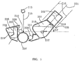
- waste guiding mechanisms 123, 124 can be set in the toner hopper 103, for guiding waste toners in the toner hopper 103 into the waste storage bin 104.
- the waste guiding mechanism is configured higher than an edge of the wiper blade 109, so that the waste toners can be guided to a position higher than the edge of the wiper blade 109, therefore, the waste toners are guided conveniently.
- the connection port between the waste storage bin 104 and the waste hopper 103 is higher than the edge of the wiper blade.
- FIG. 3 and FIG. 4 illustrate structure diagrams for the waste guiding mechanisms.
- the reference sign 123 means a belt type guide mechanism which comprises two delivery wheels and a belt surrounding the delivery wheels.
- the delivery wheels can be driven to rotate by manually rotating a rotary knob provided on the outer surface of the cartridge 100, so as to guide waste toners into the waste storage bin 104.
- the reference sign 124 means a blade type guide mechanism which comprises at least one blade.
- the end(s) of the blade(s) is/are bent near the photoconductor (OPC) drum, so that the blade(s) is/are formed as a L-shaped structure .
- This blade(s) can be pulled from outside, and the bending at the end(s) can be utilized to guide the waste toners into the waste storage bin 104.
- the above-mentioned photoconductor (OPC) drum 107 is configured as the above waste guiding mechanism. At this time, users can manually rotate the cartridge 100 upward by 90 degrees. A thrust generated by the rotation of photoconductor (OPC) drum can pass above the blade and automatically guide waste toners in the toner hopper into the stated waste storage bin.
- the continuous toner supplying cartridge 100 comprises at least two waste storage bins 104, and a one-way isolation mechanism, which can be one-way opened, is provided between the at least two waste storage bins 104.
- the isolation mechanism is configured such as a one-way valve, a plastic sheet or a metal sheet, to prevent a reverse flow of wastes.
- continuous toner supplying cartridge 100 with at least two toner storage bins 102 when toners in the toner hopper 101 are used up or nearly used up, users can open the first isolation mechanism 105, to automatically guide toners in the first toner storage bin into the toner hopper 101 under a gravity action. Hence toners can be automatically refilled and continuously supplied. Moreover, when toners in the first toner storage bin are used up or nearly used up, users can open the third isolation mechanism between the toner storage bins, so as to automatically guide toners in the second toner storage bin into the toner hopper 101 (by passing the first toner storage bin) under a gravity action. Hence toners are automatically refilled for the second time. The rest can be done in the same manner. In the continuous toner supplying cartridge 100 with more toner storage bins 102, continuous supply of toners can be realized in the same mode.
- a one-way isolation mechanism such as a one-way valve, a plastic sheet or a metal sheet so as to prevent wastes from reversely flowing.
- the cartridge is rotated upward by 90 degrees. Therefore, the wastes can be further guided into an empty waste storage bin, so as to clean up the waste hopper 103, and to fulfill the requirement of toner recycling under a printing task of continuously supplying toners. Therefore, when toners are automatically refilled from the toner storage bin into the toner hopper, it is not necessary to dump out waste toners.
- the waste hopper can be cleaned up by directly flipping or simply manually rotating. It is easy to operate. Moreover, the wastes will not be spilled, the environment would not be influenced, and human body would not be damaged.
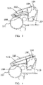
- FIG. 5 is a structure diagram for another embodiment about the continuous toner supplying cartridge according to present invention.
- the continuous toner supplying cartridge in this embodiment has a two-wing-shaped structure.
- this two-wing-shaped continuous toner supplying cartridge 200 comprises a toner hopper 201, a toner storage bin 202, a waste hopper 203 and a waste storage bin 204.
- a first isolation mechanism 205 is provided between the toner storage bin 202 and the toner hopper 201;
- a second isolation mechanism 206 is provided between the waste storage bin 204 and the waste hopper 203.
- the two-wing-shaped continuous toner supplying cartridge 200 further comprises a photoconductor (OPC) drum 207, a magnetic roller 208, a wiper blade 209, a primary charging roller (PCR) 210, a doctor blade 211, and a toner mixer 212.
- OPC photoconductor
- PCR primary charging roller
- doctor blade 211 a doctor blade 211
- toner mixer 212 a toner mixer
- the toner hopper 201, the toner storage bin 202, the waste hopper 203 and the waste storage bin 204 are all surrounding the photoconductor (OPC) drum 207.
- an approximate position of printer laser source 213 corresponding to the two-wing-shaped continuous toner supplying cartridge 200 is also marked out.
- the laser source 213 of the two-wing cartridge is vertically exposed downwards through a part between an upper wing and a lower wing the two-wing cartridge.
- the continuous toner supplying cartridge 200 is configured as a two-wing-shaped structure, and a connection port between the toner storage bin 202 and the toner hopper 201 is located in such a position that:
- the continuous toner supplying cartridge 200 is configured as a two-wing-shaped structure, and an available space for the toner storage bin 202 is located in such a position that:
- the reference sign 215 means the printer laser beam
- the reference sign 216 represents a pair of translation lines at an interval of 90 cm, which is the width of the toner storage bins 202.
- the reference sign 220 means the aforementioned perpendicular line
- the reference sign 221 represents the aforementioned upward line with the included angle of 45 degrees .
- the reference sign 217 means an inclination angle of toner storage bin 202, and the aforementioned perpendicular line 220 is set as the reference line.
- the value of the inclination angle of the toner storage bins 202 is in a certain range between 0 degree and 85 degrees, i.e. [0°, 85°].
- a reference sign 218 denotes toners
- a reference sign 219 denotes waste toners (wastes).
- the configurations described in the embodiments of FIG 1 and FIG. 2 can be adopted by the first isolation mechanisms 205 and the second isolation mechanism 206 in the present embodiment.
- a waste guiding mechanism can also be provided in this two-wing-shaped continuous toner supplying cartridge 200; and similarly the configurations described in the embodiments of FIG. 1 and FIG. 2 can be adopted for the waste guiding mechanism in the same manner.
- this two-wing-shaped continuous toner supplying cartridge 200 can also comprise at least two toner storage bins 202 and at least one waste storage bin 204, or adopt a design with at least one toner hopper 201 and at least two waste storage bins 204, so as to expand the toner capacity and the waste capacity of the whole two-wing-shaped continuous toner supplying cartridge 200.
- this invention proposes an image forming device (image forming device adopting electrophotography such as a printer, a copying machine). It possesses the continuous toner supplying cartridge in any of the above-mentioned embodiments.
- the continuous toner supplying cartridge proposed by the embodiments is adapted to the image forming device such as a printer, a copying machine, it is not necessary to modify the internal structure and boundary dimension of the image forming device such as a printer, a copying machine.
- An existing installation mode of the image forming device can be directly adopted.
- the continuous toner supplying cartridge proposed by this invention has the following significant advantages when compared with the prior art:
Landscapes
- Physics & Mathematics (AREA)
- General Physics & Mathematics (AREA)
- Engineering & Computer Science (AREA)
- Life Sciences & Earth Sciences (AREA)
- Environmental & Geological Engineering (AREA)
- Sustainable Development (AREA)
- Computer Vision & Pattern Recognition (AREA)
- Dry Development In Electrophotography (AREA)
- Cleaning In Electrography (AREA)
Applications Claiming Priority (2)
| Application Number | Priority Date | Filing Date | Title |
|---|---|---|---|
| CN201420567711 | 2014-09-29 | ||
| PCT/CN2015/000620 WO2016050001A1 (fr) | 2014-09-29 | 2015-08-31 | Tambour en sélénium susceptible de fournir une alimentation continue de poudre et dispositif de formation d'image |
Publications (2)
| Publication Number | Publication Date |
|---|---|
| EP3203324A1 true EP3203324A1 (fr) | 2017-08-09 |
| EP3203324A4 EP3203324A4 (fr) | 2018-05-02 |
Family
ID=52270303
Family Applications (1)
| Application Number | Title | Priority Date | Filing Date |
|---|---|---|---|
| EP15847730.7A Withdrawn EP3203324A4 (fr) | 2014-09-29 | 2015-08-31 | Tambour en sélénium susceptible de fournir une alimentation continue de poudre et dispositif de formation d'image |
Country Status (5)
| Country | Link |
|---|---|
| US (1) | US20170299980A1 (fr) |
| EP (1) | EP3203324A4 (fr) |
| CN (2) | CN204101890U (fr) |
| TW (1) | TWM517349U (fr) |
| WO (1) | WO2016050001A1 (fr) |
Cited By (2)
| Publication number | Priority date | Publication date | Assignee | Title |
|---|---|---|---|---|
| CN108163614A (zh) * | 2017-12-25 | 2018-06-15 | 珠海德键计算机外部设备有限公司 | 一种硒鼓密封件自动装贴线 |
| CN109917624A (zh) * | 2019-04-08 | 2019-06-21 | 钟隆君 | 便于再生及防止碳粉漂浮的磁式打印机用的再生碳粉盒 |
Families Citing this family (17)
| Publication number | Priority date | Publication date | Assignee | Title |
|---|---|---|---|---|
| CN204101890U (zh) * | 2014-09-29 | 2015-01-14 | 韩进龙 | 连续供粉硒鼓及图像形成装置 |
| CN106980254A (zh) * | 2016-01-18 | 2017-07-25 | 马鞍山澄果电子科技有限公司 | 硒鼓及具有硒鼓的图像形成装置 |
| CN107807507A (zh) * | 2017-10-24 | 2018-03-16 | 贵州云侠科技有限公司 | 便于清理的激光硒鼓 |
| CN109521662B (zh) * | 2018-12-04 | 2022-05-06 | 珠海奔图电子有限公司 | 双色图像生成方法、装置、设备及存储介质 |
| CN109634084B (zh) * | 2019-02-26 | 2024-03-26 | 天津光电通信技术有限公司 | 一种简易式激光打印机废粉清理的新型废粉仓 |
| CN112147864B (zh) * | 2019-06-28 | 2025-03-04 | 纳思达股份有限公司 | 显影盒 |
| CN112213931B (zh) * | 2019-07-12 | 2025-03-18 | 纳思达股份有限公司 | 一种显影盒 |
| CN112241118B (zh) * | 2019-07-16 | 2025-01-14 | 纳思达股份有限公司 | 一种显影盒 |
| CN110286573A (zh) * | 2019-07-30 | 2019-09-27 | 马鞍山澄果电子科技有限公司 | 一种碳粉盒及图像形成装置 |
| CN110515289A (zh) * | 2019-08-30 | 2019-11-29 | 珠海天威飞马打印耗材有限公司 | 处理盒及其改装方法 |
| CN111495908B (zh) * | 2020-05-28 | 2023-06-23 | 东莞市合鼎盛自动化设备有限公司 | 一种显像器自动清扫设备 |
| CN111665698B (zh) * | 2020-07-06 | 2024-06-14 | 浙江安普科技股份有限公司 | 一种端盖拆卸方便的硒鼓 |
| CN112684689A (zh) * | 2021-01-08 | 2021-04-20 | 中山市增盛塑料五金有限公司 | 一种免排废粉式处理盒 |
| CN113281975B (zh) * | 2021-04-28 | 2025-08-22 | 宁波得力科贝技术有限公司 | 一种粉仓、硒鼓以及打印机 |
| CN113156786A (zh) * | 2021-04-28 | 2021-07-23 | 宁波得力科贝技术有限公司 | 粉仓、硒鼓以及打印机 |
| CN113608422A (zh) * | 2021-07-21 | 2021-11-05 | 珠海天威飞马打印耗材有限公司 | 粉盒 |
| CN116430701B (zh) * | 2023-04-10 | 2026-01-06 | 北京莱盛高新技术有限公司 | 一种废粉仓、废粉传送轴及硒鼓 |
Family Cites Families (13)
| Publication number | Priority date | Publication date | Assignee | Title |
|---|---|---|---|---|
| JPS63101969U (fr) * | 1986-12-22 | 1988-07-02 | ||
| CA2105255C (fr) * | 1992-08-31 | 1999-08-03 | Yoshiaki Okano | Appareil electrophotographique empechant que le toner n'adhere a un element de contact du dispositif de transfert |
| JPH11174816A (ja) * | 1997-12-12 | 1999-07-02 | Canon Inc | 現像装置、プロセスカートリッジおよび画像形成装置 |
| JPH11327394A (ja) * | 1998-05-08 | 1999-11-26 | Ricoh Co Ltd | 画像形成装置 |
| JP2000305431A (ja) * | 1999-04-23 | 2000-11-02 | Copyer Co Ltd | クリーニング装置 |
| KR100532123B1 (ko) * | 2004-02-21 | 2005-11-29 | 삼성전자주식회사 | 현상장치 및 이를 구비한 전자사진방식 화상형성장치 |
| JP4715263B2 (ja) * | 2005-03-25 | 2011-07-06 | 富士ゼロックス株式会社 | クリーニング装置及びこれを用いたプロセスカートリッジ並びに画像形成装置 |
| KR100705384B1 (ko) * | 2005-08-16 | 2007-04-10 | 삼성전자주식회사 | 화상형성장치의 프로세스 카트리지 |
| JP2011133510A (ja) * | 2009-12-22 | 2011-07-07 | Canon Inc | 画像形成装置 |
| CN202548534U (zh) * | 2012-04-02 | 2012-11-21 | 珠海天威飞马打印耗材有限公司 | 粉盒 |
| CN202837818U (zh) * | 2012-09-17 | 2013-03-27 | 艾塔斯科技(镇江)有限公司 | 一种手动填充式墨粉匣 |
| CN103616808A (zh) * | 2013-10-17 | 2014-03-05 | 艾塔斯科技(镇江)有限公司 | 一种打印机墨粉容量扩充装置及其使用方法 |
| CN204101890U (zh) * | 2014-09-29 | 2015-01-14 | 韩进龙 | 连续供粉硒鼓及图像形成装置 |
-
2014
- 2014-10-10 CN CN201420583718.3U patent/CN204101890U/zh not_active Expired - Lifetime
- 2014-10-10 CN CN201410530999.0A patent/CN104317176A/zh active Pending
-
2015
- 2015-08-27 TW TW104213946U patent/TWM517349U/zh not_active IP Right Cessation
- 2015-08-31 US US15/513,234 patent/US20170299980A1/en not_active Abandoned
- 2015-08-31 WO PCT/CN2015/000620 patent/WO2016050001A1/fr not_active Ceased
- 2015-08-31 EP EP15847730.7A patent/EP3203324A4/fr not_active Withdrawn
Cited By (2)
| Publication number | Priority date | Publication date | Assignee | Title |
|---|---|---|---|---|
| CN108163614A (zh) * | 2017-12-25 | 2018-06-15 | 珠海德键计算机外部设备有限公司 | 一种硒鼓密封件自动装贴线 |
| CN109917624A (zh) * | 2019-04-08 | 2019-06-21 | 钟隆君 | 便于再生及防止碳粉漂浮的磁式打印机用的再生碳粉盒 |
Also Published As
| Publication number | Publication date |
|---|---|
| US20170299980A1 (en) | 2017-10-19 |
| TWM517349U (zh) | 2016-02-11 |
| WO2016050001A1 (fr) | 2016-04-07 |
| EP3203324A4 (fr) | 2018-05-02 |
| CN104317176A (zh) | 2015-01-28 |
| CN204101890U (zh) | 2015-01-14 |
Similar Documents
| Publication | Publication Date | Title |
|---|---|---|
| EP3203324A1 (fr) | Tambour en sélénium susceptible de fournir une alimentation continue de poudre et dispositif de formation d'image | |
| JP7581460B2 (ja) | 画像形成装置 | |
| JP4511583B2 (ja) | トナー補給装置、画像形成装置およびカラー画像形成装置 | |
| CN106980254A (zh) | 硒鼓及具有硒鼓的图像形成装置 | |
| US20110318062A1 (en) | Developer Conveying Device and Development Device, Toner Cartridge, and Cleaning Unit that are Provided with Developer Conveying Device | |
| CN106292221B (zh) | 粉体收容容器及图像形成装置 | |
| JP7475835B2 (ja) | カートリッジ及び画像形成装置 | |
| BR112013013698B1 (pt) | recipiente de pó, dispositivo de alimentação de pó e aparelho de formação de imagem | |
| JP4842357B2 (ja) | トナーカートリッジおよびこれを用いる画像形成装置 | |
| JP4423140B2 (ja) | トナー容器及びトナー補給装置並びに画像形成装置 | |
| KR101457759B1 (ko) | 현상제 수용 용기 및 이것이 장착된 화상 형성 장치 | |
| JP4842356B2 (ja) | トナーカートリッジおよびこれを用いる画像形成装置 | |
| CN102467061B (zh) | 用于显影剂的收容容器和图像形成装置 | |
| CN205594313U (zh) | 硒鼓及具有硒鼓的图像形成装置 | |
| JP6402542B2 (ja) | 画像形成装置 | |
| JP5540142B2 (ja) | 現像剤収容容器及びこれが適用された画像形成装置 | |
| CN103257549B (zh) | 粉末容器和图像形成装置 | |
| JP2010160205A (ja) | トナーカートリッジ及びこれを用いる画像形成装置 | |
| JP2012098673A (ja) | 廃トナー回収容器及び画像形成装置 | |
| US20130051882A1 (en) | Waste toner collecting container and process unit | |
| JP7711153B2 (ja) | 画像形成装置 | |
| CN102467064B (zh) | 显影剂储存容器和图像形成装置 | |
| JP2012002879A (ja) | 画像形成装置 | |
| JP6855019B2 (ja) | 粉体収納容器、プロセスカートリッジ、及び、画像形成装置 | |
| JP2016177261A (ja) | 画像形成装置 |
Legal Events
| Date | Code | Title | Description |
|---|---|---|---|
| PUAI | Public reference made under article 153(3) epc to a published international application that has entered the european phase |
Free format text: ORIGINAL CODE: 0009012 |
|
| 17P | Request for examination filed |
Effective date: 20170327 |
|
| AK | Designated contracting states |
Kind code of ref document: A1 Designated state(s): AL AT BE BG CH CY CZ DE DK EE ES FI FR GB GR HR HU IE IS IT LI LT LU LV MC MK MT NL NO PL PT RO RS SE SI SK SM TR |
|
| AX | Request for extension of the european patent |
Extension state: BA ME |
|
| RAP1 | Party data changed (applicant data changed or rights of an application transferred) |
Owner name: MAANSHAN CHENG GUO TECHNOLOGY CO., LTD Owner name: BEIJING LASER HI-TECHNOLOGY CO., LTD Owner name: HAN, CHIN-LUNG |
|
| RIN1 | Information on inventor provided before grant (corrected) |
Inventor name: BEIJING LASER HI-TECHNOLOGY CO., LTD Inventor name: MAANSHAN CHENG GUO TECHNOLOGY CO., LTD Inventor name: HAN, CHIN-LUNG |
|
| DAV | Request for validation of the european patent (deleted) | ||
| DAX | Request for extension of the european patent (deleted) | ||
| A4 | Supplementary search report drawn up and despatched |
Effective date: 20180403 |
|
| RIC1 | Information provided on ipc code assigned before grant |
Ipc: G03G 21/18 20060101ALI20180326BHEP Ipc: G03G 15/08 20060101AFI20180326BHEP Ipc: G03G 21/10 20060101ALN20180326BHEP Ipc: G03G 15/00 20060101ALI20180326BHEP Ipc: G03G 21/12 20060101ALI20180326BHEP |
|
| STAA | Information on the status of an ep patent application or granted ep patent |
Free format text: STATUS: THE APPLICATION IS DEEMED TO BE WITHDRAWN |
|
| 18D | Application deemed to be withdrawn |
Effective date: 20181031 |