EP3203543B1 - Élément électroluminescent - Google Patents
Élément électroluminescent Download PDFInfo
- Publication number
- EP3203543B1 EP3203543B1 EP15846617.7A EP15846617A EP3203543B1 EP 3203543 B1 EP3203543 B1 EP 3203543B1 EP 15846617 A EP15846617 A EP 15846617A EP 3203543 B1 EP3203543 B1 EP 3203543B1
- Authority
- EP
- European Patent Office
- Prior art keywords
- group
- compound
- film
- thickness
- layer
- Prior art date
- Legal status (The legal status is an assumption and is not a legal conclusion. Google has not performed a legal analysis and makes no representation as to the accuracy of the status listed.)
- Active
Links
- 0 C*(*=C)c1c(C)cc(*)c(*2OC*CC(C)(*)*2)c1 Chemical compound C*(*=C)c1c(C)cc(*)c(*2OC*CC(C)(*)*2)c1 0.000 description 8
- QQSBIXMLEGCZGD-UHFFFAOYSA-N C(C1)C=Cc2c1c1ccccc1[n]2-c1cccc(-[n]2c3ccccc3c3c2cccc3)c1 Chemical compound C(C1)C=Cc2c1c1ccccc1[n]2-c1cccc(-[n]2c3ccccc3c3c2cccc3)c1 QQSBIXMLEGCZGD-UHFFFAOYSA-N 0.000 description 1
- QYUZHSRSURQOLF-UHFFFAOYSA-N CCc(c1ccccc11)c(C)[n]1-c(cc1)cc2c1[s]c(cc1)c2cc1-[n]1c(cccc2)c2c2c1cccc2 Chemical compound CCc(c1ccccc11)c(C)[n]1-c(cc1)cc2c1[s]c(cc1)c2cc1-[n]1c(cccc2)c2c2c1cccc2 QYUZHSRSURQOLF-UHFFFAOYSA-N 0.000 description 1
- QUDBIPYGJFTXSV-UHFFFAOYSA-N Cc1cc(N(C2C=CC=CC22)c3c2cccc3)ccc1-c(c(C)c1)ccc1-[n]1c(cccc2)c2c2c1cccc2 Chemical compound Cc1cc(N(C2C=CC=CC22)c3c2cccc3)ccc1-c(c(C)c1)ccc1-[n]1c(cccc2)c2c2c1cccc2 QUDBIPYGJFTXSV-UHFFFAOYSA-N 0.000 description 1
- AFDMODCXODAXLC-UHFFFAOYSA-N N=Cc1ccccc1 Chemical compound N=Cc1ccccc1 AFDMODCXODAXLC-UHFFFAOYSA-N 0.000 description 1
- VFUDMQLBKNMONU-UHFFFAOYSA-N c(cc1)cc(c2ccccc22)c1[n]2-c(cc1)ccc1-c(cc1)ccc1-[n]1c2ccccc2c2c1cccc2 Chemical compound c(cc1)cc(c2ccccc22)c1[n]2-c(cc1)ccc1-c(cc1)ccc1-[n]1c2ccccc2c2c1cccc2 VFUDMQLBKNMONU-UHFFFAOYSA-N 0.000 description 1
Classifications
-
- C—CHEMISTRY; METALLURGY
- C09—DYES; PAINTS; POLISHES; NATURAL RESINS; ADHESIVES; COMPOSITIONS NOT OTHERWISE PROVIDED FOR; APPLICATIONS OF MATERIALS NOT OTHERWISE PROVIDED FOR
- C09K—MATERIALS FOR MISCELLANEOUS APPLICATIONS, NOT PROVIDED FOR ELSEWHERE
- C09K11/00—Luminescent materials, e.g. electroluminescent or chemiluminescent
- C09K11/02—Use of particular materials as binders, particle coatings or suspension media therefor
- C09K11/025—Use of particular materials as binders, particle coatings or suspension media therefor non-luminescent particle coatings or suspension media
-
- H—ELECTRICITY
- H10—SEMICONDUCTOR DEVICES; ELECTRIC SOLID-STATE DEVICES NOT OTHERWISE PROVIDED FOR
- H10K—ORGANIC ELECTRIC SOLID-STATE DEVICES
- H10K85/00—Organic materials used in the body or electrodes of devices covered by this subclass
- H10K85/30—Coordination compounds
- H10K85/341—Transition metal complexes, e.g. Ru(II)polypyridine complexes
-
- C—CHEMISTRY; METALLURGY
- C08—ORGANIC MACROMOLECULAR COMPOUNDS; THEIR PREPARATION OR CHEMICAL WORKING-UP; COMPOSITIONS BASED THEREON
- C08G—MACROMOLECULAR COMPOUNDS OBTAINED OTHERWISE THAN BY REACTIONS ONLY INVOLVING UNSATURATED CARBON-TO-CARBON BONDS
- C08G61/00—Macromolecular compounds obtained by reactions forming a carbon-to-carbon link in the main chain of the macromolecule
- C08G61/12—Macromolecular compounds containing atoms other than carbon in the main chain of the macromolecule
-
- C—CHEMISTRY; METALLURGY
- C09—DYES; PAINTS; POLISHES; NATURAL RESINS; ADHESIVES; COMPOSITIONS NOT OTHERWISE PROVIDED FOR; APPLICATIONS OF MATERIALS NOT OTHERWISE PROVIDED FOR
- C09K—MATERIALS FOR MISCELLANEOUS APPLICATIONS, NOT PROVIDED FOR ELSEWHERE
- C09K11/00—Luminescent materials, e.g. electroluminescent or chemiluminescent
- C09K11/06—Luminescent materials, e.g. electroluminescent or chemiluminescent containing organic luminescent materials
-
- H—ELECTRICITY
- H10—SEMICONDUCTOR DEVICES; ELECTRIC SOLID-STATE DEVICES NOT OTHERWISE PROVIDED FOR
- H10K—ORGANIC ELECTRIC SOLID-STATE DEVICES
- H10K50/00—Organic light-emitting devices
-
- H—ELECTRICITY
- H10—SEMICONDUCTOR DEVICES; ELECTRIC SOLID-STATE DEVICES NOT OTHERWISE PROVIDED FOR
- H10K—ORGANIC ELECTRIC SOLID-STATE DEVICES
- H10K50/00—Organic light-emitting devices
- H10K50/10—OLEDs or polymer light-emitting diodes [PLED]
- H10K50/11—OLEDs or polymer light-emitting diodes [PLED] characterised by the electroluminescent [EL] layers
-
- H—ELECTRICITY
- H10—SEMICONDUCTOR DEVICES; ELECTRIC SOLID-STATE DEVICES NOT OTHERWISE PROVIDED FOR
- H10K—ORGANIC ELECTRIC SOLID-STATE DEVICES
- H10K85/00—Organic materials used in the body or electrodes of devices covered by this subclass
- H10K85/10—Organic polymers or oligomers
- H10K85/111—Organic polymers or oligomers comprising aromatic, heteroaromatic, or aryl chains, e.g. polyaniline, polyphenylene or polyphenylene vinylene
- H10K85/115—Polyfluorene; Derivatives thereof
-
- H—ELECTRICITY
- H10—SEMICONDUCTOR DEVICES; ELECTRIC SOLID-STATE DEVICES NOT OTHERWISE PROVIDED FOR
- H10K—ORGANIC ELECTRIC SOLID-STATE DEVICES
- H10K85/00—Organic materials used in the body or electrodes of devices covered by this subclass
- H10K85/10—Organic polymers or oligomers
- H10K85/151—Copolymers
-
- H—ELECTRICITY
- H10—SEMICONDUCTOR DEVICES; ELECTRIC SOLID-STATE DEVICES NOT OTHERWISE PROVIDED FOR
- H10K—ORGANIC ELECTRIC SOLID-STATE DEVICES
- H10K85/00—Organic materials used in the body or electrodes of devices covered by this subclass
- H10K85/30—Coordination compounds
- H10K85/341—Transition metal complexes, e.g. Ru(II)polypyridine complexes
- H10K85/342—Transition metal complexes, e.g. Ru(II)polypyridine complexes comprising iridium
-
- H—ELECTRICITY
- H10—SEMICONDUCTOR DEVICES; ELECTRIC SOLID-STATE DEVICES NOT OTHERWISE PROVIDED FOR
- H10K—ORGANIC ELECTRIC SOLID-STATE DEVICES
- H10K85/00—Organic materials used in the body or electrodes of devices covered by this subclass
- H10K85/30—Coordination compounds
- H10K85/341—Transition metal complexes, e.g. Ru(II)polypyridine complexes
- H10K85/346—Transition metal complexes, e.g. Ru(II)polypyridine complexes comprising platinum
-
- C—CHEMISTRY; METALLURGY
- C08—ORGANIC MACROMOLECULAR COMPOUNDS; THEIR PREPARATION OR CHEMICAL WORKING-UP; COMPOSITIONS BASED THEREON
- C08G—MACROMOLECULAR COMPOUNDS OBTAINED OTHERWISE THAN BY REACTIONS ONLY INVOLVING UNSATURATED CARBON-TO-CARBON BONDS
- C08G2261/00—Macromolecular compounds obtained by reactions forming a carbon-to-carbon link in the main chain of the macromolecule
- C08G2261/10—Definition of the polymer structure
- C08G2261/12—Copolymers
- C08G2261/124—Copolymers alternating
-
- C—CHEMISTRY; METALLURGY
- C08—ORGANIC MACROMOLECULAR COMPOUNDS; THEIR PREPARATION OR CHEMICAL WORKING-UP; COMPOSITIONS BASED THEREON
- C08G—MACROMOLECULAR COMPOUNDS OBTAINED OTHERWISE THAN BY REACTIONS ONLY INVOLVING UNSATURATED CARBON-TO-CARBON BONDS
- C08G2261/00—Macromolecular compounds obtained by reactions forming a carbon-to-carbon link in the main chain of the macromolecule
- C08G2261/10—Definition of the polymer structure
- C08G2261/14—Side-groups
- C08G2261/141—Side-chains having aliphatic units
- C08G2261/1412—Saturated aliphatic units
-
- C—CHEMISTRY; METALLURGY
- C08—ORGANIC MACROMOLECULAR COMPOUNDS; THEIR PREPARATION OR CHEMICAL WORKING-UP; COMPOSITIONS BASED THEREON
- C08G—MACROMOLECULAR COMPOUNDS OBTAINED OTHERWISE THAN BY REACTIONS ONLY INVOLVING UNSATURATED CARBON-TO-CARBON BONDS
- C08G2261/00—Macromolecular compounds obtained by reactions forming a carbon-to-carbon link in the main chain of the macromolecule
- C08G2261/10—Definition of the polymer structure
- C08G2261/14—Side-groups
- C08G2261/141—Side-chains having aliphatic units
- C08G2261/1414—Unsaturated aliphatic units
-
- C—CHEMISTRY; METALLURGY
- C08—ORGANIC MACROMOLECULAR COMPOUNDS; THEIR PREPARATION OR CHEMICAL WORKING-UP; COMPOSITIONS BASED THEREON
- C08G—MACROMOLECULAR COMPOUNDS OBTAINED OTHERWISE THAN BY REACTIONS ONLY INVOLVING UNSATURATED CARBON-TO-CARBON BONDS
- C08G2261/00—Macromolecular compounds obtained by reactions forming a carbon-to-carbon link in the main chain of the macromolecule
- C08G2261/10—Definition of the polymer structure
- C08G2261/14—Side-groups
- C08G2261/142—Side-chains containing oxygen
- C08G2261/1424—Side-chains containing oxygen containing ether groups, including alkoxy
-
- C—CHEMISTRY; METALLURGY
- C08—ORGANIC MACROMOLECULAR COMPOUNDS; THEIR PREPARATION OR CHEMICAL WORKING-UP; COMPOSITIONS BASED THEREON
- C08G—MACROMOLECULAR COMPOUNDS OBTAINED OTHERWISE THAN BY REACTIONS ONLY INVOLVING UNSATURATED CARBON-TO-CARBON BONDS
- C08G2261/00—Macromolecular compounds obtained by reactions forming a carbon-to-carbon link in the main chain of the macromolecule
- C08G2261/10—Definition of the polymer structure
- C08G2261/14—Side-groups
- C08G2261/142—Side-chains containing oxygen
- C08G2261/1426—Side-chains containing oxygen containing carboxy groups (COOH) and/or -C(=O)O-moieties
-
- C—CHEMISTRY; METALLURGY
- C08—ORGANIC MACROMOLECULAR COMPOUNDS; THEIR PREPARATION OR CHEMICAL WORKING-UP; COMPOSITIONS BASED THEREON
- C08G—MACROMOLECULAR COMPOUNDS OBTAINED OTHERWISE THAN BY REACTIONS ONLY INVOLVING UNSATURATED CARBON-TO-CARBON BONDS
- C08G2261/00—Macromolecular compounds obtained by reactions forming a carbon-to-carbon link in the main chain of the macromolecule
- C08G2261/10—Definition of the polymer structure
- C08G2261/14—Side-groups
- C08G2261/148—Side-chains having aromatic units
-
- C—CHEMISTRY; METALLURGY
- C08—ORGANIC MACROMOLECULAR COMPOUNDS; THEIR PREPARATION OR CHEMICAL WORKING-UP; COMPOSITIONS BASED THEREON
- C08G—MACROMOLECULAR COMPOUNDS OBTAINED OTHERWISE THAN BY REACTIONS ONLY INVOLVING UNSATURATED CARBON-TO-CARBON BONDS
- C08G2261/00—Macromolecular compounds obtained by reactions forming a carbon-to-carbon link in the main chain of the macromolecule
- C08G2261/10—Definition of the polymer structure
- C08G2261/18—Definition of the polymer structure conjugated
-
- C—CHEMISTRY; METALLURGY
- C08—ORGANIC MACROMOLECULAR COMPOUNDS; THEIR PREPARATION OR CHEMICAL WORKING-UP; COMPOSITIONS BASED THEREON
- C08G—MACROMOLECULAR COMPOUNDS OBTAINED OTHERWISE THAN BY REACTIONS ONLY INVOLVING UNSATURATED CARBON-TO-CARBON BONDS
- C08G2261/00—Macromolecular compounds obtained by reactions forming a carbon-to-carbon link in the main chain of the macromolecule
- C08G2261/10—Definition of the polymer structure
- C08G2261/22—Molecular weight
- C08G2261/228—Polymers, i.e. more than 10 repeat units
-
- C—CHEMISTRY; METALLURGY
- C08—ORGANIC MACROMOLECULAR COMPOUNDS; THEIR PREPARATION OR CHEMICAL WORKING-UP; COMPOSITIONS BASED THEREON
- C08G—MACROMOLECULAR COMPOUNDS OBTAINED OTHERWISE THAN BY REACTIONS ONLY INVOLVING UNSATURATED CARBON-TO-CARBON BONDS
- C08G2261/00—Macromolecular compounds obtained by reactions forming a carbon-to-carbon link in the main chain of the macromolecule
- C08G2261/30—Monomer units or repeat units incorporating structural elements in the main chain
- C08G2261/31—Monomer units or repeat units incorporating structural elements in the main chain incorporating aromatic structural elements in the main chain
- C08G2261/312—Non-condensed aromatic systems, e.g. benzene
-
- C—CHEMISTRY; METALLURGY
- C08—ORGANIC MACROMOLECULAR COMPOUNDS; THEIR PREPARATION OR CHEMICAL WORKING-UP; COMPOSITIONS BASED THEREON
- C08G—MACROMOLECULAR COMPOUNDS OBTAINED OTHERWISE THAN BY REACTIONS ONLY INVOLVING UNSATURATED CARBON-TO-CARBON BONDS
- C08G2261/00—Macromolecular compounds obtained by reactions forming a carbon-to-carbon link in the main chain of the macromolecule
- C08G2261/30—Monomer units or repeat units incorporating structural elements in the main chain
- C08G2261/31—Monomer units or repeat units incorporating structural elements in the main chain incorporating aromatic structural elements in the main chain
- C08G2261/314—Condensed aromatic systems, e.g. perylene, anthracene or pyrene
- C08G2261/3142—Condensed aromatic systems, e.g. perylene, anthracene or pyrene fluorene-based, e.g. fluorene, indenofluorene, or spirobifluorene
-
- C—CHEMISTRY; METALLURGY
- C08—ORGANIC MACROMOLECULAR COMPOUNDS; THEIR PREPARATION OR CHEMICAL WORKING-UP; COMPOSITIONS BASED THEREON
- C08G—MACROMOLECULAR COMPOUNDS OBTAINED OTHERWISE THAN BY REACTIONS ONLY INVOLVING UNSATURATED CARBON-TO-CARBON BONDS
- C08G2261/00—Macromolecular compounds obtained by reactions forming a carbon-to-carbon link in the main chain of the macromolecule
- C08G2261/30—Monomer units or repeat units incorporating structural elements in the main chain
- C08G2261/31—Monomer units or repeat units incorporating structural elements in the main chain incorporating aromatic structural elements in the main chain
- C08G2261/316—Monomer units or repeat units incorporating structural elements in the main chain incorporating aromatic structural elements in the main chain bridged by heteroatoms, e.g. N, P, Si or B
- C08G2261/3162—Arylamines
-
- C—CHEMISTRY; METALLURGY
- C08—ORGANIC MACROMOLECULAR COMPOUNDS; THEIR PREPARATION OR CHEMICAL WORKING-UP; COMPOSITIONS BASED THEREON
- C08G—MACROMOLECULAR COMPOUNDS OBTAINED OTHERWISE THAN BY REACTIONS ONLY INVOLVING UNSATURATED CARBON-TO-CARBON BONDS
- C08G2261/00—Macromolecular compounds obtained by reactions forming a carbon-to-carbon link in the main chain of the macromolecule
- C08G2261/90—Applications
- C08G2261/95—Use in organic luminescent diodes
-
- C—CHEMISTRY; METALLURGY
- C09—DYES; PAINTS; POLISHES; NATURAL RESINS; ADHESIVES; COMPOSITIONS NOT OTHERWISE PROVIDED FOR; APPLICATIONS OF MATERIALS NOT OTHERWISE PROVIDED FOR
- C09K—MATERIALS FOR MISCELLANEOUS APPLICATIONS, NOT PROVIDED FOR ELSEWHERE
- C09K2211/00—Chemical nature of organic luminescent or tenebrescent compounds
- C09K2211/10—Non-macromolecular compounds
- C09K2211/1003—Carbocyclic compounds
- C09K2211/1007—Non-condensed systems
-
- C—CHEMISTRY; METALLURGY
- C09—DYES; PAINTS; POLISHES; NATURAL RESINS; ADHESIVES; COMPOSITIONS NOT OTHERWISE PROVIDED FOR; APPLICATIONS OF MATERIALS NOT OTHERWISE PROVIDED FOR
- C09K—MATERIALS FOR MISCELLANEOUS APPLICATIONS, NOT PROVIDED FOR ELSEWHERE
- C09K2211/00—Chemical nature of organic luminescent or tenebrescent compounds
- C09K2211/10—Non-macromolecular compounds
- C09K2211/1018—Heterocyclic compounds
- C09K2211/1025—Heterocyclic compounds characterised by ligands
- C09K2211/1029—Heterocyclic compounds characterised by ligands containing one nitrogen atom as the heteroatom
-
- C—CHEMISTRY; METALLURGY
- C09—DYES; PAINTS; POLISHES; NATURAL RESINS; ADHESIVES; COMPOSITIONS NOT OTHERWISE PROVIDED FOR; APPLICATIONS OF MATERIALS NOT OTHERWISE PROVIDED FOR
- C09K—MATERIALS FOR MISCELLANEOUS APPLICATIONS, NOT PROVIDED FOR ELSEWHERE
- C09K2211/00—Chemical nature of organic luminescent or tenebrescent compounds
- C09K2211/10—Non-macromolecular compounds
- C09K2211/1018—Heterocyclic compounds
- C09K2211/1025—Heterocyclic compounds characterised by ligands
- C09K2211/1044—Heterocyclic compounds characterised by ligands containing two nitrogen atoms as heteroatoms
-
- C—CHEMISTRY; METALLURGY
- C09—DYES; PAINTS; POLISHES; NATURAL RESINS; ADHESIVES; COMPOSITIONS NOT OTHERWISE PROVIDED FOR; APPLICATIONS OF MATERIALS NOT OTHERWISE PROVIDED FOR
- C09K—MATERIALS FOR MISCELLANEOUS APPLICATIONS, NOT PROVIDED FOR ELSEWHERE
- C09K2211/00—Chemical nature of organic luminescent or tenebrescent compounds
- C09K2211/10—Non-macromolecular compounds
- C09K2211/1018—Heterocyclic compounds
- C09K2211/1025—Heterocyclic compounds characterised by ligands
- C09K2211/1092—Heterocyclic compounds characterised by ligands containing sulfur as the only heteroatom
-
- C—CHEMISTRY; METALLURGY
- C09—DYES; PAINTS; POLISHES; NATURAL RESINS; ADHESIVES; COMPOSITIONS NOT OTHERWISE PROVIDED FOR; APPLICATIONS OF MATERIALS NOT OTHERWISE PROVIDED FOR
- C09K—MATERIALS FOR MISCELLANEOUS APPLICATIONS, NOT PROVIDED FOR ELSEWHERE
- C09K2211/00—Chemical nature of organic luminescent or tenebrescent compounds
- C09K2211/18—Metal complexes
- C09K2211/185—Metal complexes of the platinum group, i.e. Os, Ir, Pt, Ru, Rh or Pd
-
- H—ELECTRICITY
- H10—SEMICONDUCTOR DEVICES; ELECTRIC SOLID-STATE DEVICES NOT OTHERWISE PROVIDED FOR
- H10K—ORGANIC ELECTRIC SOLID-STATE DEVICES
- H10K2101/00—Properties of the organic materials covered by group H10K85/00
- H10K2101/10—Triplet emission
-
- H—ELECTRICITY
- H10—SEMICONDUCTOR DEVICES; ELECTRIC SOLID-STATE DEVICES NOT OTHERWISE PROVIDED FOR
- H10K—ORGANIC ELECTRIC SOLID-STATE DEVICES
- H10K50/00—Organic light-emitting devices
- H10K50/10—OLEDs or polymer light-emitting diodes [PLED]
- H10K50/14—Carrier transporting layers
- H10K50/15—Hole transporting layers
-
- H—ELECTRICITY
- H10—SEMICONDUCTOR DEVICES; ELECTRIC SOLID-STATE DEVICES NOT OTHERWISE PROVIDED FOR
- H10K—ORGANIC ELECTRIC SOLID-STATE DEVICES
- H10K50/00—Organic light-emitting devices
- H10K50/10—OLEDs or polymer light-emitting diodes [PLED]
- H10K50/14—Carrier transporting layers
- H10K50/16—Electron transporting layers
-
- H—ELECTRICITY
- H10—SEMICONDUCTOR DEVICES; ELECTRIC SOLID-STATE DEVICES NOT OTHERWISE PROVIDED FOR
- H10K—ORGANIC ELECTRIC SOLID-STATE DEVICES
- H10K50/00—Organic light-emitting devices
- H10K50/10—OLEDs or polymer light-emitting diodes [PLED]
- H10K50/17—Carrier injection layers
-
- H—ELECTRICITY
- H10—SEMICONDUCTOR DEVICES; ELECTRIC SOLID-STATE DEVICES NOT OTHERWISE PROVIDED FOR
- H10K—ORGANIC ELECTRIC SOLID-STATE DEVICES
- H10K50/00—Organic light-emitting devices
- H10K50/10—OLEDs or polymer light-emitting diodes [PLED]
- H10K50/17—Carrier injection layers
- H10K50/171—Electron injection layers
-
- H—ELECTRICITY
- H10—SEMICONDUCTOR DEVICES; ELECTRIC SOLID-STATE DEVICES NOT OTHERWISE PROVIDED FOR
- H10K—ORGANIC ELECTRIC SOLID-STATE DEVICES
- H10K85/00—Organic materials used in the body or electrodes of devices covered by this subclass
- H10K85/60—Organic compounds having low molecular weight
- H10K85/615—Polycyclic condensed aromatic hydrocarbons, e.g. anthracene
- H10K85/626—Polycyclic condensed aromatic hydrocarbons, e.g. anthracene containing more than one polycyclic condensed aromatic rings, e.g. bis-anthracene
Definitions
- the present invention relates to a light-emitting device.
- Light-emitting devices such as organic electroluminescence devices (organic EL devices), because having properties such as a high external quantum efficiency and a low-voltage drive, can suitably be used in applications of display and illumination, and have recently attracted attention.
- the light-emitting devices comprise organic layers such as a light emitting layer and a charge transporting layer.
- Patent Literatures 1 and 2 describe light-emitting devices comprising a light emitting layer formed by using a blue phosphorescent compound having a ligand formed from a 6-membered ring and a 5-membered ring, and a hole transporting layer formed by using a polymer compound comprising an aromatic amine constitutional unit and a crosslinkable constitutional unit.
- the blue phosphorescent compound described in Patent Literature 2 is a phosphorescent compound represented by the following formula.
- the polymer compound comprising an aromatic amine constitutional unit and a crosslinkable constitutional unit described in Patent Literature 2 is a polymer compound represented by the following formula.
- the value of (Y 1 ⁇ 1000)/X 1 described later of the polymer compound is calculated, and is 0.09.
- EP3131131 may be citable under Article 54(3) EPC.
- the document relates to a light emitting device comprising an anode, a cathode, a first organic layer disposed between the anode and the cathode and a second organic layer disposed between the anode and the cathode, wherein the first organic layer is a layer obtained by using a composition comprising a compound represented by the formula (H-A) and a metal complex represented by the formula (1), and the second organic layer is a layer obtained by using a polymer compound comprising a constitutional unit having a crosslinkable group: wherein Z A represents a group represented by -N(R ZA )-, a sulfur atom, an oxygen atom or the like, and R ZA and R Z1 to R Z4 represent a hydrogen atom or a substituent, and at least one of R Z1 to R Z4 is a monovalent heterocyclic group, Z 1 to Z 4 represent a carbon atom or a nitrogen atom, and the
- the document also discloses a method of preparing a light emitting device as follows:
- a polymer compound HTL-1 was dissolved at a concentration of 0.7 wt% in xylene, wherein HTL-1 is a copolymer constituted of constitutional units derived from the monomer compounds CM1, CM2, CM3 and CM4 at a molar ratio of 50:5:5:40; the resultant xylene solution was spin-coated on the hole injection layer to form a film with a thickness of 20 nm, and the film was heated on a hot plate at 180°C for 60 minutes under a nitrogen gas atmosphere, to form a hole transporting layer.
- the substrate carrying the light emitting layer formed thereon was placed in a vapor deposition machine, and the pressure was reduced to 1.0 x 10 -4 Pa or less, then, as a cathode, sodium fluoride was vapor-deposited with a thickness of about 7 nm on the light emitting layer, then, aluminum was vapor-deposited with a thickness of about 120 nm on the sodium fluoride layer; after vapor deposition, sealing was performed using a glass substrate, to fabricate a light emitting device.
- This subject-matter is disclaimed from the present claims.
- EP3154101 may be citable under Article 54(3) EPC.
- the document relates to a light emitting device comprising an anode, a cathode, a first organic layer disposed between the anode and the cathode (a layer comprising one or more phosphorescent compounds) and a second organic layer disposed between the anode and the first organic layer (a layer comprising one or more phosphorescent compounds and a crosslinked body of a crosslinkable material), wherein at least one phosphorescent compound contained in the first organic layer and at least one phosphorescent compound contained in the second organic layer are the same phosphorescent compound represented by the formula (1): wherein M represents an iridium atom or the like, n 1 represents an integer of 1 or more, n 2 represents an integer of 0 or more, E 1 and E 2 represent a carbon atom or the like, the ring L 1 represents an aromatic heterocyclic ring, the ring L 2 represents an aromatic hydrocarbon ring or the like, A 1 -G 1
- the document also discloses methods of preparing light emitting devices as follows: (b) A glass substrate was attached with an ITO film with a thickness of 45 nm by a sputtering method, to form an anode; on the anode, a polythiophene-sulfonic acid type hole injection agent AQ-1200 (manufactured by Plectronics) was spin-coated to form a film with a thickness of 35 nm, and the film was heated on a hot plate at 170°C for 15 minutes under an air atmosphere, thereby forming a hole injection layer.
- a polythiophene-sulfonic acid type hole injection agent AQ-1200 manufactured by Plectronics
- DCzDBT 2,8-di(9H-carbazol-9-yl)dibenzo[b,d]thiophene
- the polymer compound P4 was dissolved at a concentration of 0.25 wt% in 2,2,3,3,4,4,5,5-octafluoro-1-pentanol; the resultant 2,2,3,3,4,4,5,5-octafluoro-1-pentanol solution was spin-coated on the light emitting layer to form a film with a thickness of 10 nm, and the film was heated at 130°C for 10 minutes under a nitrogen gas atmosphere, thereby forming an electron transporting layer.
- the substrate carrying the electron transporting layer formed thereon was placed in a vapor deposition machine, and the pressured was reduced to 1.0 x 10 -4 Pa or less, then, as a cathode, sodium fluoride was vapor-deposited with a thickness of about 4 nm on the light emitting layer, then, aluminum was vapor-deposited with a thickness of about 80 nm on the sodium fluoride layer; after vapor deposition, sealing with a glass substrate was performed, thereby fabricating a light emitting device.
- a glass substrate was attached with an ITO film with a thickness of 45 nm by a sputtering method, to form an anode; on the anode, a polythiophene-sulfonic acid type hole injection agent AQ-1200 (manufactured by Plectronics) was spin-coated to form a film with a thickness of 35 nm, and the film was heated on a hot plate at 170°C for 15 minutes under an air atmosphere, thereby forming a hole injection layer.
- a polythiophene-sulfonic acid type hole injection agent AQ-1200 manufactured by Plectronics
- DCzDBT 2,8-di(9H-carbazol-9-yl)dibenzo[b,d]thiophene
- the polymer compound P4 as defined in (b) above was dissolved at a concentration of 0.25 wt% in 2,2,3,3,4,4,5,5-octafluoro-1-pentanol; the resultant 2,2,3,3,4,4,5,5-octafluoro-1-pentanol solution was spin-coated on the light emitting layer to form a film with a thickness of 10 nm, and the film was heated at 130°C for 10 minutes under a nitrogen gas atmosphere, thereby forming an electron transporting layer.
- the substrate carrying the electron transporting layer formed thereon was placed in a vapor deposition machine, and the pressured was reduced to 1.0 x 10 -4 Pa or less, then, as a cathode, sodium fluoride was vapor-deposited with a thickness of about 4 nm on the light emitting layer, then, aluminum was vapor-deposited with a thickness of about 80 nm on the sodium fluoride layer; after vapor deposition, sealing with a glass substrate was performed, thereby fabricating a light emitting device.
- a glass substrate was attached with an ITO film with a thickness of 45 nm by a sputtering method, to form an anode; on the anode, a polythiophene-sulfonic acid type hole injection agent AQ-1200 (manufactured by Plectronics) was spin-coated to form a film with a thickness of 35 nm, and the film was heated on a hot plate at 170°C for 15 minutes under an air atmosphere, thereby forming a hole injection layer.
- a polythiophene-sulfonic acid type hole injection agent AQ-1200 manufactured by Plectronics
- DCzDBT 2,8-di(9H-carbazol-9-yl)dibenzo[b,d]thiophene
- the polymer compound P4 as defined in (b) above was dissolved at a concentration of 0.25 wt% in 2,2,3,3,4,4,5,5-octafluoro-1-pentanol; the resultant 2,2,3,3,4,4,5,5-octafluoro-1-pentanol solution was spin-coated on the light emitting layer to form a film with a thickness of 10 nm, and the film was heated at 130°C for 10 minutes under a nitrogen gas atmosphere, thereby forming an electron transporting layer.
- the substrate carrying the electron transporting layer formed thereon was placed in a vapor deposition machine, and the pressured was reduced to 1.0 x 10 -4 Pa or less, then, as a cathode, sodium fluoride was vapor-deposited with a thickness of about 4 nm on the light emitting layer, then, aluminum was vapor-deposited with a thickness of about 80 nm on the sodium fluoride layer; after vapor deposition, sealing with a glass substrate was performed, thereby fabricating a light emitting device.
- a glass substrate was attached with an ITO film with a thickness of 45 nm by a sputtering method, to form an anode; on the anode, a polythiophene-sulfonic acid type hole injection agent AQ-1200 (manufactured by Plectronics) was spin-coated to form a film with a thickness of 35 nm, and the film was heated on a hot plate at 170°C for 15 minutes under an air atmosphere, thereby forming a hole injection layer.
- a polythiophene-sulfonic acid type hole injection agent AQ-1200 manufactured by Plectronics
- DCzDBT 2,8-di(9H-carbazol-9-yl)dibenzo[b,d]thiophene
- the polymer compound P4 as defined in (b) above was dissolved at a concentration of 0.25 wt% in 2,2,3,3,4,4,5,5-octafluoro-1-pentanol; the resultant 2,2,3,3,4,4,5,5-octafluoro-1-pentanol solution was spin-coated on the light emitting layer to form a film with a thickness of 10 nm, and the film was heated at 130°C for 10 minutes under a nitrogen gas atmosphere, thereby forming an electron transporting layer.
- the substrate carrying the electron transporting layer formed thereon was placed in a vapor deposition machine, and the pressured was reduced to 1.0 x 10 -4 Pa or less, then, as a cathode, sodium fluoride was vapor-deposited with a thickness of about 4 nm on the light emitting layer, then, aluminum was vapor-deposited with a thickness of about 80 nm on the sodium fluoride layer; after vapor deposition, sealing with a glass substrate was performed, thereby fabricating a light emitting device.
- a glass substrate was attached with an ITO film with a thickness of 45 nm by a sputtering method, to form an anode; on the anode, a polythiophene-sulfonic acid type hole injection agent AQ-1200 (manufactured by Plectronics) was spin-coated to form a film with a thickness of 35 nm, and the film was heated on a hot plate at 170°C for 15 minutes under an air atmosphere, thereby forming a hole injection layer.
- a polythiophene-sulfonic acid type hole injection agent AQ-1200 manufactured by Plectronics
- DCzDBT 2,8-di(9H-carbazol-9-yl)dibenzo[b,d]thiophene
- the polymer compound P4 as defined in (b) above was dissolved at a concentration of 0.25 wt% in 2,2,3,3,4,4,5,5-octafluoro-1-pentanol; the resultant 2,2,3,3,4,4,5,5-octafluoro-1-pentanol solution was spin-coated on the light emitting layer to form a film with a thickness of 10 nm, and the film was heated at 130°C for 10 minutes under a nitrogen gas atmosphere, thereby forming an electron transporting layer.
- the substrate carrying the electron transporting layer formed thereon was placed in a vapor deposition machine, and the pressured was reduced to 1.0 x 10 -4 Pa or less, then, as a cathode, sodium fluoride was vapor-deposited with a thickness of about 4 nm on the light emitting layer, then, aluminum was vapor-deposited with a thickness of about 80 nm on the sodium fluoride layer; after vapor deposition, sealing with a glass substrate was performed, thereby fabricating a light emitting device.
- a glass substrate was attached with an ITO film with a thickness of 45 nm by a sputtering method, to form an anode; on the anode, a polythiophene-sulfonic acid type hole injection agent AQ-1200 (manufactured by Plectronics) was spin-coated to form a film with a thickness of 35 nm, and the film was heated on a hot plate at 170°C for 15 minutes under an air atmosphere, thereby forming a hole injection layer.
- a polythiophene-sulfonic acid type hole injection agent AQ-1200 manufactured by Plectronics
- the polymer compound P1 as defined in (b) above was dissolved at a concentration of 0.5 wt% in chlorobenzene; the resultant chlorobenzene solution was spin-coated on the hole injection layer to form a film with a thickness of 20 nm, and the film was heated on a hot plate at 180°C for 60 minutes under a nitrogen gas atmosphere, thereby forming a hole transporting layer; by heating on a hot plate at 180°C for 60 minutes, the polymer compound P1 becomes a crosslinked body of the polymer compound P1.
- DCzDBT 2,8-di(9H-carbazol-9-yl)dibenzo[b,d]thiophene
- the polymer compound P4 as defined in (b) above was dissolved at a concentration of 0.25 wt% in 2,2,3,3,4,4,5,5-octafluoro-1-pentanol; the resultant 2,2,3,3,4,4,5,5-octafluoro-1-pentanol solution was spin-coated on the light emitting layer to form a film with a thickness of 10 nm, and the film was heated at 130°C for 10 minutes under a nitrogen gas atmosphere, thereby forming an electron transporting layer.
- the substrate carrying the electron transporting layer formed thereon was placed in a vapor deposition machine, and the pressured was reduced to 1.0 x 10 -4 Pa or less, then, as a cathode, sodium fluoride was vapor-deposited with a thickness of about 4 nm on the light emitting layer, then, aluminum was vapor-deposited with a thickness of about 80 nm on the sodium fluoride layer; after vapor deposition, sealing with a glass substrate was performed, thereby fabricating a light emitting device.
- a glass substrate was attached with an ITO film with a thickness of 45 nm by a sputtering method, to form an anode; on the anode, a polythiophene-sulfonic acid type hole injection agent AQ-1200 (manufactured by Plectronics) was spin-coated to form a film with a thickness of 35 nm, and the film was heated on a hot plate at 170°C for 15 minutes under an air atmosphere, thereby forming a hole injection layer.
- a polythiophene-sulfonic acid type hole injection agent AQ-1200 manufactured by Plectronics
- the polymer compound P1 as defined in (b) above was dissolved at a concentration of 0.5 wt% in chlorobenzene; the resultant chlorobenzene solution was spin-coated on the hole injection layer to form a film with a thickness of 20 nm, and the film was heated on a hot plate at 180°C for 60 minutes under a nitrogen gas atmosphere, thereby forming a hole transporting layer; by heating on a hot plate at 180°C for 60 minutes, the polymer compound P1 becomes a crosslinked body of the polymer compound P1.
- DCzDBT 2,8-di(9H-carbazol-9-yl)dibenzo[b,d]thiophene
- the polymer compound P4 as defined in (b) above was dissolved at a concentration of 0.25 wt% in 2,2,3,3,4,4,5,5-octafluoro-1-pentanol; the resultant 2,2,3,3,4,4,5,5-octafluoro-1-pentanol solution was spin-coated on the light emitting layer to form a film with a thickness of 10 nm, and the film was heated at 130°C for 10 minutes under a nitrogen gas atmosphere, thereby forming an electron transporting layer.
- the substrate carrying the electron transporting layer formed thereon was placed in a vapor deposition machine, and the pressured was reduced to 1.0 x 10 -4 Pa or less, then, as a cathode, sodium fluoride was vapor-deposited with a thickness of about 4 nm on the light emitting layer, then, aluminum was vapor-deposited with a thickness of about 80 nm on the sodium fluoride layer; after vapor deposition, sealing with a glass substrate was performed, thereby fabricating a light emitting device.
- This subject-matter is disclaimed from the present claims.
- EP3136462 may be citable under Article 54(3) EPC.
- the document relates to a light emitting device comprises an anode, a cathode, a first light-emitting layer provided between the anode and the cathode, and a second light-emitting layer provided between the anode and the cathode.
- the first light-emitting layer is a layer obtained by using a polymer compound comprising a constitutional unit having a cross-linkable group and a phosphorescent constitutional unit
- the second light-emitting layer is a layer obtained by using a composition comprising a non-phosphorescent low molecular weight compound having a heterocyclic structure and at least two phosphorescent compounds.
- the document also discloses methods of preparing light emitting devices as follows: (i) An anode was formed by providing an ITO film having a thickness of 45 nm by sputtering method on a glass substrate; on the anode, AQ-1200 (manufactured by Plectronics Inc.) as a hole injection agent based on polythiophene-sulfonic acid was applied by spin-coating method to form a film having a thickness of 35 nm, and then it was heated on a hot plate for 15 minutes at 170°C in an ambient atmosphere, thereby forming a hole injection layer.
- AQ-1200 manufactured by Plectronics Inc.
- Polymer compound 1 was dissolved in xylene at a concentration of 0.6 wt%, wherein polymer compound 1 is a copolymer comprising constitutional units derived from Compound 1, Compound 2, Compound 3, Compound 4, Compound 5 and Compound 6 at a molar ratio of 30:10:10:39.4:10:1.2; the resultant xylene solution was used to form a film having a thickness of 20 nm by spin-coating on the hole injection layer, and then it was heated on a hot plate for 60 minutes at 180°C in a nitrogen gas atmosphere, thereby forming a first light-emitting layer.
- a second ink was prepared by dissolving Polymer compound 5 in 2,2,3,3,4,4,5,5-octafluoro-1-pentanol at a concentration of 0.25 wt%; the structure of Polymer compound 5 is shown above, wherein n p5 denotes a polymerization degree; the second ink was applied on the second light-emitting layer by spin-coating method to form a film having a thickness of 10 nm, and then it was heated on a hot plate for 10 minutes at 130°C in a nitrogen gas atmosphere, thereby forming an electron transport layer; on the electron transport layer, sodium fluoride as a cathode was evaporated to have a thickness of about 7 nm and then aluminum was evaporated to have a thickness of about 120 nm, whereby a light emitting device was fabricated.
- An anode was formed by providing an ITO film having a thickness of 45 nm by sputtering method on a glass substrate; on the anode, AQ-1200 (manufactured by Plectronics Inc.) as a hole injection agent based on polythiophene-sulfonic acid was applied by spin-coating method to form a film having a thickness of 35 nm, and then it was heated on a hot plate for 15 minutes at 170°C in an ambient atmosphere, thereby forming a hole injection layer.
- AQ-1200 manufactured by Plectronics Inc.
- Polymer compound 1 as defined in (i) above was dissolved in xylene at a concentration of 0.6 wt%; the resultant xylene solution was used to form a film having a thickness of 20 nm by spin-coating on the hole injection layer, and then it was heated on a hot plate for 60 minutes at 180°C in a nitrogen gas atmosphere, thereby forming a first light-emitting layer.
- a second ink was prepared by dissolving Polymer compound 5 as defined in (i) above in 2,2,3,3,4,4,5,5-octafluoro-1-pentanol at a concentration of 0.25 wt%; the second ink was applied on the second light-emitting layer by spin-coating method to form a film having a thickness of 10 nm, and then it was heated on a hot plate for 10 minutes at 130°C in a nitrogen gas atmosphere, thereby forming an electron transport layer; on the electron transport layer, sodium fluoride as a cathode was evaporated to have a thickness of about 7 nm and then aluminum was evaporated to have a thickness of about 120 nm, whereby a light emitting device was fabricated.
- An anode was formed by providing an ITO film having a thickness of 45 nm by sputtering method on a glass substrate; on the anode, AQ-1200 (manufactured by Plectronics Inc.) as a hole injection agent based on polythiophene-sulfonic acid was applied by spin-coating method to form a film having a thickness of 35 nm, and then it was heated on a hot plate for 15 minutes at 170°C in an ambient atmosphere, thereby forming a hole injection layer.
- AQ-1200 manufactured by Plectronics Inc.
- Polymer compound 1 as defined in (i) above was dissolved in xylene at a concentration of 0.6 wt%; the resultant xylene solution was used to form a film having a thickness of 20 nm by spin-coating on the hole injection layer, and then it was heated on a hot plate for 60 minutes at 180°C in a nitrogen gas atmosphere, thereby forming a first light-emitting layer.
- a second ink was prepared by dissolving Polymer compound 5 as defined in (i) above in 2,2,3,3,4,4,5,5-octafluoro-1-pentanol at a concentration of 0.25 wt%; the second ink was applied on the second light-emitting layer by spin-coating method to form a film having a thickness of 10 nm, and then it was heated on a hot plate for 10 minutes at 130°C in a nitrogen gas atmosphere, thereby forming an electron transport layer; on the electron transport layer, sodium fluoride as a cathode was evaporated to have a thickness of about 7 nm and then aluminum was evaporated to have a thickness of about 120 nm, whereby a light emitting device was fabricated.
- This subject-matter is disclaimed from the present claims.
- WO2007076146 relates to copolymers useful as hole transport materials in making electronic devices.
- the document further relates to electronic devices having at least one active layer comprising such a hole transport copolymer.
- the present invention has an object to provide a light-emitting device excellent in the external quantum efficiency.
- One aspect of the present invention relates to the following light-emitting devices.
- a light-emitting device excellent in the external quantum efficiency can be provided.
- Me represents a methyl group
- Et represents an ethyl group
- Bu represents a butyl group
- i-Pr represents an isopropyl group
- t-Bu represents a tert-butyl group.
- a hydrogen atom may be a heavy hydrogen atom or a light hydrogen atom.
- a solid line representing a bond to a central metal denotes a covalent bond or a coordinate bond.
- Polymer compound denotes a polymer having molecular weight distribution and having a polystyrene-equivalent number average molecular weight of 1 ⁇ 10 3 to 1 ⁇ 10 8 .
- Low molecular weight compound denotes a compound having no molecular weight distribution and having a molecular weight of 1 ⁇ 10 4 or less.
- Constant unit denotes a unit structure found once or more in a polymer compound.
- Alkyl group may be any of linear or branched.
- the number of carbon atoms of the linear alkyl group is, not including the number of carbon atoms of a substituent, usually 1 to 50, preferably 3 to 30, more preferably 4 to 20.
- the number of carbon atoms of the branched alkyl groups is, not including the number of carbon atoms of a substituent, usually 3 to 50, preferably 3 to 30, more preferably 4 to 20.
- the alkyl group includes, for example, a methyl group, an ethyl group, a propyl group, an isopropyl group, a butyl group, an isobutyl group, a tert-butyl group, a pentyl group, an isoamyl group, a 2-ethylbutyl group, a hexyl group, a heptyl group, an octyl group, a 2-ethylhexyl group, a 3-propylheptyl group, a decyl group, a 3,7-dimethyloctyl group, a 2-ethyloctyl group, a 2-hexyldecyl group,a dodecyl group and the like.
- the alkyl group optionally has a substituent, and examples thereof may be groups obtained by substituting a part or all of hydrogen atoms in alkyl groups with a cycloalkyl group, an alkoxy group, a cycloalkoxy group, an aryl group, a fluorine atom or the like.
- the alkyl group having a substituent includes, for example, a trifluoromethyl group, a pentafluoroethyl group, a perfluorobutyl group, a perfluorohexyl group, a perfluorooctyl group, a 3-phenylpropyl group, a 3-(4-methylphenyl)propyl group, a 3-(3,5-di- hexylphenyl) propyl group and a 6-ethyloxyhexyl group.
- the number of carbon atoms of "Cycloalkyl group” is, not including the number of carbon atoms of a substituent, usually 3 to 50, preferably 3 to 30, more preferably 4 to 20.
- the cycloalkyl group includes, for example, a cyclohexyl group, a cyclopentyl group and the like.
- the cycloalkyl group optionally has a substituent, and examples thereof may be groups obtained by substituting a part or all of hydrogen atoms in cycloalkyl groups with an alkyl group, a cycloalkyl group, an alkoxy group, a cycloalkoxy group, an aryl group, a fluorine atom or the like.
- the cycloalkyl group having a substituent includes, for example, a cyclohexylmethyl group, a cyclohexylethyl group and the like.
- Aryl group denotes an atomic group remaining after removing from an aromatic hydrocarbon one hydrogen atom linked directly to a carbon atom constituting the aromatic ring.
- the number of carbon atoms constituting the aromatic ring in the aryl group is usually 6 to 60, preferably 6 to 20, more preferably 6 to 10.
- the aryl group includes, for example, a phenyl group, a 1-naphthyl group, a 2-naphthyl group, a 1-anthracenyl group, a 2-anthracenyl group, a 9-anthracenyl group, a 1-pyrenyl group, a 2-pyrenyl group, a 4-pyrenyl group, a 2-fluorenyl group, a 3-fluorenyl group, a 4-fluorenyl group, a 2-phenylphenyl group, a 3-phenylphenyl group, a 4-phenylphenyl group and the like.
- the aryl group optionally has a substituent, and examples thereof may be groups obtained by substituting a part or all of hydrogen atoms in aryl groups with an alkyl group, a cycloalkyl group, an alkoxy group, a cycloalkoxy group, an aryl group, a fluorine atom or the like.
- Alkoxy group may be any of linear or branched.
- the number of carbon atoms of the linear alkoxy group is, not including the number of carbon atoms of a substituent, usually 1 to 40, preferably 4 to 10.
- the number of carbon atoms of the branched alkoxy group is, not including the number of carbon atoms of a substituent, usually 3 to 40, preferably 4 to 10.
- the alkoxy group includes, for example, a methoxy group, an ethoxy group, a propyloxy group, an isopropyloxy group, a butyloxy group, an isobutyloxy group, a tert-butyloxy group, a pentyloxy group, a hexyloxy group, a heptyloxy group, an octyloxy group, a 2-ethylhexyloxy group, a nonyloxy group, a decyloxy group, a 3,7-dimethyloctyloxy group, a lauryloxy group and the like.
- the alkoxy group optionally has a substituent, and examples thereof may be groups obtained by substituting a part or all of hydrogen atoms in alkoxy groups with a cycloalkyl group, an alkoxy group, a cycloalkoxy group, an aryl group, a fluorine atom or the like.
- the number of carbon atoms of "Cycloalkoxy group” is, not including the number of carbon atoms of a substituent, usually 3 to 40, preferably 4 to 10.
- the cycloalkoxy group includes a cyclohexyloxy group, a cyclopentyloxy group and the like.
- the cycloalkoxy group optionally has a substituent, and examples thereof may be groups obtained by substituting a part or all of hydrogen atoms in cycloalkoxy groups with an alkyl group, a cycloalkyl group, an alkoxy group, a cycloalkoxy group, an aryl group, a fluorine atom or the like.
- Aryloxy group denotes an aromatic group in which an aryl group is linked to an oxygen atom.
- the number of carbon atoms constituting the aromatic ring in the aryloxy group is usually 6 to 60, preferably 6 to 20.
- the aryloxy group includes, for example, a phenoxy group, a 1-naphthyloxy group, a 2-naphthyloxy group, a 1-anthracenyloxy group, a 9-anthracenyloxy group, a 1-pyrenyloxy group and the like.
- the aryloxy group optionally has a substituent, and examples thereof may be groups obtained by substituting a part or all of hydrogen atoms in aryloxy groups with an alkyl group, a cycloalkyl group, an alkoxy group, a cycloalkoxy group, a fluorine atom or the like.
- p-Valent heterocyclic group (p represents an integer of 1 or more) denotes an atomic group remaining after removing from a heterocyclic compound p hydrogen atoms among hydrogen atoms directly linked to a carbon atom or a hetero atom constituting the heterocyclic ring or the ring condensed to the heterocyclic ring.
- p-valent heterocyclic groups "p-valent aromatic heterocyclic groups” as an atomic group remaining after removing from an aromatic heterocyclic compound p hydrogen atoms among hydrogen atoms directly linked to a carbon atom or a hetero atom constituting the heterocyclic ring or the ring condensed to the heterocyclic ring are preferable.
- Aromatic heterocyclic compound denotes a compound in which the heterocyclic ring itself shows aromaticity such as oxadiazole, thiadiazole, thiazole, oxazole, thiophene, pyrrole, phosphole, furan, pyridine, pyrazine, pyrimidine, triazine, pyridazine, quinoline, isoquinoline, carbazole and dibenzophosphole, and a compound in which an aromatic ring is condensed to the heterocyclic ring even if the heterocyclic ring itself shows no aromaticity such as phenoxazine, phenothiazine, dibenzoborole, dibenzosilole and benzopyran.
- the number of carbon atoms constituting the heterocyclic ring and the ring condensed to the heterocyclic ring in the monovalent heterocyclic group is usually 2 to 60, preferably 4 to 20.
- the monovalent heterocyclic group includes a thienyl group, a pyrrolyl group, a furyl group, a pyridyl group, a piperidyl group, a quinolinyl group, an isoquinolinyl group, a pyrimidinyl group, a triazinyl group and the like.
- the monovalent heterocyclic group optionally has a substituent, and examples thereof may be groups obtained by substituting a part or all of hydrogen atoms in monovalent heterocyclic groups with an alkyl group, a cycloalkyl group, an alkoxy group, a cycloalkoxy group, a fluorine atom or the like.
- Halogen atom denotes a fluorine atom, a chlorine atom, a bromine atom or an iodine atom.
- amino group optionally has a substituent, and a substituted amino group is preferable.
- the substituent which an amino group has is preferably an alkyl group, a cycloalkyl group, an aryl group or a monovalent heterocyclic group.
- the substituted amino group includes, for example, a dialkylamino group, a dicycloalkylamino group and a diarylamino group.
- the amino group includes, for example, a dimethylamino group, a diethylamino group, a diphenylamino group, a bis(4-methylphenyl)amino group, a bis(4-tert-butylphenyl)amino group and a bis(3,5-di-tert-butylphenyl)amino group.
- Alkenyl group may be any of linear or branched.
- the number of carbon atoms of the linear alkenyl group, not including the number of carbon atoms of the substituent, is usually 2 to 30, preferably 3 to 20.
- the number of carbon atoms of the branched alkenyl group, not including the number of carbon atoms of the substituent is usually 3 to 30, preferably 4 to 20.
- the number of carbon atoms of "Cycloalkenyl group”, not including the number of carbon atoms of the substituent, is usually 3 to 30, preferably 4 to 20.
- the alkenyl group and cycloalkenyl group include, for example, a vinyl group, a 1-propenyl group, a 2-propenyl group, a 2-butenyl group, a 3-butenyl group, a 3-pentenyl group, a 4-pentenyl group, a 1-hexenyl group, a 5-hexenyl group, a 7-octenyl group and the like.
- the alkenyl group optionally has a substituent, and examples thereof may be groups obtained by substituting a part or all of hydrogen atoms in alkenyl groups with a cycloalkyl group, an alkoxy group, a cycloalkoxy group, an aryl group, a fluorine atom or the like.
- the cycloalkenyl group optionally has a substituent, and examples thereof may be groups obtained by substituting a part or all of hydrogen atoms in cycloalkenyl groups with an alkyl group, a cycloalkyl group, an alkoxy group, a cycloalkoxy group, an aryl group, a fluorine atom or the like.
- Alkynyl group may be any of linear or branched.
- the number of carbon atoms of the alkynyl group, not including the number of carbon atoms of the substituent, is usually 2 to 20, preferably 3 to 20.
- the number of carbon atoms of the branched alkynyl group, not including the number of carbon atoms of the substituent is usually 4 to 30, preferably 4 to 20.
- the number of carbon atoms of "Cycloalkynyl group”, not including the number of carbon atoms of the substituent, is usually 4 to 30, preferably 4 to 20.
- the alkynyl group and cycloalkynyl group include, for example, an ethynyl group, a 1-propynyl group, a 2-propynyl group, a 2-butynyl group, a 3-butynyl group, a 3-pentynyl group, a 4-pentynyl group, a 1-hexynyl group, a 5-hexynyl group and the like.
- the alkynyl group optionally has a substituent, and examples thereof may be groups obtained by substituting a part or all of hydrogen atoms in alkynyl groups with a cycloalkyl group, an alkoxy group, a cycloalkoxy group, an aryl group, a fluorine atom or the like.
- the cycloalkynyl group optionally has a substituent, and examples thereof may be groups obtained by substituting a part or all of hydrogen atoms in cycloalkynyl groups with an alkyl group, a cycloalkyl group, an alkoxy group, a cycloalkoxy group, an aryl group, a fluorine atom or the like.
- Arylene group denotes an atomic group remaining after removing from an aromatic hydrocarbon two hydrogen atoms linked directly to carbon atoms constituting the aromatic ring.
- the number of carbon atoms constituting the aromatic ring in the arylene group is usually 6 to 60, preferably 6 to 30, more preferably 6 to 18.
- the arylene group includes, for example, a phenylene group, a naphthalenediyl group, an anthracenediyl group, a phenanthrenediyl group, a dihydrophenanthrenediyl group, a naphthacenediyl group, a fluorenediyl group, a pyrenediyl group, a perylenediyl group, a chrysenediyl group and the like.
- the arylene group optionally has a substituent, and examples thereof may be groups obtained by substituting a part or all of hydrogen atoms in arylene groups with an alkyl group, a cycloalkyl group, an alkoxy group, a cycloalkoxy group, an aryl group, a fluorine atom or the like.
- the arylene group is preferably a group represented by the formula (A-1), (A-2), (A-3), (A-4), (A-5), (A-6), (A-7), (A-8), (A-9), (A-10), (A-11), (A-12), (A-13), (A-14), (A-15), (A-16), (A-17), (A-18), (A-19) or (A-20) (hereinafter, referred to as "groups represented by the formulae (A-1) to (A-20)" in some cases).
- the arylene group includes groups obtained by linking a plurality of these groups.
- R and R a each independently represent a hydrogen atom, an alkyl group, a cycloalkyl group, an aryl group or a monovalent heterocyclic group.
- the plurality of R and R a each may be the same or different, and groups R a may be combined together to form a ring together with the atoms to which they are attached.
- the number of carbon atoms constituting the heterocyclic ring and the ring condensed to the heterocyclic ring in the divalent heterocyclic group is usually 2 to 60, preferably 3 to 20, more preferably 4 to 15.
- the divalent heterocyclic group includes, for example, divalent groups obtained by removing from heterocyclic compounds such as pyridine, diazabenzene, triazine, azanaphthalene, diazanaphthalene, carbazole, dibenzofuran, dibenzothiophene, dibenzosilole, phenoxazine, phenothiazine, acridine, dihydroacridine, furan, thiophene, azole, diazole and triazole two hydrogen atoms among hydrogen atoms linking directly to a carbon atom or a hetero atom constituting the heterocyclic ring or the ring condensed to the heterocyclic ring.
- heterocyclic compounds such as pyridine, diazabenzene, triazine, azanaphthalene, diazanaphthalene, carbazole, dibenzofuran, dibenzothiophene, dibenzosilole, phenoxazine,
- the divalent heterocyclic group is preferably a group represented by the formula (AA-1), (AA-2), (AA-3), (AA-4), (AA-5), (AA-6), (AA-7), (AA-8), (AA-9), (AA-10), (AA-11), (AA-12), (AA-13), (AA-14), (AA-15), (AA-16), (AA-17), (AA-18), (AA-19), (AA-20), (AA-21), (AA-22), (AA-23), (AA-24), (AA-25), (AA-26), (AA-27), (AA-28), (AA-29), (AA-30), (AA-31), (AA-32), (AA-33) or (AA-34) (hereinafter, referred to as "groups represented by the formulae (AA-1) to (AA-34)" in some cases).
- the divalent heterocyclic group includes groups obtained by linking a plurality of these groups.
- R and R a represent the same meaning as described above.
- Crosslinkable group is a group capable of forming a new bond by being subjected to a heating treatment, an ultraviolet irradiation treatment, a radical reaction and the like, and is preferably a crosslinkable group represented by the formula (XL-1), (XL-2), (XL-3), (XL-4), (XL-5), (XL-6), (XL-7), (XL-8), (XL-9), (XL-10), (XL-11), (XL-12), (XL-13), (XL-14), (XL-15), (XL-16) or (XL-17) in the above-described Group A of crosslinkable group (hereinafter, referred to as "groups represented by the formulae (XL-1) to (XL-17)" in some cases).
- Substituent represents a halogen atom, a cyano group, an alkyl group, a cylcoalkyl group, an aryl group, a monovalent heterocyclic group, an alkoxy group, a cycloalkoxy group, an aryloxy group, an amino group, a substituted amino group, an alkenyl group, a cycloalkenyl group, an alkynyl group or a cycloalkynyl group.
- the substutuent may be a crosslinkable group.
- a light-emitting device comprises an anode, a cathode, a first organic layer disposed between the anode and the cathode, and a second organic layer disposed between the anode and the first organic layer and adjacent to the first organic layer.
- the first organic layer is a layer formed by using a phosphorescent compound represented by the formula (1)
- the second organic layer is a layer formed by using a polymer composition in which one or two or more polymer compounds including a crosslinkable polymer compound having at least one crosslinkable group selected from Group A of crosslinkable groups are compounded.
- the value x obtained by multiplying the molar ratio C of the each monomer unit to the total mol of all the monomer units by the molecular weight M of the each monomer unit, and the value y obtained by multiplying the molar ratio C by the number n of the crosslinkable groups in the each monomer unit are determined, the value of (Y 1 ⁇ 1000)/X 1 calculated from X 1 being the total of the values x and Y 1 being the total of the values y being 0.5.
- Being formed by using means that the first organic layer is formed by using the phosphorescent compound represented by the formula (1).
- the phosphorescent compound represented by the formula (1) as it is may be contained in the first organic layer, or the phosphorescent compound represented by the formula (1) may be contained in the state of being intramolecularly, intermolecularly or in both manners crosslinked in the first organic layer. That is, the first organic layer may comprise the phosphorescent compound represented by the formula (1) and/or a crosslinked form of the phosphorescent compound.
- the second organic layer is formed by using the polymer composition.
- the polymer composition as it is may be contained in the second organic layer, or the crosslinkable polymer compound contained in the polymer composition may be contained in the state of being intramolecularly, intermolecularly or in both manners crosslinked in the second organic layer. That is, the second organic layer may comprise the polymer composition and/or a cured polymer product produced by curing the polymer composition.
- Examples of the methods for forming the first organic layer and the second organic layer include a vacuum vapor deposition method, and coating methods typified by a spin coat method and an inkjet printing method.
- the first organic layer is formed by a coating method, it is preferable to use an ink for the first organic layer described later.
- the phosphorescent compound can be crosslinked by heating it or irradiating it with light.
- the first organic layer is substantially insolubilized to solvents.
- the first organic layer can suitably be used for lamination of the light-emitting device.
- the second organic layer is formed by a coating method, it is preferable to use an ink for the second organic layer described later.
- a crosslinkable polymer compound contained in the polymer composition can be crosslinked by heating it or irradiating it with light.
- the polymer compound is contained in the state of being crosslinked in the second organic layer, the second organic layer is substantially insolubilized to solvents.
- the second organic layer can suitably be used for lamination of the light-emitting device.
- the crosslinkable polymer compound contained in the polymer composition is contained in the state of being crosslinked in the second organic layer.
- the heating temperature for the crosslinking is usually 25 to 300°C, preferably 50 to 250°C, and more preferably 150 to 200°C.
- the kind of light to be used for light irradiation for the crosslinking is, for example, ultraviolet light, near-ultraviolet light or visible light.
- the first organic layer is a layer formed by using a phosphorescent compound represented by the formula (1).
- the phosphorescent compound represented by the formula (1) is constituted of M being the central metal, a ligand(s) the number of which is specified by a subscript n 1 , and a ligand(s) the number of which is specified by a subscript n 2 .
- M is preferably an iridium atom or a platinum atom, and more preferably an iridium atom, because the external quantum efficiency of the light-emitting device according to the present invention is excellent.
- n 1 is 2 or 3; and it is more preferable to be 3.
- n 1 is 2.
- E 1 is a carbon atom.
- the ring L 1A is an imidazole ring in which E 11A is a nitrogen atom or E 12A is a nitrogen atom, and the imidazole ring in which E 11A is a nitrogen atom is preferable.
- R 11A is preferably an alkyl group, a cycloalkyl group, an aryl group, a monovalent heterocyclic group or a substituted amino group; more preferably an alkyl group, a cycloalkyl group or an aryl group; and further preferably an aryl group; and these groups each optionally have a substituent.
- R 11A is preferably an alkyl group, a cycloalkyl group, an aryl group, a monovalent heterocyclic group or a substituted amino group; more preferably a hydrogen atom, an alkyl group, a cycloalkyl group or an aryl group; further preferably a hydrogen atom, an alkyl group or a cycloalkyl group; and it is especially preferably a hydrogen atom; and these groups each optionally have a substituent.
- R 12A is preferably an alkyl group, a cycloalkyl group, an aryl group, a monovalent heterocyclic group or a substituted amino group; more preferably an alkyl group, a cycloalkyl group or an aryl group; and it is further preferably an aryl group; and these groups each optionally have a substituent.
- R 12A is preferably an alkyl group, a cycloalkyl group, an aryl group, a monovalent heterocyclic group or a substituted amino group; more preferably a hydrogen atom, an alkyl group, a cycloalkyl group or an aryl group; further preferably a hydrogen atom, an alkyl group or a cycloalkyl group; and especially preferably a hydrogen atom; and these groups each optionally have a substituent.
- R 13A is preferably an alkyl group, a cycloalkyl group, an aryl group, a monovalent heterocyclic group or a substituted amino group; more preferably a hydrogen atom, an alkyl group, a cycloalkyl group or an aryl group; further preferably a hydrogen atom, an alkyl group or a cycloalkyl group; and especially preferably a hydrogen atom; and these groups each optionally have a substituent.
- the pyridine ring in which E 21A is a nitrogen atom, the pyridine ring in which E 22A is a nitrogen atom, or the pyridine ring in which E 23A is a nitrogen atom is preferable; and the pyridine ring in which E 22A is a nitrogen atom is more preferable.
- the ring L 2A is a pyrimidine ring
- the pyrimidine ring in which E 21A and E 23A are nitrogen atoms, or the pyrimidine ring in which E 22A and E 24A are nitrogen atoms is preferable; and the pyrimidine ring in which E 22A and E 24A are nitrogen atoms is more preferable.
- the ring L 2A is a benzene ring.
- R 21A , R 22A , R 23A and R 24A each preferably independently represent an alkyl group, a cycloalkyl group, an aryl group, a monovalent heterocyclic group or a substituted amino group; are more preferably a hydrogen atom, an alkyl group, a cycloalkyl group or an aryl group; and further preferably a hydrogen atom, an alkyl group or an aryl group; and these groups each optionally have a substituent.
- a substituent which R 11A , R 12A , R 13A , R 21A , R 22A , R 23A and R 24A optionally have is an alkyl group, a cycloalkyl group, an aryl group, a monovalent heterocyclic group or a substituted amino group; and these groups each optionally further have a substituent.
- R 11A , R 12A , R 13A , R 21A , R 22A , R 23A and R 24A are an aryl group, a monovalent heterocyclic group or a substituted amino group, it is preferable to be a dendron because the external quantum efficiency of the light-emitting device is excellent.
- Dendrimer denotes a group having a regular dendritic branched structure having a branching point at an atom or ring (that is, a dendrimer structure).
- a compound having a dendron includes, for example, structures described in literatures such as International Publication WO02/067343 , JP-A No. 2003-231692 , International Publication WO2003/079736 , International Publication WO2006/097717 and the like.
- the dendron is preferably a group represented by the above-described formula (D-A) or the above-described (D-B).
- G DA is preferably a group represented by the formula (GDA-11), (GDA-12), (GDA-13), (GDA-14) or (GDA-15) (hereinafter, referred to as "groups represented by the formulae (GDA-11) to (GDA-15)" in some cases), and these groups each optionally have a substituent.
- R DA represents a hydrogen atom, an alkyl group, a cycloalkyl group, an alkoxy group, a cycloalkoxy group, an aryl group or a monovalent heterocyclic group, and these groups each optionally have a substituent.
- R DA represents a hydrogen atom, an alkyl group, a cycloalkyl group, an alkoxy group, a cycloalkoxy group, an aryl group or a monovalent heterocyclic group, and these groups each optionally have a substituent.
- R DA represents a hydrogen atom, an alkyl group, a cycloalkyl group, an alkoxy group, a cycloalkoxy group, an aryl group or a monovalent heterocyclic group, and these groups each optionally have a substituent.
- R DA represents a hydrogen atom, an alkyl group, a cycloalkyl group, an alkoxy group, a cycloalkoxy group
- R DA is preferably a hydrogen atom, an alkyl group, a cycloalkyl group, an alkoxy group or a cycloalkoxy group, more preferably a hydrogen atom, an alkyl group or cycloalkyl group, and these groups each optionally have a substituent.
- Ar DA1 , Ar DA2 , Ar DA3 , Ar DA4 , Ar DA5 , Ar DA6 and Ar DA7 are groups represented by the formula (ArDA-1), (ArDA-2) or (ArDA-3) (hereinafter, referred to as "groups represented by the formulae (ArDA-1) to (ArDA-3)" in some cases).
- R DA represents the same meaning as described above.
- R DB represents a hydrogen atom, an alkyl group, a cycloalkyl group, an aryl group or a monovalent heterocyclic group, and these groups each optionally have a substituent. When a plurality of R DB are present, they may be the same or different.
- R DB is preferably an alkyl group, a cycloalkyl group, an aryl group or a monovalent heterocyclic group, more preferably an aryl group or a monovalent heterocyclic group, further preferably an aryl group, and these groups each optionally have a substituent.
- T DA is preferably groups represented by the formula (TDA-1), (TDA-2) or (TDA-3) (hereinafter, referred to as "groups represented by the formulae (TDA-1) to (TDA-3)" in some cases).
- R DA and R DB represent the same meaning described above.
- the group represented by the formula (D-A) is preferably a group represented by the formula (D-A1), (D-A2) or (D-A3) (hereinafter, referred to as "groups represented by the formulae (D-A1) to (D-A3)" in some cases).
- R p1 , R p2 and R p3 each independently represent an alkyl group, a cycloalkyl group, an alkoxy group, a cycloalkoxy group or a halogen atom.
- R p1 and R p2 may be the same or different at each occurrence.
- np1 represents an integer of 0 to 5
- np2 represents an integer of 0 to 3
- np3 represents 0 or 1.
- the plurality of np1 may be the same or different.
- the group represented by the formula (D-B) is preferably a group represented by the formula (D-B1), (D-B2) or (D-B3) (hereinafter, referred to as "groups represented by the formulae (D-B1) to (D-B3)" in some cases).
- R p1 , R p2 and R p3 each independently represent an alkyl group, a cycloalkyl group, an alkoxy group, a cycloalkoxy group or a halogen atom.
- R p1 and R p2 may be the same or different at each occurrence.
- np1 represents an integer of 0 to 5
- np2 represents an integer of 0 to 3
- np3 represents 0 or 1.
- np1 and np2 may be the same or different at each occurrence.
- np1 is preferably 0 or 1, more preferably 1.
- np2 is preferably 0 or 1, more preferably 0.
- np3 is preferably 0.
- R p1 , R p2 and R p3 are preferably an alkyl group or a cycloalkyl group.
- Examples of an anionic bidentate ligand represented by A 1 -G 1 -A 2 include ligands represented by the following.
- * indicates bonding portions to M.
- the anionic bidentate ligand represented by A 1 -G 1 -A 2 may be ligands represented by the following.
- the anionic bidentate ligand represented by A 1 -G 1 -A 2 is different from the ligand the number of which is defined by the subscript n 1 .
- * indicates bonding portions to M.
- R L1 represents a hydrogen atom, an alkyl group, a cycloalkyl group or a halogen atom, and these groups each optionally have a substituent.
- the plurality of R L1 may be the same or different.
- R L2 represents an alkyl group, a cycloalkyl group or a halogen atom, and these groups each optionally have a substituent.
- the phosphorescent compound represented by the formula (1) is preferably a phosphorescent compound represented by the above formula (1-1) or a phosphorescent compound represented by the formula (1-2); and more preferably a phosphorescent compound represented by the above formula (1-1).
- Examples of the phosphorescent compound represented by the formula (1) include phosphorescent compounds represented by the following formulae.
- the first organic layer is formed by using at least the phosphorescent compound represented by the formula (1)
- the first organic layer may be a layer formed by using the phosphorescent compound represented by the formula (1) and other phosphorescent compounds in combination. That is, the first organic layer may further comprise the other phosphorescent compounds other than the phosphorescent compound represented by the formula (1).
- the other phosphorescent compounds include phosphorescent compounds represented by the following formulae.
- the phosphorescent compound used for formation of the first organic layer can be synthesized according to methods described, for example, in Japanese Patent Application National Publication No. 2004-530254 , JP-A No. 2008-179617 , JP-A No. 2011-105701 , Japanese Patent Application National Publication No. 2007-504272 , JP-A No. 2013-147449 and JP-A No. 2013-147450 .
- the first organic layer of the light-emitting device according to the present invention is a layer formed by using a composition comprising one or more phosphorescent compounds represented by the formula (1), and a host material having at least one function selected from the group consisting of the hole injectability, the hole transportability, the electron injectability and the electron transportability.
- the host material may be contained singly or two or more materials may be contained.
- the first organic layer may be a layer further comprising a host material having at least one function selected from the group consisting of the hole injectability, the hole transportability, the electron injectability and the electron transportability.
- the first organic layer may be a layer constituted of a composition comprising one or more phosphorescent compounds represented by the formula (1), and a host material having at least one function selected from the group consisting of the hole injectability, the hole transportability, the electron injectability and the electron transportability.
- the content of the phosphorescent compounds represented by the formula (1) is, when the total of the phosphorescent compounds represented by the formula (1) and the host material is taken to be 100 parts by mass, usually 0.1 to 50 parts by mass, preferably 1 to 45 parts by mass, and more preferably 5 to 40 parts by mass.
- the lowest excited triplet state (T 1 ) the host material has is at the same energy level as that of T 1 the phosphorescent compound represented by the formula (1) to be used for formation of the first organic layer has, or at a higher energy level than that, because the external quantum efficiency of the light-emitting device according to the present invention is excellent.
- the host material is soluble in a solvent capable of dissolving the phosphorescent compound represented by the formula (1), because the light-emitting device according to the present invention can be fabricated by a solution coating process.
- the host material is classified into low molecular weight compounds and polymer compounds.
- the low molecular weight compound which is preferable as a host compound (hereinafter, referred to as "low molecular weight host”) will be explained below.
- the low molecular weight host is a compound having no molecular weight distribution and having a molecular weight of 1 ⁇ 10 4 or less among host materials described above.
- the low molecular weight host is preferably a compound represented by the formula (H-1).
- Ar H1 and Ar H2 are preferably a phenyl group, a fluorenyl group, a spirobifluorenyl group, a pyridyl group, a pyrimidinyl group, a triazinyl group, a quinolinyl group, an isoquinolinyl group, a thienyl group, a benzothienyl group, a dibenzothienyl group, a furyl group, a benzofuryl group, a dibenzofuryl group, a pyrrolyl group, an indolyl group, an azaindolyl group, a carbazolyl group, an azacarbazolyl group, a diazacarbazolyl group, a phenoxazinyl group or a phenothiazinyl group, more preferably a phenyl group, a spirobifluorenyl group, a pyridyl
- the substituent which Ar H1 and Ar H2 optionally have is preferably a halogen atom, an alkyl group, a cycloalkyl group, an alkoxy group, a cycloalkoxy group, an aryl group or a monovalent heterocyclic group, more preferably an alkyl group, a cycloalkoxy group, an alkoxy group or cycloalkoxy group, further preferably an alkyl group or cycloalkoxy group, and these groups each optionally further have a substituent.
- n H1 is preferably 1.
- n H2 is preferably 0.
- n H3 is usually an integer of 0 to 10, preferably an integer of 0 to 5, further preferably an integer of 1 to 3, particularly preferably 1.
- n H11 is preferably an integer of 1 to 5, more preferably an integer of 1 to 3, further preferably 1.
- R H11 is preferably a hydrogen atom, an alkyl group, a cycloalkyl group, an aryl group or a monovalent heterocyclic group, more preferably a hydrogen atom, an alkyl group or a cycloalkyl group, further preferably a hydrogen atom or an alkyl group, and these groups each optionally have a substituent.
- L H1 is preferably an arylene group or a divalent heterocyclic group, and these groups optionally have a substituent.
- L H1 is preferably a group represented by the formula (A-1) to (A-3), the formula (A-8) to (A-10), the formula (AA-1) to (AA-6), the formula (AA-10) to (AA-21) or the formula (AA-24) to (AA-34), more preferably a group represented by the formula (A-1), the formula (A-2), the formula (A-8), the formula (A-9), the formula (AA-1) to (AA-4), the formula (AA-10) to (AA-15) or the formula (AA-29) to (AA-34), further preferably a group represented by the formula (A-1), the formula (A-2), the formula (A-8), the formula (A-9), the formula (AA-2), the formula (AA-4) or the formula (AA-10) to (AA-15), particularly preferably a group represented by the formula (A-1), the formula (A-2), the formula (A-8), the formula (AA-2), the formula (AA-4), the formula (AA-10), the formula (AA-12) or the formula (AA-14), especially preferably a
- the substituent which L H1 optionally has is preferably a halogen atom, an alkyl group, a cycloalkyl group, an alkoxy group, a cycloalkoxy group, an aryl group or a monovalent heterocyclic group, more preferably an alkyl group, an alkoxy group, an aryl group or a monovalent heterocyclic group, further preferably an alkyl group, an aryl group or a monovalent heterocyclic group, and these groups each optionally further have a substituent.
- L H21 is preferably a single bond or an arylene group, more preferably a single bond, and this arylene group optionally has a substituent.
- the definition and examples of the arylene group or the divalent heterocyclic group represented by L H21 are the same as the definition and examples of the arylene group or the divalent heterocyclic group represented by L H1 .
- R H21 is preferably an aryl group or a monovalent heterocyclic group, and these groups each optionally have a substituent.
- the definition and examples of the aryl group and the monovalent heterocyclic group represented by R H21 are the same as the definition and examples of the aryl group and the monovalent heterocyclic group represented by Ar H1 and Ar H2 .
- the compound represented by the formula (H-1) is preferably a compound represented by the formula (H-2).
- Ar H1 , Ar H2 , n H3 and L H1 represent the same meaning as described above.
- the polymer compound which is preferable as a host compound (hereinafter, referred to as "polymer host") will be explained below.
- the polymer host is a polymer having molecular weight distribution and having a polystyrene-equivalent number average molecular weight of 1 ⁇ 10 3 to 1 ⁇ 10 8 among host materials described above.
- the polymer host includes, for example, polymer compounds as a hole transporting material described later and polymer compounds as an electron transporting material described later.
- the polymer host is preferably a polymer compound comprising a constitutional unit represented by the formula (Y) described above.
- the arylene group represented by Ar Y1 is more preferably a group represented by the formula (A-1), the formula (A-2), the formula (A-6) to (A-10), the formula (A-19) or the formula (A-20), further preferably a group represented by the formula (A-1), the formula (A-2), the formula (A-7), the formula (A-9) or the formula (A-19), and these groups each optionally have a substituent.
- the divalent heterocyclic group represented by Ar Y1 is more preferably a group represented by the formula (AA-1) to (AA-4), the formula (AA-10) to (AA-15), the formula (AA-18) to (AA-21), the formula (AA-33) or the formula (AA-34), further preferably a group represented by the formula (AA-4), the formula (AA-10), the formula (AA-12), the formula (AA-14) or the formula (AA-33), and these groups each optionally have a substituent.
- the more preferable range and the further preferable range of the arylene group and the divalent heterocyclic group in the divalent group in which at least one arylene group and at least one divalent heterocyclic group are bonded directly to each other represented by Ar Y1 are the same as the more preferable range and the further preferable range of the arylene group and the divalent heterocyclic group represented by Ar Y1 described above, respectively.
- the divalent group in which at least one arylene group and at least one divalent heterocyclic group are bonded directly to each other includes, for example, groups represented by the following formulae, and each of them optionally has a substituent.
- R XX represents a hydrogen atom, an alkyl group, a cycloalkyl group, an aryl group or a monovalent heterocyclic group and these groups each optionally have a substituent.
- R XX is preferably an alkyl group, a cycloalkyl group or an aryl group, and these groups each optionally have a substituent.
- the substituent which the group represented by Ar Y1 optionally has is preferably an alkyl group, a cycloalkyl group or an aryl group, and these groups each optionally further have a substituent.
- the constitutional unit represented by the formula (Y) includes, for example, constitutional units represented by the formula (Y-1), (Y-2), (Y-3), (Y-4), (Y-5), (Y-6), (Y-7), (Y-8), (Y-9) or (Y-10) (hereinafter, referred to as "constitutional units represented by the formulae (Y-1) to (Y-9)" in some cases), and from the standpoint of the luminance life of the light-emitting device of the present invention preferable are constitutional units represented by the formulae (Y-1) to (Y-3), from the standpoint of electron transportability of the light-emitting device of the present invention preferable are constitutional units represented by the formulae (Y-4) to (Y-7), and from the standpoint of hole transportability of the light-emitting device of the present invention preferable are constitutional units represented by the formulae (Y-8) to (Y-10).
- R Y1 represents a hydrogen atom, an alkyl group, a cycloalkyl group, an alkoxy group, a cycloalkoxy group, an aryl group or a monovalent heterocyclic group, and these groups each optionally have a substituent.
- the plurality of R Y1 may be the same or different, and adjacent R Y1 s may be combined together to form a ring together with the carbon atoms to which they are attached.
- R Y1 is preferably a hydrogen atom, an alkyl group, a cycloalkyl group or an aryl group, and these groups each optionally have a substituent.
- constitional unit represented by the formula (Y-1) is a constitutional unit represented by the formula (Y-1').
- R Y11 represents an alkyl group, a cycloalkyl group, an alkoxy group, a cycloalkoxy group, an aryl group or a monovalent heterocyclic group, and these groups each optionally have a substituent.
- the plurality of R Y11 may be the same or different.
- R Y11 is preferably an alkyl group, a cycloalkyl group or an aryl group, more preferably an alkyl group or a cycloalkyl group, and these groups each optionally have a substituent.
- R Y1 represents the same meaning as described above.
- R Y2 represents a hydrogen atom, an alkyl group, a cycloalkyl group, an alkoxy group, a cycloalkoxy group, an aryl group or a monovalent heterocyclic group and these groups each optionally have a substituent.
- the plurality of R Y2 may be the same or different, and groups R Y2 may be combined together to form a ring together with the carbon atoms to which they are attached.
- R Y2 is preferably an alkyl group, a cycloalkyl group, an aryl group or a monovalent heterocyclic group, more preferably an alkyl group a cycloalkyl group or an aryl group, and these groups each optionally have a substituent.
- the both are an alkyl group or a cycloalkyl group, the both are an aryl group, the both are a monovalent heterocyclic group, or one is an alkyl group or a cycloalkyl group and the other is an aryl group or a monovalent heterocyclic group, it is more preferable that one is an alkyl group or cycloalkyl group and the other is an aryl group, and these groups each optionally have a substituent.
- the two groups R Y2 may be combined together to form a ring together with the atoms to which they are attached, and when the groups R Y2 form a ring, the group represented by -C(R Y2 ) 2 - is preferably a group represented by the formula (Y-A1), (Y-A2), (Y-A3), (Y-A4) or (Y-A5), more preferably a group represented by the formula (Y-A4), and these groups each optionally have a substituent.
- R Y2 s in the group represented by -C(R Y2 ) 2 -C(R Y2 ) 2 - in X Y1 are preferably an alkyl group or a cycloalkyl group each optionally having a substituent.
- the plurality of R Y2 may be combined together to form a ring together with the atoms to which they are attached, and when the groups R Y2 form a ring, the group represented by -C(R Y2 ) 2 -C(R Y2 ) 2 - is preferably a group represented by the formula (Y-B1), (Y-B2), (Y-B3), (Y-B4) or (Y-B5), more preferably a group represented by the formula (Y-B3), and these groups each optionally have a substituent.
- R Y2 represents the same meaning as described above.
- constitutional unit represented by the formula (Y-2) is a constitutional unit represented by the formula (Y-2').
- R Y1 and X Y1 represent the same meaning as described above.
- R Y1 and X Y1 represent the same meaning as described above.
- the constitutional unit represented by the formula (Y-3) is a constitutional unit represented by the formula (Y-3').
- R Y11 and X Y1 represent the same meaning as described above.
- R Y1 represents the same meaning as described above.
- R Y3 represents a hydrogen atom, an alkyl group, a cycloalkyl group, an alkoxy group, a cycloalkoxy group, an aryl group or a monovalent heterocyclic group and these groups each optionally have a substituent.
- R Y3 is preferably an alkyl group, a cycloalkyl group, an alkoxy group, a cycloalkoxy group, an aryl group or a monovalent heterocyclic group, more preferably an aryl group, and these groups each optionally have a substituent.
- constitutional unit represented by the formula (Y-4) is a constitutional unit represented by the formula (Y-4'), and it is preferable that the constitutional unit represented by the formula (Y-6) is a constitutional unit represented by the formula (Y-6').
- R Y11 and R Y3 represent the same meaning as described above.
- R Y1 represents the same meaning as described above.
- R Y4 represents a hydrogen atom, an alkyl group, a cycloalkyl group, an alkoxy group, a cycloalkoxy group, an aryl group or a monovalent heterocyclic group, and these groups each optionally have a substituent.
- R Y4 is preferably an alkyl group, a cycloalkyl group, an alkoxy group, a cycloalkoxy group, an aryl group or a monovalent heterocyclic group, more preferably an aryl group, and these groups each optionally have a substituent.
- the constitutional unit represented by the formula (Y) includes, for example, a constitutional unit composed of an arylene group represented by the formula (Y-101), (Y-102), (Y-103), (Y-104), (Y-105), (Y-106), (Y-107), (Y-108), (Y-109), (Y-110), (Y-111), (Y-112), (Y-113), (Y-114), (Y-115), (Y-116), (Y-117), (Y-118), (Y-119), (Y-20) or (Y-121) (hereinafter, referred to as "arylene groups represented by the formulae (Y-101) to (Y-121)” in some cases), a constitutional unit composed of a divalent heterocyclic group represented by the formula (Y-201), (Y-202), (Y-203), (Y-204), (Y-205) or (Y-206) (hereinafter, referred to as "divalent heterocyclic groups represented by the formulae (Y-201) to (Y-206)” in some cases), and a constitutional unit
- the polymer compound is one obtained by polymerizing a monomer to make the above constitutional unit in a proportion of 0.5 to 80% by mol (preferably 30 to 60% by mol) to the total amount of the monomers to form the polymer compound.
- the charge transportability of the light-emitting device is likely to be better.
- the polymer compound is one obtained by polymerizing a monomer to make the above constitutional unit in a proportion of 0.5 to 30% by mol (preferably 3 to 20% by mol) to the total amount of the monomers to form the polymer compound.
- the constitutional unit represented by the formula (Y) may be contained only singly or two or more units thereof may be contained in the polymer host.
- the polymer host further comprises a constitutional unit represented by the following formula (X), because hole transportability is excellent.
- a X1 and a X2 each independently represent an integer of 0 or more.
- Ar X1 and Ar X3 each independently represent an arylene group or a divalent heterocyclic group, and these groups each optionally have a substituent.
- Ar X2 and Ar X4 each independently represent an arylene group, a divalent heterocyclic group or a divalent group in which at least one arylene group and at least one divalent heterocyclic group are bonded directly to each other, and these groups each optionally have a substituent.
- Ar X2 and Ar X4 may be the same or different at each occurrence.
- R X1 , R X2 and R X3 each independently represent a hydrogen atom, an alkyl group, a cycloalkyl group, an aryl group or a monovalent heterocyclic group, and these groups each optionally have a substituent.
- R X2 and R X3 may be the same or different at each occurrence.
- a X1 is preferably 2 or less, more preferably 1, because the luminance life of the light-emitting device of the present invention is excellent.
- a X2 is preferably 2 or less, more preferably 0, because the luminance life of the light-emitting device of the present invention is excellent.
- R X1 , R X2 and R X3 are preferably an alkyl group, a cycloalkyl group, an aryl group or a monovalent heterocyclic group, more preferably an aryl group, and these groups each optionally have a substituent.
- the arylene group represented by Ar X1 and Ar X3 is more preferably a group represented by the formula (A-1) or the formula (A-9), further preferably a group represented by the formula (A-1), and these groups each optionally have a substituent.
- the divalent heterocyclic group represented by Ar X1 and Ar X3 is more preferably a group represented by the formula (AA-1), the formula (AA-2) or the formula (AA-7) to (AA-26), and these groups each optionally have a substituent.
- Ar X1 and Ar X3 are preferably an arylene group optionally having a substituent.
- the arylene group represented by Ar X2 and Ar X4 is more preferably a group represented by the formula (A-1), the formula (A-6), the formula (A-7), the formula (A-9) to (A-11) or the formula (A-19), and these groups each optionally have a substituent.
- the more preferable range of the divalent heterocyclic group represented by Ar X2 and Ar X4 is the same as the more preferable range of the divalent heterocyclic group represented by Ar X1 and Ar X3 .
- the more preferable range and the further preferable range of the arylene group and the divalent heterocyclic group in the divalent group in which at least one arylene group and at least one divalent heterocyclic group are bonded directly to each other represented by Ar X2 and Ar X4 are the same as the more preferable range and the further preferable range of the arylene group and the divalent heterocyclic group represented by Ar X1 and Ar X3 , respectively.
- the divalent group in which at least one arylene group and at least one divalent heterocyclic group are bonded directly to each other represented by Ar X2 and Ar X4 includes the same groups as the divalent group in which at least one arylene group and at least one divalent heterocyclic group are bonded directly to each other represented by Ar Y1 in the formula (Y).
- Ar X2 and Ar X4 are preferably an arylene group optionally having a substituent.
- the substituent which the group represented by Ar X1 to Ar X4 and R X1 to R X3 optionally has is preferably an alkyl group, a cycloalkyl group or an aryl group, and these groups each optionally further have a substituent.
- the constitutional unit represented by the formula (X) is preferably a constitutional unit represented by the formula (X-1), (X-2), (X-3), (X-4), (X-5), (X-6) or (X-7) (hereinafter, referred to as "constitutional units represented by the formulae (Y-1) to (Y-7)" in some cases), more preferably a constitutional unit represented by the formula (X-1) to (X-6), further preferably a constitutional unit represented by the formula (X-3) to (X-6).
- R X4 and R X5 each independently represent a hydrogen atom, an alkyl group, a cycloalkyl group, an alkoxy group, a cycloalkoxy group, an aryl group, an aryloxy group, a halogen atom, a monovalent heterocyclic group or a cyano group, and these groups each optionally have a substituent.
- the plurality of R X4 may be the same or different.
- the plurality of R X5 may be the same or different, and adjacent groups R X5 may be combined together to form a ring together with the carbon atoms to which they are attached.
- the constitutional unit represented by the formula (X) is contained in a predetermined amount in the polymer host, because the hole transportability is excellent. That is, it is preferable that the polymer host is one obtained by polymerizing a monomer to form the constitutional unit represented by the formula (X) in a proportion of preferably 0.1 to 50% by mol (more preferably 1 to 40% by mass, further preferably 5 to 30% by mass) to the total amount of the monomers to form the polymer host.
- the constitutional unit represented by the formula (X) includes, for example, constitutional units represented by the formula (X1-1), (X1-2), (X1-3), (X1-4), (X1-5), (X1-6), (X1-7), (X1-8), (X1-9), (X1-10) or (X1-11) (hereinafter, referred to as "constitutional units represented by the formulae (X1-1) to (X1-11)" in some cases), preferably constitutional units represented by the formulae (X1-3) to (X1-10).
- the constitutional unit represented by the formula (X) may be contained only singly or two or more units thereof may be contained in the polymer host.
- the polymer host include, for example, polymer compounds (P-1), (P-2), (P-3), (P-4), (P-5) and (P-6) in the Table 1.
- Table 1 polymer compound constitutional unit and mole fraction thereof formula (Y) formula (X) other formulae (Y-1) to (Y-3) formulae (Y-4) to (Y-7) formulae (Y-8) to (Y-10) formulae (X-1) to (X-7) p q r s t (P-1) 0.1 to 99.9 0.1 to 99.9 0 0 0 to 30 (P-2) 0.1 to 99.9 0 0.1 to 99.9 0 0 to 30 (P-3) 0.1 to 99.8 0.1 to 99.8 0 0.1 to 99.8 0 to 30 (P-4) 0.1 to 99.8 0.1 to 99.8 0.1 to 99.8 0 0 to 30 (P-5) 0.1 to 99.8 0 0.1 to 99.8 0.1 to 99.8 0 to 30 (P-6)
- p, q, r, s and t represent the mole fraction of each constitutional unit.
- p+q+r+s+t 100, and 100 ⁇ p+q+r+s ⁇ 70.
- "Other” denotes a constitutional unit other than the constitutional unit represented by the formula (Y) and the constitutional unit represented by the formula (X).
- the polymer host may be any of a block copolymer, a random copolymer, an alternating copolymer or a graft copolymer, and may also be another embodiment, and is preferably a copolymer produced by copolymerizing a plurality of raw material monomers.
- the polymer host can be produced by using a known polymerization method described in Chem. Rev., vol. 109, pp. 897-1091 (2009 ) and the like, exemplified are methods of causing polymerization by a coupling reaction using a transition metal catalyst such as the Suzuki reaction, the Yamamoto reaction, the Buchwald reaction, the Stille reaction, the Negishi reaction and the Kumada reaction.
- a transition metal catalyst such as the Suzuki reaction, the Yamamoto reaction, the Buchwald reaction, the Stille reaction, the Negishi reaction and the Kumada reaction.
- the method of charging monomers includes, for example, a method in which the total amount of monomers is charged in a lump into the reaction system, a method in which monomers are partially charged and reacted, then, the remaining monomers are charged in a lump, continuously or in divided doses, and a method in which monomers are charged continuously or in divided doses.
- the transition metal catalyst includes a palladium catalyst, a nicked catalyst and the like.
- the post treatment of the polymerization reaction known methods, for example, a method of removing water-soluble impurities by liquid-separation, a method in which the reaction solution after the polymerization reaction is added to a lower alcohol such as methanol to cause deposition of a precipitate which is then filtrated before drying, and other methods, are used each singly or combined.
- a method of removing water-soluble impurities by liquid-separation a method in which the reaction solution after the polymerization reaction is added to a lower alcohol such as methanol to cause deposition of a precipitate which is then filtrated before drying
- other methods are used each singly or combined.
- the polymer host can be purified by usual methods such as, for example, recrystallization, reprecipitation, continuous extraction with a Soxhlet extractor and column chromatography.
- the first organic layer may be a layer formed by using a composition (hereinafter, referred to also as "composition of the first organic layer”) comprising one or more phosphorescent compounds represented by the formula (1), and at least one material selected from the group consisting of the host material described above, a hole transporting material, a hole injection material, an electron transporting material, an electron injection material, a light emitting material, an antioxidant and a solvent. Further the first organic layer may be a layer comprising the composition of the first organic layer.
- the hole transporting material is classified into low molecular weight compounds and polymer compounds, and polymer compounds are preferable.
- the hole transporting material optionally has a crosslinkable group.
- the polymer compound includes, for example, polyvinylcarbazole and derivatives thereof; polyarylene having an aromatic amine structure in the side chain or main chain and derivatives thereof.
- the polymer compound may also be a compound in which an electron accepting portion is linked.
- the electron accepting portion includes, for example, fullerene, tetrafluorotetracyanoquinodimethane, tetracyanoethylene, trinitrofluorenone and the like, preferably fullerene.
- the compounding amount of the hole transporting material is usually 1 to 400 parts by weight, preferably 5 to 150 parts by weight when the content of the phosphorescent compound represented by the formula (1) is 100 parts by weight.
- the hole transporting material may be used singly, or two or more hole transporting materials may be used in combination.
- the electron transporting material is classified into low molecular weight compounds and polymer compounds.
- the electron transporting material optionally has a crosslinkable group.
- the low molecular weight compound includes, for example, a metal complex having 8-hydroxyquinoline as a ligand, oxadiazole, anthraquinodimethane, benzoquinone, naphthoquinone, anthraquinone, tetracyanoanthraquinodimethane, fluorenone, diphenyldicyanoethylene, diphenoquinone and derivatives thereof.
- the polymer compound includes, for example, polyphenylene, polyfluorene and derivatives thereof. These polymer compounds may be doped with a metal.
- the compounding amount of the electron transporting material is usually 1 to 400 parts by weight, preferably 5 to 150 parts by weight when the content of the phosphorescent compound represented by the formula (1) is 100 parts by weight.
- the electron transporting material may be used singly, or two or more electron transporting materials may be used in combination.
- the hole injection material and the electron injection material are each classified into low molecular weight compounds and polymer compounds.
- the hole injection material and the electron injection material each optionally have a crosslinkable group.
- the low molecular weight compound includes, for example, metal phthalocyanines such as copper phthalocyanine; carbon; oxides of metals such as molybdenum and tungsten; metal fluorides such as lithium fluoride, sodium fluoride, cesium fluoride and potassium fluoride.
- metal phthalocyanines such as copper phthalocyanine
- carbon oxides of metals such as molybdenum and tungsten
- metal fluorides such as lithium fluoride, sodium fluoride, cesium fluoride and potassium fluoride.
- the polymer compound includes, for example, polyaniline, polythiophene, polypyrrole, polyphenylenevinylene, polythienylenevinylene, polyquinoline and polyquinoxaline, and derivatives thereof; electrically conductive polymers such as a polymer comprising an aromatic amine structure in the main chain or side chain.
- the compounding amounts of the hole injection material and the electron injection material are each usually 1 to 400 parts by weight, preferably 5 to 150 parts by weight when the content of the phosphorescent compound represented by the formula (1) is 100 parts by weight.
- the hole injection material and the electron injection material may each be used singly, or two or more of them may be used in combination.
- the electric conductivity of the electrically conductive polymer is preferably 1 ⁇ 10 -5 S/cm to 1 ⁇ 10 3 S/cm.
- the electrically conductive polymer can be doped with a suitable amount of ions.
- the kind of the ion to be doped is an anion for a hole injection material and a cation for an electron injection material.
- the anion includes, for example, a polystyrenesulfonate ion, an alkylbenzenesulfonate ion and a camphorsulfonate ion.
- the cation includes, for example, a lithium ion, a sodium ion, a potassium ion and a tetrabutylammonium ion.
- the ion to be doped may be used singly, or two or more ions to be doped may be used.
- the light emitting material (different from the phosphorescent compound represented by the formula (1)) is classified into low molecular weight compounds and polymer compounds.
- the light emitting material optionally has a crosslinkable group.
- the low molecular weight compound includes, for example, naphthalene and derivatives thereof, anthracene and derivatives thereof, and perylene and derivatives thereof.
- the polymer compound includes, for example, polymer compounds comprising a phenylene group, a naphthalenediyl group, an anthracenediyl group, a fluorenediyl group, a phenanthrenediyl group, dihydrophenanthrenediyl group, a group represented by the formula (X), a carbazolediyl group, a phenoxazinediyl group, a phenothiazinediyl group, a pyrenediyl group and the like.
- the compounding amount of the light emitting material is usually 1 to 400 parts by weight, preferably 5 to 150 parts by weight when the content of the phosphorescent compound represented by the formula (1) is 100 parts by weight.
- the light emitting material may be used singly, or two or more light emitting materials may be used in combination.
- the antioxidant may advantageously be one which is soluble in the same solvent as for a phosphorescent compound and does not disturb light emission and charge transportation, and the examples thereof include phenol-based antioxidants and phosphorus-based antioxidants.
- the compounding amount of the antioxidant is usually 0.001 to 10 parts by weight when the content of the phosphorescent compound represented by the formula (1) is 100 parts by weight.
- the antioxidant may be used singly, or two or more antioxidants may be used in combination.
- the composition of the first organic layer comprising a solvent can be suitably used in application methods such as a spin coat method, a casting method, a micro gravure coat method, a gravure coat method, a bar coat method, a roll coat method, a wire bar coat method, a dip coat method, a spray coat method, a screen printing method, a flexo printing method, an offset printing method, an inkjet printing method, a capillary coat method and a nozzle coat method.
- the viscosity of the ink of the first organic layer may be adjusted depending on the kind of the application method, and when a solution goes through a discharge apparatus such as in an inkjet printing method, the viscosity is preferably in the range of 1 to 20 mPa ⁇ s at 25°C because curved aviation and clogging in discharging are unlikely.
- the solvent contained in the ink of the first organic layer those capable of dissolving or uniformly dispersing solid components in the ink are preferable.
- the solvent includes, for example, chlorine-based solvents such as 1,2-dichloroethane, 1,1,2-trichloroethane, chlorobenzene and o-dichlorobenzene; ether solvents such as THF (tetrahydrofuran), dioxane, anisole and 4-methylanisole; aromatic hydrocarbon solvents such as toluene, xylene, mesitylene, ethylbenzene, n-hexylbenzene and cyclohexylbenzene; aliphatic hydrocarbon solvents such as cyclohexane, methylcyclohexane, n-pentane, n-hexane, n-heptane, n-octane, n-nonane, n-decane, n-dode
- the compounding amount of the solvent is usually 1000 to 100000 parts by weight, preferably 2000 to 20000 parts by weight when the content of the phosphorescent compound represented by the formula (1) is 100 parts by weight.
- the second organic layer is a layer formed by using a polymer composition in which one or two or more polymer compounds including a crosslinkable polymer compound having a crosslinkable group are compounded.
- the second organic layer preferably comprises a cured polymer product formed from the polymer composition.
- each monomer unit constituting the polymer compounds one or two or more polymer compounds including a crosslinkable polymer compound
- the value x obtained by multiplying the molar ratio C of the each monomer unit to the total mol of all the monomer units by the molecular weight M of the each monomer unit, and the value y obtained by multiplying the molar ratio C by the number n of the crosslinkable groups in the each monomer unit are determined, the value of (Y 1 ⁇ 1000)/X 1 calculated from X 1 being the total of the values x and Y 1 being the total of the values y being 0.5 or more.
- the second organic layer is a layer formed by using one polymer compound (crosslinkable polymer compound having a crosslinkable group), with respect to each monomer unit constituting the one polymer compound, the value x obtained by multiplying the molar ratio C of the each monomer unit to the total mol of all the monomer units by the molecular weight M of the each monomer unit, and the value y obtained by multiplying the molar ratio C by the number n of the crosslinkable groups in the each monomer unit are determined, the value of (Y 1 ⁇ 1000)/X 1 calculated from X 1 being the total of the values x and Y 1 being the total of the values y being 0.5 or more.
- the weighted average an average value from the compounding amount ratios of the two or more polymer compounds of the values of (Y 1 ⁇ 1000)/X 1 determined for the each polymer compound is 0.5 or more.
- the second organic layer is a layer formed by using a polymer composition in which a crosslinkable polymer compound having a crosslinkable group and a polymer compound having no crosslinkable group are compounded
- examples of the polymer compound having no crosslinkable group include polymer compounds comprising at least one constitutional unit selected from the group consisting of the constitutional unit represented by the formula (Y) and the constitutional unit represented by the formula (X).
- the crosslinkable polymer compound is a polymer compound having at least one crosslinkable group selected from the Group A of crosslinkable groups, because the external quantum efficiency of the light-emitting device according to the present invention is excellent.
- the crosslinkable group selected from the Group A of crosslinkable groups is, because the luminance life of the light-emitting device according to the present invention is better, preferably a crosslinkable group represented by the formula (XL-1), (XL-3), (XL-9), (XL-16) or (XL-17), more preferably crosslinkable group represented by the formula (XL-1), (XL-16) or (XL-17), and further preferably a crosslinkable group represented by the formula (XL-1) or (XL-17).
- the crosslinkable polymer compound comprises a constitutional unit (hereinafter, referred to also as "crosslinkable constitutional unit") having a crosslinkable group.
- crosslinkable constitutional unit is a constitutional unit represented by the above formula (2) or the above formula (3)
- the crosslinkable constitutional unit may be a constitutional unit represented by the following formula.
- the crosslinkable polymer compound comprises a crosslinkable constitutional unit having at least one crosslinkable group selected from the Group A of crosslinkable groups, and it is preferable that the crosslinkable constitutional unit is a constitutional unit represented by the above formula (2) or the above formula (3).
- nA is preferably an integer of 0 to 2, more preferably 0 or 1, further preferably 0, because the light-emitting device of the present invention is excellent in external quantum efficiency.
- n is preferably 2, because the light-emitting device of the present invention is excellent in external quantum efficiency.
- Ar 1 is preferably an aromatic hydrocarbon group optionally having a substituent, because the light-emitting device of the present invention is excellent in external quantum efficiency.
- the number of carbon atoms constituting the aromatic ring in the aromatic hydrocarbon group represented by Ar 1 is usually 6 to 60, preferably 6 to 30, more preferably 6 to 18.
- the arylene group portion obtained by removing n substituents of the aromatic hydrocarbon group represented by Ar 1 is preferably a group represented by the formula (A-1) to the formula (A-20), more preferably a group represented by the formula (A-1), the formula (A-2), the formula (A-6) to the formula (A-10), the formula (A-19) or the formula (A-20), further preferably a group represented by the formula (A-1), the formula (A-2), the formula (A-7), the formula (A-9) or the formula (A-19), and these groups each optionally have a substituent.
- the number of carbon atoms constituting the heterocyclic ring and the ring condensed to the heterocyclic ring in the divalent heterocyclic group in the heterocyclic group represented by Ar 1 is usually 2 to 60, preferably 3 to 20, more preferably 4 to 15.
- the divalent heterocyclic group portion obtained by removing n substituents of the heterocyclic group represented by Ar 1 is preferably a group represented by the formula (AA-1) to the formula (AA-34).
- the aromatic hydrocarbon group and the heterocyclic group represented by Ar 1 each optionally have a substituent
- the substituent which the aromatic hydrocarbon group and the heterocyclic group optionally have includes, for example, an alkyl group, a cycloalkyl group, an alkoxy group, a cycloalkoxy group, an aryl group, an aryloxy group, a halogen atom, a monovalent heterocyclic group and a cyano group.
- the number of carbon atoms of the alkylene group represented by L A is usually 1 to 10, preferably 1 to 5, more preferably 1 to 3.
- the number of carbon atoms of the cycloalkylene group represented by L A is usually 3 to 10.
- the alkylene group represented by L A includes, for example, a methylene group, an ethylene group, a propylene group, a butylene group, a hexylene group and an octylene group.
- the alkylene group represented by L A optionally has a substituent, and the substituent includes, for example, a cycloalkyl group, an alkoxy group, a cycloalkoxy group, a halogen atom and a cyano group.
- the cycloalkylene group represented by L A includes, for example, a cyclohexylene group and a cyclopentylene group.
- the cycloalkylene group represented by L A optionally has a substituent, and the substituent includes, for example, an alkyl group, a cycloalkyl group, an alkoxy group, a cycloalkoxy group, a halogen atom and a cyano group.
- the alkylene group and the cycloalkylene group represented by L A each optionally have a substituent.
- the substituent which the alkylene group and the cycloalkylene group optionally have includes, for example, an alkyl group, a cycloalkyl group, an alkoxy group, a cycloalkoxy group, a halogen atom and a cyano group.
- L A is preferably a phenylene group or a methylene group, because production of the crosslinkable polymer compound is easy, and these groups each optionally have a substituent.
- the preferable range, the more preferable range and the further preferable range of the crosslinkable group represented by X are the same as the preferable range, the more preferable range and the further preferable range of the crosslinkable group selected from the above-described Group A of crosslinkable group.
- the constitutional unit represented by the formula (2) may be contained singly or two or more of the constitutional units may be contained in the crosslinkable polymer compound.
- mA is preferably 0 or 1, more preferably 0, because the light-emitting device of the present invention is excellent in external quantum efficiency.
- m is preferably 2, because the light-emitting device of the present invention is excellent in external quantum efficiency.
- c is preferably 0, because production of the crosslinkable polymer compound is easy and because the light-emitting device of the present invention is excellent in external quantum efficiency.
- Ar 3 is preferably an aromatic hydrocarbon group optionally having a substituent, because the light-emitting device of the present invention is excellent in external quantum efficiency.
- the definition and examples of the arylene group portion obtained by removing m substituents of the aromatic hydrocarbon group represented by Ar 3 are the same as the definition and examples of the arylene group represented by Ar X2 in the formula (X) described above.
- the definition and examples of the divalent heterocyclic group portion obtained by removing m substituents of the heterocyclic group represented by Ar 3 are the same as the definition and examples of the divalent heterocyclic group portion represented by Ar X2 in the formula (X) described above.
- the definition and examples of the divalent group obtained by removing m substituents of the group in which at least one aromatic hydrocarbon ring and at least one heterocyclic ring are bonded directly to each other represented by Ar 3 are the same as the definition and examples of the divalent group in which at least one arylene group and at least one divalent heterocyclic group are bonded directly to each other represented by Ar X2 in the formula (X) described above.
- Ar 2 and Ar 4 are preferably an arylene group optionally having a substituent, because the light-emitting device of the present invention is more excellent in luminance life.
- the definition and examples of the arylene group represented by Ar 2 and Ar 4 are the same as the definition and examples of the arylene group represented by Ar X1 and Ar X3 in the formula (X) descirbed above.
- the definition and examples of the divalent heterocyclic group represented by Ar 2 and Ar 4 are the same as the definition and examples of the divalent heterocyclic group represented by Ar X1 and Ar X3 in the formula (X) described above.
- the group represented by Ar 2 , Ar 3 and Ar 4 optionally has a substituent, and the substituent includes an alkyl group, a cycloalkyl group, an alkoxy group, a cycloalkoxy group, an aryl group, an aryloxy group, a halogen atom, a monovalent heterocyclic group and a cyano group.
- the definitions and examples of the alkylene group, the cycloalkylene group, the arylene group and the divalent heterocyclic group represented by K A are the same as the definitions and examples of the alkylene group, the cycloalkylene group, the arylene group and the divalent heterocyclic group represented by L A , respectively.
- K A is preferably a phenylene group or a methylene group, because production of the crosslinkable polymer compound is easy, and these groups each optionally have a substituent.
- the preferable range, the more preferable range and the further preferable range of the crosslinkable group represented by X' are the same as the preferable range, the more preferable range and the further preferable range of the crosslinkable group selected from the above-described Group A of crosslinkable group.
- the constitutional unit represented by the formula (3) may be contained singly or two or more of the constitutional units may be contained in the crosslinkable polymer compound.
- the constitutional unit represented by the formula (2) includes, for example, constitutional units represented by the formula (2-1), (2-2), (2-3), (2-4), (2-5), (2-6), (2-7), (2-8), (2-9), (2-10), (2-11), (2-12), (2-13), (2-14), (2-15), (2-16), (2-17), (2-18), (2-19), (2-20), (2-21), (2-22), (2-23), (2-24), (2-25), (2-26), (2-27), (2-28), (2-29) or (2-30) (hereinafter, referred to as "constitutional units represented by the formulae (2-1) to (2-30)" in some cases).
- the constitutional unit represented by the formula (3) includes, for example, constitutional units represented by the formula (3-1), (3-2), (3-3), (3-4), (3-5), (3-6), (3-7), (3-8) or (3-9) (hereinafter, referred to as "constitutional units represented by the formulae (3-1) to (3-9)" in some cases).
- constitutional units represented by the formula (2-1) to the formula (2-30) preferable are constitutional units represented by the formula (2-1) to the formula (2-15), the formula (2-19), the formula (2-20), the formula (2-23), the formula (2-25), the formula (2-27) or the formula (2-30), further preferable are constitutional units represented by the formula (2-1) to the formula (2-13), the formula (2-20), the formula (2-27) or the formula (2-30), particularly preferable are constitutional units represented by the formula (2-1) to the formula (2-9), the formula (2-20), the formula (2-27) or the formula (2-30), because the crosslinkable polymer compound is excellent in crosslinkability.
- the crosslinkable polymer compound further comprises a constitutional unit represented by the formula (X), because the hole transportability is excellent.
- the definition and examples of the constitutional unit represented by the formula (X) which the crosslinkable polymer compound may comprise are the same as the definition and examples of the constitutional unit represented by the formula (X) which the polymer host described above may comprise.
- the constitutional unit represented by the formula (X) may be contained singly, or two or more units thereof may be contained in the crosslinkable polymer compound.
- the crosslinkable polymer compound further comprises at least one constitutional unit selected from the group consisting of constitutional units represented by the formula (Y11) and constitutional units represented by the formula (Y12), because the external quantum efficiency of the light-emitting device according to the present invention is excellent.
- the crosslinkable polymer compound comprises at least one constitutional unit selected from the group consisting of constitutional units represented by the formula (Y11) and constitutional units represented by the formula (Y12), and a constitutional unit represented by the formula (2)
- the value x obtained by multiplying the molar ratio C of the each monomer unit to the total mol of all the monomer units by the molecular weight M of the each monomer unit, and the value y obtained by multiplying the molar ratio C by the number n of the crosslinkable groups in the each monomer unit are determined, the value of (Y 1 ⁇ 1000)/X 1 calculated from X 1 being the total of the values x and Y 1 being the total of the values y being 0.5 or more, because the external quantum efficiency of the light-emitting device according to the present invention is excellent.
- the crosslinkable polymer compound compriseis at least one constitutional unit selected from the group consisting of constitutional units represented by the formula (Y11) and constitutional units represented by the formula (Y12), and a constitutional unit represented by the formula (3)
- the value x obtained by multiplying the molar ratio C of the each monomer unit to the total mol of all the monomer units by the molecular weight M of the each monomer unit, and the value y obtained by multiplying the molar ratio C by the number n of the crosslinkable groups in the each monomer unit are determined, the value of (Y 1 ⁇ 1000)/X 1 calculated from X 1 being the total of the values x and Y 1 being the total of the values y being 1.10 or more, because the external quantum efficiency of the light-emitting device according to the present invention is excellent.
- Ar Y11 represents an aromatic hydrocarbon group, and the group optionally has a substituent other than R Y11 ; p represents an integer of 1 or more; and R Y11 represents an alkyl group, an alkoxy group, an aryl group or a monovalent heterocyclic group, and these groups each optionally have a substituent; and when a plurality of R Y11 are present, they may be the same or different; provided that at least one of R Y11 links to a carbon atom adjacent to a carbon atom forming a bond with another constitutional unit.
- Ar Y12 represents an arylene group or a divalent heterocyclic group, and these groups each optionally have a substituent; and the plurality of Ar Y12 may be the same or different; q represents an integer of 1 to 5; and X Y12 represents an alkyl group, a cycloalkylene group, an oxygen atom or a sulfur atom, and these groups each optionally have a substituent; and when a plurality of X Y12 are present, they may be the same or different.
- the aromatic hydrocarbon group of Ar Y11 in the formula (Y11) denotes a group obtained by removing from an aromatic hydrocarbon one or more hydrogen atoms directly linked to carbon atoms constituting the aromatic ring.
- the aromatic hydrocarbon preferably includes benzene, fluorene, naphthalene, anthracene, pyrene, chrysene and fluoranthene; benzene, fluorene, naphthalene and chrysene are preferable; more preferable are benzene, fluorene and naphthalene; and especially preferable are benzene and fluorene.
- Ar Y11 is a constitutional unit represented by the above formula (Y-1'), (Y-2') or (Y-3').
- R Y11 in the formula (Y11) is the same as described above.
- q in the formula (Y12) represents an integer of 1 to 5, and is preferably an integer of 1 to 3, more preferably an integer of 1 or 2, and further preferably 1.
- q in the formula (Y12) represents an integer of 1 to 5, and is preferably an integer of 1 to 3, more preferably an integer of 1 or 2, and further preferably 1.
- X Y12 in the formula (Y12) represents an alkylene group, a cycloalkylene group, an oxygen atom or a sulfur atom, and these groups each optionally have a substituent; and preferable as X Y12 are an alkylene group and a cycloalkylene group; and when a plurality of X Y12 are present, they may be the same or different.
- the number of carbon atoms of the alkylene group is, not including the number of carbon atoms of substituents, usually 1 to 10, preferably 1 to 5, and more preferably 1 to 3.
- the number of carbon atoms of the cycloalkylene group is, not including the number of carbon atoms of substituents, usually 3 to 10.
- alkylene group examples include a methylene group, an ethylene group, a propylene group, a butylene group, a hexylene group and an octylene group.
- the alkylene group optionally has a substituent, and examples of the substituent include cycloalkyl groups, alkoxy groups, cycloalkoxy groups, halogen atoms and a cyano group.
- Examples of the cycloalkylene group include a cyclohexylene group and a cyclopentylene group.
- the cycloalkylene group optionally has a substituent, and examples of the substituent include alkyl groups, cycloalkyl groups, alkoxy groups, cycloalkoxy groups, halogen atoms and a cyano group.
- Examples of the constitutional unit represented by the formula (Y12) include the following.
- the constitutional unit represented by the formula (Y11) or (Y12) may be contained singly, or two or more units thereof may be contained in the crosslinkable polymer compound.
- the crosslinkable polymer compound further comprises both of the constitutional unit represented by the formula (X) and the constitutional unit represented by the formula (Y11) or (Y12), because the external quantum efficiency of the light-emitting device according to the present invention is excellent.
- crosslinkable polymer compound examples include polymer compounds (P-11), (P-12), (P-13), (P-14), (P-15), (P-16), (P-17), (P-18), (P-19), (P-20), (P-21), (P-22) and (P-23), in Table 2.
- p', q', r', s', t' and u' represent the molar ratios of each constitutional unit.
- p'+q'+r'+s'+t'+u' 100, and 70 ⁇ p'+q'+r'+s'+t' ⁇ 100.
- "Others” denote a constitutional unit other than the constitutional unit represented by the formula (2), the constitutional unit represented by the formula (3), the constitutional unit represented by the formula (X) and the constitutional unit represented by the formula (Y11) or (Y12).
- the crosslinkable polymer compound may be any of a block copolymer, a random copolymer, an alternating copolymer or a graft copolymer, and may also be another aspect; but it is preferable that the crosslinkable polymer compound is a copolymer produced by copolymerizing a plurality of raw material monomers.
- the crosslinkable polymer compound can be produced by the same production method as the method of production of the polymer host described above.
- the second organic layer is formed by using a polymer composition in which one or two or more polymer compounds including a crosslinkable polymer compound having at least one crosslinkable group selected from Group A of crosslinkable groups are compounded.
- the index to indicate the average number of the crosslinkable groups in the polymer compounds can be determined by the following method.
- the value x obtained by multiplying the molar ratio C of the each monomer unit to the total mol of all the monomer units by the molecular weight M of the each monomer unit, and the value y obtained by multiplying the molar ratio C by the number n of the crosslinkable groups in the each monomer unit are determined. Then, the total of the values x determined for the each monomer unit is taken to be X 1 , and the total of the values y determined for the each monomer unit is taken to be Y 1 .
- the value of (Y 1 ⁇ 1000)/X 1 becomes a value nearly equal to the average number of the crosslinkable groups per 1000 in molecular weight of the polymer compound, and can effectively be used as an index indicating the average number of the crosslinkable groups in the polymer compound.
- the value of (Y 1 ⁇ 1000)/X 1 is referred to as "average number of the crosslinkable groups per 1000 in molecular weight" in some cases.
- the polymer compound P1 has monomer units formed from a compound MM1, a compound MM2 and a compound MM3, which are monomers.
- the ratio to the total mol of all the monomer units is 0.45 for the monomer unit formed from the compound MM1, 0.05 for the monomer unit formed from the compound MM2, and 0.50 for the monomer unit formed from the compound MM3.
- the molecular weight of the monomer unit formed from the compound MM1 is 776.45; the molecular weight of the monomer unit formed from the compound MM2 is 240.20; and the molecular weight of the monomer unit formed from the compound MM3 is 750.51.
- the number of the crosslinkable groups the monomer unit formed from the compound MM1 has is 2; the number of the crosslinkable groups the monomer unit formed from the compound MM2 has is 2; and the number of the crosslinkable groups the monomer unit formed from the compound MM3 has is 0.
- the polymer compound P4 has monomer units formed from the compound MM1, the compound MM2, a compound MM4 and the compound MM3, which are monomers.
- the ratio to the total mol of all the monomer units is 0.05 for the monomer unit formed from the compound MM1, 0.05 for the monomer unit formed from compound MM2, 0.40 for the monomer unit formed from compound MM4, and 0.05 for the monomer unit formed from compound MM3.
- the molecular weight of the monomer unit formed from the compound MM1 is 776.45; the molecular weight of the monomer unit formed from the compound MM2 is 240.20; the molecular weight of the monomer unit formed from the compound MM4 is 244.23; and the molecular weight of the monomer unit formed from the compound MM3 is 750.51.
- the number of the crosslinkable groups the monomer unit formed from the compound MM1 has is 2; the number of the crosslinkable groups the monomer unit formed from the compound MM2 has is 2; the number of the crosslinkable groups the monomer unit formed from the compound MM4 has is 0; and the number of the crosslinkable groups the monomer unit formed from the compound MM3 has is 0. Therefore, for the polymer compound P4, the average number of the crosslinkable groups per 1000 in molecular weight as calculated by the method described above is 0.38.
- the polymer compound P5 has monomers units formed from the compound MM4 and the compound MM3, which are monomers.
- the ratio to the total mol of all the monomer units is 0.50 for the monomer unit formed from the compound MM3, and 0.50 for the monomer unit from compound MM4.
- the molecular weight of the monomer unit formed from the compound MM4 is 244.23; and the molecular weight of the monomer unit formed from the compound MM3 is 750.51.
- the number of the crosslinkable groups the monomer unit formed from the compound MM4 has is 0; and the number of the crosslinkable groups the monomer unit formed from the compound MM3 has is 0. Therefore, for the polymer compound P5, the average number of the crosslinkable groups per 1000 in molecular weight as calculated by the method described above is 0.
- the average number of the crosslinkable groups per 1000 in molecular weight is preferably 0.50 or more, more preferably 0.60 or more, further preferably 0.65 or more, still further preferably 0.90 or more, and especially preferably 1.10 or more. It is conceivable that when the average number of the crosslinkable groups increase, a more compact film is formed from the crosslinkable polymer compound, and the charge transportability of the second organic layer and/or the charge injection from the second organic layer to the first organic layer is improved.
- the average number of the crosslinkable groups per 1000 in molecular weight may be, for example, 10 or less, or may be 3 or less.
- the second organic layer may be a layer formed by using a composition (hereinafter, referred to also as "composition of the second organic layer") comprising the crosslinkable polymer compound, the phosphorescent compound, and at least one material selected from the group consisting of a hole transporting material, a hole injection material, an electron transporting material, an electron injection material, a light emitting material, an antioxidant and a solvent.
- a composition hereinafter, referred to also as "composition of the second organic layer”
- composition of the second organic layer comprising the crosslinkable polymer compound, the phosphorescent compound, and at least one material selected from the group consisting of a hole transporting material, a hole injection material, an electron transporting material, an electron injection material, a light emitting material, an antioxidant and a solvent.
- the second organic layer may be, for example, a layer comprising a crosslinked body formed from the crosslinkable polymer compound, the phosphorescent compound, and at least one material selected from the group consisting of a hole transporting material, a hole injection material, an electron transporting material, an electron injection material, a light emitting material, an antioxidant and a solvent.
- Examples and the preferable ranges of the hole transporting material, the electron transporting material, the hole injection material, the electron injection material and the light emitting material contained in the composition of the second organic layer are the same as the examples and the preferable ranges of the hole transporting material, the electron transporting material, the hole injection material, the electron injection material and the light emitting material contained in the composition of the first organic layer.
- the compounding amounts of the hole transporting material, the electron transporting material, the hole injection material, the electron injection material and the light emitting material are each, when the crosslinkable polymer compound is taken to be 100 parts by mass, usually 1 to 400 parts by mass, and preferably 5 to 150 parts by mass.
- Examples and the preferable ranges of the antioxidant contained in the composition of the second organic layer are the same as the examples and the preferable ranges of the antioxidant contained in the composition of the first organic layer.
- the compounding amount of the antioxidant is, when the crosslinkable polymer compound is taken to be 100 parts by mass, usually 0.001 to 10 parts by mass.
- composition (hereinafter, referred to also as "ink for the second organic layer") of the second organic layer comprising a solvent can suitably be used, similarly to the ink for the first organic layer, in applying methods such as a spin coat method and an inkjet printing method.
- the preferable range of the viscosity of the ink for the second organic layer is the same as the preferable range of the viscosity of the ink for the first organic layer.
- the solvent contained in the ink for the second organic layer is preferably a solvent capable of dissolving or uniformly dispersing solid components in the ink.
- Examples and the preferable ranges of the solvent are the same as the examples and the preferable ranges of the solvent contained in the first organic layer.
- the compounding amount of the solvent is, when the crosslinkable polymer compound is taken to be 100 parts by mass, usually 1000 to 100000 parts by mass, and preferably 2000 to 20000 parts by mass.
- the light-emitting device of the present invention comprises an anode, a cathode, a first organic layer disposed between the anode and the cathode and a second organic layer disposed between the anode and the first organic layer.
- the light-emitting device of the present invention may comprise layers other than the anode, the cathode, the first organic layer and the second organic layer.
- the first organic layer is usually a light emitting layer.
- the first organic layer and the second organic layer are adjacent, because the light-emitting device of the present invention is more excellent in external quantum efficiency.
- the light-emitting device of the present invention prefferably comprises at least one layer selected from the group consisting of a hole transporting layer and a hole injection layer between the anode and the second organic layer, because the light-emitting device of the present invention is more excellent in power efficiency. Further, it is preferable for the light-emitting device of the present invention to further comprise at least one layer selected from the group consisting of an electron transporting layer and an electron injection layer between the cathode and the first organic layer, because the light-emitting device of the present invention is excellent in power efficiency.
- the specific layer constitution of the light-emitting device of the present invention includes layer constitutions represented by (D 1 ), (D2), (D3), (D4), (D5), (D6), (D7), (D8), (D9), (D10), (D11), (D12), (D13), (D14), (D15) or (D16) described below (hereinafter, referred to as "layer constitution represented by (D1) to (D16)" in some cases).
- the light-emitting device of the present invention usually comprises a substrate, and the anode may be first laminated on the substrate or the cathode may be first laminated on the substrate.
- a hole injection layer if necessary, two or more of each of a hole injection layer, a hole transporting layer, an electron transporting layer and an electron injection layer may be provided.
- the thickness of an anode, a cathode, a first organic layer, a second organic layer, a hole injection layer, a hole transporting layer, an electron injection layer and an electron transporting layer is usually 1 nm to 1 ⁇ m, preferably 2 nm to 500 nm, further preferably 5 nm to 150 nm.
- the order, the number and the thickness of layers to be laminated may be advantageously adjusted in views of external quantum efficiency and device lifetime of the light-emitting device.
- the hole transporting layer is usually a layer formed by using a hole transporting material.
- the hole transporting material used for formation of the hole transporting layer includes, for example, hole transporting materials which the above-described composition of the first organic layer may comprise.
- the hole transporting material may be used singly, or two or more hole transporting materials may be used in combination.
- the electron transporting layer is usually a layer formed by using an electron transporting material.
- the electron transporting material used for formation of the electron transporting layer includes, for example, electron transporting materials which the above-described composition of the first organic layer may comprise and a polymer compound comprising at least one constitutional unit selected from the group consisting of a constitutional unit represented by the formula (ET-1) and a constitutional unit represented by the formula (ET-2), preferably, a polymer compound comprising at least one constitutional unit selected from the group consisting of a constitutional unit represented by the formula (ET-1) and a constitutional unit represented by the formula (ET-2).
- the electron transporting material may be used singly, or two or more electron transporting materials may be used in combination.
- nE1 represents an integer of 1 or more.
- Ar E1 represents an aromatic hydrocarbon group or a heterocyclic group, and these groups each optionally have a substituent other than R E1 .
- R E1 represents a group represented by the formula (ES-1). When a plurality of R E1 are present, they may be the same or different. -(R E3 ) cE1 -(Q E1 ) nE4 -Y E1 (M E2 ) aE1 (Z E1 ) bE1 (ES-1) [wherein,
- nE1 is preferably an integer of 1 to 4, more preferably 1 or 2.
- the aromatic hydrocarbon group or the heterocyclic group represented by Ar E1 is preferably an atomic group remaining after removing from a 1,4-phenylene group, a 1,3-phenylene group, a 1,2-phenylene group, a 2,6-naphthalenediyl group, a 1,4-naphthalenediyl group, a 2,7-fluorenediyl group, a 3,6-fluorenediyl group, a 2,7-phenanthrenediyl group or a 2,7-carbazoledilyl group nE1 hydrogen atoms bonding directly to atoms constituting the ring, and optionally has a substituent other than R E1 .
- the substituent other than R E1 which Ar E1 optionally has includes a halogen atom, a cyano group, an alkyl group, a cycloalkyl group, an aryl group, a monovalent heterocyclic group, an alkoxy group, a cycloalkoxy group, an aryloxy group, an amino group, a substituted amino group, an alkenyl group, a cycloalkenyl group, an alkynyl group, a cycloalkynyl group, a carboxyl group, and a group represented by the formula (ES-3). -O(C n' H 2n' O) nx C m' H 2m' +1 (ES-3) [wherein, n', m' and nx represent an integer of 1 or more.]
- cE1 is preferably 0 or 1
- nE4 is preferably an integer of 0 to 6.
- R E3 is preferably an arylene group.
- Q E1 is preferably an alkylene group, an arylene group or an oxygen atom.
- Y E1 is preferably -CO 2 - or SO 3 - .
- M E2 is preferably Li + , Na + , K + , Cs + , N(CH 3 ) 4 + , NH(CH 3 ) 3 + , NH 2 (CH 3 ) 2 + or N(C 2 H 5 ) 4 + .
- Z E1 is preferably F - , Cl - , Br - , I - , OH - , R E4 SO 3 - or R E4 COO - .
- the group represented by the formula (ES-1) includes, for example, groups represented by the following formulae.
- M + represents Li + , Na + , K + , Cs + , N(CH 3)4 + , NH(CH 3 ) 3 + , NH 2 (CH 3 ) 2 + or N(C 2 H 5 ) 4 + .
- nE2 represents an integer of 1 or more.
- Ar E2 represents an aromatic hydrocarbon group or a heterocyclic group, and these groups each optionally have a substituent other than R E2 .
- R E2 represents a group represented by the formula (ES-2). When a plurality of R E2 are present, they may be the same or different. -(R E6 ) cE2 -(Q E2 ) nE6 -Y E2 (M E3 ) bE2 (Z E2 ) aE2 (ES-2) [wherein,
- the aromatic hydrocarbon group or the heterocyclic group represented by Ar E2 is preferably an atomic group remaining after removing from a 1,4-phenylene group, a 1,3-phenylene group, a 1,2-phenylene group, a 2,6-naphthalenediyl group, a 1,4-naphthalenediyl group, a 2,7-fluorenediyl group, a 3,6-fluorenediyl group, a 2,7-phenanthrenediyl group or a 2,7-carbazoledilyl group nE2 hydrogen atoms bonding directly to atoms constituting the ring, and optionally has a substituent other than R E2 .
- the substituent other than R E2 which Ar E2 optionally has is the same as the substituent other than R E1 which Ar E1 optionally has.
- cE2 is preferably 0 or 1
- nE6 is preferably an integer of 0 to 6.
- R E6 is preferably an arylene group.
- Q E2 is preferably an alkylene group, an arylene group or an oxygen atom.
- Y E2 is preferably a carbocation or an ammonium cation.
- M E3 is preferably F - , Cl - , Br - , I - , tetraphenyl borate, CF 3 SO 3 - or CH 3 COO - .
- Z E2 is preferably Li + , Na + , K + , Cs + , N(CH 3 ) 4 + , NH(CH 3 ) 3 + , NH 2 (CH 3 ) 2 + or N(C 2 H 5 ) 4 + .
- the group represented by the formula (ES-2) includes, for example, groups represented by the following formulae.
- X - represents F - , Cl - , Br - , I - , tetraphenyl borate, CF 3 SO 3 - or CH 3 COO - .
- the constitutional unit represented by the formula (ET-1) and the formula (ET-2) includes, for example, constitutional units represented by the formula (ET-31), (ET-32), (ET-33) or (ET-34) dscribed below.
- a material used for formation of the hole injection layer described later When a material used for formation of the hole injection layer described later, a material used for formation of the hole transporting layer, a material used for formation of the second organic layer, a material used for formation of the first organic layer, a material used for formation of the electron transporting layer, and a material used for formation of the electron injection layer described later are each soluble in a solvent used in forming a layer adjacent to the hole injection layer, the hole transporting layer, the second organic layer, the first organic layer, the electron transporting layer and the electron injection layer in fabrication of a light-emitting device, it is preferable that dissolution of the material in the solvent is avoided.
- a method of using a material having a crosslinkable group or ii) a method of providing a difference of solubility between adjacent layers is preferable.
- a layer is formed using a material having a crosslinkable group, then, the crosslinkable group is crosslinked, thus, the layer can be insolubilized.
- the electron transporting layer when an electron transporting layer is laminated on the first organic layer by utilizing a difference of solubility, the electron transporting layer can be laminated by using a solution manifesting low solubility for the first organic layer.
- the solvent used in laminating an electron transporting layer on the first organic layer by utilizing a difference of solubility preferable are water, alcohols, ethers, esters, nitrile compounds, nitro compounds, fluorinated alcohols, thiols, sulfides, sulfoxides, thioketones, amides, carboxylic acids and the like.
- the solvent examples include methanol, ethanol, 2-propanol, 1-butanol, tert-butyl alcohol, acetonitrile, 1,2-ethanediol, N,N-dimethylformamide, dimethyl sulfoxide, acetic acid, nitromethane, propylene carbonate, pyridine, carbon disulfide and a mixed solvent of these solvents.
- mixed solvents composed of one or more solvents selected from water, alcohols, ethers, esters, nitrile compounds, nitro compounds, fluorinated alcohols, thiols, sulfides, sulfoxides, thioketones, amides, carboxylic acids and the like and one or more solvents selected from chlorine-based solvents, aromatic hydrocarbon solvents, aliphatic hydrocarbon solvents and ketone solvents may be permissible.
- the hole injection layer is usually a layer formed by using a hole injection material.
- the hole injection material used for formation of the hole injection layer includes, for example, hole injection materials which the above-described composition of the first organic layer may comprise.
- the hole injection material may be used singly, or two or more hole injection materials may be used in combination.
- the electron injection layer is usually a layer formed by using an electron injection material.
- the electron injection material used for formation of the electron injection layer includes, for example, electron injection materials which the above-described composition of the first organic layer may comprise.
- the electron injection material may be used singly, or two or more electron injection materials may be used in combination.
- the substrate in the light-emitting device may advantageously be a substrate on which an electrode can be formed and which does not chemically change in forming an organic layer, and is a substrate made of a material such as, for example, glass, plastic and silicon.
- an electrode most remote from the substrate is transparent or semi-transparent.
- the material of the anode includes, for example, electrically conductive metal oxides and semi-transparent metals, preferably, indium oxide, zinc oxide and tin oxide; electrically conductive compounds such as indium ⁇ tin ⁇ oxide (ITO) and indium ⁇ zinc ⁇ oxide; a composite of silver, palladium and copper (APC); NESA, gold, platinum, silver and copper.
- electrically conductive metal oxides and semi-transparent metals preferably, indium oxide, zinc oxide and tin oxide
- electrically conductive compounds such as indium ⁇ tin ⁇ oxide (ITO) and indium ⁇ zinc ⁇ oxide
- APC palladium and copper
- NESA gold, platinum, silver and copper.
- the material of the cathode includes, for example, metals such as lithium, sodium, potassium, rubidium, cesium, beryllium, magnesium, calcium, strontium, barium, aluminum, zinc and indium; alloys composed of two or more of them; alloys composed of one or more of them and at least one of silver, copper, manganese, titanium, cobalt, nickel, tungsten and tin; and graphite and graphite intercalation compounds.
- the alloy includes, for example, a magnesium-silver alloy, a magnesium-indium alloy, a magnesium-aluminum alloy, an indium-silver alloy, a lithium-aluminum alloy, a lithium-magnesium alloy, a lithium-indium alloy and a calcium-aluminum alloy.
- the anode and the cathode each may be a laminated structure composed of two or more layers.
- At least one of the anode and the cathode is usually transparent or semi-transparent, and it is preferable that the anode is transparent or semi-transparent.
- Methods for forming the anode and the cathode include, for example, vacuum vapor deposition method, sputtering method, ion plating method, plating method, lamination method and the like.
- the method of forming each layer such as the first organic layer, the second organic layer, a hole transporting layer, an electron transporting layer, a hole injection layer and an electron injection layer in the light-emitting device of the present invention includes, for example, a vacuum vapor deposition method from a powder and a method of film formation from a solution or melted state when a low molecular weight compound is used, and includes, for example, a method of film formation from a solution or melted state when a polymer compound is used.
- the first organic layer, the second organic layer, the hole transporting layer, the electron transporting layer, the hole injection layer and the electron injection layer can be formed by application methods typified by a spin coat method and an inkjet printing method using the ink of the first organic layer, the ink of the second organic layer, inks comprising the hole transporting material, the electron transporting material, the hole injection material and the electron injection material described above, respectively.
- a planar anode and a planar cathode are disposed so as to overlap with each other.
- Patterned light emission can be produced by a method of placing a mask with a patterned window on the surface of a planer light-emitting device, a method of forming an extremely thick layer intended to be a non-light emitting, thereby having the layer essentially no-light emitting or a method of forming an anode, a cathode or both electrodes in a patterned shape.
- both an anode and a cathode are formed in a stripe shape and disposed so as to cross with each other. Partial color display and multi-color display are made possible by a method of printing separately certain polymer compounds showing different emission or a method of using a color filter or a fluorescence conversion filter.
- the dot matrix display can be passively driven, or actively driven combined with TFT and the like. These displays can be used in computers, television sets, portable terminals and the like.
- the planar light-emitting device can be suitably used as a planer light source for backlight of a liquid crystal display or as a planar light source for illumination. If a flexible substrate is used, it can be used also as a curved light source and a curved display.
- the polystyrene-equivalent number average molecular weight (Mn) and the polystyrene-equivalent weight average molecular weight (Mw) of a polymer compound were measured by size exclusion chromatography (SEC) (manufactured by Shimadzu Corp., trade name: LC-10Avp). SEC measurement conditions are as follows:
- the polymer compound to be measured was dissolved in THF (tetrahydrofuran) at a concentration of about 0.05 wt%, and 10 ⁇ L of the solution was injected into SEC.
- THF tetrahydrofuran
- THF was used and allowed to flow at a flow rate of 2.0 mL/min.
- PLgel MIXED-B manufactured by Polymer Laboratories
- UV-VIS detector manufactured by Shimadzu Corp., trade name: SPD-10Avp
- LC-MS Liquid chromatograph mass spectrometry
- a measurement sample was dissolved in chloroform or THF so as to give a concentration of about 2 mg/mL, and about 1 ⁇ L of the solution was injected into LC-MS (manufactured by Agilent Technologies, trade name: 1100LCMSD).
- LC-MS mobile phase of LC-MS
- acetonitrile and THF were used while changing the ratio thereof and allowed to flow at a flow rate of 0.2 mL/min.
- L-column 2 ODS 3 ⁇ m
- HPLC high performance liquid chromatography
- Kaseisorb LC ODS 2000 manufactured by Tokyo Chemical Industry Co., Ltd.
- ODS column having an equivalent performance was used.
- the detector a photo diode array detector (manufactured by Shimadzu Corp., trade name: SPD-M20A) was used.
- phosphorescent compound B1 As a phosphorescent compound B1, the following compound was purchased from Luminescence Technology Corp. phosphorescent compound B1
- a phosphorescent compound B2 was synthesized according to the methods described in International Publication No. WO2006/121811 and Japanese Unexamined Patent Publication No. 2013-048190 .
- phosphorescent compound B2 was synthesized according to the methods described in International Publication No. WO2006/121811 and Japanese Unexamined Patent Publication No. 2013-048190 .
- the resultant residue was dissolved into a mixed solvent of hexane and dichloromethane (1/1 (by volume)), and the solution was filtrated using 770 g silica gel, and further, the silica gel was washed with a mixed solvent (2.5 L) of hexane and dichloromethane (1/1 (by volume)).
- the resultant filtrate and the wash solution were concentrated, and to the resultant residue was added methanol (1500 mL), and the mixture was ultrasonically cleaned for 30 minutes. Thereafter, this was filtrated to obtain a compound S1-b (274.27 g).
- the filtrate and the wash solution were concentrated, and methanol was added, and the mixture was ultrasonically cleaned and filtrated, and such an operation was repeated, to obtain a compound S1-b (14.29 g).
- the total yielded amount of the resultant compound S1-b was 288.56 g.
- the resultant organic layers were combined, and this mixture was washed with a mixed aqueous solution of distilled water and saturated saline (1.5 L/1.5 L).
- the resultant organic layer was filtrated through 400 g silica gel, and further, the silica gel was washed with toluene (2 L).
- the resultant solution was concentrated, and the resultant residue was dissolved in hexane.
- This solution was purified by silica gel column chromatography. Impurities were eluted with a developing solvent hexane, then, developed with a mixed solvent of hexane and dichloromethane (10/1 (by volume)).
- the each resultant fraction was concentrated under reduced pressure to remove the solvent, obtaining a colorless crystalline compound S1-c (154.08 g, HPLC purity: 99.1%) and a coarse compound S1-c (38.64 g, LC purity: 83%).
- This coarse compound S1-c was column-purified again under the same developing conditions, and the solvent was distilled off under reduced pressure, to obtain a compound S1-c (28.4 g, LC purity: 99.6%).
- the total yielded amount the resultant compound S1-c was 182.48 g.
- the resultant suspension was filtrated through 440 g of silica gel, and further, the silica gel was washed with dichloromethane (2 L), and the solution was concentrated. To the resultant residue were added methanol (1100 mL) and dichloromethane (110 mL), and the mixture was refluxed for 1 hour. After cooling down to room temperature, this was filtrated. The resultant filtrated substance was washed with methanol (500 mL), and the resultant solid was dried, to obtain a compound S1 (220.85 g).
- a gas in a flask equipped with a stirrer was purged with a nitrogen gas, then, a compound Ma2 (64.6 g) and tetrahydrofuran (615 mL) were added, and the mixture was cooled down to -70°C.
- a n-butyllithium hexane solution (1.6 M, 218 mL) was dropped over a period of 1 hour, then, the mixture was stirred at -70°C for 2 hours.
- a compound Ma1 (42.1 g) was added in several batches, then, the mixture was stirred at -70°C for 2 hours.
- the resultant organic layer was washed with water, a 5 wt% sodium hydrogen carbonate aqueous solution and water in this order.
- the resultant organic layer was concentrated under reduced pressure, and the resultant coarse product was recrystallized from a mixed solvent of toluene and ethanol, thereby obtaining 51.8 g of a compound Ma4 as a white solid.
- the resultant compound Ma4 had an HPLC area percentage value (UV: 254 nm) of 99.5% or more. This operation was repeated, thereby obtaining a necessary amount of the compound Ma4.
- a gas in a flask equipped with a stirrer was purged with a nitrogen gas, then, a compound Mb1 (185.0 g), a compound Mb2 (121.1 g), Cul (3.2 g), dichloromethane (185 mL) and triethylamine (2.59 L) were added, and the mixture was heated up to the reflux temperature. Thereafter, the mixture was stirred at the reflux temperature for 0.5 hours, and cooled down to room temperature. To this was added dichloromethane (1.85 L), then, the mixture was filtrated through a filter paved with celite. To the resultant filtrate was added a 10 wt% sodium hydrogen carbonate aqueous solution, then, an aqueous layer was separated.
- the resultant organic layer was washed with water twice, washed with a saturated NaCl aqueous solution, then, magnesium sulfate was added.
- the resultant mixture was filtrated, and the resultant filtrate was concentrated under reduced pressure.
- the resultant residue was purified by using a silica gel column (developing solvent: chloroform/ethyl acetate), thereby obtaining a coarse product.
- the resultant coarse product was dissolved in ethanol (1.4 L), then, activated carbon (5 g) was added, and the mixture was filtrated.
- the resultant filtrate was concentrated under reduced pressure, and the resultant residue was recrystallized from hexane, thereby obtaining 99.0 g of a compound Mb3 as a white solid.
- the resultant compound Mb3 had an HPLC area percentage value (UV: 254 nm) of 99.5% or more. This operation was repeated, thereby obtaining a necessary amount of the compound Mb3.
- a gas in a flask equipped with a stirrer was purged with a nitrogen gas, then, the compound Mb3 (110.0 g), ethanol (1.65 L) and palladium/carbon (Pd weight: 10%) (11.0 g) were added, and the mixture was heated up to 30°C. Thereafter, a gas in the flask was purged with a hydrogen gas. Thereafter, the mixture was stirred at 30°C for 3 hours while feeding a hydrogen gas into the flask. Thereafter, a gas in the flask was purged with a nitrogen gas. The resultant mixture was filtrated, and the resultant filtrate was concentrated under reduced pressure.
- the resultant residue was purified by using a silica gel column (developing solvent: chloroform/ethyl acetate), thereby obtaining a coarse product.
- the resultant coarse product was recrystallized from hexane, thereby obtaining 93.4 g of a compound Mb4 as a white solid.
- the resultant compound Mb4 had an HPLC area percentage value (UV: 254 nm) of 98.3%.
- the resultant organic layer was washed with a 10 wt% sodium thiosulfate aqueous solution, and further, washed with a saturated sodium chloride aqueous solution and water in this order.
- sodium sulfate sodium sulfate
- the resultant residue was purified by using a silica gel column (developing solvent; hexane), thereby obtaining a coarse product.
- the resultant coarse product was recrystallized from hexane, thereby obtaining 47.0 g of a compound Mb6 as a white solid.
- the resultant compound Mb6 had an HPLC area percentage value (UV: 254 nm) of 98.3%.
- a gas in a flask equipped with a stirrer was purged with a nitrogen gas, then, sodium iodide (152.1 g) and acetone (600 mL) were added, and the mixture was stirred at room temperature for 0.5 hours.
- Mb6 40.0 g
- the mixture was heated up to the reflux temperature, and stirred at the reflux temperature for 24 hours. Thereafter, the mixture was cooled down to room temperature, and the resultant mixed liquid was added to water (1.2 L). The deposited solid was separated by filtration, then, washed with water, thereby obtaining a coarse product.
- the resultant coarse product was recrystallized from a mixed liquid of toluene and methanol, thereby obtaining 46.0 g of a compound Mb7 as a white solid.
- the resultant compound Mb7 had an HPLC area percentage value (UV: 254 nm) of 99.4%. This operation was repeated, thereby obtaining a necessary amount of the compound Mb7.
- the resultant mixed liquid was filtrated, and the resultant filtrate was concentrated under reduced pressure, thereby obtaining a coarse product.
- the resultant coarse product was purified by using a silica gel column (developing solvent: hexane/toluene). Thereafter, the product was recrystallized from heptane, thereby obtaining 84.1 g of a compound Mb8 as a white solid.
- the resultant compound Mb8 had an HPLC area percentage value (UV: 254 nm) of 99.5% or more.
- a polymer compound P1 was synthesized through the following steps 1 to 4.
- Step 1 The atmosphere of a reaction vessel was turned into an inert gas atmosphere, and then, the compound MM1 (0.92303 g), the compound MM2 (0.04956 g) described in International Publication No. WO2013/146806 , the compound MM3 (0.91722 g) described in International Publication No. WO2005/049546 , dichlorobis(tris-o-methoxyphenylphophine)palladium (1.76 mg) and toluene (34 mL) were added and heated to 105°C.
- Step 2 A 20-wt% tetraethylammonium hydroxide aqueous solution (6.7 mL) was dropped into the reaction solution, and refluxed for 6 hours.
- Step 3 After the reaction, phenylboronic acid (48.8 mg) and dichlorobis(tris-o-methoxyphenylphophine)palladium (0.88 mg) were added thereto, and refluxed for 14.5 hours.
- Step 4 Thereafter, a sodium diethyldithiocarbamate aqueous solution was added thereto, and stirred at 80°C for 2 hours. After cooling down, the resultant reaction solution was washed two times with water, two times with a 3-wt% acetic acid aqueous solution, and two times with water, and the resultant solution was dropped into methanol to find generation of a precipitate. The resultant precipitate was dissolved in toluene and passed through an alumina column and a silica gel column in order, to purify the resultant solution. The resultant solution was dropped into methanol, and stirred, and then, the resultant precipitate was filtered and dried, to obtain 1.23 g of a polymer compound P1.
- the polystyrene-equivalent number-average molecular weight of the polymer compound P1 was 2.3 ⁇ 10 4 , and the polystyrene-equivalent weight-average molecular weight thereof was 1.2 ⁇ 10 5 .
- the polymer compound P1 is a copolymer constituted of a constitutional unit derived from the compound MM1, a constitutional unit derived from the compound MM2, and a constitutional unit derived from the compound MM3 in a molar ratio of 45 : 5 : 50 on the theoretical value determined from amounts of raw materials fed.
- the average number of the crosslinkable groups per 1000 in molecular weight as calculated by the method described above was 1.36.
- a polymer compound P2 was synthesized by the following method.
- 1.08 g of the polymer compound P2 was obtained by the same method as the synthesis of the polymer compound PI, except for altering (Step 1) in the synthesis of the polymer compound P1 to the following (Step 1-2).
- Step 1-2 The atmosphere of a reaction vessel was turned into an inert gas atmosphere, and then, the compound MM1 (0.51848 g), the compound MM2 (0.04955 g), the compound MMM4 (0.19480 g) described in Japanese Unexamined Patent Publication No. 2010-189630 , the compound MM3 (0.91721 g), dichlorobis(tris-o-methoxyphenylphophine)palladium (1.76 mg) and toluene (30 mL) were added and heated to 105°C.
- the polystyrene-equivalent number-average molecular weight of the polymer compound P2 was 2.5 ⁇ 10 4 , and the polystyrene-equivalent weight-average molecular weight thereof was 3.0 ⁇ 10 5 .
- the polymer compound P2 is a copolymer constituted of a constitutional unit derived from the compound MM1, a constitutional unit derived from the compound MM2, a constitutional unit derived from the compound MM4, and a constitutional unit derived from the compound MM3 in a molar ratio of 25 : 5 : 20 : 50 on the theoretical value determined from amounts of raw materials fed.
- the average number of the crosslinkable groups per 1000 in molecular weight as calculated by the method described above was 0.95.
- a polymer compound P3 was synthesized by the following method.
- Step 1-3 The atmosphere of a reaction vessel was turned into an inert gas atmosphere, and then, the compound MM1 (0.31115 g), the compound MM2 (0.04959 g), the compound MM4 (0.29465 g), the compound MM3 (0.91719 g), dichlorobis(tris-o-methoxyphenylphophine)palladium (1.76 mg) and toluene (30 mL) were added and heated to 105°C.
- the polystyrene-equivalent number-average molecular weight of the polymer compound P3 was 2.5 ⁇ 10 4 , and the polystyrene-equivalent weight-average molecular weight thereof was 1.3 ⁇ 10 5 .
- the polymer compound P3 is a copolymer constituted of a constitutional unit derived from the compound MM1, a constitutional unit derived from the compound MM2, a constitutional unit derived from the compound MM4, and a constitutional unit derived from the compound MM3 in a molar ratio of 15 : 5 : 30 : 50 on the theoretical value determined from amounts of raw materials fed.
- the average number of the crosslinkable groups per 1000 in molecular weight as calculated by the method described above was 0.69.
- a polymer compound P4 was synthesized by the following method.
- 1.05 g of the polymer compound P4 was obtained by the same method as the synthesis of the polymer compound PI, except for altering (Step 1) in the synthesis of the polymer compound P1 to the following (Step 1-4), (Step 2) to the following (Step 2-2), and (Step 3) to the following (Step 3-2).
- Step 1-4 The atmosphere of a reaction vessel was turned into an inert gas atmosphere, and then, the compound MM1 (0.12976 g), the compound MM2 (0.06195 g), the compound MM4 (0.49334 g), the compound MM3 (1.14646 g), dichlorobis(tris-o-methoxyphenylphophine)palladium (2.20 mg) and toluene (30 mL) were added and heated to 105°C.
- Step 2-2 A 20-wt% tetraethylammonium hydroxide aqueous solution (8.3 mL) was dropped into the reaction solution, and refluxed for 6 hours.
- Step 3-2 After the reaction, phenylboronic acid (61.0 mg) and dichlorobis(triphenylphophine)palladium (1.1 mg) were added and refluxed for 14.5 hours.
- the polystyrene-equivalent number-average molecular weight of the polymer compound P4 was 2.4 ⁇ 10 4 , and the polystyrene-equivalent weight-average molecular weight thereof was 1.8 ⁇ 10 5 .
- the polymer compound P4 is a copolymer constituted of a constitutional unit derived from the compound MM1, a constitutional unit derived from the compound MM2, a constitutional unit derived from the compound MM4, and a constitutional unit derived from the compound MM3 in a molar ratio of 5 : 5 : 40 : 50 on the theoretical value determined from amounts of raw materials fed.
- the average number of the crosslinkable groups per 1000 in molecular weight as calculated by the method described above was 0.38.
- a polymer compound P5 was synthesized by the following method.
- 3.00 g of the polymer compound P5 was obtained by the same method as the synthesis of the polymer compound PI, except for altering (Step 1) in the synthesis of the polymer compound P1 to the following (Step 1-5), (Step 2) to the following (Step 2-3), and (Step 3) to the following (Step 3-3).
- Step 1-5) The atmosphere of a reaction vessel was turned into an inert gas atmosphere, and then, the compound MM4 (1.74 g), the compound MM3 (3.19 g), dichlorobis(triphenylphophine)palladium (2.5 mg) and toluene (40 mL) were added and heated to 80°C.
- Step 2-3 A 20-wt% tetraethylammonium hydroxide aqueous solution (12 mL) was dropped into the reaction solution, and refluxed for 8 hours.
- Step 3-3 After the reaction, phenylboronic acid (0.427 g) and dichlorobis(triphenylphophine)palladium (2.5 mg) were added and refluxed for 17 hours.
- the polystyrene-equivalent number-average molecular weight of the polymer compound P5 was 4.5 ⁇ 10 4 , and the polystyrene-equivalent weight-average molecular weight thereof was 1.5 ⁇ 10 5 .
- the polymer compound P5 is a copolymer constituted of a constitutional unit derived from the compound MM4 and a constitutional unit derived from the compound MM3 in a molar ratio of 50 : 50 on the theoretical value determined from amounts of raw materials fed.
- the average number of the crosslinkable groups per 1000 in molecular weight as calculated by the method described above was 0.
- a polymer compound E1 was synthesized by the following method.
- Step 1 The atmosphere of a reaction vessel was turned into an inert gas atmosphere, and then, the compound CM1 (0.55 g) synthesized according to the method described in Japanese Unexamined Patent Publication No. 2012-33845 , the compound CM2 (0.61 g) synthesized according to the method described in Japanese Unexamined Patent Publication No. 2012-33845 , triphenylphophinepalladium (0.01 g), methyltrioctylammonium chloride (manufactured by Sigma-Aldrich Corp., trade name: Aliquat 336(R))(0.20 g) and toluene (10 mL) were added and heated to 105°C.
- Step 2 A 2M sodium carbonate aqueous solution (6 mL) was dropped into the reaction solution, and refluxed for 8 hours.
- Step 3 Thereafter, 4-ter-butylphenylboronic acid (0.01 g) was added thereto, and refluxed for 6 hours.
- Step 4 Thereafter, a sodium diethyldithiocarbamate aqueous solution (10 mL, concentration: 0.05 g/mL) was added thereto, and stirred for 2 hours.
- the resultant reaction solution was dropped into methanol (300 mL) and stirred for 1 hour.
- the deposited precipitate was filtrated, dried under reduced pressure for 2 hours, and dissolved in tetrahydrofuran (20 mL).
- the resultant solution was dropped into a mixed solvent of methanol (120 mL) and a 3-wt% acetic acid aqueous solution (50 mL), and stirred for 1 hour. Thereafter, the deposited precipitate was filtrated and dissolved in tetrahydrofuran (20 mL).
- Step 5 The resultant solution was dropped into methanol (200 mL) and stirred for 30 min. Thereafter, the deposited precipitate was filtrated. The resultant solid was dissolved in tetrahydrofuran, and thereafter, the resultant solution was passed through an alumina column and a silica gel column in order, to be purified. The resultant solution was dropped into methanol and stirred, and thereafter, the deposited precipitate was filtrated. The resultant solid was dried, to obtain 520 mg of a polymer compound E1.
- the polystyrene-equivalent number-average molecular weight of the polymer compound E1 was 5.2 ⁇ 10 4 , and the polystyrene-equivalent weight-average molecular weight thereof was 1.5 ⁇ 10 5 .
- the polymer compound E1 is a copolymer constituted of a constitutional unit derived from the compound CM1, and a constitutional unit derived from the compound CM2 in a molar ratio of 50 : 50 on the theoretical value determined from amounts of raw materials fed.
- the structural units having the same structure were derived from the compound CM1 and the compound CM2.
- the polymer compound E1 (200 mg) was added to a reaction vessel, and thereafter, the atmosphere of the reaction vessel was turned into a nitrogen gas atmosphere. Then, tetrahydrofuran (20 mL) and ethanol (20 mL) were added thereto, and heated to 55°C. Thereafter, a cesium hydroxide aqueous solution obtained by dissolving cesium hydroxide (200 mg) in water (2 mL) was added thereto, and stirred at 55°C for 6 hours. The resultant reaction mixture was cooled to room temperature, and thereafter, the solvent was distilled off under reduced pressure. The resultant solid was washed with water, and thereafter dried under reduced pressure, to obtain a polymer compound E2 (150 mg). It was confirmed by 1 H-NMR analysis of the polymer compound E2 that the signal of ethyl ester sites in the polymer compound E2 disappeared and the reaction completed.
- the polymer compound E2 is theoretically a copolymer consisting of a constitutional unit represented by the following.
- An ITO film was deposited with a thickness of 45 nm on a glass substrate by a sputtering method, to form an anode.
- a film of a polythiophene ⁇ sulfonic acid-based hole injection agent, AQ-1200 (manufactured by Plextronics, Inc.), was formed with a thickness of 35 nm on the anode, and heated in the air atmosphere on a hot plate at 170°C for 15 min, to form a hole injection layer.
- the polymer compound P1 was dissolved in a concentration of 0.7% by weight in xylene.
- a film was formed with a thickness of 20 nm on the hole injection layer by a spin coat method, and heated in a nitrogen gas atmosphere on a hot plate at 180°C for 60 min, to form a hole transporting layer.
- DCzDBT 2,8-Di(9H-carbazol-9-yl)dibenzo[b,d]thiophene
- DCzDBT/phosphorescent compound B1 70 wt%/30 wt%)
- the polymer compound E2 was dissolved in a concentration of 0.25% by weight in 2,2,3,3,4,4,5,5-octafluoro-1-pentanol.
- a film was formed with a thickness of 10 nm on the light emitting layer by a spin coat method, and heated in a nitrogen gas atmosphere at 130°C for 10 min, to form an electron transporting layer.
- the substrate having the electron transporting layer formed thereon was put in a vapor deposition machine whose pressure was then reduced to 1.0 ⁇ 10 -4 Pa or less, and thereafter, as a cathode, sodium fluoride was vapor deposited in about 4 nm on the light emitting layer, and then, aluminum was vapor deposited in about 80 nm on the sodium fluoride layer. After the vapor deposition, the resultant was encapsulated with a glass substrate, to fabricate a light-emitting device 1.
- Electroluminescence was observed by applying a voltage to the light-emitting device 1.
- the drive voltage was 3.4 [V]
- the highest external quantum efficiency was 2.3%
- the chromaticity coordinates (x, y) were (0.18, 0.38).
- a light-emitting device 2 was fabricated as in Example 1, except for using the polymer compound P2 in place of the polymer compound P1.
- Electroluminescence was observed by applying a voltage to the light-emitting device 2.
- the drive voltage was 3.4 [V]
- the highest external quantum efficiency was 2.3%
- the chromaticity coordinates (x, y) were (0.19, 0.38).
- a light-emitting device 3 was fabricated as in Example 1, except for using the polymer compound P3 in place of the polymer compound P1.
- Electroluminescence was observed by applying a voltage to the light-emitting device 3.
- the drive voltage was 3.4 [V]
- the highest external quantum efficiency was 1.9%
- the chromaticity coordinates (x, y) were (0.19, 0.38).
- a light-emitting device C1 was fabricated as in Example 1, except for using the polymer compound P4 in place of the polymer compound P1.
- Electroluminescence was observed by applying a voltage to the light-emitting device C1.
- the drive voltage was 4.8 [V]
- the highest external quantum efficiency was 1.6%
- the chromaticity coordinates (x, y) were (0.20, 0.39).
- Example 1 Light-emitting device Hole transporting layer Light emitting layer External quantum efficiency (%) Crosslinkable polymer compound Average number of crosslinkable groups
- Example 1 Light-emitting device 1 Polymer compound P1 1.36 DCzDBT/ phosphorescent compound B1 (mass ratio: 70/30) 2.3
- Example 2 Light-emitting device 2 Polymer compound P2 0.95 2.3
- Example 3 Light-emitting device 3 Polymer compound P3 0.69 1.9 Comparative Example 1 Light-emitting device C1 Polymer compound P4 0.38 1.6
- a light-emitting device 4 was fabricated as in Example 1, except for using the phosphorescent compound B2 in place of the phosphorescent compound B1.
- Electroluminescence was observed by applying a voltage to the light-emitting device 4.
- the drive voltage was 5.6 [V]
- the highest external quantum efficiency was 3.8%
- the chromaticity coordinates (x, y) were (0.18, 0.40).
- a light-emitting device 5 was fabricated as in Example 1, except for using the polymer compound P2 in place of the polymer compound P1 and using the phosphorescent compound B2 in place of the phosphorescent compound B1.
- Electroluminescence was observed by applying a voltage to the light-emitting device 5.
- the drive voltage was 5.8 [V]
- the highest external quantum efficiency was 3.2%
- the chromaticity coordinates (x, y) were (0.18, 0.40).
- a light-emitting device 6 was fabricated as in Example 1, except for using the polymer compound P3 in place of the polymer compound P1 and using the phosphorescent compound B2 in place of the phosphorescent compound B1.
- Electroluminescence was observed by applying a voltage to the light-emitting device 6.
- the drive voltage was 6.4 V
- the highest external quantum efficiency was 2.2%
- the chromaticity coordinates (x, y) were (0.19, 0.40).
- a light-emitting device C2 was fabricated as in Example 1, except for using the polymer compound P4 in place of the polymer compound P1 and using the phosphorescent compound B2 in place of the phosphorescent compound B1.
- a light-emitting device 7 was fabricated as in Example 1, except for using the phosphorescent compound B3 in place of the phosphorescent compound B1.
- Electroluminescence was observed by applying a voltage to the light-emitting device 7.
- the drive voltage was 3.2 [V]
- the highest external quantum efficiency was 13.0%
- the chromaticity coordinates (x, y) were (0.18, 0.40).
- a light-emitting device 8 was fabricated as in Example 1, except for using the polymer compound P2 in place of the polymer compound P1 and using the phosphorescent compound B3 in place of the phosphorescent compound B1.
- Electroluminescence was observed by applying a voltage to the light-emitting device 8.
- the drive voltage was 3.2 [V]
- the highest external quantum efficiency was 10.4%
- the chromaticity coordinates (x, y) were (0.18, 0.41).
- a light-emitting device 9 was fabricated as in Example 1, except for using the polymer compound P3 in place of the polymer compound P1 and using the phosphorescent compound B3 in place of the phosphorescent compound B1.
- Electroluminescence was observed by applying a voltage to the light-emitting device 9.
- the drive voltage was 3.2 [V]
- the highest external quantum efficiency was 6.9%
- the chromaticity coordinates (x, y) were (0.19, 0.41).
- a light-emitting device C3 was fabricated as in Example 1, except for using the polymer compound P4 in place of the polymer compound P1 and using the phosphorescent compound B3 in place of the phosphorescent compound B1.
- Electroluminescence was observed by applying a voltage to the light-emitting device C3.
- the drive voltage was 3.2 [V]
- the highest external quantum efficiency was 5.1%
- the chromaticity coordinates (x, y) were (0.19, 0.40).
- a light-emitting device excellent in the external quantum efficiency is provided.
- the light-emitting device according to the present invention can suitably be utilized for planar light sources, displays and the like, and is excellent in the industrial applicability.
Landscapes
- Chemical & Material Sciences (AREA)
- Materials Engineering (AREA)
- Engineering & Computer Science (AREA)
- Organic Chemistry (AREA)
- Inorganic Chemistry (AREA)
- Crystallography & Structural Chemistry (AREA)
- Physics & Mathematics (AREA)
- Optics & Photonics (AREA)
- Polymers & Plastics (AREA)
- Medicinal Chemistry (AREA)
- Chemical Kinetics & Catalysis (AREA)
- Health & Medical Sciences (AREA)
- Electroluminescent Light Sources (AREA)
- Polyoxymethylene Polymers And Polymers With Carbon-To-Carbon Bonds (AREA)
- Pyridine Compounds (AREA)
Claims (10)
- Dispositif électroluminescent, comprenant :une anode ;une cathode ;une première couche organique disposée entre l'anode et la cathode ; etune deuxième couche organique disposée entre l'anode et la première couche organique et adjacente à la première couche organique,dans lequel la première couche organique comprend un composé phosphorescent représenté par la formule (1) ;la deuxième couche organique comprend un produit de polymère durci formé à partir d'une composition de polymère dans laquelle un ou deux composés de polymère ou plus incluant un composé de polymère réticulable ayant au moins un groupe réticulable choisi dans le groupe A de groupes réticulables sont composés ; etvis-à-vis de chaque motif monomère constituant les composés de polymère, une valeur x obtenue par multiplication du rapport molaire C entre chaque motif de monomère et une quantité molaire totale de l'ensemble des motifs de monomère par un poids moléculaire M de chaque motif de monomère, et une valeur y obtenue par multiplication du rapport molaire C par un nombre n des groupes réticulables dans chaque motif de monomère sont déterminées, une valeur de (Y1 x 1000)/Xi, calculée à partir de Xi qui est le total des valeurs x et Y1 qui est le total des valeurs y, étant de 0,5 ou plus : [formule chimique 1](Groupe A de groupes réticulables)
 M représente un atome de ruthénium, un atome de rhodium, un atome de palladium, un atome d'iridium ou un atome de platine ;n1 représente un entier de 1 à 3, n2 représente un entier de 0 ou 2, et n1 + n2 vaut 2 ou 3 ; et n1 + n2 vaut 3 lorsque M est un atome de ruthénium, un atome de rhodium ou un atome d'iridium, tandis que n1 + n2 vaut 2 lorsque M est un atome de palladium ou un atome de platine ;E11A, E12A, E21A, E22A, E23A et E24A représentent chacun indépendamment un atome d'azote ou un atome de carbone ; lorsqu'une pluralité de E11A, E12A, E21A, E22A, E23A et E24A sont présents, ils peuvent être identiques ou différents à chaque occurrence, à condition que l'un de E11A et E12A soit un atome de carbone et que l'autre soit un atome d'azote ; et lorsque E21A, E22A, E23A et E24A sont des aromes d'azote, R21A, R22A, R23A et R24A ne sont pas présents ;R11A, R12A, R13A, R21A, R22A, R23A et R24A représentent chacun indépendamment un atome d'hydrogène, un groupe alkyle, un groupe cycloalkyle, un groupe alcoxy, un groupe cycloalcoxy, un groupe aryle, un groupe aryloxy, un groupe hétérocyclique monovalent, un groupe amino substitué ou un atome d'halogène, et ces groupes ont éventuellement chacun un substituant ; lorsqu'une pluralité de R11A, R12A, R13A, R21A, R22A, R23A et R24A sont présents, ils peuvent être identiques ou différents à chaque occurrence ; et R11A et R12A, R12A et R13A, R11A et R21A, R21A et R22A, R22A et R23A, et R23A et R24A peuvent chacun être combinés ensemble pour former un cycle conjointement aux atomes auxquels ils sont attachés ;un cycle L1A représente un cycle imidazole constitué d'un atome d'azote, de deux atomes de carbone, de E11A et E12A;un cycle L2A représente un cycle benzène, un cycle pyridine ou un cycle pyrimidine constitué de deux atomes de carbone, de E21A, E22A, E23A et E24A ; etA1-G1-A2 représente un ligand bidentate anionique ; A1 et A2 représentent chacun indépendamment un atome de carbone, ou un atome d'azote, et ces atomes peuvent être des atomes constituant un cycle ; G1 représente une liaison simple, ou un groupe atomique constituant un ligand bidentate anionique conjointement à A1 et A2 ; et lorsqu'une pluralité de A1-G1-A2 sont présents, ils peuvent être identiques ou différents à chaque occurrence


dans lequel le dispositif électroluminescent n'est pas un dispositif électroluminescent préparé par l'un quelconque des procédés (a) à (k) suivants :(a) On a attaché un film d'ITO d'une épaisseur de 45 nm à un substrat en verre par un procédé de pulvérisation cathodique, pour former une anode ; sur l'anode, on a déposé à la tournette un matériau d'injection de trous de type polythiophène-acide sulfonique AQ-1200 (fabriqué par Plectronics) pour former un film avec une épaisseur de 35 nm, et on a chauffé le film sur une plaque chaude à 170 °C pendant 15 minutes sous atmosphère d'air, pour former une couche d'injection de trous ;


On a placé le substrat portant la couche électroluminescente formé sur celui-ci dans une machine de dépôt en phase vapeur, et on a réduit la pression à 1,0 x 10⁻⁴ Pa ou moins, puis on a déposé en phase vapeur, en tant que cathode, du fluorure de sodium avec une épaisseur d'environ 7 nm sur la couche électroluminescente, puis on a déposé en phase vapeur de l'aluminium avec une épaisseur d'environ 120 nm sur la couche de fluorure de sodium ; après le dépôt en phase vapeur, on a réalisé un scellage à l'aide d'un substrat en verre, pour fabriquer un dispositif électroluminescent ;(b) On a attaché un substrat en verre avec un film d'ITO avec une épaisseur de 45 nm par un procédé de pulvérisation cathodique, pour former une anode ; sur l'anode, on a déposé à la tournette un agent d'injection de trous de type polythiophène-acide sulfonique AQ-1200 (fabriqué par Plectronics) pour former un film avec une épaisseur de 35 nm, et on a chauffé le film sur une plaque chaude à 170 °C pendant 15 minutes sous atmosphère d'air, pour ainsi former une couche d'injection de trous ;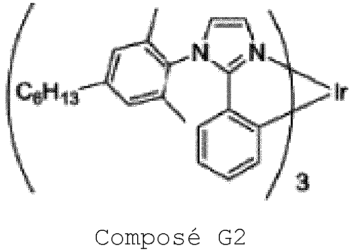


On a dissous le composé de polymère P4 à une concentration de 0,25 % en poids dans du 2,2,3,3,4,4,5,5-octafluoro-1-pentanol ; on a déposé à la tournette la solution de 2,2,3,3,4,4,5,5-octafluoro-1-pentanol résultante sur la couche électroluminescente pour former un film avec une épaisseur de 10 nm, et on a chauffé le film à 130 °C pendant 10 minutes sous atmosphère d'azote gazeux, pour ainsi former une couche de transport d'électrons ;
On a placé le substrat portant la couche de transport d'électrons formée sur celui-ci dans une machine de dépôt en phase vapeur, et on a réduit la pression à 1,0 x 10⁻⁴ Pa ou moins, puis on a déposé en phase vapeur, en tant que cathode, du fluorure de sodium avec une épaisseur d'environ 4 nm sur la couche électroluminescente, puis on a déposé en phase vapeur de l'aluminium avec une épaisseur d'environ 80 nm sur la couche de fluorure de sodium ; après le dépôt en phase vapeur, on a réalisé un scellage avec un substrat en verre, pour ainsi fabriquer un dispositif électroluminescent ;(c) On a attaché un substrat en verre avec un film d'ITO avec une épaisseur de 45 nm par un procédé de pulvérisation cathodique, pour former une anode ; sur l'anode, on a déposé à la tournette un agent d'injection de trous de type polythiophène-acide sulfonique AQ-1200 (fabriqué par Plectronics) pour former un film avec une épaisseur de 35 nm, et on a chauffé le film sur une plaque chaude à 170 °C pendant 15 minutes sous atmosphère d'air, pour ainsi former une couche d'injection de trous ;
On a dissous le composé de polymère P1 et le composé G2 tel que défini en (b) ci-avant (composé de polymère P1/composé G2 = 70 % en poids/30 % en poids) à une concentration de 0,5 % en poids dans du chlorobenzène ; on a déposé à la tournette la solution de chlorobenzène résultante sur la couche d'injection de trous pour former un film avec une épaisseur de 20 nm, et on a chauffé le film sur une plaque chaude à 180 °C pendant 60 minutes sous atmosphère d'azote gazeux, pour ainsi former une couche de transport de trous ; par le chauffage sur une plaque chaude à 180 °C pendant 60 minutes, le composé de polymère P1 devient un corps réticulé du composé de polymère P1 ;
On a dissous du 2,8-di(9H-carbazol-9-yl)dibenzo[b,d]thiophène (DCzDBT) (fabriqué par Luminescence Technology Corp) et le composé G2 tel que défini en (b) ci-avant (DCzDBT/composé G2 = 70 % en poids/30 % en poids) à une concentration de 2,0 % en poids dans du chlorobenzène ; on a déposé à la tournette la solution de chlorobenzène résultante sur la couche de transport de trous pour former un film avec une épaisseur de 60 nm, et on a chauffé le film à 130 °C pendant 10 minutes sous atmosphère d'azote gazeux, pour ainsi former une couche électroluminescente ;
On a dissous le composé de polymère P4 tel que défini en (b) ci-avant à une concentration de 0,25 % en poids dans du 2,2,3,3,4,4,5,5-octafluoro-1-pentanol ; on a déposé à la tournette la solution de 2,2,3,3,4,4,5,5-octafluoro-1-pentanol résultante sur la couche électroluminescente pour former un film avec une épaisseur de 10 nm, et on a chauffé le film à 130 °C pendant 10 minutes sous atmosphère d'azote gazeux, pour ainsi former une couche de transport d'électrons ;
On a placé le substrat portant la couche de transport d'électrons formée sur celui-ci dans une machine de dépôt en phase vapeur, et on a réduit la pression à 1,0 x 10⁻⁴ Pa ou moins, puis on a déposé en phase vapeur, en tant que cathode, du fluorure de sodium avec une épaisseur d'environ 4 nm sur la couche électroluminescente, puis on a déposé en phase vapeur de l'aluminium avec une épaisseur d'environ 80 nm sur la couche de fluorure de sodium ; après le dépôt en phase vapeur, on a réalisé un scellage avec un substrat en verre, pour ainsi fabriquer un dispositif électroluminescent ;(d) On a attaché un substrat en verre avec un film d'ITO avec une épaisseur de 45 nm par un procédé de pulvérisation cathodique, pour former une anode ; sur l'anode, on a déposé à la tournette un agent d'injection de trous de type polythiophène-acide sulfonique AQ-1200 (fabriqué par Plectronics) pour former un film avec une épaisseur de 35 nm, et on a chauffé le film sur une plaque chaude à 170 °C pendant 15 minutes sous atmosphère d'air, pour ainsi former une couche d'injection de trous ;
On a dissous le composé de polymère P1 et le composé G2 tel que défini en (b) ci-avant (composé de polymère P1/composé G2 = 85 % en poids/15 % en poids) à une concentration de 0,5 % en poids dans du chlorobenzène ; on a déposé à la tournette la solution de chlorobenzène résultante sur la couche d'injection de trous pour former un film avec une épaisseur de 20 nm, et on a chauffé le film sur une plaque chaude à 180 °C pendant 60 minutes sous atmosphère d'azote gazeux, pour ainsi former une couche de transport de trous ; par le chauffage sur une plaque chaude à 180 °C pendant 60 minutes, le composé de polymère P1 devient un corps réticulé du composé de polymère P1;
On a dissous le composé de polymère P4 tel que défini en (b) ci-avant à une concentration de 0,25 % en poids dans du 2,2,3,3,4,4,5,5-octafluoro-1-pentanol ; on a déposé à la tournette la solution de 2,2,3,3,4,4,5,5-octafluoro-1-pentanol résultante sur la couche électroluminescente pour former un film avec une épaisseur de 10 nm, et on a chauffé le film à 130 °C pendant 10 minutes sous atmosphère d'azote gazeux, pour ainsi former une couche de transport d'électrons ;
On a placé le substrat portant la couche de transport d'électrons formée sur celui-ci dans une machine de dépôt en phase vapeur, et on a réduit la pression à 1,0 x 10⁻⁴ Pa ou moins, puis on a déposé en phase vapeur, en tant que cathode, du fluorure de sodium avec une épaisseur d'environ 4 nm sur la couche électroluminescente, puis on a déposé en phase vapeur de l'aluminium avec une épaisseur d'environ 80 nm sur la couche de fluorure de sodium ; après le dépôt en phase vapeur, on a réalisé un scellage avec un substrat en verre, pour ainsi fabriquer un dispositif électroluminescent ;(e) On a attaché un substrat en verre avec un film d'ITO avec une épaisseur de 45 nm par un procédé de pulvérisation cathodique, pour former une anode ; sur l'anode, on a déposé à la tournette un agent d'injection de trous de type polythiophène-acide sulfonique AQ-1200 (fabriqué par Plectronics) pour former un film avec une épaisseur de 35 nm, et on a chauffé le film sur une plaque chaude à 170 °C pendant 15 minutes sous atmosphère d'air, pour ainsi former une couche d'injection de trous ;
On a dissous le composé de polymère P1 tel que défini en (b) ci-avant, le composé G1 et le composé G3 tels que définis en (d) ci-avant (composé de polymère P1/composé G1/composé G3 = 95 % en poids/3 % en poids/2 % en poids) à une concentration de 0,5 % en poids dans du chlorobenzène ; on a déposé à la tournette la solution de chlorobenzène résultante sur la couche d'injection de trous pour former un film avec une épaisseur de 20 nm, et on a chauffé le film sur une plaque chaude à 180 °C pendant 60 minutes sous atmosphère d'azote gazeux, pour ainsi former une couche de transport de trous ; par le chauffage sur une plaque chaude à 180 °C pendant 60 minutes, le composé de polymère P1 devient un corps réticulé du composé de polymère P1;
On a dissous du 2,8-di(9H-carbazol-9-yl)dibenzo[b,d]thiophène (DCzDBT) (fabriqué par Luminescence Technology Corp), le composé G2 tel que défini en (b) ci-avant, le composé G1 et le composé G3 tels que définis en (d) ci-avant (DCzDBT/composé G2/composé G1/composé G3 = 69 % en poids/30 % en poids/0,6 % en poids/0,4 % en poids) à une concentration de 2,0 % en poids dans du chlorobenzène ; on a déposé à la tournette la solution de chlorobenzène résultante sur la couche de transport de trous pour former un film avec une épaisseur de 60 nm, et on a chauffé le film à 130 °C pendant 10 minutes sous atmosphère d'azote gazeux, pour ainsi former une couche électroluminescente ;
On a dissous le composé de polymère P4 tel que défini en (b) ci-avant à une concentration de 0,25 % en poids dans du 2,2,3,3,4,4,5,5-octafluoro-1-pentanol ; on a déposé à la tournette la solution de 2,2,3,3,4,4,5,5-octafluoro-1-pentanol résultante sur la couche électroluminescente pour former un film avec une épaisseur de 10 nm, et on a chauffé le film à 130 °C pendant 10 minutes sous atmosphère d'azote gazeux, pour ainsi former une couche de transport d'électrons ;
On a placé le substrat portant la couche de transport d'électrons formée sur celui-ci dans une machine de dépôt en phase vapeur, et on a réduit la pression à 1,0 x 10⁻⁴ Pa ou moins, puis on a déposé en phase vapeur, en tant que cathode, du fluorure de sodium avec une épaisseur d'environ 4 nm sur la couche électroluminescente, puis on a déposé en phase vapeur de l'aluminium avec une épaisseur d'environ 80 nm sur la couche de fluorure de sodium ; après le dépôt en phase vapeur, on a réalisé un scellage avec un substrat en verre, pour ainsi fabriquer un dispositif électroluminescent ;(f) On a attaché un substrat en verre avec un film d'ITO avec une épaisseur de 45 nm par un procédé de pulvérisation cathodique, pour former une anode ; sur l'anode, on a déposé à la tournette un agent d'injection de trous de type polythiophène-acide sulfonique AQ-1200 (fabriqué par Plectronics) pour former un film avec une épaisseur de 35 nm, et on a chauffé le film sur une plaque chaude à 170 °C pendant 15 minutes sous atmosphère d'air, pour ainsi former une couche d'injection de trous ;
On a dissous le composé de polymère P1 tel que défini en (b) ci-avant, le composé G1 et le composé G3 tels que définis en (d) ci-avant (composé de polymère P1/composé G1/composé G3 = 90 % en poids/6 % en poids/4 % en poids) à une concentration de 0,5 % en poids dans du chlorobenzène ; on a déposé à la tournette la solution de chlorobenzène résultante sur la couche d'injection de trous pour former un film avec une épaisseur de 20 nm, et on a chauffé le film sur une plaque chaude à 180 °C pendant 60 minutes sous atmosphère d'azote gazeux, pour ainsi former une couche de transport de trous ; par le chauffage sur une plaque chaude à 180 °C pendant 60 minutes, le composé de polymère P1 devient un corps réticulé du composé de polymère P1;
On a dissous du 2,8-di(9H-carbazol-9-yl)dibenzo[b,d]thiophène (DCzDBT) (fabriqué par Luminescence Technology Corp), le composé G2 tel que défini en (b) ci-avant, le composé G1 et le composé G3 tels que définis en (d) ci-avant (DCzDBT/composé G2/composé G1/composé G3 = 69 % en poids/30 % en poids/0,6 % en poids/0,4 % en poids) à une concentration de 2,0 % en poids dans du chlorobenzène ; on a déposé à la tournette la solution de chlorobenzène résultante sur la couche de transport de trous pour former un film avec une épaisseur de 60 nm, et on a chauffé le film à 130 °C pendant 10 minutes sous atmosphère d'azote gazeux, pour ainsi former une couche électroluminescente ;
On a dissous le composé de polymère P4 tel que défini en (b) ci-avant à une concentration de 0,25 % en poids dans du 2,2,3,3,4,4,5,5-octafluoro-1-pentanol ; on a déposé à la tournette la solution de 2,2,3,3,4,4,5,5-octafluoro-1-pentanol résultante sur la couche électroluminescente pour former un film avec une épaisseur de 10 nm, et on a chauffé le film à 130 °C pendant 10 minutes sous atmosphère d'azote gazeux, pour ainsi former une couche de transport d'électrons ;
On a placé le substrat portant la couche de transport d'électrons formée sur celui-ci dans une machine de dépôt en phase vapeur, et on a réduit la pression à 1,0 x 10⁻⁴ Pa ou moins, puis on a déposé en phase vapeur, en tant que cathode, du fluorure de sodium avec une épaisseur d'environ 4 nm sur la couche électroluminescente, puis on a déposé en phase vapeur de l'aluminium avec une épaisseur d'environ 80 nm sur la couche de fluorure de sodium ; après le dépôt en phase vapeur, on a réalisé un scellage avec un substrat en verre, pour ainsi fabriquer un dispositif électroluminescent ;(g) On a attaché un substrat en verre avec un film d'ITO avec une épaisseur de 45 nm par un procédé de pulvérisation cathodique, pour former une anode ; sur l'anode, on a déposé à la tournette un agent d'injection de trous de type polythiophène-acide sulfonique AQ-1200 (fabriqué par Plectronics) pour former un film avec une épaisseur de 35 nm, et on a chauffé le film sur une plaque chaude à 170 °C pendant 15 minutes sous atmosphère d'air, pour ainsi former une couche d'injection de trous ;
On a dissous le composé de polymère P1 tel que défini en (b) ci-avant à une concentration de 0,5 % en poids dans du chlorobenzène ; on a déposé à la tournette la solution de chlorobenzène résultante sur la couche d'injection de trous pour former un film avec une épaisseur de 20 nm, et on a chauffé le film sur une plaque chaude à 180 °C pendant 60 minutes sous atmosphère d'azote gazeux, pour ainsi former une couche de transport de trous ; par le chauffage sur une plaque chaude à 180 °C pendant 60 minutes, le composé de polymère P1 devient un corps réticulé du composé de polymère P1 ;
On a dissous du 2,8-di(9H-carbazol-9-yl)dibenzo[b,d]thiophène (DCzDBT) (fabriqué par Luminescence Technology Corp), le composé G2 tel que défini en (b) ci-avant (DCzDBT/composé G2 = 70 % en poids/30 % en poids) à une concentration de 2,0 % en poids dans du chlorobenzène ; on a déposé à la tournette la solution de chlorobenzène résultante sur la couche de transport de trous pour former un film avec une épaisseur de 60 nm, et on a chauffé le film à 130 °C pendant 10 minutes sous atmosphère d'azote gazeux, pour ainsi former une couche électroluminescente ;
On a dissous le composé de polymère P4 tel que défini en (b) ci-avant à une concentration de 0,25 % en poids dans du 2,2,3,3,4,4,5,5-octafluoro-1-pentanol ; on a déposé à la tournette la solution de 2,2,3,3,4,4,5,5-octafluoro-1-pentanol résultante sur la couche électroluminescente pour former un film avec une épaisseur de 10 nm, et on a chauffé le film à 130 °C pendant 10 minutes sous atmosphère d'azote gazeux, pour ainsi former une couche de transport d'électrons ;
On a placé le substrat portant la couche de transport d'électrons formée sur celui-ci dans une machine de dépôt en phase vapeur, et on a réduit la pression à 1,0 x 10⁻⁴ Pa ou moins, puis on a déposé en phase vapeur, en tant que cathode, du fluorure de sodium avec une épaisseur d'environ 4 nm sur la couche électroluminescente, puis on a déposé en phase vapeur de l'aluminium avec une épaisseur d'environ 80 nm sur la couche de fluorure de sodium ; après le dépôt en phase vapeur, on a réalisé un scellage avec un substrat en verre, pour ainsi fabriquer un dispositif électroluminescent ;(h) On a attaché un substrat en verre avec un film d'ITO avec une épaisseur de 45 nm par un procédé de pulvérisation cathodique, pour former une anode ; sur l'anode, on a déposé à la tournette un agent d'injection de trous de type polythiophène-acide sulfonique AQ-1200 (fabriqué par Plectronics) pour former un film avec une épaisseur de 35 nm, et on a chauffé le film sur une plaque chaude à 170 °C pendant 15 minutes sous atmosphère d'air, pour ainsi former une couche d'injection de trous ;
On a dissous le composé de polymère P1 tel que défini en (b) ci-avant à une concentration de 0,5 % en poids dans du chlorobenzène ; on a déposé à la tournette la solution de chlorobenzène résultante sur la couche d'injection de trous pour former un film avec une épaisseur de 20 nm, et on a chauffé le film sur une plaque chaude à 180 °C pendant 60 minutes sous atmosphère d'azote gazeux, pour ainsi former une couche de transport de trous ; par le chauffage sur une plaque chaude à 180 °C pendant 60 minutes, le composé de polymère P1 devient un corps réticulé du composé de polymère P1 ;
On a dissous du 2,8-di(9H-carbazol-9-yl)dibenzo[b,d]thiophène (DCzDBT) (fabriqué par Luminescence Technology Corp), le composé G2 tel que défini en (b) ci-avant, le composé G1 et le composé G3 tels que définis en (d) ci-avant (DCzDBT/composé G2/composé G1/composé G3 = 69 % en poids/30 % en poids/0,6 % en poids/0,4 % en poids) à une concentration de 2,0 % en poids dans du chlorobenzène ; on a déposé à la tournette la solution de chlorobenzène résultante sur la couche de transport de trous pour former un film avec une épaisseur de 60 nm, et on a chauffé le film à 130 °C pendant 10 minutes sous atmosphère d'azote gazeux, pour ainsi former une couche électroluminescente ;
On a dissous le composé de polymère P4 tel que défini en (b) ci-avant à une concentration de 0,25 % en poids dans du 2,2,3,3,4,4,5,5-octafluoro-1-pentanol ; on a déposé à la tournette la solution de 2,2,3,3,4,4,5,5-octafluoro-1-pentanol résultante sur la couche électroluminescente pour former un film avec une épaisseur de 10 nm, et on a chauffé le film à 130 °C pendant 10 minutes sous atmosphère d'azote gazeux, pour ainsi former une couche de transport d'électrons ;
On a placé le substrat portant la couche de transport d'électrons formée sur celui-ci dans une machine de dépôt en phase vapeur, et on a réduit la pression à 1,0 x 10⁻⁴ Pa ou moins, puis on a déposé en phase vapeur, en tant que cathode, du fluorure de sodium avec une épaisseur d'environ 4 nm sur la couche électroluminescente, puis on a déposé en phase vapeur de l'aluminium avec une épaisseur d'environ 80 nm sur la couche de fluorure de sodium ; après le dépôt en phase vapeur, on a réalisé un scellage avec un substrat en verre, pour ainsi fabriquer un dispositif électroluminescent ;(i) On a formé une anode par la fourniture d'un film d'ITO ayant une épaisseur de 45 nm par un procédé de pulvérisation cathodique sur un substrat en verre ; sur l'anode, on a appliqué par un procédé de dépôt à la tournette du AQ-1200 (fabriqué par Plectronics Inc.) en tant qu'agent d'injection de trous à base de polythiophène-acide sulfonique pour former un film ayant une épaisseur de 35 nm, puis on l'a chauffé sur une plaque chaude pendant 15 minutes à 170 °C dans une atmosphère ambiante, pour ainsi former une couche d'injection de trous ;


 (j) On a formé une anode par la fourniture d'un film d'ITO ayant une épaisseur de 45 nm par un procédé de pulvérisation cathodique sur un substrat en verre ; sur l'anode, on a appliqué par un procédé de dépôt à la tournette du AQ-1200 (fabriqué par Plectronics Inc.) en tant qu'agent d'injection de trous à base de polythiophène-acide sulfonique pour former un film ayant une épaisseur de 35 nm, puis on l'a chauffé sur une plaque chaude pendant 15 minutes à 170 °C dans une atmosphère ambiante, pour ainsi former une couche d'injection de trous ;
On a dissous le composé de polymère 1 tel que défini en (i) ci-avant dans du xylène à une concentration de 0,6 % en poids ; on a utilisé la solution de xylène résultante pour former un film ayant une épaisseur de 20 nm par dépôt à la tournette sur la couche d'injection de trous, puis on l'a chauffé sur une plaque chaude pendant 60 minutes à 180 °C dans une atmosphère d'azote gazeux, pour ainsi former une première couche électroluminescente ;
On a préparé une deuxième encre par dissolution du composé de polymère 5 tel que défini en (i) ci-avant dans du 2,2,3,3,4,4,5,5-octafluoro-1-pentanol à une concentration de 0,25 % en poids ; on a appliqué la deuxième encre sur la deuxième couche électroluminescente par un procédé de dépôt à la tournette pour former un film ayant une épaisseur de 10 nm, puis on l'a chauffé sur une plaque chaude pendant 10 minutes à 130 °C dans une atmosphère d'azote gazeux, pour ainsi former une couche de transport d'électrons ; sur la couche de transport d'électrons, on a évaporé, en tant que cathode, du fluorure de sodium pour lui donner une épaisseur d'environ 7 nm, puis on a évaporé de l'aluminium pour lui donner une épaisseur d'environ 120 nm, pour ainsi fabriquer un dispositif électroluminescent ;(k) On a formé une anode par la fourniture d'un film d'ITO ayant une épaisseur de 45 nm par un procédé de pulvérisation cathodique sur un substrat en verre ; sur l'anode, on a appliqué par un procédé de dépôt à la tournette du AQ-1200 (fabriqué par Plectronics Inc.) en tant qu'agent d'injection de trous à base de polythiophène-acide sulfonique pour former un film ayant une épaisseur de 35 nm, puis on l'a chauffé sur une plaque chaude pendant 15 minutes à 170 °C dans une atmosphère ambiante, pour ainsi former une couche d'injection de trous ;
On a dissous le composé de polymère P1 tel que défini en (i) ci-avant dans du xylène à une concentration de 0,6 % en poids ; on a utilisé la solution de xylène résultante pour former un film ayant une épaisseur de 20 nm par dépôt à la tournette sur la couche d'injection de trous, puis on l'a chauffé sur une plaque chaude pendant 60 minutes à 180 °C dans une atmosphère d'azote gazeux, pour ainsi former une première couche électroluminescente ;
On a préparé une deuxième encre par dissolution du composé de polymère 5 tel que défini en (i) ci-avant dans du 2,2,3,3,4,4,5,5-octafluoro-1-pentanol à une concentration de 0,25 % en poids ; on a appliqué la deuxième encre sur la deuxième couche électroluminescente par un procédé de dépôt à la tournette pour former un film ayant une épaisseur de 10 nm, puis on l'a chauffé sur une plaque chaude pendant 10 minutes à 130 °C dans une atmosphère d'azote gazeux, pour ainsi former une couche de transport d'électrons ; sur la couche de transport d'électrons, on a évaporé, en tant que cathode, du fluorure de sodium pour lui donner une épaisseur d'environ 7 nm, puis on a évaporé de l'aluminium pour lui donner une épaisseur d'environ 120 nm, pour ainsi fabriquer un dispositif électroluminescent. - Dispositif électroluminescent selon la revendication 1, dans lequel le composé phosphorescent n'est pas un composé phosphorescent représenté par l'une quelconque de la formule COM-17, B2 ou B3 suivante :


- Dispositif électroluminescent selon la revendication 1, dans lequel le composé phosphorescent de formule (1) est un composé phosphorescent représenté par les formules COM-18 à COM-28 suivantes :


- Dispositif électroluminescent selon l'une quelconque des revendications 1 à 3, dans lequel la valeur de (Y1 x 1000)/X1 est de 0,65 ou plus.
- Dispositif électroluminescent selon l'une quelconque des revendications 1 à 4, dans lequel au moins l'un choisi dans le groupe constitué par R11A, R12A , R13A, R21A , R22A , R23A et R24A est un groupe représenté par la formule (D-A) ou (D-B) :

 mDA1, mDA2 et mDA3 représentent chacun indépendamment un entier de 0 ou plus ;GDA représente un atome d'azote, un groupe hydrocarboné aromatique ou un groupe hétérocyclique, et ces groupes ont chacun éventuellement un substituant ;ArDA1, ArDA2 et ArDA3 représentent chacun indépendamment un groupe arylène ou un groupe hétérocyclique divalent, et ces groupes ont chacun éventuellement un substituant ; et lorsqu'une pluralité de ArDA1, ArDA2 et ArDA3 sont présents, ils peuvent être identiques ou différents à chaque occurrence ; etTDA représente un groupe aryle ou un groupe hétérocyclique monovalent, et ces groupes ont chacun éventuellement un substituant ; et la pluralité de TDA peuvent être identiques ou différents ; et* représente une position de liaison, et
 mDA1, mDA2, mDA3, mDA4, mDA5, mDA6 et mDA7 représentent chacun indépendamment un entier de 0 ou plus ;GDA représente un atome d'azote, un groupe hydrocarboné aromatique ou un groupe hétérocyclique, et ces groupes ont chacun éventuellement un substituant, et la pluralité de GDA peuvent être identiques ou différents ;ArDA1, ArDA2, ArDA3, ArDA4, ArDA5, ArDA6 et ArDA7 représentent chacun indépendamment un groupe arylène ou un groupe hétérocyclique divalent, et ces groupes ont chacun éventuellement un substituant ; et lorsqu'une pluralité de ArDA1, ArDA2, ArDA3, ArDA4, ArDA5, ArDA6 et ArDA7 sont présents, ils peuvent être identiques ou différents à chaque occurrence ; etTDA représente un groupe aryle ou un groupe hétérocyclique monovalent, et ces groupes ont chacun éventuellement un substituant, et la pluralité de TDA peuvent être identiques ou différents ; et* représente une position de liaison.
 - Dispositif électroluminescent selon l'une quelconque des revendications 1, 4 ou 5, dans lequel le composé phosphorescent est représenté par la formule (1-1) ou (1-2) :

- Dispositif électroluminescent selon l'une quelconque des revendications 1 à 6, dans lequel le composé de polymère réticulable comprend un motif constitutif représenté par la formule (2) :
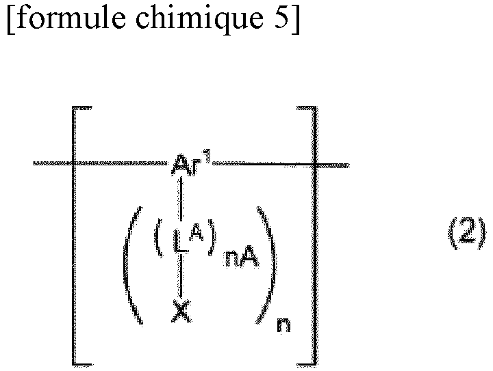 nA représente un entier de 0 à 5, et n représente 1 ou 2 ;Ar1 représente un groupe hydrocarboné aromatique ou un groupe hétérocyclique, et ces groupes ont chacun éventuellement un substituant ;LA représente un groupe alkylène, un groupe cycloalkylène, un groupe arylène, un groupe hétérocyclique divalent, un groupe représenté par -NR'-, un atome d'oxygène ou un atome de soufre, et ces groupes ont chacun éventuellement un substituant ; R' représente un atome d'hydrogène, un groupe alkyle, un groupe cycloalkyle, un groupe aryle ou un groupe hétérocyclique monovalent, et ces groupes ont chacun éventuellement un substituant : et lorsqu'une pluralité de LA sont présents, ils peuvent être identiques ou différents ; etX représente un groupe réticulable choisi dans le groupe A de groupes réticulables, et lorsqu'une pluralité de X sont présents, ils peuvent être identiques ou différents.
 - Dispositif électroluminescent selon l'une quelconque des revendications 1 à 7, dans lequel le composé de polymère réticulable comprend un motif constitutif représenté par la formule (3) :
 mA représente un entier de 0 à 5, m représente 1 à 4, c représente 0 ou 1, et lorsqu'une pluralité de mA sont présents, ils peuvent être identiques ou différents ;Ar3 représente un groupe hydrocarboné aromatique, un groupe hétérocyclique ou un groupe dans lequel au moins un cycle hydrocarboné aromatique et au moins un cycle hétérocyclique sont liés directement l'un à l'autre, et ces groupes ont chacun éventuellement un substituant ;Ar2 et Ar4 représentent chacun indépendamment un groupe arylène ou un groupe hétérocyclique divalent, et ces groupes ont chacun éventuellement un substituant ;chacun de Ar2, Ar3 et Ar4 peut être lié directement ou via un atome d'oxygène ou un atome de soufre à un groupe qui est différent de ce groupe et qui est attaché à l'atome d'azote auquel ce groupe est attaché, pour ainsi former un cycle ;KA représente un groupe alkylène, un groupe cycloalkylène, un groupe arylène, un groupe hétérocyclique divalent, un groupe représenté par -NR"-, un atome d'oxygène ou un atome de soufre, et ces groupes ont chacun éventuellement un substituant ; R" représente un atome d'hydrogène, un groupe alkyle, un groupe cycloalkyle, un groupe aryle ou un groupe hétérocyclique monovalent, et ces groupes ont chacun éventuellement un substituant ; et lorsqu'une pluralité de KA sont présents, ils peuvent être identiques ou différents ; etX' représente un groupe réticulable choisi dans le groupe A de groupes réticulables, un atome d'hydrogène, un groupe alkyle, un groupe cycloalkyle, un groupe aryle ou un groupe hétérocyclique monovalent, et ces groupes ont chacun éventuellement un substituant ; et lorsqu'une pluralité de X' sont présents, ils peuvent être identiques ou différents ; à condition qu'au moins un X' soit un groupe réticulable choisi dans le groupe A de groupes réticulables.
 - Dispositif électroluminescent selon l'une quelconque des revendications 1 à 8, dans lequel la première couche organique comprend en outre un composé de polymère comprenant un motif constitutif représenté par la formule (Y) :
[formule chimique 8] -⁅ArY1⁆- (Y)
où ArY1 représente un groupe arylène, un groupe hétérocyclique divalent ou un groupe divalent dans lequel au moins un groupe arylène et au moins un groupe hétérocyclique divalent sont liés directement l'un à l'autre, et ces groupes ont chacun éventuellement un substituant. - Dispositif électroluminescent selon l'une quelconque des revendications 1 à 8, dans lequel la première couche organique comprend en outre un composé représenté par la formule (H-1) :
 ArH1 et ArH2 représentent chacun indépendamment un groupe aryle ou un groupe hétérocyclique monovalent, et ces groupes ont chacun éventuellement un substituant ;nH1 et nH2 représentent chacun indépendamment 0 ou 1 ; lorsqu'une pluralité de nH1 sont présents, ils peuvent être identiques ou différents ; et lorsqu'une pluralité de nH2 sont présents, ils peuvent être identiques ou différents ;nH3 représente un entier de 0 ou plus ;LH1 représente un groupe arylène, un groupe hétérocyclique divalent ou un groupe représenté par -[C(RH11)2]nH11-, et ces groupes ont chacun éventuellement un substituant ; et lorsqu'une pluralité de LH1 sont présents, ils peuvent être identiques ou différents ;nH11 représente un entier de 1 à 10 ; RH11 représente un atome d'hydrogène, un groupe alkyle, un groupe cycloalkyle, un groupe alcoxy, un groupe cycloalcoxy, un groupe aryle ou un groupe hétérocyclique monovalent, et ces groupes ont chacun éventuellement un substituant ; la pluralité de RH11 peuvent être identiques ou différents et peuvent être combinés ensemble pour former un cycle conjointement aux atomes de carbone auxquels ils sont attachés ;LH2 représente un groupe représenté par -N(-LH21-RH21)- ; et lorsqu'une pluralité de LH2 sont présents, ils peuvent être identiques ou différents ; etLH21 représente une liaison simple, un groupe arylène ou un groupe hétérocyclique divalent, et ces groupes ont chacun éventuellement un substituant ; et RH21 représente un atome d'hydrogène, un groupe alkyle, un groupe cycloalkyle, un groupe aryle ou un groupe hétérocyclique monovalent, et ces groupes ont chacun éventuellement un substituant.
Applications Claiming Priority (2)
| Application Number | Priority Date | Filing Date | Title |
|---|---|---|---|
| JP2014201264 | 2014-09-30 | ||
| PCT/JP2015/077113 WO2016052337A1 (fr) | 2014-09-30 | 2015-09-25 | Élément électroluminescent |
Publications (3)
| Publication Number | Publication Date |
|---|---|
| EP3203543A1 EP3203543A1 (fr) | 2017-08-09 |
| EP3203543A4 EP3203543A4 (fr) | 2018-06-06 |
| EP3203543B1 true EP3203543B1 (fr) | 2020-05-13 |
Family
ID=55630374
Family Applications (1)
| Application Number | Title | Priority Date | Filing Date |
|---|---|---|---|
| EP15846617.7A Active EP3203543B1 (fr) | 2014-09-30 | 2015-09-25 | Élément électroluminescent |
Country Status (6)
| Country | Link |
|---|---|
| US (1) | US20170222163A1 (fr) |
| EP (1) | EP3203543B1 (fr) |
| JP (1) | JP6715182B2 (fr) |
| KR (1) | KR20170066442A (fr) |
| CN (1) | CN107078223B (fr) |
| WO (1) | WO2016052337A1 (fr) |
Families Citing this family (3)
| Publication number | Priority date | Publication date | Assignee | Title |
|---|---|---|---|---|
| JP6822363B2 (ja) * | 2016-09-29 | 2021-01-27 | 住友化学株式会社 | 発光素子 |
| JP6836908B2 (ja) | 2017-01-10 | 2021-03-03 | 住友化学株式会社 | 有機デバイスの製造方法 |
| JP7346015B2 (ja) * | 2017-09-06 | 2023-09-19 | 住友化学株式会社 | 発光素子 |
Family Cites Families (23)
| Publication number | Priority date | Publication date | Assignee | Title |
|---|---|---|---|---|
| US6821645B2 (en) * | 1999-12-27 | 2004-11-23 | Fuji Photo Film Co., Ltd. | Light-emitting material comprising orthometalated iridium complex, light-emitting device, high efficiency red light-emitting device, and novel iridium complex |
| JP3929690B2 (ja) * | 1999-12-27 | 2007-06-13 | 富士フイルム株式会社 | オルトメタル化イリジウム錯体からなる発光素子材料、発光素子および新規イリジウム錯体 |
| JP4890669B2 (ja) * | 2000-03-13 | 2012-03-07 | Tdk株式会社 | 有機el素子 |
| US8440324B2 (en) * | 2005-12-27 | 2013-05-14 | E I Du Pont De Nemours And Company | Compositions comprising novel copolymers and electronic devices made with such compositions |
| JP4946923B2 (ja) * | 2007-03-07 | 2012-06-06 | 三菱化学株式会社 | 有機電界発光素子 |
| KR101323557B1 (ko) * | 2008-02-15 | 2013-10-29 | 미쓰비시 가가꾸 가부시키가이샤 | 공액 폴리머, 불용화 폴리머, 유기 전계 발광 소자 재료, 유기 전계 발광 소자용 조성물, 폴리머의 제조 방법, 유기 전계 발광 소자, 유기 el 디스플레이, 및 유기 el 조명 |
| WO2009123269A1 (fr) * | 2008-04-02 | 2009-10-08 | 三菱化学株式会社 | Composé polymère, composé polymère réticulé produit par réticulation du composé polymère, composition pour élément électroluminescent organique, élément électroluminescent organique, affichage el organique, et éclairage el organique |
| JP5491796B2 (ja) * | 2008-08-11 | 2014-05-14 | 三菱化学株式会社 | 電荷輸送性ポリマー、有機電界発光素子用組成物、有機電界発光素子、有機elディスプレイ及び有機el照明 |
| EP2492988B1 (fr) * | 2009-10-22 | 2018-12-26 | Sumitomo Chemical Company, Limited | Élément électroluminescent organique |
| JP2012151266A (ja) * | 2011-01-19 | 2012-08-09 | Konica Minolta Holdings Inc | 有機エレクトロルミネッセンス素子、表示装置、照明装置及び有機エレクトロルミネッセンス素子材料 |
| JP5742581B2 (ja) * | 2011-08-16 | 2015-07-01 | コニカミノルタ株式会社 | 有機エレクトロルミネッセンス素子、表示装置、照明装置 |
| WO2013102992A1 (fr) * | 2012-01-05 | 2013-07-11 | 出光興産株式会社 | Matériau pour élément organique électroluminescent et élément utilisant ce matériau |
| JP2013216789A (ja) * | 2012-04-09 | 2013-10-24 | Mitsubishi Chemicals Corp | 重合体、有機電界発光素子材料、有機電界発光素子用組成物、有機電界発光素子、有機el表示装置及び有機el照明 |
| JP6244653B2 (ja) * | 2012-05-16 | 2017-12-13 | 住友化学株式会社 | 高分子化合物およびそれを用いた発光素子 |
| JP5929512B2 (ja) * | 2012-05-24 | 2016-06-08 | コニカミノルタ株式会社 | 有機エレクトロルミネッセンス素子、その製造方法及び照明装置 |
| JP2014033008A (ja) * | 2012-08-01 | 2014-02-20 | Sumitomo Chemical Co Ltd | 電荷受容性組成物及び有機エレクトロルミネッセンス素子 |
| JP6531386B2 (ja) * | 2013-12-26 | 2019-06-19 | 住友化学株式会社 | 発光素子およびそれに用いる高分子化合物 |
| EP3131131B1 (fr) * | 2014-04-09 | 2021-08-25 | Sumitomo Chemical Company Limited | Élément électroluminescent et composition utilisée dedans |
| JP6675304B2 (ja) * | 2014-04-25 | 2020-04-01 | 住友化学株式会社 | 発光素子 |
| JP5867580B2 (ja) * | 2014-06-04 | 2016-02-24 | 住友化学株式会社 | 発光素子 |
| US20180022990A1 (en) * | 2015-02-03 | 2018-01-25 | Sumitomo Chemical Company, Limited | Composition and light emitting device using the same |
| JP6256630B2 (ja) * | 2015-04-24 | 2018-01-10 | 住友化学株式会社 | 発光素子および該発光素子に用いる組成物 |
| EP3306694B1 (fr) * | 2015-05-29 | 2020-08-12 | Sumitomo Chemical Company, Ltd. | Élément électroluminescent et son procédé de fabrication |
-
2015
- 2015-09-25 WO PCT/JP2015/077113 patent/WO2016052337A1/fr not_active Ceased
- 2015-09-25 US US15/515,225 patent/US20170222163A1/en not_active Abandoned
- 2015-09-25 KR KR1020177010473A patent/KR20170066442A/ko not_active Ceased
- 2015-09-25 JP JP2016551976A patent/JP6715182B2/ja not_active Expired - Fee Related
- 2015-09-25 EP EP15846617.7A patent/EP3203543B1/fr active Active
- 2015-09-25 CN CN201580050590.1A patent/CN107078223B/zh not_active Expired - Fee Related
Non-Patent Citations (1)
| Title |
|---|
| None * |
Also Published As
| Publication number | Publication date |
|---|---|
| CN107078223B (zh) | 2019-03-29 |
| US20170222163A1 (en) | 2017-08-03 |
| JPWO2016052337A1 (ja) | 2017-07-20 |
| EP3203543A4 (fr) | 2018-06-06 |
| CN107078223A (zh) | 2017-08-18 |
| KR20170066442A (ko) | 2017-06-14 |
| WO2016052337A1 (fr) | 2016-04-07 |
| EP3203543A1 (fr) | 2017-08-09 |
| JP6715182B2 (ja) | 2020-07-01 |
Similar Documents
| Publication | Publication Date | Title |
|---|---|---|
| EP3154101B1 (fr) | Élément électroluminescent | |
| US9741934B2 (en) | Polymer compound and light emitting device using the same | |
| EP3133660B1 (fr) | Composition et élément électroluminescent utilisant cette composition | |
| EP3131131B1 (fr) | Élément électroluminescent et composition utilisée dedans | |
| KR20180104086A (ko) | 조성물, 인광 발광성 화합물 및 발광 소자 | |
| US10497885B2 (en) | Light emitting device and composition used for this light emitting device | |
| EP3199565B1 (fr) | Composé polymère et élément électroluminescent l'utilisant | |
| JP6694262B2 (ja) | 発光素子 | |
| EP3883345A1 (fr) | Procédé de fabrication de film | |
| EP3171673B1 (fr) | Procédé de fabrication d'élément électroluminescent | |
| EP3361521B1 (fr) | Élément électroluminescent | |
| EP3203543A1 (fr) | Élément électroluminescent | |
| JP6596918B2 (ja) | 発光素子 |
Legal Events
| Date | Code | Title | Description |
|---|---|---|---|
| STAA | Information on the status of an ep patent application or granted ep patent |
Free format text: STATUS: THE INTERNATIONAL PUBLICATION HAS BEEN MADE |
|
| PUAI | Public reference made under article 153(3) epc to a published international application that has entered the european phase |
Free format text: ORIGINAL CODE: 0009012 |
|
| STAA | Information on the status of an ep patent application or granted ep patent |
Free format text: STATUS: REQUEST FOR EXAMINATION WAS MADE |
|
| 17P | Request for examination filed |
Effective date: 20170427 |
|
| AK | Designated contracting states |
Kind code of ref document: A1 Designated state(s): AL AT BE BG CH CY CZ DE DK EE ES FI FR GB GR HR HU IE IS IT LI LT LU LV MC MK MT NL NO PL PT RO RS SE SI SK SM TR |
|
| AX | Request for extension of the european patent |
Extension state: BA ME |
|
| DAV | Request for validation of the european patent (deleted) | ||
| DAX | Request for extension of the european patent (deleted) | ||
| A4 | Supplementary search report drawn up and despatched |
Effective date: 20180509 |
|
| RIC1 | Information provided on ipc code assigned before grant |
Ipc: C08G 61/12 20060101ALI20180503BHEP Ipc: H01L 51/50 20060101AFI20180503BHEP Ipc: C09K 11/02 20060101ALI20180503BHEP Ipc: C09K 11/06 20060101ALI20180503BHEP Ipc: H01L 51/00 20060101ALI20180503BHEP |
|
| STAA | Information on the status of an ep patent application or granted ep patent |
Free format text: STATUS: EXAMINATION IS IN PROGRESS |
|
| 17Q | First examination report despatched |
Effective date: 20190425 |
|
| GRAP | Despatch of communication of intention to grant a patent |
Free format text: ORIGINAL CODE: EPIDOSNIGR1 |
|
| STAA | Information on the status of an ep patent application or granted ep patent |
Free format text: STATUS: GRANT OF PATENT IS INTENDED |
|
| INTG | Intention to grant announced |
Effective date: 20191210 |
|
| GRAS | Grant fee paid |
Free format text: ORIGINAL CODE: EPIDOSNIGR3 |
|
| GRAA | (expected) grant |
Free format text: ORIGINAL CODE: 0009210 |
|
| STAA | Information on the status of an ep patent application or granted ep patent |
Free format text: STATUS: THE PATENT HAS BEEN GRANTED |
|
| AK | Designated contracting states |
Kind code of ref document: B1 Designated state(s): AL AT BE BG CH CY CZ DE DK EE ES FI FR GB GR HR HU IE IS IT LI LT LU LV MC MK MT NL NO PL PT RO RS SE SI SK SM TR |
|
| REG | Reference to a national code |
Ref country code: GB Ref legal event code: FG4D |
|
| REG | Reference to a national code |
Ref country code: CH Ref legal event code: EP |
|
| REG | Reference to a national code |
Ref country code: DE Ref legal event code: R096 Ref document number: 602015052869 Country of ref document: DE |
|
| REG | Reference to a national code |
Ref country code: AT Ref legal event code: REF Ref document number: 1271388 Country of ref document: AT Kind code of ref document: T Effective date: 20200615 |
|
| REG | Reference to a national code |
Ref country code: LT Ref legal event code: MG4D |
|
| REG | Reference to a national code |
Ref country code: NL Ref legal event code: MP Effective date: 20200513 |
|
| PG25 | Lapsed in a contracting state [announced via postgrant information from national office to epo] |
Ref country code: SE Free format text: LAPSE BECAUSE OF FAILURE TO SUBMIT A TRANSLATION OF THE DESCRIPTION OR TO PAY THE FEE WITHIN THE PRESCRIBED TIME-LIMIT Effective date: 20200513 Ref country code: LT Free format text: LAPSE BECAUSE OF FAILURE TO SUBMIT A TRANSLATION OF THE DESCRIPTION OR TO PAY THE FEE WITHIN THE PRESCRIBED TIME-LIMIT Effective date: 20200513 Ref country code: NO Free format text: LAPSE BECAUSE OF FAILURE TO SUBMIT A TRANSLATION OF THE DESCRIPTION OR TO PAY THE FEE WITHIN THE PRESCRIBED TIME-LIMIT Effective date: 20200813 Ref country code: FI Free format text: LAPSE BECAUSE OF FAILURE TO SUBMIT A TRANSLATION OF THE DESCRIPTION OR TO PAY THE FEE WITHIN THE PRESCRIBED TIME-LIMIT Effective date: 20200513 Ref country code: GR Free format text: LAPSE BECAUSE OF FAILURE TO SUBMIT A TRANSLATION OF THE DESCRIPTION OR TO PAY THE FEE WITHIN THE PRESCRIBED TIME-LIMIT Effective date: 20200814 Ref country code: IS Free format text: LAPSE BECAUSE OF FAILURE TO SUBMIT A TRANSLATION OF THE DESCRIPTION OR TO PAY THE FEE WITHIN THE PRESCRIBED TIME-LIMIT Effective date: 20200913 Ref country code: PT Free format text: LAPSE BECAUSE OF FAILURE TO SUBMIT A TRANSLATION OF THE DESCRIPTION OR TO PAY THE FEE WITHIN THE PRESCRIBED TIME-LIMIT Effective date: 20200914 |
|
| PG25 | Lapsed in a contracting state [announced via postgrant information from national office to epo] |
Ref country code: LV Free format text: LAPSE BECAUSE OF FAILURE TO SUBMIT A TRANSLATION OF THE DESCRIPTION OR TO PAY THE FEE WITHIN THE PRESCRIBED TIME-LIMIT Effective date: 20200513 Ref country code: HR Free format text: LAPSE BECAUSE OF FAILURE TO SUBMIT A TRANSLATION OF THE DESCRIPTION OR TO PAY THE FEE WITHIN THE PRESCRIBED TIME-LIMIT Effective date: 20200513 Ref country code: RS Free format text: LAPSE BECAUSE OF FAILURE TO SUBMIT A TRANSLATION OF THE DESCRIPTION OR TO PAY THE FEE WITHIN THE PRESCRIBED TIME-LIMIT Effective date: 20200513 Ref country code: BG Free format text: LAPSE BECAUSE OF FAILURE TO SUBMIT A TRANSLATION OF THE DESCRIPTION OR TO PAY THE FEE WITHIN THE PRESCRIBED TIME-LIMIT Effective date: 20200813 |
|
| REG | Reference to a national code |
Ref country code: AT Ref legal event code: MK05 Ref document number: 1271388 Country of ref document: AT Kind code of ref document: T Effective date: 20200513 |
|
| PG25 | Lapsed in a contracting state [announced via postgrant information from national office to epo] |
Ref country code: AL Free format text: LAPSE BECAUSE OF FAILURE TO SUBMIT A TRANSLATION OF THE DESCRIPTION OR TO PAY THE FEE WITHIN THE PRESCRIBED TIME-LIMIT Effective date: 20200513 Ref country code: NL Free format text: LAPSE BECAUSE OF FAILURE TO SUBMIT A TRANSLATION OF THE DESCRIPTION OR TO PAY THE FEE WITHIN THE PRESCRIBED TIME-LIMIT Effective date: 20200513 |
|
| PG25 | Lapsed in a contracting state [announced via postgrant information from national office to epo] |
Ref country code: RO Free format text: LAPSE BECAUSE OF FAILURE TO SUBMIT A TRANSLATION OF THE DESCRIPTION OR TO PAY THE FEE WITHIN THE PRESCRIBED TIME-LIMIT Effective date: 20200513 Ref country code: ES Free format text: LAPSE BECAUSE OF FAILURE TO SUBMIT A TRANSLATION OF THE DESCRIPTION OR TO PAY THE FEE WITHIN THE PRESCRIBED TIME-LIMIT Effective date: 20200513 Ref country code: CZ Free format text: LAPSE BECAUSE OF FAILURE TO SUBMIT A TRANSLATION OF THE DESCRIPTION OR TO PAY THE FEE WITHIN THE PRESCRIBED TIME-LIMIT Effective date: 20200513 Ref country code: DK Free format text: LAPSE BECAUSE OF FAILURE TO SUBMIT A TRANSLATION OF THE DESCRIPTION OR TO PAY THE FEE WITHIN THE PRESCRIBED TIME-LIMIT Effective date: 20200513 Ref country code: EE Free format text: LAPSE BECAUSE OF FAILURE TO SUBMIT A TRANSLATION OF THE DESCRIPTION OR TO PAY THE FEE WITHIN THE PRESCRIBED TIME-LIMIT Effective date: 20200513 Ref country code: IT Free format text: LAPSE BECAUSE OF FAILURE TO SUBMIT A TRANSLATION OF THE DESCRIPTION OR TO PAY THE FEE WITHIN THE PRESCRIBED TIME-LIMIT Effective date: 20200513 Ref country code: SM Free format text: LAPSE BECAUSE OF FAILURE TO SUBMIT A TRANSLATION OF THE DESCRIPTION OR TO PAY THE FEE WITHIN THE PRESCRIBED TIME-LIMIT Effective date: 20200513 Ref country code: AT Free format text: LAPSE BECAUSE OF FAILURE TO SUBMIT A TRANSLATION OF THE DESCRIPTION OR TO PAY THE FEE WITHIN THE PRESCRIBED TIME-LIMIT Effective date: 20200513 |
|
| REG | Reference to a national code |
Ref country code: DE Ref legal event code: R097 Ref document number: 602015052869 Country of ref document: DE |
|
| PG25 | Lapsed in a contracting state [announced via postgrant information from national office to epo] |
Ref country code: PL Free format text: LAPSE BECAUSE OF FAILURE TO SUBMIT A TRANSLATION OF THE DESCRIPTION OR TO PAY THE FEE WITHIN THE PRESCRIBED TIME-LIMIT Effective date: 20200513 Ref country code: SK Free format text: LAPSE BECAUSE OF FAILURE TO SUBMIT A TRANSLATION OF THE DESCRIPTION OR TO PAY THE FEE WITHIN THE PRESCRIBED TIME-LIMIT Effective date: 20200513 |
|
| PLBE | No opposition filed within time limit |
Free format text: ORIGINAL CODE: 0009261 |
|
| STAA | Information on the status of an ep patent application or granted ep patent |
Free format text: STATUS: NO OPPOSITION FILED WITHIN TIME LIMIT |
|
| 26N | No opposition filed |
Effective date: 20210216 |
|
| REG | Reference to a national code |
Ref country code: CH Ref legal event code: PL |
|
| GBPC | Gb: european patent ceased through non-payment of renewal fee |
Effective date: 20200925 |
|
| PG25 | Lapsed in a contracting state [announced via postgrant information from national office to epo] |
Ref country code: SI Free format text: LAPSE BECAUSE OF FAILURE TO SUBMIT A TRANSLATION OF THE DESCRIPTION OR TO PAY THE FEE WITHIN THE PRESCRIBED TIME-LIMIT Effective date: 20200513 |
|
| REG | Reference to a national code |
Ref country code: BE Ref legal event code: MM Effective date: 20200930 |
|
| PG25 | Lapsed in a contracting state [announced via postgrant information from national office to epo] |
Ref country code: LU Free format text: LAPSE BECAUSE OF NON-PAYMENT OF DUE FEES Effective date: 20200925 |
|
| PG25 | Lapsed in a contracting state [announced via postgrant information from national office to epo] |
Ref country code: FR Free format text: LAPSE BECAUSE OF NON-PAYMENT OF DUE FEES Effective date: 20200930 |
|
| PG25 | Lapsed in a contracting state [announced via postgrant information from national office to epo] |
Ref country code: CH Free format text: LAPSE BECAUSE OF NON-PAYMENT OF DUE FEES Effective date: 20200930 Ref country code: BE Free format text: LAPSE BECAUSE OF NON-PAYMENT OF DUE FEES Effective date: 20200930 Ref country code: GB Free format text: LAPSE BECAUSE OF NON-PAYMENT OF DUE FEES Effective date: 20200925 Ref country code: IE Free format text: LAPSE BECAUSE OF NON-PAYMENT OF DUE FEES Effective date: 20200925 Ref country code: LI Free format text: LAPSE BECAUSE OF NON-PAYMENT OF DUE FEES Effective date: 20200930 |
|
| PG25 | Lapsed in a contracting state [announced via postgrant information from national office to epo] |
Ref country code: TR Free format text: LAPSE BECAUSE OF FAILURE TO SUBMIT A TRANSLATION OF THE DESCRIPTION OR TO PAY THE FEE WITHIN THE PRESCRIBED TIME-LIMIT Effective date: 20200513 Ref country code: MT Free format text: LAPSE BECAUSE OF FAILURE TO SUBMIT A TRANSLATION OF THE DESCRIPTION OR TO PAY THE FEE WITHIN THE PRESCRIBED TIME-LIMIT Effective date: 20200513 Ref country code: CY Free format text: LAPSE BECAUSE OF FAILURE TO SUBMIT A TRANSLATION OF THE DESCRIPTION OR TO PAY THE FEE WITHIN THE PRESCRIBED TIME-LIMIT Effective date: 20200513 |
|
| PG25 | Lapsed in a contracting state [announced via postgrant information from national office to epo] |
Ref country code: MK Free format text: LAPSE BECAUSE OF FAILURE TO SUBMIT A TRANSLATION OF THE DESCRIPTION OR TO PAY THE FEE WITHIN THE PRESCRIBED TIME-LIMIT Effective date: 20200513 Ref country code: MC Free format text: LAPSE BECAUSE OF FAILURE TO SUBMIT A TRANSLATION OF THE DESCRIPTION OR TO PAY THE FEE WITHIN THE PRESCRIBED TIME-LIMIT Effective date: 20200513 |
|
| PGFP | Annual fee paid to national office [announced via postgrant information from national office to epo] |
Ref country code: DE Payment date: 20220809 Year of fee payment: 8 |
|
| REG | Reference to a national code |
Ref country code: DE Ref legal event code: R079 Ref document number: 602015052869 Country of ref document: DE Free format text: PREVIOUS MAIN CLASS: H01L0051500000 Ipc: H10K0050000000 |
|
| REG | Reference to a national code |
Ref country code: DE Ref legal event code: R119 Ref document number: 602015052869 Country of ref document: DE |
|
| PG25 | Lapsed in a contracting state [announced via postgrant information from national office to epo] |
Ref country code: DE Free format text: LAPSE BECAUSE OF NON-PAYMENT OF DUE FEES Effective date: 20240403 |