EP3204949B1 - Von der umgebung separiertes becken für verbrauchte brennelemente - Google Patents
Von der umgebung separiertes becken für verbrauchte brennelemente Download PDFInfo
- Publication number
- EP3204949B1 EP3204949B1 EP15849173.8A EP15849173A EP3204949B1 EP 3204949 B1 EP3204949 B1 EP 3204949B1 EP 15849173 A EP15849173 A EP 15849173A EP 3204949 B1 EP3204949 B1 EP 3204949B1
- Authority
- EP
- European Patent Office
- Prior art keywords
- pool
- liner
- interstitial space
- sidewalls
- spent fuel
- Prior art date
- Legal status (The legal status is an assumption and is not a legal conclusion. Google has not performed a legal analysis and makes no representation as to the accuracy of the status listed.)
- Active
Links
Images





Classifications
-
- G—PHYSICS
- G21—NUCLEAR PHYSICS; NUCLEAR ENGINEERING
- G21C—NUCLEAR REACTORS
- G21C19/00—Arrangements for treating, for handling, or for facilitating the handling of, fuel or other materials which are used within the reactor, e.g. within its pressure vessel
- G21C19/02—Details of handling arrangements
- G21C19/06—Magazines for holding fuel elements or control elements
- G21C19/07—Storage racks; Storage pools
-
- G—PHYSICS
- G21—NUCLEAR PHYSICS; NUCLEAR ENGINEERING
- G21C—NUCLEAR REACTORS
- G21C13/00—Pressure vessels; Containment vessels; Containment in general
- G21C13/10—Means for preventing contamination in the event of leakage, e.g. double wall
-
- G—PHYSICS
- G21—NUCLEAR PHYSICS; NUCLEAR ENGINEERING
- G21C—NUCLEAR REACTORS
- G21C17/00—Monitoring; Testing ; Maintaining
- G21C17/002—Detection of leaks
-
- G—PHYSICS
- G01—MEASURING; TESTING
- G01M—TESTING STATIC OR DYNAMIC BALANCE OF MACHINES OR STRUCTURES; TESTING OF STRUCTURES OR APPARATUS, NOT OTHERWISE PROVIDED FOR
- G01M3/00—Investigating fluid-tightness of structures
-
- Y—GENERAL TAGGING OF NEW TECHNOLOGICAL DEVELOPMENTS; GENERAL TAGGING OF CROSS-SECTIONAL TECHNOLOGIES SPANNING OVER SEVERAL SECTIONS OF THE IPC; TECHNICAL SUBJECTS COVERED BY FORMER USPC CROSS-REFERENCE ART COLLECTIONS [XRACs] AND DIGESTS
- Y02—TECHNOLOGIES OR APPLICATIONS FOR MITIGATION OR ADAPTATION AGAINST CLIMATE CHANGE
- Y02E—REDUCTION OF GREENHOUSE GAS [GHG] EMISSIONS, RELATED TO ENERGY GENERATION, TRANSMISSION OR DISTRIBUTION
- Y02E30/00—Energy generation of nuclear origin
- Y02E30/30—Nuclear fission reactors
Definitions
- the present invention generally relates to storage of nuclear fuel assemblies, and more particularly to an improved spent fuel pool for wet storage of such fuel assemblies.
- a spent fuel pool (sometimes, two or more) is an integral part of every nuclear power plant.
- standalone wet storage facilities have also been built to provide additional storage capacity for the excess fuel discharged by the reactors.
- An autonomous wet storage facility that serves one or more reactor units is sometimes referred to by the acronym AFR meaning "Away-from-Reactor.” While most countries have added to their in-plant used fuel storage capacity by building dry storage facilities, the French nuclear program has been the most notable user of AFR storage.
- the spent fuel pool stores the fuel irradiated in the plant's reactor in a deep pool of water.
- the pool is typically 12,19 m (40 feet) deep with upright Fuel Racks positioned on its bottom slab. Under normal storage conditions, there is at least 7,62 m (25 feet) of water cover on top of the fuel to ensure that the dose at the pool deck level is acceptably low for the plant workers.
- Fuel pools at most (but not all) nuclear plants are at grade level, which is desirable from the standpoint of structural capacity of the reinforced concrete structure that forms the deep pond of water.
- the liners have generally served reliably at most nuclear plants, but isolated cases of water seepage of pool water have been reported. Because the pool's water bears radioactive contaminants (most of it carried by the crud deposited on the fuel during its "burn” in the reactor), leaching out of the pool water to the plant's substrate, and possibly to the underground water, is evidently inimical to public health and safety. To reduce the probability of pool water reaching the ground water, the local environment and hence some AFR pools have adopted the pool-in-pool design wherein the fuel pool is enclosed by a secondary outer pool filled with clean water. In the dual-pool design, any leakage of water from the contaminated pool will occur into the outer pool, which serves as the barrier against ground water contamination.
- the dual pool design has several unattractive aspects, viz.: (1) the structural capacity of the storage system is adversely affected by two reinforced concrete containers separated from each other except for springs and dampers that secure their spacing; (2) there is a possibility that the outer pool may leak along with the inner pool, defeating both barriers and allowing for contaminated water to reach the external environment; and (3) the dual-pool design significantly increases the cost of the storage system.
- nuclear spent fuel pools are disclosed in documents DE3430180 A1 , JPS5757233 A or JPS63250600 A .
- the present invention provides an environmentally sequestered spent fuel pool system and a related method for detecting leakage from a nuclear spent fuel pool according to the amended set of claims.
- any reference to direction or orientation is merely intended for convenience of description and is not intended in any way to limit the scope of the present invention.
- Relative terms such as “lower,” “upper,” “horizontal,” “vertical,”, “above,” “below,” “up,” “down,” “top” and “bottom” as well as derivative thereof (e.g., “horizontally,” “downwardly,” “upwardly,” etc.) should be construed to refer to the orientation as then described or as shown in the drawing under discussion. These relative terms are for convenience of description only and do not require that the apparatus be constructed or operated in a particular orientation.
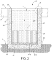
- an environmentally sequestered spent fuel pool system includes a spent fuel pool 40 comprising a plurality of vertical sidewalls 41 rising upwards from an adjoining substantially horizontal base wall or slab 42 (recognizing that some slope may intentionally be provided in the upper surface of the bottom wall for drainage toward a low point if the pool is to be emptied and rinsed/decontaminated at some time and due to installation tolerances).
- the base slab 42 and sidewalls 41 may be formed of reinforced concrete in one non-limiting embodiment.
- the fuel pool base slab 42 may be formed in and rest on the soil sub-grade 26 the top surface of which defines grade G. In this embodiment illustrated in the present application, the sidewalls are elevated above grade. In other possible embodiments contemplated, the base slab 42 and sidewalls 41 may alternatively be buried in sub-grade 26 which surrounds the outer surfaces of the sidewalls. Either arrangement may be used and does not limit of the invention.
- the spent fuel pool 40 may have a rectilinear shape in top plan view.
- Four sidewalls 41 may be provided in which the pool has an elongated rectangular shape (in top plan view) with two longer opposing sidewalls and two shorter opposing sidewalls (e.g. end walls).
- Other configurations of the fuel pool 40 are possible such as square shapes, other polygonal shapes, and non-polygonal shapes.
- the sidewalls 41 and base slab 42 of the spent fuel pool 40 define a cavity 43 configured to hold cooling pool water W and a plurality of submerged nuclear spent fuel assembly storage racks 27 holding fuel bundles or assemblies 28 each containing multiple individual nuclear spent fuel rods.
- the storage racks 27 are disposed on the base slab 42 in typical fashion.
- the spent fuel pool 40 extends from an operating deck 22 surrounding the spent fuel pool 40 downwards to a sufficient depth D1 to submerge the fuel assemblies 28 (see, e.g. FIG. 6 ) beneath the surface level S of the pool water W for proper radiation shielding purposes.
- the fuel pool may have a depth such that at least 3,09 m (10 feet) of water is present above the top of the fuel assembly.
- a nuclear fuel assembly storage rack 27 is shown in FIGS. 2 and 3 , and further described in commonly assigned U.S. Patent Application No. 14/367,705 filed June 20, 1014.
- the storage rack 27 contains a plurality of vertically elongated individual cells as shown each configured for holding a fuel assembly 28 comprising a plurality of individual nuclear fuel rods.
- An elongated fuel assembly 28 is shown in FIG. 6 holding multiple fuel rods 28a and further described in commonly assigned U.S. Patent Application No. 14/413,807 filed July 9, 2013 .
- Typical fuel assemblies 28 for a pressurized water reactor (PWR) may each hold over 150 fuel rods in 10x10 to 17x17 fuel rod grid arrays per assembly.
- the assemblies may typically be on the order of approximately 4, 27 m (14 feet) high weighing about 635-680 kg (1400-1500 pounds)each.
- the substantially horizontal operating deck 22 that circumscribes the sidewalls 41 and pool 40 on all sides in one embodiment may be formed of steel and/or reinforced concrete.
- the surface level of pool water W (i.e. liquid coolant) in the pool 40 may be spaced below the operating deck 22 by a sufficient amount to prevent spillage onto the deck during fuel assembly loading or unloading operations and to account to seismic event.
- the surface of the operating deck 22 may be at least 1,52 m (5 feet)above the maximum 100 year flood level for the site in one embodiment.
- the spent fuel pool 40 extending below the operating deck level may be approximately 12,19 m (40 feet) or more deep (e.g. 12,80 m (42 feet) in one embodiment).
- the fuel pool is long enough to accommodate as many spent fuel assemblies as required.
- the fuel pool 40 may be about 18,29 m (60 feet) wide. There is sufficient operating deck space around the pool to provide space for the work crew and for staging necessary tools and equipment for the facility's maintenance. There may be no penetrations in the spent fuel pool 40 within the bottom 9,14 m (30 feet) of depth to prevent accidental draining of water and uncovering of the spent fuel.
- a spent fuel pool liner system comprising a double liner is provided to minimize the risk of pool water leakage to the environment.
- the liner system is further designed to accommodate cooling water leakage collection and detection/monitoring to indicate a leakage condition caused by a breach in the integrity of the liner system.
- the liner system comprises a first outer liner 60 separated from a second inner liner 61 by an interstitial space 62 formed between the liners.
- An outside surface of liner 60 is disposed against or at least proximate to the inner surface 63 of the fuel pool sidewalls 41 and opposing inside surface is disposed proximate to the interstitial space 62 and outside surface of liner 61.
- the inside surface of liner 61 is contacted and wetted by the fuel pool water W. It bears noting that placement of liner 60 against liner 61 without spacers therebetween provides a natural interstitial space of sufficient width to allow the space and any pool leakage there-into to be evacuated by a vacuum system, as further described herein.
- each liner 60, 61 may be made of any suitable metal which is preferably resistant to corrosion, including without limitation stainless steel, aluminum, or other.
- each liner may be comprised of multiple substantially flat metal plates which are seal welded together along their peripheral edges to form a continuous liner system encapsulating the sidewalls 41 and base slab 42 of the spent fuel pool 40.
- the inner and outer liners 61, 60 may have the same or different thicknesses (measured horizontally or vertically between major opposing surfaces of the liners depending on the position of the liners). In one embodiment, the thicknesses may be the same. In some instances, however, it may be preferable that the inner liner 61 be thicker than the outer liner 60 for potential impact resistant when initially loading empty fuel storage racks 27 into the spent fuel pool 40.
- the outer and inner liners 60, 61 extend along the vertical sidewalls 41 of the spent fuel pool 40 and completely across the horizontal base slab 42 in one embodiment to completely cover the wetted surface area of the pool.
- the horizontal sections of liners 60b, 61b on the base slab 42 may be joined to the vertical sections 60a, 61a along the sidewalls 41 of the pool 40 by welding.
- FIG. 4 shows one or many possible constructions of the bottom liner joint 64 comprising the use of seal welds 65 (e.g.
- the joint 64 is configured and arranged to fluidly connect the horizontal interstitial space 64 between horizontal liner sections 60b, 61b to the vertical interstitial space 64 between vertical liner sections 60a, 61a for reasons explained elsewhere herein.
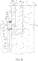
- the top liner joint 65 in one non-limiting embodiment between the top terminal edges 60c, 61c of the vertical liner sections 60a, 61a is shown in the detail of FIG. 5 .
- the top of the spent fuel pool 40 is equipped with a substantially thick metal embedment plate 70 which circumscribes the entire perimeter of the fuel pool.
- the embedment plate 70 may be continuous in one embodiment and extends horizontally along the entire inner surface 63 of the sidewalls 41 at the top portion of the sidewalls.
- the embedment plate 70 has an exposed portion of the inner vertical side facing the pool which extends above the top terminal ends 60c, 61c of the inner and outer liners 60, 61.
- the opposing outer vertical side of the plate 70 is embedded entirely into the sidewalls 41.
- a top surface 71 of the embedment plate 70 that faces upwards may be substantially flush with the top surface 44 of the sidewalls 41 to form a smooth transition therebetween. In other possible implementations, the top surface 71 may extend above the top surface 44 of the sidewalls.
- the embedment plate 70 extends horizontal outward from the fuel pool 40 for a distance into and less than the lateral width of the sidewalls 41 as shown.
- the embedment plate 70 has a horizontal thickness greater than the horizontal thickness of the inner liner 61, outer liner 60, and in some embodiments both the inner and outer liners combined.
- the top embedment plate 70 is embedded into the top surface 44 of the concrete sidewalls 41 has a sufficient vertical depth or height to allow the top terminal edges 60c, 61c of liners 60, 61 (i.e. sections 60a and 61a respectively) to be permanently joined to the plate.
- the top terminal edges of liners 60, 61 terminate at distances D2 and D1 respectively below a top surface 71 of the embedment plate 70 (which in one embodiment may be flush with the top surface of the pool sidewalls 41 as shown).
- Distance D1 is less than D2 such that the outer liner 60 is vertical shorter in height than the inner liner 61.
- the embedment plate 70 has a bottom end which terminates below the top terminal edges 60c, 61c of the liners 60, 61 to facilitate for welding the liners to the plate.
- the embedment plate 70 may be formed of a suitable corrosion resistant metal such as stainless steel, aluminum, or another metal which preferably is compatible for welding to the metal used to construct the outer and inner pool liners 60, 61 without requiring dissimilar metal welding.
- a suitable corrosion resistant metal such as stainless steel, aluminum, or another metal which preferably is compatible for welding to the metal used to construct the outer and inner pool liners 60, 61 without requiring dissimilar metal welding.
- the top terminal edges 60c, 61c of inner and outer liners 60, 61 are vertically staggered arranged and are separately seal welded to the top embedment plate 70 independently of each other.
- a seal weld 66 couples the top terminal edge 61c of liner 61 to the exposed portion of the inner vertical side of the embedment plate 70.
- a second seal weld 67 couples the top terminal edge 60c of liner 60 also to the exposed portion of the inner vertical side of the embedment plate 70 at a location below and spaced vertical apart from seal weld 66. This defines a completely and hermetically sealed enclosed flow plenum 68 that horizontal circumscribes the entire perimeter of the spent fuel pool 40 in one embodiment.
- the flow plenum 68 is in fluid communication with the interstitial space 62 as shown.
- One vertical side of the flow plenum is bounded by a portion of inner liner 61 and the opposing vertical side of the plenum is bounded by the inner vertical side of the top embedment plate 70.
- the top flow plenum 68 may be continuous or discontinuous in some embodiments. Where discontinuous, it is preferable that a flow passageway 105 in the top embedment plate 70 be provided for each section of the separate passageways.
- Seal welds 66 and 67 may be any type of suitable weld needed to seal the liners 60, 61 to the top embedment plate 70.
- Backer plates, bars, or other similar welding accessories may be used to make the welds as needed depending on the configuration and dimensions of the welds used. The invention is not limited by the type of weld.
- the outer and inner liners 60, 61 are sealably attached to the spent fuel pool 40 only at top embedment plate 70.
- the remaining portions of the liners below the embedment plate may be in abutting contact with the sidewalls 41 and base slab 42 without means for fixing the liners to these portions.
- At least the inner liner 61 has a height which preferably is higher than the anticipated highest water level (surface S) of the pool water W in one embodiment. If the water level happens to exceed that for some reason, the top embedment plate 70 will be wetted directly by the pool water and contain the fluid to prevent overflowing the pool onto the operating deck 22.
- a vapor extraction or vacuum system 100 is provided that is used to draw down the air pressure in the interstitial space between the outer and inner liners 60, 61 to a relatively high state of vacuum for leakage control and/or detection.
- FIG. 7 is a schematic diagram of one embodiment of a vacuum system 100.
- vacuum system 100 generally includes a vacuum pump 101 and a charcoal filter 102.
- Vacuum pump 101 may be any suitable commercially-available electric-driven vacuum pump capable of creating a vacuum or negative pressure within the interstitial space 62 between the pool liners 60 and 61.
- the vacuum pump 101 is fluidly connected to the interstitial space 68 via a suitable flow conduit 103 which is fluidly coupled to a telltale or flow passageway 105 extending from the top surface 71 of the top embedment plate 70 to the top flow plenum 68 formed between the pool liners 60 and 61.
- Flow conduit 103 may be formed of any suitable metallic or non-metallic tubing or piping capable of withstanding a vacuum.
- a suitably-configured fluid coupling 104 may be provided and sealed to the outlet end of the flow passageway 105 for connecting the flow conduit 103.
- the inlet end of the flow passageway penetrates the inner vertical side of top embedment plate 70 within the flow plenum 68.
- the flow passageway 105 and external flow conduit 103 provides a contiguous flow conduit that fluidly couples the flow plenum 68 to the vacuum pump 101.
- a one-way check valve is disposed between the flow plenum 105 and the suction inlet of the vacuum pump 101 to permit air and/or vapor to flow in a single direction from the liner system to the pump.
- the absolute pressure maintained by the vacuum system 100 in the interstitial space 62 between the liners 60, 61 preferably should be such that the bulk water temperature of the spent fuel pool 40 which is heated by waste decay heat generated from the fuel rods/assemblies is above the boiling temperature of water at the set pressure.
- set pressure The table below provides the boiling temperature of water at the level of vacuum in Pascal (Pa) (inches of mercury (Hg)) and represents some examples of set pressures that may be used.
- any significant rise in pressure would indicate potential leakage of water in the interstitial space 62 between the liners 60, 61. Because of sub-atmospheric conditions maintained by the vacuum pump 101 in the interstitial space, any water that may leak from the pool into this space through the inner liner 61 would evaporate, causing the pressure to rise which may be monitored and detected by a pressure sensor 104.
- the vacuum pump 101 preferably should be set to run and drive down the pressure in the interstitial space 62 to the "set pressure.”
- the vacuum pump 101 is operated to create a negative pressure (vacuum) in the interstitial space 62 of 6772 Pa (2 inches of Hg), the corresponding boiling point of water at that negative pressure is 101 degrees Fahrenheit (degrees F) from the above Table. If the bulk water temperature of pool water W in the spent fuel pool 40 were at any temperature above 101 degrees F and leakage occurred through the inner pool liner 61 into the interstitial space 62, the liquid leakage would immediately evaporate therein creating steam or vapor. The vacuum pump 101 withdraws the vapor through the flow plenum 68, flow passageway 105 in the top embedment plate 70, and flow conduit 103 (see, e.g. directional flow arrows of the water vapor in FIGS.
- Pressure sensor 104 disposed on the suction side of the pump 101 would detect a corresponding rise in pressure indicative of a potential leak in the liner system.
- the pressure sensor 104 may be operably linked to a control panel of a properly configured computer processor based plant monitoring system 107 which monitors and detects the pressure measured in the interstitial space 62 between the liners on a continuous or intermittent basis to alert operators of a potential pool leakage condition.
- plant monitoring systems are well known in the art without further elaboration.
- the extracted vapor in the exhaust or discharge from the vacuum pump 101 is routed through a suitable filtration device 102 such as a charcoal filter or other type of filter media before discharge to the atmosphere, thereby preventing release of any particulate contaminants to the environment.
- a suitable filtration device 102 such as a charcoal filter or other type of filter media
- the second outer liner 60 encapsulating the fuel pool provides a secondary barrier and line of defense to prevent direct leaking of pool water W into the environment.
- vapor extraction systems including a telltale passageway, vacuum pump, and filter combination with leakage monitoring/detection capabilities that may be provided.
- four independent systems may provide adequate redundancy.
- a third or even fourth layer of liner may be added to increase the number of barriers against leakage of pool water to the environment.
- a third layer in some instances may be used as a palliative measure if the leak tightness of the first inter-liner space could not, for whatever reason, be demonstrated by a high fidelity examination in the field such as helium spectroscopy.
Landscapes
- Physics & Mathematics (AREA)
- Engineering & Computer Science (AREA)
- Plasma & Fusion (AREA)
- General Engineering & Computer Science (AREA)
- High Energy & Nuclear Physics (AREA)
- Monitoring And Testing Of Nuclear Reactors (AREA)
Claims (11)
- Ein von der Umgebung separiertes Beckensystem für verbrauchte Brennelemente aufweisend:eine Fundamentplatte (42);eine Mehrzahl von vertikalen Seitenwänden (41), die sich von der Fundamentplatte (42) nach oben erstrecken und in die Fundamentplatte (42) übergehen, wobei die Seitenwände eine Umfassung bilden;eine zusammen von den Seitenwänden (41) und der Fundamentplatte (42) gebildete Kavität (43), die im Gebrauch Beckenwasser (W) hält;ein Beckenauskleidungssystem, das eine an die Seitenwände (41) angrenzende äußere Auskleidung (60) und eine an die äußere Auskleidung angrenzende innere Auskleidung (61) aufweist und im Gebrauch von dem Beckenwasser (W) benetzt wird, und das einen zwischen den Auskleidungen ausgebildeten Zwischenraum (62) aufweist;eine obere Einsatzplatte (70), die die Umfassung des Beckens an einer Oberseite der an die Kavität (43) angrenzenden Seitenwände (41) begrenzt;wobei die innere und äußere Auskleidung (61, 60) obere terminale Enden haben, die durch Versiegeln an der Einsatzplatte (70) befestigt sind;wobei das System dadurch gekennzeichnet ist, dass das System ferner aufweist:eine Strömungskammer (68), die an den oberen terminalen Kanten (61c, 60c) der inneren und äußeren Auskleidung (61, 60) entlang der Seitenwände (41) ausgebildet ist, wobei sich die Strömungskammer (68) mit dem Zwischenraum (62) in Fluidverbindung befindet, und einen Strömungsdurchgang (105), der durch die obere Einsatzplatte (70) ausgebildet ist, die sich mit der Strömungskammer in Fluidverbindung befindet, wobei der Strömungsdurchgang ein Auslassende hat, das eine Oberseite (71) der oberen Einsatzplatte durchdringt;wobei das System ferner aufweisteine Vakuumpumpe (101), die an die Strömungskammer (68) flüssigkeitsmäßig angeschlossen ist, wobei die Vakuumpumpe betreibbar ist, um den Zwischenraum (62) auf einen eingestellten negativen Druck zu evakuieren, der unterhalb des Atmosphärendrucks liegt;wobei die obere Einsatzplatte (70) die Umfassung des Beckens begrenzt, und die Einsatzplatte in die an die Kavität angrenzenden Seitenwände (41) eingesetzt ist;wobei die innere und äußere Auskleidung (61, 60) an der oberen Einsatzplatte (70) in einer gestaffelten Ausrichtung befestigt sind, um die Strömungskammer (68) auszubilden; undwobei die Vakuumpumpe (101) fluidmäßig durch die obere Einsatzplatte (70) an die Strömungskammer (68) angeschlossen ist;wobei die oberen terminalen Kanten (61c, 60c) der inneren und äußeren Auskleidung (61, 60) separat mit der oberen Einsatzplatte zur Ausbildung der Strömungskammer verschweißt sind.
- Das Beckensystem für verbrauchte Brennelemente nach Anspruch 1, wobei ein horizontaler Abschnitt der inneren und äußeren Auskleidung (61, 60) sich über die Fundamentplatte (42) erstreckt und die Fundamentplatte (42) zwischen den gegenüberliegenden Seitenwänden (41) abdeckt, wobei die horizontalen Abschnitte der inneren und äußeren Auskleidung und die die Seitenwände abdeckenden Abschnitte eine kontinuierliche Barriere bilden, die im Gebrauch das Beckenwasser (W) einkapseln.
- Das Beckensystem für verbrauchte Brennelemente nach Anspruch 1, wobei sich die Strömungskammer (68) um den gesamten Umfang des Beckens für verbrauchte Brennelemente erstreckt.
- Das Beckensystem für verbrauchte Brennelemente nach Anspruch 1, wobei die innere Auskleidung (61), die äußere Auskleidung (60) und die obere Einsatzplatte (70) aus demselben metallischen Material bestehen.
- Das Beckensystem für verbrauchte Brennelemente nach Anspruch 1 ferner aufweisend wenigstens ein Brennelemente-Lagerregal (27) aufweist, das auf der Fundamentplatte (42) ausgebildet ist, wobei das Lagerregal eine Mehrzahl von Zellen hat, die jeweils ein verbrauchtes Brennelement (28) hält, das Brennstäbe (28a) enthält.
- Das Becken für verbrauchte Brennelemente nach Anspruch 1, wobei der Strömungsdurchgang (105) die Vakuumpumpe (101) mit dem Zwischenraum (62) fluidmäßig verbindet.
- Das Becken für verbrauchte Brennelemente nach Anspruch 6 ferner aufweisend einen in einem Strömungskanal (103) angeordneten Drucksensor (104), der einen Sauganschluss der Vakuumpumpe (101) mit dem Strömungsdurchgang (105) fluidmäßig verbindet.
- Das Becken für verbrauchte Brennelemente nach Anspruch 1 ferner aufweisend ein auf einem Computerprozessor basierendes Anlagenüberwachungssystem (107), das zur Überwachung und zur Detektion eines in dem Zwischenraum (62) zwischen der inneren und äußeren Auskleidung (61, 62) gemessenen Drucks ausgebildet ist.
- Ein Verfahren zum Detektieren einer Leckage von einem Becken für verbrauchte Brennelemente nach Anspruch 1, wobei das Verfahren aufweist:Vorsehen des Beckens für verbrauchte Brennelemente aufweisend die Mehrzahl von Seitenwänden (41), die Fundamentplatte (42), die Kühlwasser (W) enthaltende Kavität (43) und das in der Kavität angeordnete Auskleidungssystem, das die äußere Auskleidung (60), die innere Auskleidung (61) und den Zwischenraum (62) zwischen der Auskleidung aufweist;Anordnen eines Brennelemente-Lagerregals (27) in dem Becken;Einsetzen wenigstens eines Brennelements (28) in das Lagerregal, wobei das Brennelement eine Mehrzahl von verbrauchten Brennstäben (28a) enthält;Erwärmen des Kühlwasser (W) in dem Becken auf eine erste Temperatur von der von den Brennstäben (28a) erzeugten Nachzerfallswärme;Ziehen eines Vakuums in dem Zwischenraum (62) mit der Vakuumpumpe (101) zu einem negativen Druck mit einer entsprechenden Siedepunkttemperatur, die kleiner als die erste Temperatur ist;Sammeln von Kühlwasser (W), das von dem Becken durch das Auskleidungssystem in den Zwischenraum (62) austritt;Umwandeln des austretenden Kühlwassers (W) in Dampf mittels Kochen; undExtrahieren des Dampfes aus dem Zwischenraum (62) mittels der Vakuumpumpe (101);wobei die Anwesenheit von Dampf in dem Zwischenraum (62) die Detektion eines Bruchs der Auskleidung erlaubt.
- Das Verfahren nach Anspruch 9 ferner aufweisend das Abführen des von der Vakuumpumpe (101) extrahierten Dampfs durch einen Kohlefilter, um die Kontaminierungen zu entfernen.
- Das Verfahren nach Anspruch 9 ferner aufweisend:Überwachen eines Drucks in dem Zwischenraum (62);Detektieren eines ersten Drucks in dem Zwischenraum (62) vor dem Sammeln des Kühlwassers (W), das von dem Becken durch das Auskleidungssystem in den Zwischenraum (62) austritt;Detektieren eines zweiten Drucks, der höher als der erste Druck ist, nach dem Sammeln von Kühlwasser, das von dem Becken durch das Auskleidungssystem in den Zwischenraum (62) austritt;wobei der zweite Druck mit einem Kühlwasserleckagezustand in Verbindung gebracht wird.
Applications Claiming Priority (2)
| Application Number | Priority Date | Filing Date | Title |
|---|---|---|---|
| US201462061089P | 2014-10-07 | 2014-10-07 | |
| PCT/US2015/054435 WO2016057636A1 (en) | 2014-10-07 | 2015-10-07 | Environmentally sequestered spent fuel pool |
Publications (3)
| Publication Number | Publication Date |
|---|---|
| EP3204949A1 EP3204949A1 (de) | 2017-08-16 |
| EP3204949A4 EP3204949A4 (de) | 2018-06-20 |
| EP3204949B1 true EP3204949B1 (de) | 2019-09-04 |
Family
ID=55633261
Family Applications (1)
| Application Number | Title | Priority Date | Filing Date |
|---|---|---|---|
| EP15849173.8A Active EP3204949B1 (de) | 2014-10-07 | 2015-10-07 | Von der umgebung separiertes becken für verbrauchte brennelemente |
Country Status (6)
| Country | Link |
|---|---|
| US (2) | US10468145B2 (de) |
| EP (1) | EP3204949B1 (de) |
| KR (1) | KR101956628B1 (de) |
| CN (1) | CN107077899B (de) |
| ES (1) | ES2762940T3 (de) |
| WO (1) | WO2016057636A1 (de) |
Families Citing this family (19)
| Publication number | Priority date | Publication date | Assignee | Title |
|---|---|---|---|---|
| US11515054B2 (en) | 2011-08-19 | 2022-11-29 | Holtec International | Method of retrofitting a spent nuclear fuel storage system |
| GB201510442D0 (en) * | 2015-06-15 | 2015-07-29 | Sensor Uk Ltd And Mwh Uk Ltd And Carlow Precast Mfg | Fluid retaining structure |
| US10366797B2 (en) * | 2015-09-17 | 2019-07-30 | Korea Atomic Energy Research Institute | System and method for preventing and monitoring leakage of water from tank liner |
| WO2018063022A1 (ru) * | 2016-09-30 | 2018-04-05 | Акционерное Общество "Научно-Исследовательский И Проектно-Конструкторский Институт Энергетических Технологий "Атомпроект" | Система контроля протечек жидкости из бассейна выдержки отработавшего ядерного топлива |
| CN106297923A (zh) * | 2016-10-11 | 2017-01-04 | 上海核工程研究设计院 | 一种双池设计的乏燃料水池 |
| US20240068749A1 (en) * | 2017-02-24 | 2024-02-29 | Holtec International | Air-cooled condenser, method for forming an axial flow baffle for a heat exchanger and/or method of cooling high level radioactive waste |
| US10847274B2 (en) * | 2017-02-24 | 2020-11-24 | Holtec International | Earthquake-resistant fuel storage rack system for fuel pools in nuclear plants |
| CN107511559B (zh) * | 2017-09-06 | 2020-10-20 | 中国核工业华兴建设有限公司 | 一种核电站双相不锈钢水池覆面安装方法及焊接工艺 |
| CN108172313A (zh) * | 2017-12-25 | 2018-06-15 | 中国建筑第二工程局有限公司 | 核电站用不锈钢水池及焊接方法 |
| JP7064991B2 (ja) * | 2018-07-30 | 2022-05-11 | 三菱重工業株式会社 | 燃料プールおよび燃料プールのライニング施工方法 |
| KR102196292B1 (ko) * | 2018-09-05 | 2020-12-29 | 한국수력원자력 주식회사 | 사용후 핵연료 냉각 장치 및 이를 이용한 사용후 핵연료 냉각 방법 |
| US10765033B1 (en) * | 2019-05-23 | 2020-09-01 | Microsoft Technology Licensing, Llc | Immersion cooling enclosures with insulating liners |
| CN110246600B (zh) * | 2019-07-11 | 2024-06-18 | 上海核工程研究设计院股份有限公司 | 一种全地下式紧凑型反应堆换料装置 |
| CN212434267U (zh) * | 2020-02-04 | 2021-01-29 | 中国海洋石油集团有限公司 | 一种放射性源库 |
| CN111564229B (zh) * | 2020-04-01 | 2023-11-24 | 中广核工程有限公司 | 核电站水池钢覆面的检漏方法 |
| KR20220011903A (ko) | 2020-07-22 | 2022-02-03 | 삼성전자주식회사 | 식기 세척기 |
| CN112967823B (zh) * | 2021-01-29 | 2023-05-23 | 中国原子能科学研究院 | 罩体组件及池式反应堆 |
| TWI766720B (zh) * | 2021-06-09 | 2022-06-01 | 洽興營造有限公司 | 地下化低階核廢料桶最終處置場 |
| CN117854765B (zh) * | 2024-01-10 | 2025-07-08 | 西安交通大学 | 核反应堆棒束通道内连续相流动阻力特性实验装置及方法 |
Family Cites Families (22)
| Publication number | Priority date | Publication date | Assignee | Title |
|---|---|---|---|---|
| US3444725A (en) * | 1967-04-06 | 1969-05-20 | Stone & Webster Eng Corp | Leak detecting and locating system for nuclear reactor containment vessels |
| US3430180A (en) * | 1967-05-18 | 1969-02-25 | Frank F Brown | Electrical swivel connector |
| FR2209983B1 (de) | 1972-12-13 | 1976-04-23 | Technigaz | |
| JPS5757233A (en) * | 1980-09-24 | 1982-04-06 | Hitachi Ltd | Apparatus for detecting leakage in pool lining and manufacture thereof |
| DE3430180A1 (de) * | 1984-08-16 | 1986-02-27 | Kraftwerk Union AG, 4330 Mülheim | Auskleidung fuer einen raum in einer kerntechnischen anlage |
| SU1408829A1 (ru) | 1985-05-11 | 1990-09-15 | Ленинградское Отделение Всесоюзного Государственного Научно-Исследовательского И Проектно-Изыскательского Института "Атомтеплоэлектропроект" | Способ возведени бассейна дл выдержки отработанного дерного топлива реакторного отделени атомной электростанции |
| JPS63250600A (ja) * | 1987-04-08 | 1988-10-18 | 株式会社東芝 | 放射性固体廃棄物処理装置 |
| US5102615A (en) * | 1990-02-22 | 1992-04-07 | Lou Grande | Metal-clad container for radioactive material storage |
| US5184504A (en) | 1990-05-30 | 1993-02-09 | Spring G Everett | Leak detection |
| FR2762132B1 (fr) | 1997-04-10 | 1999-06-18 | Commissariat Energie Atomique | Emballage de transport de colis dangereux, tels que des colis nucleaires de forte activite |
| US20040234338A1 (en) | 2003-05-19 | 2004-11-25 | Monroe Thomas K. | Secondary containment monitoring system |
| US7392690B2 (en) * | 2004-09-03 | 2008-07-01 | David D Russell | Systems and methods for monitoring the integrity of a tank |
| US7330526B2 (en) | 2005-03-25 | 2008-02-12 | Holtec International, Inc. | System and method of storing high level waste |
| US9443625B2 (en) | 2005-03-25 | 2016-09-13 | Holtec International, Inc. | Method of storing high level radioactive waste |
| EP2152460B1 (de) | 2007-05-04 | 2013-03-13 | Societat d'Obres i Treballs Subterranis del Pirineu (SOTS, S.L.) | Verfahren zur herstellung eines futters für ein becken, einen tank oder ein containergehäuse |
| JP4593601B2 (ja) * | 2007-08-03 | 2010-12-08 | キヤノンアネルバ株式会社 | 汚染物質除去方法、半導体製造方法、及び薄膜形成加工装置 |
| US8718221B2 (en) | 2009-12-16 | 2014-05-06 | Holtec International, Inc. | Method of transferring high level radioactive materials, and system for the same |
| WO2014036561A2 (en) | 2012-08-31 | 2014-03-06 | Holtec International, Inc. | System and method for storing and leak testing a radioactive materials storage canister |
| WO2014117082A1 (en) | 2013-01-25 | 2014-07-31 | Holtec International | Ventilated transfer cask with lifting feature |
| US8905259B2 (en) | 2010-08-12 | 2014-12-09 | Holtec International, Inc. | Ventilated system for storing high level radioactive waste |
| US9646726B2 (en) | 2013-02-06 | 2017-05-09 | Westinghouse Electric Company Llc | Alternate passive spent fuel pool cooling systems and methods |
| US20160045841A1 (en) * | 2013-03-15 | 2016-02-18 | Transtar Group, Ltd. | New and improved system for processing various chemicals and materials |
-
2015
- 2015-10-07 EP EP15849173.8A patent/EP3204949B1/de active Active
- 2015-10-07 CN CN201580056348.5A patent/CN107077899B/zh not_active Expired - Fee Related
- 2015-10-07 WO PCT/US2015/054435 patent/WO2016057636A1/en not_active Ceased
- 2015-10-07 ES ES15849173T patent/ES2762940T3/es active Active
- 2015-10-07 US US14/877,217 patent/US10468145B2/en active Active
- 2015-10-07 KR KR1020177012350A patent/KR101956628B1/ko active Active
-
2019
- 2019-09-26 US US16/584,892 patent/US20200035370A1/en not_active Abandoned
Non-Patent Citations (1)
| Title |
|---|
| None * |
Also Published As
| Publication number | Publication date |
|---|---|
| CN107077899A (zh) | 2017-08-18 |
| CN107077899B (zh) | 2019-11-12 |
| WO2016057636A1 (en) | 2016-04-14 |
| EP3204949A4 (de) | 2018-06-20 |
| US20160099085A1 (en) | 2016-04-07 |
| US20200035370A1 (en) | 2020-01-30 |
| KR101956628B1 (ko) | 2019-03-11 |
| US10468145B2 (en) | 2019-11-05 |
| EP3204949A1 (de) | 2017-08-16 |
| ES2762940T3 (es) | 2020-05-26 |
| KR20170067831A (ko) | 2017-06-16 |
Similar Documents
| Publication | Publication Date | Title |
|---|---|---|
| EP3204949B1 (de) | Von der umgebung separiertes becken für verbrauchte brennelemente | |
| US10147509B2 (en) | Ventilated system for storing high level radioactive waste | |
| CN108511098B (zh) | 用于核电站燃料池的高抗震燃料存储架系统 | |
| US10311987B2 (en) | Wet storage facility for nuclear fuel | |
| KR102791156B1 (ko) | 사용후 핵연료 캐스크용 방사선 차폐 인클로저 | |
| CN104272399B (zh) | 一种给核反应堆加燃料的方法 | |
| JPH02285300A (ja) | 有毒廃棄物処理用の点検可能なボールト設備 | |
| US4955983A (en) | Side loading vault system and method for the disposal of radioactive waste | |
| KR101574378B1 (ko) | 가변 간극 갭 내에 설치되는 방사선 차폐물 | |
| US4595555A (en) | Power plants | |
| CN108447575B (zh) | 压水堆乏燃料干式贮存装载方法 | |
| US12340911B2 (en) | Fuel rack apparatus having storage tubes comprising interior flux trap chambers | |
| US4473974A (en) | Storage tank and method for manufacturing the same | |
| WO2016031322A1 (ja) | 建屋 | |
| JPH03115998A (ja) | 貯蔵状態の炉内構造物からの放射線を遮蔽する方法及び構造体 | |
| JP2014223559A (ja) | 廃棄物貯蔵施設の垂直壁構造 | |
| US5179971A (en) | Sidewall support for dual containment vessels | |
| US4893023A (en) | Radiation shielding apparatus | |
| US4851185A (en) | Radiation shielding method and apparatus | |
| JPH02167499A (ja) | ライニング貯槽 | |
| JPH0631823B2 (ja) | 原子炉キャビティに於ける放射能汚染防止シート付設方法 |
Legal Events
| Date | Code | Title | Description |
|---|---|---|---|
| STAA | Information on the status of an ep patent application or granted ep patent |
Free format text: STATUS: THE INTERNATIONAL PUBLICATION HAS BEEN MADE |
|
| PUAI | Public reference made under article 153(3) epc to a published international application that has entered the european phase |
Free format text: ORIGINAL CODE: 0009012 |
|
| STAA | Information on the status of an ep patent application or granted ep patent |
Free format text: STATUS: REQUEST FOR EXAMINATION WAS MADE |
|
| 17P | Request for examination filed |
Effective date: 20170505 |
|
| AK | Designated contracting states |
Kind code of ref document: A1 Designated state(s): AL AT BE BG CH CY CZ DE DK EE ES FI FR GB GR HR HU IE IS IT LI LT LU LV MC MK MT NL NO PL PT RO RS SE SI SK SM TR |
|
| AX | Request for extension of the european patent |
Extension state: BA ME |
|
| DAV | Request for validation of the european patent (deleted) | ||
| DAX | Request for extension of the european patent (deleted) | ||
| REG | Reference to a national code |
Ref country code: DE Ref legal event code: R079 Ref document number: 602015037461 Country of ref document: DE Free format text: PREVIOUS MAIN CLASS: G21F0005012000 Ipc: G21C0017000000 |
|
| RIC1 | Information provided on ipc code assigned before grant |
Ipc: G21C 19/07 20060101ALI20180508BHEP Ipc: G01M 3/12 20060101ALI20180508BHEP Ipc: G21C 13/10 20060101ALI20180508BHEP Ipc: G21C 17/00 20060101AFI20180508BHEP |
|
| A4 | Supplementary search report drawn up and despatched |
Effective date: 20180517 |
|
| GRAP | Despatch of communication of intention to grant a patent |
Free format text: ORIGINAL CODE: EPIDOSNIGR1 |
|
| STAA | Information on the status of an ep patent application or granted ep patent |
Free format text: STATUS: GRANT OF PATENT IS INTENDED |
|
| INTG | Intention to grant announced |
Effective date: 20190320 |
|
| RAP1 | Party data changed (applicant data changed or rights of an application transferred) |
Owner name: HOLTEC INTERNATIONAL |
|
| GRAS | Grant fee paid |
Free format text: ORIGINAL CODE: EPIDOSNIGR3 |
|
| GRAA | (expected) grant |
Free format text: ORIGINAL CODE: 0009210 |
|
| STAA | Information on the status of an ep patent application or granted ep patent |
Free format text: STATUS: THE PATENT HAS BEEN GRANTED |
|
| AK | Designated contracting states |
Kind code of ref document: B1 Designated state(s): AL AT BE BG CH CY CZ DE DK EE ES FI FR GB GR HR HU IE IS IT LI LT LU LV MC MK MT NL NO PL PT RO RS SE SI SK SM TR |
|
| REG | Reference to a national code |
Ref country code: GB Ref legal event code: FG4D |
|
| REG | Reference to a national code |
Ref country code: CH Ref legal event code: EP |
|
| REG | Reference to a national code |
Ref country code: AT Ref legal event code: REF Ref document number: 1176520 Country of ref document: AT Kind code of ref document: T Effective date: 20190915 |
|
| REG | Reference to a national code |
Ref country code: DE Ref legal event code: R096 Ref document number: 602015037461 Country of ref document: DE |
|
| REG | Reference to a national code |
Ref country code: IE Ref legal event code: FG4D |
|
| REG | Reference to a national code |
Ref country code: NL Ref legal event code: MP Effective date: 20190904 |
|
| REG | Reference to a national code |
Ref country code: LT Ref legal event code: MG4D |
|
| PG25 | Lapsed in a contracting state [announced via postgrant information from national office to epo] |
Ref country code: LT Free format text: LAPSE BECAUSE OF FAILURE TO SUBMIT A TRANSLATION OF THE DESCRIPTION OR TO PAY THE FEE WITHIN THE PRESCRIBED TIME-LIMIT Effective date: 20190904 Ref country code: BG Free format text: LAPSE BECAUSE OF FAILURE TO SUBMIT A TRANSLATION OF THE DESCRIPTION OR TO PAY THE FEE WITHIN THE PRESCRIBED TIME-LIMIT Effective date: 20191204 Ref country code: SE Free format text: LAPSE BECAUSE OF FAILURE TO SUBMIT A TRANSLATION OF THE DESCRIPTION OR TO PAY THE FEE WITHIN THE PRESCRIBED TIME-LIMIT Effective date: 20190904 Ref country code: HR Free format text: LAPSE BECAUSE OF FAILURE TO SUBMIT A TRANSLATION OF THE DESCRIPTION OR TO PAY THE FEE WITHIN THE PRESCRIBED TIME-LIMIT Effective date: 20190904 Ref country code: NO Free format text: LAPSE BECAUSE OF FAILURE TO SUBMIT A TRANSLATION OF THE DESCRIPTION OR TO PAY THE FEE WITHIN THE PRESCRIBED TIME-LIMIT Effective date: 20191204 Ref country code: FI Free format text: LAPSE BECAUSE OF FAILURE TO SUBMIT A TRANSLATION OF THE DESCRIPTION OR TO PAY THE FEE WITHIN THE PRESCRIBED TIME-LIMIT Effective date: 20190904 |
|
| PG25 | Lapsed in a contracting state [announced via postgrant information from national office to epo] |
Ref country code: GR Free format text: LAPSE BECAUSE OF FAILURE TO SUBMIT A TRANSLATION OF THE DESCRIPTION OR TO PAY THE FEE WITHIN THE PRESCRIBED TIME-LIMIT Effective date: 20191205 Ref country code: RS Free format text: LAPSE BECAUSE OF FAILURE TO SUBMIT A TRANSLATION OF THE DESCRIPTION OR TO PAY THE FEE WITHIN THE PRESCRIBED TIME-LIMIT Effective date: 20190904 Ref country code: AL Free format text: LAPSE BECAUSE OF FAILURE TO SUBMIT A TRANSLATION OF THE DESCRIPTION OR TO PAY THE FEE WITHIN THE PRESCRIBED TIME-LIMIT Effective date: 20190904 Ref country code: LV Free format text: LAPSE BECAUSE OF FAILURE TO SUBMIT A TRANSLATION OF THE DESCRIPTION OR TO PAY THE FEE WITHIN THE PRESCRIBED TIME-LIMIT Effective date: 20190904 |
|
| REG | Reference to a national code |
Ref country code: AT Ref legal event code: MK05 Ref document number: 1176520 Country of ref document: AT Kind code of ref document: T Effective date: 20190904 |
|
| PG25 | Lapsed in a contracting state [announced via postgrant information from national office to epo] |
Ref country code: RO Free format text: LAPSE BECAUSE OF FAILURE TO SUBMIT A TRANSLATION OF THE DESCRIPTION OR TO PAY THE FEE WITHIN THE PRESCRIBED TIME-LIMIT Effective date: 20190904 Ref country code: IT Free format text: LAPSE BECAUSE OF FAILURE TO SUBMIT A TRANSLATION OF THE DESCRIPTION OR TO PAY THE FEE WITHIN THE PRESCRIBED TIME-LIMIT Effective date: 20190904 Ref country code: EE Free format text: LAPSE BECAUSE OF FAILURE TO SUBMIT A TRANSLATION OF THE DESCRIPTION OR TO PAY THE FEE WITHIN THE PRESCRIBED TIME-LIMIT Effective date: 20190904 Ref country code: AT Free format text: LAPSE BECAUSE OF FAILURE TO SUBMIT A TRANSLATION OF THE DESCRIPTION OR TO PAY THE FEE WITHIN THE PRESCRIBED TIME-LIMIT Effective date: 20190904 Ref country code: NL Free format text: LAPSE BECAUSE OF FAILURE TO SUBMIT A TRANSLATION OF THE DESCRIPTION OR TO PAY THE FEE WITHIN THE PRESCRIBED TIME-LIMIT Effective date: 20190904 Ref country code: PL Free format text: LAPSE BECAUSE OF FAILURE TO SUBMIT A TRANSLATION OF THE DESCRIPTION OR TO PAY THE FEE WITHIN THE PRESCRIBED TIME-LIMIT Effective date: 20190904 Ref country code: PT Free format text: LAPSE BECAUSE OF FAILURE TO SUBMIT A TRANSLATION OF THE DESCRIPTION OR TO PAY THE FEE WITHIN THE PRESCRIBED TIME-LIMIT Effective date: 20200106 |
|
| REG | Reference to a national code |
Ref country code: DE Ref legal event code: R119 Ref document number: 602015037461 Country of ref document: DE |
|
| REG | Reference to a national code |
Ref country code: ES Ref legal event code: FG2A Ref document number: 2762940 Country of ref document: ES Kind code of ref document: T3 Effective date: 20200526 |
|
| PG25 | Lapsed in a contracting state [announced via postgrant information from national office to epo] |
Ref country code: CZ Free format text: LAPSE BECAUSE OF FAILURE TO SUBMIT A TRANSLATION OF THE DESCRIPTION OR TO PAY THE FEE WITHIN THE PRESCRIBED TIME-LIMIT Effective date: 20190904 Ref country code: SK Free format text: LAPSE BECAUSE OF FAILURE TO SUBMIT A TRANSLATION OF THE DESCRIPTION OR TO PAY THE FEE WITHIN THE PRESCRIBED TIME-LIMIT Effective date: 20190904 Ref country code: IS Free format text: LAPSE BECAUSE OF FAILURE TO SUBMIT A TRANSLATION OF THE DESCRIPTION OR TO PAY THE FEE WITHIN THE PRESCRIBED TIME-LIMIT Effective date: 20200224 Ref country code: SM Free format text: LAPSE BECAUSE OF FAILURE TO SUBMIT A TRANSLATION OF THE DESCRIPTION OR TO PAY THE FEE WITHIN THE PRESCRIBED TIME-LIMIT Effective date: 20190904 |
|
| REG | Reference to a national code |
Ref country code: CH Ref legal event code: PL |
|
| PLBE | No opposition filed within time limit |
Free format text: ORIGINAL CODE: 0009261 |
|
| STAA | Information on the status of an ep patent application or granted ep patent |
Free format text: STATUS: NO OPPOSITION FILED WITHIN TIME LIMIT |
|
| PG2D | Information on lapse in contracting state deleted |
Ref country code: IS |
|
| PG25 | Lapsed in a contracting state [announced via postgrant information from national office to epo] |
Ref country code: DE Free format text: LAPSE BECAUSE OF NON-PAYMENT OF DUE FEES Effective date: 20200501 Ref country code: LI Free format text: LAPSE BECAUSE OF NON-PAYMENT OF DUE FEES Effective date: 20191031 Ref country code: LU Free format text: LAPSE BECAUSE OF NON-PAYMENT OF DUE FEES Effective date: 20191007 Ref country code: DK Free format text: LAPSE BECAUSE OF FAILURE TO SUBMIT A TRANSLATION OF THE DESCRIPTION OR TO PAY THE FEE WITHIN THE PRESCRIBED TIME-LIMIT Effective date: 20190904 Ref country code: CH Free format text: LAPSE BECAUSE OF NON-PAYMENT OF DUE FEES Effective date: 20191031 Ref country code: IS Free format text: LAPSE BECAUSE OF FAILURE TO SUBMIT A TRANSLATION OF THE DESCRIPTION OR TO PAY THE FEE WITHIN THE PRESCRIBED TIME-LIMIT Effective date: 20200105 |
|
| 26N | No opposition filed |
Effective date: 20200605 |
|
| REG | Reference to a national code |
Ref country code: BE Ref legal event code: MM Effective date: 20191031 |
|
| PG25 | Lapsed in a contracting state [announced via postgrant information from national office to epo] |
Ref country code: MC Free format text: LAPSE BECAUSE OF FAILURE TO SUBMIT A TRANSLATION OF THE DESCRIPTION OR TO PAY THE FEE WITHIN THE PRESCRIBED TIME-LIMIT Effective date: 20190904 Ref country code: SI Free format text: LAPSE BECAUSE OF FAILURE TO SUBMIT A TRANSLATION OF THE DESCRIPTION OR TO PAY THE FEE WITHIN THE PRESCRIBED TIME-LIMIT Effective date: 20190904 Ref country code: BE Free format text: LAPSE BECAUSE OF NON-PAYMENT OF DUE FEES Effective date: 20191031 |
|
| GBPC | Gb: european patent ceased through non-payment of renewal fee |
Effective date: 20191204 |
|
| PG25 | Lapsed in a contracting state [announced via postgrant information from national office to epo] |
Ref country code: IE Free format text: LAPSE BECAUSE OF NON-PAYMENT OF DUE FEES Effective date: 20191007 Ref country code: GB Free format text: LAPSE BECAUSE OF NON-PAYMENT OF DUE FEES Effective date: 20191204 |
|
| PG25 | Lapsed in a contracting state [announced via postgrant information from national office to epo] |
Ref country code: CY Free format text: LAPSE BECAUSE OF FAILURE TO SUBMIT A TRANSLATION OF THE DESCRIPTION OR TO PAY THE FEE WITHIN THE PRESCRIBED TIME-LIMIT Effective date: 20190904 |
|
| PG25 | Lapsed in a contracting state [announced via postgrant information from national office to epo] |
Ref country code: MT Free format text: LAPSE BECAUSE OF FAILURE TO SUBMIT A TRANSLATION OF THE DESCRIPTION OR TO PAY THE FEE WITHIN THE PRESCRIBED TIME-LIMIT Effective date: 20190904 Ref country code: HU Free format text: LAPSE BECAUSE OF FAILURE TO SUBMIT A TRANSLATION OF THE DESCRIPTION OR TO PAY THE FEE WITHIN THE PRESCRIBED TIME-LIMIT; INVALID AB INITIO Effective date: 20151007 |
|
| PG25 | Lapsed in a contracting state [announced via postgrant information from national office to epo] |
Ref country code: TR Free format text: LAPSE BECAUSE OF FAILURE TO SUBMIT A TRANSLATION OF THE DESCRIPTION OR TO PAY THE FEE WITHIN THE PRESCRIBED TIME-LIMIT Effective date: 20190904 |
|
| PG25 | Lapsed in a contracting state [announced via postgrant information from national office to epo] |
Ref country code: MK Free format text: LAPSE BECAUSE OF FAILURE TO SUBMIT A TRANSLATION OF THE DESCRIPTION OR TO PAY THE FEE WITHIN THE PRESCRIBED TIME-LIMIT Effective date: 20190904 |
|
| PGFP | Annual fee paid to national office [announced via postgrant information from national office to epo] |
Ref country code: ES Payment date: 20231110 Year of fee payment: 9 |
|
| REG | Reference to a national code |
Ref country code: ES Ref legal event code: FD2A Effective date: 20251128 |
|
| PGFP | Annual fee paid to national office [announced via postgrant information from national office to epo] |
Ref country code: FR Payment date: 20251027 Year of fee payment: 11 |
|
| PG25 | Lapsed in a contracting state [announced via postgrant information from national office to epo] |
Ref country code: ES Free format text: LAPSE BECAUSE OF NON-PAYMENT OF DUE FEES Effective date: 20241008 |