EP3205960A1 - Dispositif d'appareil ménager - Google Patents
Dispositif d'appareil ménager Download PDFInfo
- Publication number
- EP3205960A1 EP3205960A1 EP17152572.8A EP17152572A EP3205960A1 EP 3205960 A1 EP3205960 A1 EP 3205960A1 EP 17152572 A EP17152572 A EP 17152572A EP 3205960 A1 EP3205960 A1 EP 3205960A1
- Authority
- EP
- European Patent Office
- Prior art keywords
- holding
- appliance device
- domestic appliance
- rail
- advantageously
- Prior art date
- Legal status (The legal status is an assumption and is not a legal conclusion. Google has not performed a legal analysis and makes no representation as to the accuracy of the status listed.)
- Granted
Links
Images


Classifications
-
- F—MECHANICAL ENGINEERING; LIGHTING; HEATING; WEAPONS; BLASTING
- F25—REFRIGERATION OR COOLING; COMBINED HEATING AND REFRIGERATION SYSTEMS; HEAT PUMP SYSTEMS; MANUFACTURE OR STORAGE OF ICE; LIQUEFACTION SOLIDIFICATION OF GASES
- F25D—REFRIGERATORS; COLD ROOMS; ICE-BOXES; COOLING OR FREEZING APPARATUS NOT OTHERWISE PROVIDED FOR
- F25D23/00—General constructional features
- F25D23/06—Walls
- F25D23/065—Details
- F25D23/067—Supporting elements
-
- A—HUMAN NECESSITIES
- A47—FURNITURE; DOMESTIC ARTICLES OR APPLIANCES; COFFEE MILLS; SPICE MILLS; SUCTION CLEANERS IN GENERAL
- A47B—TABLES; DESKS; OFFICE FURNITURE; CABINETS; DRAWERS; GENERAL DETAILS OF FURNITURE
- A47B57/00—Cabinets, racks or shelf units, characterised by features for adjusting shelves or partitions
- A47B57/30—Cabinets, racks or shelf units, characterised by features for adjusting shelves or partitions with means for adjusting the height of detachable shelf supports
- A47B57/54—Cabinets, racks or shelf units, characterised by features for adjusting shelves or partitions with means for adjusting the height of detachable shelf supports consisting of clamping means, e.g. with sliding bolts or sliding wedges
- A47B57/545—Cabinets, racks or shelf units, characterised by features for adjusting shelves or partitions with means for adjusting the height of detachable shelf supports consisting of clamping means, e.g. with sliding bolts or sliding wedges clamped in discrete positions, e.g. on tubes with grooves or holes
-
- A—HUMAN NECESSITIES
- A47—FURNITURE; DOMESTIC ARTICLES OR APPLIANCES; COFFEE MILLS; SPICE MILLS; SUCTION CLEANERS IN GENERAL
- A47B—TABLES; DESKS; OFFICE FURNITURE; CABINETS; DRAWERS; GENERAL DETAILS OF FURNITURE
- A47B96/00—Details of cabinets, racks or shelf units not covered by a single one of groups A47B43/00 - A47B95/00; General details of furniture
- A47B96/02—Shelves
- A47B96/027—Cantilever shelves
-
- F—MECHANICAL ENGINEERING; LIGHTING; HEATING; WEAPONS; BLASTING
- F25—REFRIGERATION OR COOLING; COMBINED HEATING AND REFRIGERATION SYSTEMS; HEAT PUMP SYSTEMS; MANUFACTURE OR STORAGE OF ICE; LIQUEFACTION SOLIDIFICATION OF GASES
- F25D—REFRIGERATORS; COLD ROOMS; ICE-BOXES; COOLING OR FREEZING APPARATUS NOT OTHERWISE PROVIDED FOR
- F25D25/00—Charging, supporting, and discharging the articles to be cooled
- F25D25/02—Charging, supporting, and discharging the articles to be cooled by shelves
- F25D25/024—Slidable shelves
Definitions
- the invention relates to a household appliance device, in particular a domestic refrigeration device according to the preamble of claim 1 and a method with a household appliance device according to the preamble of claim 15.
- Refrigerators with holding profiles are already known from the prior art, in which storage shelves can be hung at a detent position of the holding profile. To a height adjustment of the storage shelves Abstellplatten can be unhooked and hung again at another detent position of the holding profile.
- the object of the invention is in particular to provide a generic device with improved properties in terms of a support of storage units.
- the object is achieved by the characterizing features of claims 1 and 15, while advantageous embodiments and modifications of the invention can be taken from the dependent claims.
- the invention is based on a household appliance device, in particular a domestic refrigeration device, with at least one storage unit and with at least one holding unit, which has at least one vertical rail element and at least one holding element connected to the rail element, which is provided for holding the storage unit.
- the retaining element is mounted vertically adjustable on the rail element in an at least substantially vertical direction.
- a "household appliance device” is to be understood as meaning, in particular, at least one part, in particular a subassembly, of a domestic appliance, in particular a household refrigerating appliance.
- the household appliance device can also handle the entire domestic appliance, in particular the entire household refrigerating appliance, include.
- the household appliance is designed as a refrigerator and / or freezer, in particular as a refrigerator, freezer, freezer, freezer,dochierigefrierkombination and / or wine storage cabinet.
- a “storage unit” is to be understood in particular as a unit which is provided for parking or depositing objects, in particular food.
- the storage unit may be formed at least substantially plate-like and / or have at least one at least substantially plate-like formed element.
- a "plate-like" object is to be understood in particular as meaning an object which has a considerably greater extent along a first spatial direction and along a second spatial direction than along a third spatial direction, preferably one at least a factor of 5, advantageously one at least a factor of 10 and particularly advantageously a greater extension by at least a factor of 20, wherein the three spatial directions should be perpendicular to each other in pairs.
- an "extension along a direction" of an object should be understood in particular to be a maximum distance between two points of a vertical projection of the object onto a plane that is parallel to the direction.
- the holding element has an at least substantially rectangular cross-section.
- An "at least substantially rectangular cross-section" of an object is to be understood in particular as meaning that for at least 80% of all cross sections of the object along at least one direction, a surface area of a differential area of the cross section and of a smallest rectangle surrounding the cross section is at most 20%, advantageously at most 10 % and most advantageously at most 5% of the area of the rectangle.
- the retaining element is designed as a rectangular retaining strip, advantageously as a producible by extrusion retaining strip.
- the retaining element may be formed at least substantially of a metal and / or a plastic.
- the holding element is designed as a hollow profile.
- at least substantially should be understood in this context in particular at least 75%, preferably at least 85% and particularly preferably at least 95%.
- the embodiment according to the invention makes it possible, in particular, to provide an advantageous mounting of storage units.
- a simple and reliable Height adjustment of storage units can be achieved.
- a vertical position of storage units of a size of adjusted objects, in particular food can be comfortably adjusted.
- a high degree of flexibility can be achieved.
- an interior can be easily adapted to the needs of an operator and / or user.
- a comfortable operation can be achieved.
- a holding system for differently configured storage units can advantageously be provided.
- the use of largely planar inner walls is made possible, whereby they are particularly easy to clean.
- a novel, very high-quality appearance can be achieved.
- the holding element is guided movably guided on the rail element in the direction.
- an object is "movably mounted” on a second object
- the object can be moved in at least one normal operating state relative to the second object, in particular along a trajectory predetermined by the second object, in particular below Influence of forces that average people can muster without significant effort, for example with one hand and / or one arm and / or with one or more fingers.
- the holding unit has at least one slide element that is movably guided guided along a main extension direction of the rail element and to which the holding element is fastened in at least one mounted state.
- a "main direction of extension" of an object should be understood to mean, in particular, a direction which runs parallel to a longest edge of a smallest imaginary cuboid which just completely encloses the object.
- the holding unit has at least one fastening element which connects the holding element in at least one mounted state with the carriage element.
- Each retaining element is particularly advantageously associated with two fastening elements which hold the retaining element on two opposite sides, in particular at a distance which corresponds at least substantially to a length of the retaining element along a main extension direction of the retaining element.
- the fastening element is integrally connected to the holding element.
- in one piece should in particular be understood as being at least materially bonded,
- a welding process a gluing process, a Anspritzrea and / or another
- the skilled person appear useful process, and / or advantageously molded in one piece, such as by a production from a cast and / or by a production in one Single or multi-component injection molding and advantageously from a single blank.
- the holding element is guided by the carriage element, in particular during a displacement of the holding element in a vertical direction.
- the carriage element is connected to the fastening element, in particular in one piece.
- the household appliance device comprises at least one appliance body with at least one rear wall, in the vicinity of which the holding unit is arranged.
- the appliance body of the household appliance device limits and / or defines in particular an interior space, preferably at least one utility space, and in particular has an access opening.
- a door of the household appliance device arranged on a front side of the appliance body is designed differently from the appliance body.
- a "near zone" is to be understood as meaning in particular a region of space whose points are at most 20 cm, advantageously at most 15 cm, particularly advantageously at most 10 cm and preferably at most 7 cm away from the rear wall.
- the holding unit is connected to the rear wall.
- the rail element of the holding unit is connected to the rear wall. In this way, in particular an advantageous interior space utilization can be achieved. Furthermore, advantageous properties with regard to a cleaning of storage units held at the rear can thereby be achieved.
- the household appliance device has at least one diaphragm element which is arranged at least partially on a side of the holding unit facing away from the rear wall.
- at least 70%, advantageously at least 80%, more preferably at least 90%, and most preferably at least 95% of all the points of the diaphragm element on a respective straight line perpendicular to the rear wall are farther from the rear wall than the farthest from the rear wall by the corresponding point Rear wall removed point of the holding unit on the respective straight line.
- the diaphragm element is connected to the holding unit.
- the diaphragm element is integrally connected to the holding unit.
- the diaphragm element forms in an assembled state in front of the rear wall of the device body arranged rear wall element.
- the diaphragm element has a height and a width which correspond at least substantially to a height and a width of the rear wall of the device body.
- at least substantially in this context is meant in particular a deviation of the height / width of the diaphragm element from the height / width of the rear wall of at most 20%, advantageously of at most 10% and particularly advantageously of not more than 5%.
- This can advantageously be provided an easy to clean interior.
- this advantageously prevents damage and / or contamination of the holding unit.
- a rear wall element can be provided with special material and / or lighting options that can be produced independently of a rear wall of a household appliance body.
- the holding element is at least partially disposed on a side facing away from the rear wall side of the diaphragm element.
- at least 70%, advantageously at least 80%, more preferably at least 90%, and most preferably at least 95% of all the points of the retainer element on a respective straight line perpendicular to the rear wall are farther from the rear wall than the farthest from the rear wall by the corresponding point Rear wall remote point of the diaphragm element on the respective straight line.
- each retaining element is associated with two fastening elements of the holding unit.
- the two fastening elements of the holding unit protrude past the diaphragm element on each side of the diaphragm element in the direction of the side of the diaphragm element facing away from the rear wall and hold the retaining element on the side of the diaphragm element facing away from the rear wall.
- the diaphragm element is connected to the rail element.
- the panel element at least partially covers the retaining unit towards a side of the retaining unit facing away from the rear wall.
- the cover element covers all parts of the holding unit except for the holding elements and the fastening elements to the side facing away from the rear wall side of the holding unit out.
- contamination of the holding unit can advantageously be avoided.
- this makes it possible to use an aperture element that is inexpensive and easy to produce.
- a main extension direction of the retaining element extends in at least one mounted state in an at least substantially horizontal direction.
- at least substantially in the horizontal direction is intended to be understood in particular an orientation relative to a surface normal of a substrate, in particular a surface, in particular in at least one normal operating state of the household appliance device, wherein the direction opposite to a direction perpendicular to the surface normal of the ground a deviation in particular less than 8 °, advantageously less than 5 ° and particularly advantageously less than 2 °.
- the main extension direction of the retaining element extends at least substantially parallel to the rear wall of the device body.
- At least substantially parallel should be understood here in particular an alignment of a direction relative to a reference direction, in particular in a plane, wherein the direction relative to the reference direction a deviation in particular less than 8 °, advantageously less than 5 ° and particularly advantageously smaller than 2 °.
- a deviation in particular less than 8 ° advantageously less than 5 ° and particularly advantageously smaller than 2 °.
- an advantageous statics can be achieved.
- this easily be cleaned holding elements can be provided.
- the storage unit in the mounted state in a direction parallel to the main extension direction of the holding element is slidably mounted on the holding unit, in particular on the holding element.
- a position of the object relative to the second object when viewed parallel to the direction remains at least substantially unchanged, whereas a position of the object relative to the second object changes when viewed perpendicular to the direction.
- at least essentially unchanged is to be understood in this context, in particular, that the position of the object relative to the second object changes by less than 10 mm, advantageously by less than 5 mm and particularly advantageously by less than 1 mm.
- the storage unit is slidably mounted in a loaded state and in an unloaded state.
- a household appliance device can be adapted to an arrangement and / or to a size adjusted and / or inserted objects, such as food. Furthermore advantageously, a comfortable operation can be achieved.
- the rail element has at least one latching means, which provides at least two different latching positions for the holding element.
- the locking means is designed as at least a part of a rack.
- the rail element preferably has at least one rail profile, in particular a rail profile which is open toward one of its longitudinal sides. Particularly preferably, a plurality of latching means form the rail profile. But it is also conceivable that the locking means disposed within the rail profile.
- the rail element has a cover profile which covers at least a large part of the open longitudinal side of the rail profile. Particularly advantageously, the cover profile covers the latching means and the open longitudinal side of the rail profile from at least a large part.
- At least 55% advantageously at least 65%, preferably at least 75%, particularly preferably at least 85% and particularly advantageously at least 95% are to be understood by the term "for at least a large part".
- This can advantageously be fixed a vertical position of a storage unit. Furthermore, this advantageously a storage unit can be kept safe.
- a locking position of the retaining element without tools changed.
- a locking position of the retaining element in a one-handed operation is possible, in particular for an average person, in particular without appreciable effort. As a result, a comfortable operation can be made possible.
- the retaining element is tiltably mounted to a change in the locking position relative to the rail element.
- the holding element is mounted such that a change in the locking position, an upper edge of the holding element in a direction to the rear wall and / or a lower edge is tilted in a direction away from the rear wall.
- the carriage element has at least one latching lug, which is moved out of a latching position of the latching rail upon tilting of the holding element.
- the slide element is displaceable in a tilted state of the holding element along a main extension direction of the rail element.
- the holding unit has at least one spring element, which is provided, the holding element independently in a tilted untilted state.
- a minimum distance between the holding element and the diaphragm element is smaller than a diameter of an average human finger, in particular significantly smaller, in particular in an untilted state of the holding element.
- a minimum distance between the holding element and the diaphragm element is greater, in particular significantly greater, than a diameter of an average human finger, in particular in a tilted state of the holding element.
- a comfortable height adjustment can be provided.
- this can provide a secure mechanism for height adjustment.
- this can advantageously be avoided pinching fingers.
- the storage unit is provided to lock at least one latching position of the holding element in at least one mounted state.
- the storage unit has at least one extension which locks a tilting movement of the holding element relative to the rear wall.
- the extension is designed as a hook profile, which is positively connected in an assembled state with the holding element.
- the extension is connected in a form-fitting manner with a diaphragm element of the holding unit in a particularly advantageous manner.
- an accidental height adjustment is thereby avoided.
- this advantageously a position of a storage unit is secured. Furthermore, thereby ensure storage units even against falling out. This can advantageously be provided a very stable system with little tolerance.
- the storage unit is provided for a tool-free assembly and / or disassembly to / from the holding unit.
- the storage unit can be mounted and / or dismantled relative to the holding unit by a linear movement and / or a tilting movement of the storage unit.
- a simple height adjustment of the storage unit can be achieved.
- an arrangement of storage units can thereby be conveniently adapted.
- the storage unit has at least one storage tray.
- a “storage shelf” should be understood to mean, in particular, a plate-like element which is provided for parking or depositing objects, in particular foodstuffs is. This can be achieved on the storage unit advantageous safe parking of objects, especially food. In particular, this advantageously the storage unit is easy to clean.
- the storage tray is at least partially transparent and frameless and / or at least partially translucent and frameless.
- at least partially “transparent” is meant in particular at least partially transparent to visible light, in particular a transparency of at least 5%, preferably of at least 10%, more preferably of at least 20%, advantageously of at least 50% and particularly advantageously of at least 80% %, wherein a transmitted light is at least substantially parallel to an incident light.
- translucent in particular at least partially translucent visible light, in particular a permeability of at least 5%, preferably at least 10%, more preferably at least 20%, advantageously at least 50% and most preferably at least 80% % for incident light, wherein emergent light is scattered at least substantially at a non-zero angle relative to the incident light.
- frameless is to be understood in particular that the entire storage tray is made of a material.
- the storage tray has the same cross-section towards its edges as at its edges.
- the storage tray is at least partially made of glass, advantageously at least partially made of safety glass.
- the storage tray may be at least partially formed of at least partially opaque glass, in particular frosted glass.
- the storage tray is designed as a frameless glass plate. But it is also conceivable that the storage tray is made of a plastic. As a result, advantageously located under the storage shelf items can be visible through the storage tray through. In particular, this can be increased ease of use.
- the invention is based on a method for assembling a household appliance device, in particular a domestic refrigeration device, in particular according to one of the previously described embodiments, comprising the steps: providing at least one vertical rail element, at least one holding element, at least one slide element and at least one fastening element the carriage element and the fastening element can be connected to one another are; Arranging the retaining element on the fastening element by a movement in the horizontal direction; and arranging the carriage member on the vertical rail member by the movement in the horizontal direction.
- the positioning of the retaining element on the fastening element is achieved by a movement in the horizontal direction by a connection by means of telescoping and / or meshing.
- the arrangement of the carriage element on the vertical rail element is preferably achieved by the movement in the horizontal direction by inserting, preferably laterally inserting, a latching lug of the carriage element into a latching position of the vertical rail element.
- the method comprises the further step: arranging a storage unit on the holding element.
- the arrangement is achieved by hanging a hook profile of the storage unit on the holding element.
- the retaining element is mounted so as to be adjustable in height along the rail element along an at least substantially vertical direction.
- an advantageous support of storage units can be provided.
- a simple and reliable height adjustment of storage units can be achieved.
- a vertical position of storage units set objects, especially food can be conveniently adjusted.
- a high degree of flexibility can be achieved.
- an interior can be easily adapted to the needs of an operator.
- a comfortable operation can be achieved.
- a holding system for differently configured storage units can advantageously be provided.
- advantageously storage units can be arranged in a device body with predominantly flat inner walls, whereby in particular the walls are easy to clean.
- a novel, very high-quality appearance can be achieved.
- the household appliance device should not be limited to the application and embodiment described above.
- the household appliance device to fulfill a function described herein have a number different from a number of individual elements, components and units mentioned herein.
- FIG. 1 shows a designed as a refrigerator home appliance 32 with a household appliance device with a device body 10 in a perspective view.
- FIG. 2 shows an interior 34 of the device body 10 of the household appliance device.
- the device body 10 has a rear wall 12, which is covered by an aperture element 28 of the household appliance device.
- a holding unit 16 of the household appliance device is arranged in a region of the rear wall 12.
- the diaphragm element 28 is arranged at least partially on a side of the holding unit 16 remote from the rear wall 12.
- the holding unit 16 has a plurality of holding elements 18, the main extension direction of which extends in a horizontal direction 17.
- the holding elements 18 are arranged on a side facing away from the rear wall 12 side of the diaphragm element 28.
- the household appliance device has two storage units 14, 38, each with a storage tray 30, 40. In the present case, the storage plates 30, 40 are formed as frameless safety glass plates.
- the household appliance device has a storage unit designed as a bottle holder 36.
- the storage units 14, 36, 38 are each suspended from a holding element 18 which holds the corresponding storage unit 14, 36, 38 along a rear side 42, 44, 46 of the storage unit 14, 36, 38.
- the storage units 14, 36, 38 can be mounted on each of the holding elements 18 without tools.
- the storage units 14, 36, 38 can be removed from the corresponding holding element 18 without tools.
- the storage units 14, 36, 38 are hooked to the support members 18. But it is also conceivable that the storage units are designed to be inserted.
- FIG. 3 shows the holding unit 16, the diaphragm element 28 and the three storage units 14, 36, 38 in a perspective view.
- the storage units 14, 36, 38 each have a hook profile 48, 50, 52, which surrounds the corresponding holding element 18 at least partially from an upper side 53 ago.
- the upper side 53 is a in a normal operating state a bottom on which the household appliance 32 is facing away from the side of the storage units 14, 36, 38.
- the holding unit 16 is provided to store the storage units 14, 36 slidably in at least one direction which runs at least substantially parallel to the main extension axis of the respective holding element 18.
- the storage units 14, 36 have a width which corresponds approximately to half of a length of one of the holding elements 18.
- the storage units 14, 36 are displaceable along the corresponding holding element 18 in an assembled state, in which the respective hook profile 48, 50 surrounds the corresponding holding element 18 at least partially from above.
- the storage units 14, 36 are in a left direction 76 and in a right Direction 78 slidably mounted.
- the left direction 76 and the right direction 78 are parallel to the horizontal direction 17.
- the storage units 14, 36 are slidably mounted in a loaded and in an unloaded state.
- FIG. 4 shows the holding unit 16 of the household appliance device in a perspective view.
- the holding unit 16 has on one side a vertical rail element 20.
- the holding element 18 is mounted on the rail element 20 in an at least substantially vertical direction 19 adjustable in height.
- the rail element 20 has a locking means 22 designed as a latching rail, which provides a plurality of latching positions 24, 26 along a main extension direction of the rail element 20.
- the holding unit 16 has a slide element 54, which is movably guided along the rail element 20.
- the slide element 54 is connected to a fastening element 56 which holds the holding element 18 in front of the aperture element 28.
- the carriage element 54 and the fastening element 56 are integrally formed.
- the holding unit 16 has on another side a further rail element 58 and a further slide element 60 and a further fastening element 62 (see FIG. 8 ).
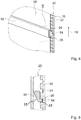
- FIG. 5 shows the carriage member 54 and the rail member 20 of the holding unit 16 in a sectional view along the sectional plane V in FIG. 4 ,
- the carriage member 54 has a latching lug 64 which engages in the latched positions 24, 26 of the latching means 22 in a locked state.
- the carriage member 54 may preferably include an insertion aid 65.
- the insertion aid 65 may be provided on the latching lug 64.
- the insertion aid 65 advantageously facilitates the engagement in a latching position 24, 26 or the unlatching / removal from a latching position 24, 26th
- FIG. 6 shows the holding unit 16 during a height adjustment of a holding element 18 of the holding unit 16 in a perspective view.
- the holding element 18 is mounted tiltably on the rail element 20.
- the holding element 18 can be tilted such that an upper side 66 of the holding element 18 is closer in a tilted state the shutter member 28 is located as a bottom 68 of the support member 18.
- the support member 18 can be adjusted in height.
- the carriage member 54 is moved up or down along the main extension direction of the rail member 20 in a vertical direction.
- the holding element 18 is guided movably guided along the rail element 20 by means of the fastening element 56 and the carriage element 54.
- a tilting of the retaining element 18 and a subsequent height adjustment of the retaining element 18 are possible without tools.
- FIG. 7 shows the carriage member 54 and the rail member 20 of the holding unit 16 during a height adjustment of the holding member 18 in a sectional view along the cutting plane V in FIG. 4 ,
- the carriage element 54 is tilted.
- the latching lug 56 is released from the corresponding latching position 26 of the latching means 22.
- the carriage member 54 is then movable along the rail member 20 and can be locked at any other locking position 26 again.
- the carriage member 54 may preferably have a contact surface 55 in one embodiment.
- the contact surface 55 preferably faces the diaphragm element 28.
- the contact surface 55 is arranged on a latching lug 64 opposite side of the carriage member 54.
- the contact surface 55 can be brought into contact with the diaphragm element 28 at a height adjustment.
- the panel member serves as a stop in this case, so that a user receives a hint when tilting that now a maximum tilting is achieved and a trouble-free height adjustment is possible.
- a latching takes place by tilting back of the retaining element 18, whereby a tilting back of the carriage member 54 takes place.
- the latching nose 56 engages in a latching position 24, 26 a.
- a tilting back of the retaining element 18 occurs due to a gravity of the retaining element 18, in particular automatically, in particular as soon as the operator releases the retaining element 18.
- FIG. 8 shows an exploded view of the holding unit 16, the shutter member 28 and a storage unit 38 of the household appliance device.
- the holding unit 16 has the two rail elements 20, 58.
- the rail elements 20, 58 each have a cover profile 70, 72, which at least partially cover the latching means 22, 74 of the rail elements 20, 58.
- the carriage elements 54, 60 of the holding unit 16 are integrally formed, each with a fastening element 56, 62 of the holding unit 16.
- the fastening elements 56, 62 can be inserted laterally into the retaining element 18.
- the hook profile 52 of the storage unit 38 is positively connected to the holding element 18 in an assembled state. Furthermore, the hook profile 52 of the storage unit 38 is positively connected to the diaphragm element 28 in an assembled state.
Landscapes
- Engineering & Computer Science (AREA)
- Chemical & Material Sciences (AREA)
- Combustion & Propulsion (AREA)
- Physics & Mathematics (AREA)
- Mechanical Engineering (AREA)
- Thermal Sciences (AREA)
- General Engineering & Computer Science (AREA)
- Drawers Of Furniture (AREA)
- Supports Or Holders For Household Use (AREA)
Applications Claiming Priority (1)
| Application Number | Priority Date | Filing Date | Title |
|---|---|---|---|
| DE102016202190.7A DE102016202190A1 (de) | 2016-02-12 | 2016-02-12 | Haushaltsgerätevorrichtung |
Publications (2)
| Publication Number | Publication Date |
|---|---|
| EP3205960A1 true EP3205960A1 (fr) | 2017-08-16 |
| EP3205960B1 EP3205960B1 (fr) | 2023-07-19 |
Family
ID=57882000
Family Applications (1)
| Application Number | Title | Priority Date | Filing Date |
|---|---|---|---|
| EP17152572.8A Active EP3205960B1 (fr) | 2016-02-12 | 2017-01-23 | Appareil frigorifique ménager et procédé pour le montage de l'appareil frigorifique ménager |
Country Status (4)
| Country | Link |
|---|---|
| US (1) | US20170234604A1 (fr) |
| EP (1) | EP3205960B1 (fr) |
| CN (1) | CN206891014U (fr) |
| DE (1) | DE102016202190A1 (fr) |
Families Citing this family (7)
| Publication number | Priority date | Publication date | Assignee | Title |
|---|---|---|---|---|
| DE102017001178A1 (de) * | 2016-11-08 | 2018-05-09 | Liebherr-Hausgeräte Lienz Gmbh | Kühl- und/oder Gefriergerät |
| DE102016013440A1 (de) * | 2016-11-10 | 2018-05-17 | Liebherr-Hausgeräte Lienz Gmbh | Kühl- und/oder Gefriergerät |
| US10827834B2 (en) * | 2018-10-22 | 2020-11-10 | Haier Us Appliance Solutions, Inc. | Bottle support assembly for a refrigerator appliance |
| DE102019114418A1 (de) * | 2019-04-18 | 2020-10-22 | Liebherr-Hausgeräte Lienz Gmbh | Kühl- und/oder Gefriergerät |
| CN113932543B (zh) * | 2020-07-13 | 2023-05-16 | 青岛海尔电冰箱有限公司 | 用于冰箱的搁架组件及冰箱 |
| DE102020211569A1 (de) | 2020-09-15 | 2022-03-17 | BSH Hausgeräte GmbH | Ablageplattenanordnung mit Trägerrahmen mit einer Profilschiene aus Metall, sowie Haushaltskältegerät |
| DE102020211570A1 (de) | 2020-09-15 | 2022-03-17 | BSH Hausgeräte GmbH | Einhängevorrichtung für einen Lebensmittel-Aufnahmebehälter mit einer Profilschiene aus Metall, Anordnung sowie Haushaltskältegerätbauteil |
Citations (10)
| Publication number | Priority date | Publication date | Assignee | Title |
|---|---|---|---|---|
| DE7247687U (de) * | 1972-01-10 | 1976-06-24 | Westinghouse Electric Corp., Pittsburgh, Pa. (V.St.A.) | Leitungskanal |
| EP0157461A2 (fr) * | 1984-04-05 | 1985-10-09 | Whirlpool International B.V. | Etagère amovible, en particulier pour un réfrigérateur |
| US5226707A (en) * | 1991-01-29 | 1993-07-13 | Samsung Electronics Co., Ltd. | Foodstuff container receiving apparatus |
| US5403083A (en) * | 1993-03-01 | 1995-04-04 | Whirlpool Corporation | Laterally adjustable cantilever shelf for a refrigerator |
| US5452812A (en) * | 1993-07-13 | 1995-09-26 | Sycamore Systems, Inc. | Shelving system |
| US6065821A (en) * | 1998-05-15 | 2000-05-23 | Maytag Corporation | Vertically adjustable shelf and support rail arrangement for use in a cabinet |
| DE69328470T2 (de) * | 1992-12-11 | 2000-09-14 | Gemtron Corp., Sweetwater | Einstellbares Regalsystem, insbesondere für Kühlschränke |
| JP2006230544A (ja) * | 2005-02-23 | 2006-09-07 | Senbi:Kk | 商品陳列台の商品支持具受け用部材 |
| DE102006061152A1 (de) * | 2006-12-22 | 2008-06-26 | BSH Bosch und Siemens Hausgeräte GmbH | Kältegerät |
| DE102011079197A1 (de) * | 2011-07-14 | 2013-01-17 | BSH Bosch und Siemens Hausgeräte GmbH | Haushaltskältegerät mit einer abnehmbar angeordneten Innenwandabdeckung |
Family Cites Families (5)
| Publication number | Priority date | Publication date | Assignee | Title |
|---|---|---|---|---|
| US5390802A (en) * | 1993-02-12 | 1995-02-21 | Hmg Worldwide In-Store Marketing, Inc. | Shelf assembly for gondola display structure |
| US5769520A (en) * | 1993-08-02 | 1998-06-23 | Goldstar Co., Ltd. | Shelf device for a refrigerator |
| US8608264B2 (en) * | 2006-04-28 | 2013-12-17 | Whirlpool Corporation | Refrigerator rail system for removably supported side-sliding shelves |
| US8182056B2 (en) * | 2007-09-05 | 2012-05-22 | Electrolux Home Products, Inc. | Offset weight supporting slide |
| US9261305B2 (en) * | 2013-03-07 | 2016-02-16 | Whirlpool Corporation | Shelving assembly for refrigerator compartment |
-
2016
- 2016-02-12 DE DE102016202190.7A patent/DE102016202190A1/de not_active Withdrawn
-
2017
- 2017-01-23 EP EP17152572.8A patent/EP3205960B1/fr active Active
- 2017-02-10 CN CN201720123517.9U patent/CN206891014U/zh not_active Expired - Fee Related
- 2017-02-13 US US15/430,717 patent/US20170234604A1/en not_active Abandoned
Patent Citations (10)
| Publication number | Priority date | Publication date | Assignee | Title |
|---|---|---|---|---|
| DE7247687U (de) * | 1972-01-10 | 1976-06-24 | Westinghouse Electric Corp., Pittsburgh, Pa. (V.St.A.) | Leitungskanal |
| EP0157461A2 (fr) * | 1984-04-05 | 1985-10-09 | Whirlpool International B.V. | Etagère amovible, en particulier pour un réfrigérateur |
| US5226707A (en) * | 1991-01-29 | 1993-07-13 | Samsung Electronics Co., Ltd. | Foodstuff container receiving apparatus |
| DE69328470T2 (de) * | 1992-12-11 | 2000-09-14 | Gemtron Corp., Sweetwater | Einstellbares Regalsystem, insbesondere für Kühlschränke |
| US5403083A (en) * | 1993-03-01 | 1995-04-04 | Whirlpool Corporation | Laterally adjustable cantilever shelf for a refrigerator |
| US5452812A (en) * | 1993-07-13 | 1995-09-26 | Sycamore Systems, Inc. | Shelving system |
| US6065821A (en) * | 1998-05-15 | 2000-05-23 | Maytag Corporation | Vertically adjustable shelf and support rail arrangement for use in a cabinet |
| JP2006230544A (ja) * | 2005-02-23 | 2006-09-07 | Senbi:Kk | 商品陳列台の商品支持具受け用部材 |
| DE102006061152A1 (de) * | 2006-12-22 | 2008-06-26 | BSH Bosch und Siemens Hausgeräte GmbH | Kältegerät |
| DE102011079197A1 (de) * | 2011-07-14 | 2013-01-17 | BSH Bosch und Siemens Hausgeräte GmbH | Haushaltskältegerät mit einer abnehmbar angeordneten Innenwandabdeckung |
Also Published As
| Publication number | Publication date |
|---|---|
| EP3205960B1 (fr) | 2023-07-19 |
| US20170234604A1 (en) | 2017-08-17 |
| DE102016202190A1 (de) | 2017-08-17 |
| CN206891014U (zh) | 2018-01-16 |
Similar Documents
| Publication | Publication Date | Title |
|---|---|---|
| EP3205960B1 (fr) | Appareil frigorifique ménager et procédé pour le montage de l'appareil frigorifique ménager | |
| DE10216769A1 (de) | Konsole für Tragböden in Haushaltsgeräten | |
| DE10051153A1 (de) | Gargutträgersystem für einen Backofen | |
| DE102009046612A1 (de) | Kältegerät mit einem Türabsteller und einer schwimmend gelagerten Rastvorrichtung | |
| EP2276986B1 (fr) | Appareil frigorifique | |
| DE102017205108A1 (de) | Haushaltskältegerätevorrichtung | |
| EP3205961A1 (fr) | Dispositif d'appareil ménager | |
| WO2017137239A1 (fr) | Appareil ménager | |
| EP3199896B1 (fr) | Étagère de réfrigérateur dotée d'un élément ressort | |
| WO2017137240A1 (fr) | Appareil ménager | |
| DE102015005666A1 (de) | Türanordnung für Kühlvitrine | |
| DE102009054661A1 (de) | Kältegerät mit einem Türabsteller und einer Rastvorrichtung | |
| DE102009046613A1 (de) | Kältegerät mit einem Türabsteller und einer Rastvorrichtung | |
| EP0424694B1 (fr) | Appareil de réfrigération ou de congélation avec une plaque de rayonnage en verre | |
| DE102012001374B4 (de) | Kühl- und/oder Gefriergerät | |
| CH683680A5 (de) | Tablar zum Einbau in den Innenraum von Kühlschränken. | |
| DE19916621C2 (de) | Kühlgerät mit Tragboden | |
| EP2618084B1 (fr) | Dispositif de dépôt avec un dispositif de fixation de clapet et appareil ménager réfrigérant avec un tel dispositif de dépôt | |
| EP2585776B1 (fr) | Appareil de froid domestique | |
| DE102015012638A1 (de) | Türanordnung und Kühlmöbel | |
| EP2156122B1 (fr) | Fond de rayonnage pour un appareil frigorifique | |
| DE102016202189A1 (de) | Haushaltgerätevorrichtung | |
| DE202015003240U1 (de) | Türanordnung für Kühlvitrine | |
| DE19527731A1 (de) | Kühlschrank | |
| WO2009124864A2 (fr) | Appareil frigorifique doté de compartiments de porte |
Legal Events
| Date | Code | Title | Description |
|---|---|---|---|
| PUAI | Public reference made under article 153(3) epc to a published international application that has entered the european phase |
Free format text: ORIGINAL CODE: 0009012 |
|
| STAA | Information on the status of an ep patent application or granted ep patent |
Free format text: STATUS: THE APPLICATION HAS BEEN PUBLISHED |
|
| AK | Designated contracting states |
Kind code of ref document: A1 Designated state(s): AL AT BE BG CH CY CZ DE DK EE ES FI FR GB GR HR HU IE IS IT LI LT LU LV MC MK MT NL NO PL PT RO RS SE SI SK SM TR |
|
| AX | Request for extension of the european patent |
Extension state: BA ME |
|
| STAA | Information on the status of an ep patent application or granted ep patent |
Free format text: STATUS: REQUEST FOR EXAMINATION WAS MADE |
|
| 17P | Request for examination filed |
Effective date: 20180216 |
|
| RBV | Designated contracting states (corrected) |
Designated state(s): AL AT BE BG CH CY CZ DE DK EE ES FI FR GB GR HR HU IE IS IT LI LT LU LV MC MK MT NL NO PL PT RO RS SE SI SK SM TR |
|
| STAA | Information on the status of an ep patent application or granted ep patent |
Free format text: STATUS: EXAMINATION IS IN PROGRESS |
|
| 17Q | First examination report despatched |
Effective date: 20190719 |
|
| GRAP | Despatch of communication of intention to grant a patent |
Free format text: ORIGINAL CODE: EPIDOSNIGR1 |
|
| STAA | Information on the status of an ep patent application or granted ep patent |
Free format text: STATUS: GRANT OF PATENT IS INTENDED |
|
| INTG | Intention to grant announced |
Effective date: 20230307 |
|
| GRAS | Grant fee paid |
Free format text: ORIGINAL CODE: EPIDOSNIGR3 |
|
| GRAA | (expected) grant |
Free format text: ORIGINAL CODE: 0009210 |
|
| STAA | Information on the status of an ep patent application or granted ep patent |
Free format text: STATUS: THE PATENT HAS BEEN GRANTED |
|
| AK | Designated contracting states |
Kind code of ref document: B1 Designated state(s): AL AT BE BG CH CY CZ DE DK EE ES FI FR GB GR HR HU IE IS IT LI LT LU LV MC MK MT NL NO PL PT RO RS SE SI SK SM TR |
|
| REG | Reference to a national code |
Ref country code: GB Ref legal event code: FG4D Free format text: NOT ENGLISH |
|
| REG | Reference to a national code |
Ref country code: CH Ref legal event code: EP |
|
| REG | Reference to a national code |
Ref country code: DE Ref legal event code: R096 Ref document number: 502017015066 Country of ref document: DE |
|
| P01 | Opt-out of the competence of the unified patent court (upc) registered |
Effective date: 20230707 |
|
| REG | Reference to a national code |
Ref country code: IE Ref legal event code: FG4D Free format text: LANGUAGE OF EP DOCUMENT: GERMAN |
|
| REG | Reference to a national code |
Ref country code: LT Ref legal event code: MG9D |
|
| REG | Reference to a national code |
Ref country code: NL Ref legal event code: MP Effective date: 20230719 |
|
| PG25 | Lapsed in a contracting state [announced via postgrant information from national office to epo] |
Ref country code: NL Free format text: LAPSE BECAUSE OF FAILURE TO SUBMIT A TRANSLATION OF THE DESCRIPTION OR TO PAY THE FEE WITHIN THE PRESCRIBED TIME-LIMIT Effective date: 20230719 |
|
| PG25 | Lapsed in a contracting state [announced via postgrant information from national office to epo] |
Ref country code: GR Free format text: LAPSE BECAUSE OF FAILURE TO SUBMIT A TRANSLATION OF THE DESCRIPTION OR TO PAY THE FEE WITHIN THE PRESCRIBED TIME-LIMIT Effective date: 20231020 |
|
| PG25 | Lapsed in a contracting state [announced via postgrant information from national office to epo] |
Ref country code: IS Free format text: LAPSE BECAUSE OF FAILURE TO SUBMIT A TRANSLATION OF THE DESCRIPTION OR TO PAY THE FEE WITHIN THE PRESCRIBED TIME-LIMIT Effective date: 20231119 |
|
| PG25 | Lapsed in a contracting state [announced via postgrant information from national office to epo] |
Ref country code: SE Free format text: LAPSE BECAUSE OF FAILURE TO SUBMIT A TRANSLATION OF THE DESCRIPTION OR TO PAY THE FEE WITHIN THE PRESCRIBED TIME-LIMIT Effective date: 20230719 Ref country code: RS Free format text: LAPSE BECAUSE OF FAILURE TO SUBMIT A TRANSLATION OF THE DESCRIPTION OR TO PAY THE FEE WITHIN THE PRESCRIBED TIME-LIMIT Effective date: 20230719 Ref country code: PT Free format text: LAPSE BECAUSE OF FAILURE TO SUBMIT A TRANSLATION OF THE DESCRIPTION OR TO PAY THE FEE WITHIN THE PRESCRIBED TIME-LIMIT Effective date: 20231120 Ref country code: NO Free format text: LAPSE BECAUSE OF FAILURE TO SUBMIT A TRANSLATION OF THE DESCRIPTION OR TO PAY THE FEE WITHIN THE PRESCRIBED TIME-LIMIT Effective date: 20231019 Ref country code: LV Free format text: LAPSE BECAUSE OF FAILURE TO SUBMIT A TRANSLATION OF THE DESCRIPTION OR TO PAY THE FEE WITHIN THE PRESCRIBED TIME-LIMIT Effective date: 20230719 Ref country code: LT Free format text: LAPSE BECAUSE OF FAILURE TO SUBMIT A TRANSLATION OF THE DESCRIPTION OR TO PAY THE FEE WITHIN THE PRESCRIBED TIME-LIMIT Effective date: 20230719 Ref country code: IS Free format text: LAPSE BECAUSE OF FAILURE TO SUBMIT A TRANSLATION OF THE DESCRIPTION OR TO PAY THE FEE WITHIN THE PRESCRIBED TIME-LIMIT Effective date: 20231119 Ref country code: HR Free format text: LAPSE BECAUSE OF FAILURE TO SUBMIT A TRANSLATION OF THE DESCRIPTION OR TO PAY THE FEE WITHIN THE PRESCRIBED TIME-LIMIT Effective date: 20230719 Ref country code: GR Free format text: LAPSE BECAUSE OF FAILURE TO SUBMIT A TRANSLATION OF THE DESCRIPTION OR TO PAY THE FEE WITHIN THE PRESCRIBED TIME-LIMIT Effective date: 20231020 Ref country code: FI Free format text: LAPSE BECAUSE OF FAILURE TO SUBMIT A TRANSLATION OF THE DESCRIPTION OR TO PAY THE FEE WITHIN THE PRESCRIBED TIME-LIMIT Effective date: 20230719 |
|
| PG25 | Lapsed in a contracting state [announced via postgrant information from national office to epo] |
Ref country code: PL Free format text: LAPSE BECAUSE OF FAILURE TO SUBMIT A TRANSLATION OF THE DESCRIPTION OR TO PAY THE FEE WITHIN THE PRESCRIBED TIME-LIMIT Effective date: 20230719 |
|
| REG | Reference to a national code |
Ref country code: DE Ref legal event code: R097 Ref document number: 502017015066 Country of ref document: DE |
|
| PG25 | Lapsed in a contracting state [announced via postgrant information from national office to epo] |
Ref country code: ES Free format text: LAPSE BECAUSE OF FAILURE TO SUBMIT A TRANSLATION OF THE DESCRIPTION OR TO PAY THE FEE WITHIN THE PRESCRIBED TIME-LIMIT Effective date: 20230719 |
|
| PG25 | Lapsed in a contracting state [announced via postgrant information from national office to epo] |
Ref country code: SM Free format text: LAPSE BECAUSE OF FAILURE TO SUBMIT A TRANSLATION OF THE DESCRIPTION OR TO PAY THE FEE WITHIN THE PRESCRIBED TIME-LIMIT Effective date: 20230719 Ref country code: RO Free format text: LAPSE BECAUSE OF FAILURE TO SUBMIT A TRANSLATION OF THE DESCRIPTION OR TO PAY THE FEE WITHIN THE PRESCRIBED TIME-LIMIT Effective date: 20230719 Ref country code: ES Free format text: LAPSE BECAUSE OF FAILURE TO SUBMIT A TRANSLATION OF THE DESCRIPTION OR TO PAY THE FEE WITHIN THE PRESCRIBED TIME-LIMIT Effective date: 20230719 Ref country code: EE Free format text: LAPSE BECAUSE OF FAILURE TO SUBMIT A TRANSLATION OF THE DESCRIPTION OR TO PAY THE FEE WITHIN THE PRESCRIBED TIME-LIMIT Effective date: 20230719 Ref country code: DK Free format text: LAPSE BECAUSE OF FAILURE TO SUBMIT A TRANSLATION OF THE DESCRIPTION OR TO PAY THE FEE WITHIN THE PRESCRIBED TIME-LIMIT Effective date: 20230719 Ref country code: CZ Free format text: LAPSE BECAUSE OF FAILURE TO SUBMIT A TRANSLATION OF THE DESCRIPTION OR TO PAY THE FEE WITHIN THE PRESCRIBED TIME-LIMIT Effective date: 20230719 Ref country code: SK Free format text: LAPSE BECAUSE OF FAILURE TO SUBMIT A TRANSLATION OF THE DESCRIPTION OR TO PAY THE FEE WITHIN THE PRESCRIBED TIME-LIMIT Effective date: 20230719 |
|
| PLBE | No opposition filed within time limit |
Free format text: ORIGINAL CODE: 0009261 |
|
| STAA | Information on the status of an ep patent application or granted ep patent |
Free format text: STATUS: NO OPPOSITION FILED WITHIN TIME LIMIT |
|
| PG25 | Lapsed in a contracting state [announced via postgrant information from national office to epo] |
Ref country code: IT Free format text: LAPSE BECAUSE OF FAILURE TO SUBMIT A TRANSLATION OF THE DESCRIPTION OR TO PAY THE FEE WITHIN THE PRESCRIBED TIME-LIMIT Effective date: 20230719 |
|
| 26N | No opposition filed |
Effective date: 20240422 |
|
| PG25 | Lapsed in a contracting state [announced via postgrant information from national office to epo] |
Ref country code: SI Free format text: LAPSE BECAUSE OF FAILURE TO SUBMIT A TRANSLATION OF THE DESCRIPTION OR TO PAY THE FEE WITHIN THE PRESCRIBED TIME-LIMIT Effective date: 20230719 |
|
| REG | Reference to a national code |
Ref country code: DE Ref legal event code: R119 Ref document number: 502017015066 Country of ref document: DE |
|
| PG25 | Lapsed in a contracting state [announced via postgrant information from national office to epo] |
Ref country code: MC Free format text: LAPSE BECAUSE OF FAILURE TO SUBMIT A TRANSLATION OF THE DESCRIPTION OR TO PAY THE FEE WITHIN THE PRESCRIBED TIME-LIMIT Effective date: 20230719 |
|
| PG25 | Lapsed in a contracting state [announced via postgrant information from national office to epo] |
Ref country code: MC Free format text: LAPSE BECAUSE OF FAILURE TO SUBMIT A TRANSLATION OF THE DESCRIPTION OR TO PAY THE FEE WITHIN THE PRESCRIBED TIME-LIMIT Effective date: 20230719 |
|
| REG | Reference to a national code |
Ref country code: CH Ref legal event code: PL |
|
| PG25 | Lapsed in a contracting state [announced via postgrant information from national office to epo] |
Ref country code: LU Free format text: LAPSE BECAUSE OF NON-PAYMENT OF DUE FEES Effective date: 20240123 |
|
| GBPC | Gb: european patent ceased through non-payment of renewal fee |
Effective date: 20240123 |
|
| PG25 | Lapsed in a contracting state [announced via postgrant information from national office to epo] |
Ref country code: LU Free format text: LAPSE BECAUSE OF NON-PAYMENT OF DUE FEES Effective date: 20240123 |
|
| PG25 | Lapsed in a contracting state [announced via postgrant information from national office to epo] |
Ref country code: DE Free format text: LAPSE BECAUSE OF NON-PAYMENT OF DUE FEES Effective date: 20240801 |
|
| PG25 | Lapsed in a contracting state [announced via postgrant information from national office to epo] |
Ref country code: GB Free format text: LAPSE BECAUSE OF NON-PAYMENT OF DUE FEES Effective date: 20240123 |
|
| PG25 | Lapsed in a contracting state [announced via postgrant information from national office to epo] |
Ref country code: BE Free format text: LAPSE BECAUSE OF NON-PAYMENT OF DUE FEES Effective date: 20240131 |
|
| PG25 | Lapsed in a contracting state [announced via postgrant information from national office to epo] |
Ref country code: FR Free format text: LAPSE BECAUSE OF NON-PAYMENT OF DUE FEES Effective date: 20240131 |
|
| PG25 | Lapsed in a contracting state [announced via postgrant information from national office to epo] |
Ref country code: CH Free format text: LAPSE BECAUSE OF NON-PAYMENT OF DUE FEES Effective date: 20240131 |
|
| PG25 | Lapsed in a contracting state [announced via postgrant information from national office to epo] |
Ref country code: GB Free format text: LAPSE BECAUSE OF NON-PAYMENT OF DUE FEES Effective date: 20240123 Ref country code: FR Free format text: LAPSE BECAUSE OF NON-PAYMENT OF DUE FEES Effective date: 20240131 Ref country code: DE Free format text: LAPSE BECAUSE OF NON-PAYMENT OF DUE FEES Effective date: 20240801 Ref country code: CH Free format text: LAPSE BECAUSE OF NON-PAYMENT OF DUE FEES Effective date: 20240131 Ref country code: BE Free format text: LAPSE BECAUSE OF NON-PAYMENT OF DUE FEES Effective date: 20240131 |
|
| REG | Reference to a national code |
Ref country code: BE Ref legal event code: MM Effective date: 20240131 |
|
| PG25 | Lapsed in a contracting state [announced via postgrant information from national office to epo] |
Ref country code: BG Free format text: LAPSE BECAUSE OF FAILURE TO SUBMIT A TRANSLATION OF THE DESCRIPTION OR TO PAY THE FEE WITHIN THE PRESCRIBED TIME-LIMIT Effective date: 20230719 |
|
| PG25 | Lapsed in a contracting state [announced via postgrant information from national office to epo] |
Ref country code: BG Free format text: LAPSE BECAUSE OF FAILURE TO SUBMIT A TRANSLATION OF THE DESCRIPTION OR TO PAY THE FEE WITHIN THE PRESCRIBED TIME-LIMIT Effective date: 20230719 |
|
| PG25 | Lapsed in a contracting state [announced via postgrant information from national office to epo] |
Ref country code: IE Free format text: LAPSE BECAUSE OF NON-PAYMENT OF DUE FEES Effective date: 20240123 |
|
| PG25 | Lapsed in a contracting state [announced via postgrant information from national office to epo] |
Ref country code: IE Free format text: LAPSE BECAUSE OF NON-PAYMENT OF DUE FEES Effective date: 20240123 |
|
| REG | Reference to a national code |
Ref country code: AT Ref legal event code: MM01 Ref document number: 1589844 Country of ref document: AT Kind code of ref document: T Effective date: 20240123 |
|
| PG25 | Lapsed in a contracting state [announced via postgrant information from national office to epo] |
Ref country code: AT Free format text: LAPSE BECAUSE OF NON-PAYMENT OF DUE FEES Effective date: 20240123 |
|
| PG25 | Lapsed in a contracting state [announced via postgrant information from national office to epo] |
Ref country code: CY Free format text: LAPSE BECAUSE OF FAILURE TO SUBMIT A TRANSLATION OF THE DESCRIPTION OR TO PAY THE FEE WITHIN THE PRESCRIBED TIME-LIMIT; INVALID AB INITIO Effective date: 20170123 |
|
| PG25 | Lapsed in a contracting state [announced via postgrant information from national office to epo] |
Ref country code: HU Free format text: LAPSE BECAUSE OF FAILURE TO SUBMIT A TRANSLATION OF THE DESCRIPTION OR TO PAY THE FEE WITHIN THE PRESCRIBED TIME-LIMIT; INVALID AB INITIO Effective date: 20170123 |
|
| PG25 | Lapsed in a contracting state [announced via postgrant information from national office to epo] |
Ref country code: TR Free format text: LAPSE BECAUSE OF FAILURE TO SUBMIT A TRANSLATION OF THE DESCRIPTION OR TO PAY THE FEE WITHIN THE PRESCRIBED TIME-LIMIT Effective date: 20230719 |