EP3206003B1 - Système et dispositif de détection d'anomalie de machines tournantes - Google Patents
Système et dispositif de détection d'anomalie de machines tournantes Download PDFInfo
- Publication number
- EP3206003B1 EP3206003B1 EP16207234.2A EP16207234A EP3206003B1 EP 3206003 B1 EP3206003 B1 EP 3206003B1 EP 16207234 A EP16207234 A EP 16207234A EP 3206003 B1 EP3206003 B1 EP 3206003B1
- Authority
- EP
- European Patent Office
- Prior art keywords
- abnormality
- detecting
- rotating machines
- frequency
- frequency analysis
- Prior art date
- Legal status (The legal status is an assumption and is not a legal conclusion. Google has not performed a legal analysis and makes no representation as to the accuracy of the status listed.)
- Active
Links
Images



Classifications
-
- G—PHYSICS
- G01—MEASURING; TESTING
- G01H—MEASUREMENT OF MECHANICAL VIBRATIONS OR ULTRASONIC, SONIC OR INFRASONIC WAVES
- G01H1/00—Measuring characteristics of vibrations in solids by using direct conduction to the detector
- G01H1/003—Measuring characteristics of vibrations in solids by using direct conduction to the detector of rotating machines
-
- G—PHYSICS
- G01—MEASURING; TESTING
- G01N—INVESTIGATING OR ANALYSING MATERIALS BY DETERMINING THEIR CHEMICAL OR PHYSICAL PROPERTIES
- G01N29/00—Investigating or analysing materials by the use of ultrasonic, sonic or infrasonic waves; Visualisation of the interior of objects by transmitting ultrasonic or sonic waves through the object
- G01N29/44—Processing the detected response signal, e.g. electronic circuits specially adapted therefor
- G01N29/46—Processing the detected response signal, e.g. electronic circuits specially adapted therefor by spectral analysis, e.g. Fourier analysis or wavelet analysis
-
- F—MECHANICAL ENGINEERING; LIGHTING; HEATING; WEAPONS; BLASTING
- F01—MACHINES OR ENGINES IN GENERAL; ENGINE PLANTS IN GENERAL; STEAM ENGINES
- F01D—NON-POSITIVE DISPLACEMENT MACHINES OR ENGINES, e.g. STEAM TURBINES
- F01D21/00—Shutting-down of machines or engines, e.g. in emergency; Regulating, controlling, or safety means not otherwise provided for
- F01D21/003—Arrangements for testing or measuring
-
- F—MECHANICAL ENGINEERING; LIGHTING; HEATING; WEAPONS; BLASTING
- F04—POSITIVE - DISPLACEMENT MACHINES FOR LIQUIDS; PUMPS FOR LIQUIDS OR ELASTIC FLUIDS
- F04D—NON-POSITIVE-DISPLACEMENT PUMPS
- F04D27/00—Control, e.g. regulation, of pumps, pumping installations or pumping systems specially adapted for elastic fluids
- F04D27/001—Testing thereof; Determination or simulation of flow characteristics; Stall or surge detection, e.g. condition monitoring
-
- G—PHYSICS
- G01—MEASURING; TESTING
- G01H—MEASUREMENT OF MECHANICAL VIBRATIONS OR ULTRASONIC, SONIC OR INFRASONIC WAVES
- G01H1/00—Measuring characteristics of vibrations in solids by using direct conduction to the detector
- G01H1/003—Measuring characteristics of vibrations in solids by using direct conduction to the detector of rotating machines
- G01H1/006—Measuring characteristics of vibrations in solids by using direct conduction to the detector of rotating machines of the rotor of turbo machines
-
- G—PHYSICS
- G01—MEASURING; TESTING
- G01M—TESTING STATIC OR DYNAMIC BALANCE OF MACHINES OR STRUCTURES; TESTING OF STRUCTURES OR APPARATUS, NOT OTHERWISE PROVIDED FOR
- G01M15/00—Testing of engines
- G01M15/14—Testing gas-turbine engines or jet-propulsion engines
-
- G—PHYSICS
- G01—MEASURING; TESTING
- G01M—TESTING STATIC OR DYNAMIC BALANCE OF MACHINES OR STRUCTURES; TESTING OF STRUCTURES OR APPARATUS, NOT OTHERWISE PROVIDED FOR
- G01M5/00—Investigating the elasticity of structures, e.g. deflection of bridges or air-craft wings
- G01M5/0016—Investigating the elasticity of structures, e.g. deflection of bridges or air-craft wings of aircraft wings or blades
-
- G—PHYSICS
- G01—MEASURING; TESTING
- G01N—INVESTIGATING OR ANALYSING MATERIALS BY DETERMINING THEIR CHEMICAL OR PHYSICAL PROPERTIES
- G01N29/00—Investigating or analysing materials by the use of ultrasonic, sonic or infrasonic waves; Visualisation of the interior of objects by transmitting ultrasonic or sonic waves through the object
- G01N29/14—Investigating or analysing materials by the use of ultrasonic, sonic or infrasonic waves; Visualisation of the interior of objects by transmitting ultrasonic or sonic waves through the object using acoustic emission techniques
-
- G—PHYSICS
- G01—MEASURING; TESTING
- G01N—INVESTIGATING OR ANALYSING MATERIALS BY DETERMINING THEIR CHEMICAL OR PHYSICAL PROPERTIES
- G01N29/00—Investigating or analysing materials by the use of ultrasonic, sonic or infrasonic waves; Visualisation of the interior of objects by transmitting ultrasonic or sonic waves through the object
- G01N29/44—Processing the detected response signal, e.g. electronic circuits specially adapted therefor
- G01N29/4409—Processing the detected response signal, e.g. electronic circuits specially adapted therefor by comparison
- G01N29/4427—Processing the detected response signal, e.g. electronic circuits specially adapted therefor by comparison with stored values, e.g. threshold values
Definitions
- the present invention relates to a system and a method for suitably detecting an abnormality of a rotating machine such as, for example, an abnormality of a rotor.
- rotors During the operation of rotating machines such as turbines and compressors, rotors usually rotate at high speed. Later detection of an abnormality such as damage of the rotors, for example, may lead to increased severity of the abnormality. To make matters worse, the abnormality may result in shutdown of the rotating machines. Thus, it is desirable to early detect and notify such abnormality of rotating machines.
- a device for diagnosing abnormal slide uses an AE (acoustic emission) sensor to detect an AE signal from a rotating machine; analyzes the frequency of the detected AE signal to determine the presence, location, and degree of abnormal slide; and displays the result of the determination.
- AE acoustic emission
- Document WO 2013 009 258 A1 discloses a method and system for analyzing the condition of a rotating machine part comprising the steps of receiving a first digital signal dependent on mechanical vibrations emanating from rotation of the part, and analyzing the first digital signal so as to detect peak amplitude values during a finite time period.
- Document US 5 965 819 A discloses a hand held data collector and analyzer for collecting, analyzing and storing data relating to the operational characteristics of a machine.
- a vibration transducer in the sensor senses the vibrations produced by the machine and then, first and second digital signals are produced.
- the first and second digital signals are respectively received by first and second data processors that process the digital signals to produce a set of desired digital data.
- This frequency spectrum can be examined to determine the absence or presence of machine defects.
- Document JP S63 150 633 A discloses a method and system for analyzing the condition of a rotating machine part comprising the steps of receiving a first digital signal dependent on mechanical vibrations emanating from rotation of the part, and analyzing the first digital signal so as to detect peak amplitude values during a finite time period.
- JP 8-166330 displays the results of determination of the presence, location, and degree of abnormal slide, the device does not display trends in the results over time. Thus, the conventional device can identify, for example, the presence of an abnormality of a rotating machine but is difficult to early detect the abnormality
- the present invention has been developed in view of the foregoing. It is an object of the present invention to provide a system and a method for detecting an abnormality of a rotating machine, the system and the method being able to early detect an abnormality of a rotating machine
- a first aspect of the present invention is a system for detecting an abnormality of rotating machines, the system including two or more devices for detecting an abnormality and a computer, wherein the two or more devices detect an abnormality of two or more rotating machines to which the devices are allocated respectively, wherein the two or more devices individually include a sensor for detecting vibration of rotating machines to which the devices are allocated and generating a signal indicative of the detected vibration and a transmitting unit for transmitting, to the computer, the signal generated by the sensor, and wherein the computer includes a sampler for sampling and detecting, with a predetermined sampling frequency, the signal that is transmitted by the transmitting units of the respective two or more devices and that are indicative of the vibration and outputting, at a time at intervals of a predetermined period, a plurality of the sampled data detected within the predetermined period, a storage for storing the plurality of the sampled data that are outputted by the sampler and that correspond to the respective two or more rotating machines, a frequency analyzer for analyzing frequencies of the plurality of the sampled
- the sampler outputs, at a time at intervals of a predetermined period, a plurality of the sampled data detected within the predetermined period.
- the sampler may output, at a time at intervals of a predetermined period, all of a plurality of the sampled data detected within the predetermined period or may output, at a time, part of the plurality of the sampled data.
- the system for detecting an abnormality of rotating machines displays, in chronological order and in real time, the results of frequency analysis of the sampled data created by sampling and detecting vibration of the rotating machines.
- the system displays, substantially in real time, the operating states of the rotating machines at respective times, which allows an operator to recognize a change in operation states of the rotating machines over time.
- the system for detecting an abnormality of rotating machines according to the first aspect of the present invention can early detect an abnormality of the rotating machines.
- the system for detecting an abnormality of rotating machines according to the first aspect of the present invention displays, on the single display unit, the results of the frequency analysis and the results of the abnormality determination for the respective two or more rotating machines, which allows collective control of detection of an abnormality of tho respective two or more rotating machines.
- the system for detecting an abnormality of rotating machines according to the first aspect of the present invention allows a reduction in the number of people who manage the process of detecting an abnormality of two or more rotating machines.
- the frequency analyzer preferably analyzes frequencies of the plurality of the sampled data by fast Fourier transform and outputs amplitude data corresponding to the respective frequencies.
- the display unit displays the results of the frequency analysis in two dimensions: the frequency dimension and the amplitude dimension.
- the display unit displays the results of the frequency analysis at respective times in chronological order, in three dimensions, and in real time.
- the display unit displays the results of the frequency analysis of the sampled data in chronological order, in real time, and in three dimensions: the frequency dimension, the amplitude dimension (the amplitude dimension indicating amplitudes corresponding to respective frequencies), and time dimension, which allows an operator to readily visually recognize a change in operation states of the rotating machines over time.
- the frequency analyzer initiates the frequency analysis when the frequency analyzer has received the plurality of the sampled data from the detecting unit.
- the analysis period from the initiation of the frequency analysis to the end of the frequency analysis is shorter than the predetermined period described above.
- the frequency analyzer can complete, within the predetermined period, the frequency analysis of all of the plurality of the sampled data received at the beginning of the predetermined period.
- the storage initiates storage of the plurality of the sampled data and the results of the frequency analysis when the storage has received the plurality of the sampled data from the detecting unit.
- the storage period from the initiation of storage of the plurality of the sampled data to the end of the storage is shorter than the predetermined period.
- the storage can initiate storage of the plurality of the sampled data and the results of the frequency analysis when the storage has received the data.
- the system for detecting an abnormality of rotating machines can store, to the storage within the predetermined period, all of the plurality of the sampled data received at the beginning of the predetermined period.
- the system for detecting an abnormality of rotating machines further includes a termination instruction input unit for receiving an instruction to terminate detection of the abnormality.
- the frequency analyzer preferably reads all of the plurality of the sampled data stored in the storage, performs the frequency analysis, and stores the results of the frequency analysis in chronological order in the storage.
- the frequency analyzer stores the results of the frequency analysis in chronological order in the storage upon terminating detection of the abnormality, which can reduce the processing load for the storage process, for example via a controller, compared with a case in which the results of the frequency analysis are stored during the frequency analysis.
- the frequency analyzer is functionally configured in a processor by executing a predetermined frequency-analysis-program.
- the frequency analyzer is functionally configured in the processor upon initiating the frequency analysis, while the frequency analyzer is cleared from the processor upon terminating the frequency analysis.
- a plurality of frequency analyzers can be functionally configured in parallel. As the frequency analyzers are configured when necessary, the system for detecting an abnormality of rotating machines only needs to control the frequency analyzers that are functionally configured in the processor when necessary, which can reduce the processing load of the processor, compared with a case in which a predetermined number of frequency analyzers are functionally pro-configured.
- a second aspect of the present invention is a method for detecting an abnormality of two or more rotating machines according to claim 8.
- the second aspect of the present invention has the same effects as the first aspect of the present invention.
- the present invention allows early detection of an abnormality of a rotating machine.
- FIG. 1 is a block diagram illustrating an exemplary configuration of a system 100 for detecting an abnormality of rotating machines (hereinafter also simply referred to as "system for detecting an abnormality") according to an embodiment of the present invention.
- the system 100 for detecting an abnormality controls an abnormality of respective n rotating machines 5-1 to 5-n by a single computer 8, wherein n is an integer of two or more.
- the rotating machines 5-1 to 5-n may be collectively referred to as "rotating machines 5".
- the n rotating machines 5 may be disposed in a single line, or each of the n rotating machines 5 may be disposed in each of n lines.
- the system 100 for detecting an abnormality includes, for example, n detecting units 1-1 to 1-n, an arithmetic processing unit 2, a display unit 3, and an input unit 4.
- the detecting units 1-1 to 1-n may be collectively referred to as "detecting units 1".
- the detecting units 1 are connected to the arithmetic processing unit 2, which is connected to the display unit 3.
- the input unit 4 is connected to the arithmetic processing unit 2.
- the computer 8 is constituted by the arithmetic processing unit 2, a sampler 12, the display unit 3, and the input unit 4.
- a computer unit 9 is constituted by the arithmetic processing unit 2 and the sampler 12.
- the respective detecting units 1-1 to 1-n are allocated to the respective n rotating machines 5-1 to 5-n.
- the detecting unit 1-1 is used to detect an abnormality of the rotating machine 5-1
- the detecting unit 1-2 is used to detect an abnormality of the rotating machine 5-2
- the detecting unit 1-n is used to detect an abnormality of the rotating machine 5-n.
- the detecting units 1-1 to 1-n have the same configuration.
- the detecting units 1-1 to 1-n share the sampler 12.
- the system 100 for detecting an abnormality of rotating machines includes a lot of the detecting units 1
- the system 100 includes a plurality of the samplers 12, and the n detecting units 1-1 to 1-n are divided into a plurality of groups.
- the detecting units 1 in each of the groups may be allocated to one of the samplers 12. This allows prevention of latency in processing by the samplers 12 even when the system 100 includes a lot of the detecting units 1.
- the detecting units 1 sample and detect vibration of the rotating machines 5 to be inspected with a predetermined sampling frequency, and outputs, to the arithmetic processing unit 2 at a time at intervals of a predetermined period, all of a plurality of the sampled data detected within the predetermined period.
- the detecting units 1 include, for example, sensors 10 (10a to 10d), amplifiers 11 (11a and 11b), a transmitting unit 6, and the sampler 12.
- the sensors 10 are connected to the amplifiers 11, which are connected to the transmitting unit 6.
- the transmitting unit 6 is connected to the sampler 12, which is connected to the arithmetic processing unit 2.
- the sensors 10 detect vibration of the rotating machines 5 to be inspected.
- the sensors 10 are an electro-mechanical energy converting element that contains a material such as piezoceramics and that converts vibrational mechanical energy to electrical energy.
- the sensors 10 are, for example, AE (acoustic emission) sensors, acceleration sensors or the like.
- One or more sensors 10 may be used.
- two AE sensors 10a and 10b and two acceleration sensors 10c and 10d are used.
- the AE sensors 10a and 10b and the acceleration sensors 10c and 10d are attached to the body of the rotating machines 5 such as turbines and compressors.
- the AE sensors 10a and 10b detect an abnormality, such as, contact between two rotors that are usually spaced from each other, by detecting AE waves due to the abnormality.
- the acceleration sensors 10c and 10d detect the vibration acceleration of the rotating machines 5due to the abnormality.
- the amplifiers 11 amplify each small detected signal outputted by the sensors 10.
- the number of the amplifiers 11 depends on the number of the sensors 10. In the embodiment, two amplifiers 11a and 11b are used.
- the amplifier 11a is connected to the AE sensors 10a and 10b.
- the amplifier 11b is connected to the acceleration sensors 10c and 10d.
- the amplifier 11a individually amplifies each signal outputted by the AE sensors 10a and 10b and individually outputs each amplified signal.
- the amplifier 11b individually amplifies each signal outputted by the acceleration sensors 10c and 10d and individually outputs each amplified signal.
- the transmitting unit 6 transmits, to the sampler 12, the signals amplified by the amplifiers 11a and 11b.
- the sampler 12 samples the vibration of the rotating machines 5 with a predetermined sampling frequency and outputs all of the plurality of the sampled data to the arithmetic processing unit 2. All of the plurality of the sampled data are outputted at a time by the sampler 12, as instructed by the arithmetic processing unit 2.
- the sampler 12 which includes, for example, a register 12a, individually samples respective signals that are, for example, detected by the AE sensors 10a and 10b and that are individually outputted by the amplifier 11a with a sampling frequency of 1 MHz at the same timing; A/D-converts the signals; and stores the signals in the register 12a.
- the sampler samples respective signals that are detected by the acceleration sensors 10c and 10d and individually outputted by the amplifier 11b with a sampling frequency of 20 kHz at the same timing; A/D-converts the signals; and stores the signals in the register 12a. Therefore, all of the sampled data Da are stored in the register 12a.
- the sampler 12 outputs, to the arithmetic processing unit 2 at a time at intervals of a predetermined period as instructed by the arithmetic processing unit 2, all of the sampled data Da that are detected within the predetermined period and that are stored in the register 12a.
- the register 12a assembles the signals detected by the AE sensors 10a and 10b, amplified by the amplifier 11a, sampled, and A/D-converted (hereinafter also referred to as "AE data") into a single electronic file with the arrival of every predetermined number of the signals, for example every 102,400 signals, and outputs the signals at a time to the arithmetic processing unit 2.
- the AE data are outputted to the arithmetic processing unit 2 at intervals of about 0.1 sec (102,400/1 MHz ⁇ about 0.1 sec).
- the predetermined period is about 0.1 sec in the embodiment.
- the register 12a also assembles the signals outputted by the acceleration sensors 10c and 10d, amplified by the amplifier 11b, sampled, and A/D-converted (hereinafter also referred to as "acceleration data") into a single electronic file with the arrival of every predetermined number of signals, for example, every 65,536 signals and outputs the signals at a time to the arithmetic processing unit 2.
- the acceleration data are outputted to the arithmetic processing unit 2 at intervals of about 3.3 sec (65,536/20 kHz ⁇ about 3.3 sec).
- the predetermined period is about 3.3 sec in the embodiment.
- the sensors 10 detect vibration of the rotating machines 5 and output analog signals indicative of the vibration to the amplifiers 11. Then, the amplifiers 11 amplify the signals, which are then inputted to the sampler 12 via the transmitting unit 6.
- the sampler 12 samples and digitizes the inputted signals before outputting the signals to the arithmetic processing unit 2 at a predetermined timing.
- the respective n detecting units 1-1 to 1-n sample and detect vibration of the respective rotating machines 5-1 to 5-n to which the detecting units are allocated with a predetermined sampling frequency, and output, at a time at intervals of a predetermined period, all of a plurality of the sampled data detected within the predetermined period.
- the sampler 12 may output a part of the plurality of the sampled data at a time. More particularly, instead of outputting, for example, 102,400 sampled signals at a time, the sampler 12 may output part of 102,400 sampled signals (for example, 51,200 sampled signals) at a time.
- the detecting units 1 are constituted by the sensors 10, the amplifiers 11, the transmitting unit 6, and the sampler 12, which is disposed in the computer unit 9 and is separated from the sensors 10, the amplifiers 11, and the transmitting unit 6.
- the sensors 10, the amplifiers 11, the transmitting unit 6, and the sampler 12 can be described as follows.
- the sensors 10, the amplifiers 11, and the transmitting unit 6 constitute a device 7 for detecting an abnormality.
- the system 100 includes the n devices 7 for detecting an abnormality (devices 7-1 to 7-n for detecting an abnormality).
- the devices 7-1 to 7-n may be collectively referred to as devices 7 for detecting an abnormality.
- the respective devices 7-1 to 7-n are allocated to the respective n rotating machines 5-1 to 5-n.
- the device 7-1 for detecting an abnormality is used to detect an abnormality of the rotating machine 5-1
- the device 7-2 for detecting an abnormality is used to detect an abnormality of the rotating machine 5-2
- the device 7-n for detecting an abnormality is used to detect an abnormality of the rotating machine 5-n.
- the devices 7-1 to 7-n for detecting an abnormality have the same configuration.
- the sensors 10 detect vibration of the rotating machines 5 to which the sensors are allocated and generate signals indicative of the detected vibration.
- the amplifiers 11 amplify the signals generated by the sensors 10.
- the transmitting unit 6 is a transmitter (transmitting circuit) that transmits the signals amplified by the amplifiers 11 to the computer 8 by cable or wirelessly.
- the sampler 12 samples and detects, with a predetermined sampling frequency, the signals that are transmitted by the respective transmitting units 6 of the n devices 7-1 to 7-n for detecting an abnormality and that are indicative of the vibration and outputs, at a time at intervals of a predetermined period, a plurality of the sampled data detected within the predetermined period.
- the devices 7 for detecting an abnormality and the sampler 12 will be used for description.
- the arithmetic processing unit 2 analyzes frequencies of the sampled data Da sampled and detected by the sampler 12 and generates image data for displaying, in chronological order and in real time, the results of the frequency analysis of the signals sampled and detected within the predetermined period.
- the arithmetic processing unit 2 includes, for example, a memory 21, a HDD (hard disk drive) 22, a control and arithmetic unit 23, an abnormality determination unit 24, and an image generating unit 25.
- the memory 21 and the HDD 22 are examples of a storage for storing the sampled data Da outputted by the sampler 12.
- the sampler 12 is connected to the memory 21 and the control and arithmetic unit 23.
- the memory 21 is connected to the control and arithmetic unit 23.
- the control and arithmetic unit 23 is connected to the HDD 22, the abnormality determination unit 24, and the image generating unit 25.
- the abnormality determination unit 24 is connected to the image generating unit 25.
- the image generating unit 25 is connected to each of the display unit 3 and the the HDD 22.
- the control and arithmetic unit 23 provides an output to the abnormality determination unit 24 and the image generating unit 25.
- the control and arithmetic unit 23 provides an output via the abnormality determination unit 24 to the image generating unit 25.
- the image generating unit 25 provides an output to the display unit 3.
- the HDD 22 receives image data from the image generating unit 25.
- the memory 21 temporarily stores all of the sampled data Da outputted by the sampler 12.
- the control and arithmetic unit 23 reads the sampled data Da stored in the memory 21.
- the memory 21 allows all of the sampled data Da outputted at a time by the sampler 12 to be held. Then, all of the sampled data Da can be stored on the the HDD 22, and a frequency analyzer 23a can use all of the sampled data Da to analyze the frequency.
- the HDD 22 stores the sampled data Da outputted by the sampler 12.
- a storage processing unit 23b which is described below, stores, on the HDD 22, all of the sampled data Da stored in the memory 21.
- the storage processing unit 23b initiates storage of the sampled data Da on the HDD 22 when, for example, the unit 23b has received the sampled data Da from the sampler 12.
- the memory 21 and the HDD 22 store a plurality of the sampled data that correspond to the respective n rotating machines 5-1 to 5-n and that are outputted by the sampler 12.
- the control and arithmetic unit 23 provides overall control of the sampler 12, the arithmetic processing unit 2, the display unit 3, and the input unit 4 and performs various arithmetical operations.
- the control and arithmetic unit 23 includes, for example, a processor such as a CPU (central processing unit), a ROM (read only memory), a RAM (random access memory) with the memory 21 functionally configured therewith, and their peripheral circuits.
- the control and arithmetic unit 23 includes, for example, the frequency analyzer 23a, the storage processing unit 23b, and a controller 23c.
- control and arithmetic unit 23 executes an abnormality detection program for detecting an abnormality, the program being stored in the ROM, so that the frequency analyzer 23a, the storage processing unit 23b, and the controller 23c are functionally configured in the control and arithmetic unit 23.
- a plurality of the frequency analyzers 23a can be functionally configured in parallel so that the plurality of the frequency analyzers 23a can be executed in parallel.
- the frequency analyzer 23a and the storage processing unit 23b are functionally configured in the control and arithmetic unit 23, for example, simultaneously, while upon completing the frequency analysis, the frequency analyzer 23a and the storage processing unit 23b are cleared from the control and arithmetic unit 23.
- the frequency analyzer 23a is connected to the memory 21 and the HDD 22 and provides an output to the abnormality determination unit 24 and the image generating unit 25.
- the storage processing unit 23b is connected to the memory 21 and the HDD 22.
- the frequency analyzer 23a analyzes the frequencies of the sampled data Da outputted by the sampler 12.
- the frequency analyzer 23a analyzes the frequencies of a plurality of the sampled data Da that are outputted by the sampler 12 and that correspond to the respective n rotating machines 5-1 to 5-n and generates the results of the frequency analysis.
- the frequency analyzer 23a analyzes the frequencies of the sampled data Da by fast Fourier transform (FFT) and outputs frequency characteristics of the sampled data Da, i.e., amplitude data corresponding to the respective frequencies.
- FFT fast Fourier transform
- the frequency analyzer 23a performs fast Fourier transform of the AE data, for example, every 4,096 signals.
- the frequency analyzer 23a uses, for example, the average values of the results of 25 times fast Fourier transform obtained within the predetermined period as the results of the fast Fourier transform in the predetermined period.
- the fast Fourier transform of the acceleration data is performed, for example, every 65,536 signals.
- the acceleration data are inputted to the memory 21 at a time, every 65,536 signals, and thus the fast Fourier transform of the acceleration data are performed once within the predetermined period (about 3.3 sec).
- the termination instruction input unit (input unit) 4 has received an instruction to terminate detection of an abnormality from an operator who operates the system 100 for detecting an abnormality
- the frequency analyzer 23a reads the sampled data Da at all of the time points from the HDD to analyze the frequencies of the data and then outputs the results of the frequency analysis to the image generating unit 25.
- the storage processing unit 23b stores, on the HDD 22, the sampled data Da read from the memory 21.
- the controller 23c provides overall control or the like of the arithmetic processing unit 2.
- the controller 23c outputs an instruction to the sampler 12 to output all of the sampled data Da at a time.
- the instruction to output the data at a time is outputted by the controller 23c to the sampler 12 at intervals of the predetermined period.
- the controller 23c outputs an instruction to the sampler 12 to start sampling and A/D conversion.
- the abnormality determination unit 24 uses the results of the frequency analysis by the frequency analyzer 23a to determine the presence of an abnormality of, for example, rotors or the like of the rotating machines 5.
- the abnormality determination unit 24 extracts a characteristic value such as, for example, the maximum value, average, or standard deviation of the amplitude values or the median or standard deviation of the frequencies from the results of the frequency analysis and determines whether the characteristic value meets a predetermined criterion by comparing the characteristic value with a threshold predetermined based on, for example, a past abnormality data, an experimental result, a simulation result or the like to determine the presence of an abnormality of, for example, the rotors or the like.
- the abnormality determination unit 24 outputs, to the image generating unit 25, an alarm message, for example, that indicates suspected contact between the two rotors as the result of the abnormality determination.
- the image generating unit 25 generates image data to be displayed on the display unit 3.
- the image data show the results of the frequency analysis in, according to the invention, two dimensions: the frequency dimension and the amplitude dimension.
- the image data also shows the two dimensional results (the results of the frequency analysis) at the most current time point and previous time points in chronological order, thereby displaying the data in real time and in three dimensions (hereinafter such data is also referred to as "three-dimensional image data").
- FIG. 2 illustrates an exemplary image displayed on a display screen 31 of the display unit 3.
- the display screen 31 displays partial images 32 (images of the three-dimensional image data) from each of the sensors (in FIG.
- the display screen 31 showing the result of the frequency analysis at the most current time point (E:e: ⁇ in FIG. 2 ) and the results of the frequency analysis at previous time points (from A:a: ⁇ to E:e: ⁇ in FIG. 2 ) in chronological order, in three dimensions, and in real time.
- the display screen 31 also has a result-displaying portion 35 on which the result of the determination (such as an alarm message) is displayed at a predetermined location, and a legend image 34, which is described below.
- the partial images 32 show the results of the frequency analysis, where time is taken along the ordinate, and frequency is taken along the abscissa.
- the image of Sensor A is larger than the images of Sensors B-D in FIG. 2 .
- the partial images 32 of the respective sensors are a planar image constituted by, for example, band partial images 33 that are arranged side by side in chronological order and that show the data in two dimensions: the frequency dimension and the amplitude dimension.
- the oldest amplitude data two-dimensional band partial image 33
- the partial images 33 at the remaining time points are scrolled by the length for the deleted data.
- the latest partial image 33 at the most current time point is added at the bottom of the partial images 32.
- the amplitude data corresponding to the respective frequencies are shown, for example, using white and various shades of gray.
- the partial images 33 are, for example, constituted by a plurality of pixels of white or various shades of gray in the frequency dimension depending on the amplitude levels and are displayed as a band of white and various shades of gray in the two dimensions.
- the relationship between the amplitude data and the shades is illustrated by the legend image 34 displayed on a predetermined location on the display screen 31.
- the band partial images 33 displayed in the two dimensions are constituted by, for example, 2,048 pixels arranged in the direction of the frequency dimension.
- the partial images 33 represent amplitude values for 2,048 frequencies.
- 2,048 frequencies are selected from the outputted frequencies in a predetermined extraction operation to generate a partial image 33.
- 2,048 frequencies are selected by, for example, comparing amplitude values of two adjacent frequencies and selecting the frequency that has a higher amplitude value so as to generate a band partial image 33 constituted by 2,048 pixels arranged in the direction of the frequency dimension.
- selection of frequencies having a higher amplitude value i.e., indicating a more severe abnormality allows the system 100 for detecting an abnormality to more suitably detect an abnormality.
- the image generating unit 25 receives the results of analysis of frequencies (the amplitude data) at all of the time points from the frequency analyzer 23a and then generates three-dimensional image data that show the results of analysis of frequencies at all of the time points, as described above. Then, the three-dimensional image data are transferred to and stored on the HDD 22.
- the display unit 3 receives the image data from the image generating unit 25 and displays the results of the frequency analysis by the frequency analyzer 23a in chronological order and in real time. In particular, the display unit 3 displays, in chronological order and in real time, the results of the frequency analysis, the results being generated by the frequency analyzer 23a and corresponding to the respective n rotating machines 5-1 to 5-n. A single result of the frequency analysis is generated for each of the n rotating machines 5-l to 5-n, and thus the number of the results are n.
- the display screen 81 shows a single result of the frequency analysis (for example, a result of the frequency analysis for the rotating machine 5-1) in FIG. 2
- the display screen 31 also contains n-1 results (not shown) of the frequency analysis (the results of the frequency analysis for the rotating machines 5-2 to 5-n).
- the abnormality determination unit 24 determines whether the respective rotating machines 5-l to 5-n have an abnormality, based on the results of the frequency analysis by the frequency analyzer 23a, the results corresponding to the respective n rotating machines 5-1 to 5-n. In particular, the determination unit 24 determines whether the rotating machine 5-1 has an abnormality based on the results of the frequency analysis for the rotating machine 5-1. The determination unit 24 determines whether the rotating machine 5-2 has an abnormality based on the results of the frequency analysis for the rotating machine 5-2. And the determination unit 24 determines whether the rotating machine 5-n has an abnormality based on the results of the frequency analysis for the rotating machine 5-n. The rotating machines 5-3 to 5-n-1 also determine similarly.
- the display unit 3 identifies the rotating machines 5 that have an abnormality and displays an indication of the abnormality (for example, an alarm message).
- the indication of the abnormality is displayed on, for example, the result-displaying portion 35 in FIG. 2 .
- the display screen 31 includes a single result-displaying portion 35 (for example, a result-displaying portion for the rotating machine 5-1) in FIG. 2
- the display screen 31 also includes n-1 result-displaying portions (not shown) (result-displaying portions for the respective rotating machines 5-2 to 5-n).
- the input unit 4 is an input device such as a mouse or keyboard for inputting information to the arithmetic processing unit 2.
- the input unit 4 includes a termination instruction input unit 4a that receives an instruction to terminate detection of abnormality from an operator.
- the termination instruction input unit 4a may be a predetermined key on the keyboard or a predetermined field on the display unit 3 for receiving a termination instruction input (a termination instruction input button),
- FIG. 3 is a timing chart illustrating the operation of the system 100 for detecting an abnormality of rotating machines according to the embodiment.
- FIG. 3 illustrates a timing chart of respective data about one of the rotating machines 5 (for example, the rotating machine 5-1). Respective data about the remaining rotating machines 5 (the rotating machines 5-2 to 5-n) are processed in the same manner as in FIG. 3 .
- the sensors 10 (the AE sensors 10a and 10b and the acceleration sensors 10c and 10d) detect vibration of the rotating machines 5, the amplifiers 11 (11a and 11b) amplify signals indicative of the vibration, the sampler 12 samples and A/D-converts each signal, and the register 12a stores the sampled data Da (Data 1 in FIG. 3 ).
- the register 12a stores the sampled data Da (Data 1 in FIG. 3 ).
- all of a plurality of the sampled data Da (Data 1) detected within the predetermined period are stored in the register 12a, and then the sampled data Da (Data 1) stored are outputted by the register 12a to the memory 21 at a time, as instructed by the controller 23c.
- each detecting unit 1 detects the vibration, samples and A/D-converts the signals, and stores the sampled data Da (Data 2 in FIG. 3 ) in the register 12a again.
- all of the sampled data Da (Data 2) detected and within the predetermined period are stored in the register 12a, and then are outputted by the register 12a to the memory 21 at a time, as instructed by the controller 23c.
- all of the plurality of the sampled data Da detected within the predetermined period are stored in the register 12a at intervals of the predetermined period, and all of the plurality of the sampled data Da are outputted at a time.
- data such as Data 3 are stored in the register 12a and outputted to the memory 21 in the same manner.
- the analysis period from initiation of analysis of the frequency of the sampled data Da (Data 1) to completion of the analysis is shorter than the predetermined period (from Time t1 to Time t3).
- the storage period from initiation of the storage of the sampled data Da (Data 1) to completion of the storage is also shorter than the predetermined period (from Time t1 to Time t3).
- the arithmetic processing unit 2 is a hardware device that can achieve such operations.
- the analysis period and the storage period that are shorter than the predetermined period allow frequency analysis of all of the sampled data Da outputted from the sampler 12 at a time and allow storage of all of the sampled data Da in the storage.
- the frequency analyzer 23a analyzes the frequencies of all of the sampled data Da (such as Data 2, Data 3, and so on) at intervals of the predetermined period, while the storage processing unit 23b stores all of the sampled data Da (such as Data 2, Data 3, and so on) on the HDD 22.
- the analysis period and the storage period for data such as Data 2, Data 3, and so on are also shorter than the predetermined period.
- the frequency analyzer 23a After the frequency analyzer 23a completes analysis of the frequencies of all of the sampled data Da (Data 1) at Time t2, the results of the frequency analysis are outputted from the frequency analyzer 23a to the abnormality determination unit 24 and the image generating unit 25. Then, the abnormality determination unit 24 initiates the abnormality determination, and the image generating unit 25 produces partial images 33 showing the results of the analysis of the frequencies of Data 1 for the respective sensors.
- the image generating unit 25 generates a partial image 32 (three-dimensional data image) showing the data in chronological order and in real time and an image for a display screen 31 and outputs the images to the display unit 3.
- the image generating unit 25 When the result of the abnormality determination by the abnormality determination unit 24 is inputted to the image generating unit 25, the image generating unit 25 also uses the result of the abnormality determination to generate the image data for the display screen 31. Then, the display unit 3 displays the image data on the display screen 31.
- the period required for the image generating unit 25 to generate the image data for the display screen 31 is longer than the predetermined period, and thus during generation of the image data for the display screen 31, a plurality of the frequency analysis processes may be completed, and a plurality of results of the frequency analysis processes may be provided.
- the image generating unit 25 uses only the most current frequency analysis processes to generate the image data for the display screen 31. For example, in FIG.
- the image generating unit 25 uses only the image data (partial images 33) for the results of the frequency analysis of Data 3, which is the most current result, to generate the image data for the display screen 31.
- the image generating unit 25 does not use the results of the frequency analysis of Data 2 but instead, uses the result for Data 3 to initiate generation of the image data for the display screen 31.
- the display unit 3 displays the image data on the display screen 31.
- the abnormality determination unit 24 performs the abnormality determination
- the image generating unit 25 generates image data for the display screen 31, and the display unit 3 displays the image data on the display screen 31 in the same manner.
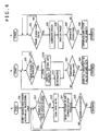
- FIG. 4 is a flowchart illustrating the operations of the system 100 for detecting an abnormality of rotating machines according to the embodiment.
- FIG. 4A illustrates an operation flow of the sampler 12.
- FIG. 4B illustrates an operation flow of the frequency analyzer 23a, the storage processing unit 23b, and the abnormality determination unit 24.
- FIG. 4C illustrates an operation flow of the image generating unit 25 and the display unit 3. The operations illustrated in FIGS. 4A-4C are performed in parallel.
- FIG. 4 illustrate a flow chart for one of the rotating machines 5 (for example, the rotating machine 5-1).
- the flow chart for the remaining rotating machines 5 is the same as in FIG. 4 .
- the arithmetic processing unit 2 (the controller 23c) outputs an instruction to the sampler 12 to start sampling and A/D conversion of the signals transmitted by the transmitting unit 6.
- the sensors 10 detect vibration of the rotating machines 5, the amplifiers 11 amplify signals, the transmitting unit 6 transmits the signals to the sampler 12, and the sampler 12 samples and A/D-converts the transmitted signals and stores the sampled data Da in the register 12a (Step S11). From this point, the number of the sampled and A/D-converted data Da stored in the register 12a (hereinafter also referred to as "the number of the A/D-converted data received”) begins increasing from zero.
- Step S13 determines whether the number of the A/D-converted data received has reached the predetermined number as described above (102,400 signals for the AE data and 65,536 signals for the acceleration data) (Step S13). If the number of data stored is smaller than the predetermined number (NO in Step S13), the determination in Step S13 is performed again, during which the sampled data Da are stored in the register 12a to increase the number of the A/D-converted data received.
- Step S13 If the number of data stored has reached the predetermined number (YES in Step S13), all of the sampled data Da sent from the register 12a to the arithmetic processing unit 2 (the memory 21) within the predetermined period are outputted at a time (at intervals of the predetermined period) (Step S15). Then, the number of the A/D-converted data received is reset (Step S17), and the controller 23c determines whether the input unit (termination instruction input unit) 4 has received an instruction to terminate detection of abnormality from an operator (Step S19).
- Step S19 If the input unit 4 has not received an instruction to terminate detection of abnormality from an operator (NO in Step S19), the operation flow goes back to Step S13 to repeat the operations such as the operation of outputting, at a time at intervals of a predetermined period, the plurality of the sampled data Da detected within the predetermined period in Step S15. If the input unit 4 has received an instruction to terminate detection of abnormality from an operator (YES in Step S19), the system 100 for detecting an abnormality performs a predetermined near-final process and then terminates detection of abnormality.
- the controller 23c determines whether all of the sampled data Da sent from the register 12a within the predetermined period, the data being for frequency analysis, are stored in the memory 21 (Step S21). If the controller 23c has determined that the data are not stored (NO in Step S21), the operation flow goes back to Step S21. If the controller 23c has determined that the data are stored (YES in Step S21), the frequency analyzer 23a analyzes the frequencies of all of the sampled data Da sent within the predetermined period at intervals of the predetermined period (for example, sufficient time intervals such as 1 sec to ascertain the tendency (trend) of the results of the frequency analysis) (Step S23a).
- the storage processing unit 23b stores, on the HDD 22, all of the sampled data Da sent within the predetermined period (Step S23b).
- the abnormality determination unit 24 uses the results of the frequency analysis to determine presence of an abnormality of a component such as a rotor of the rotating machines 5 (Step S25).
- the controller 23c determines whether the input unit (termination instruction input unit) 4 has received an instruction to terminate detection of abnormality from an operator (Step S27). If the input unit 4 has not received an instruction to terminate detection of abnormality from an operator (NO in Step S27), the operation flow goes back to Step S21.
- the system 100 for detecting an abnormality performs a predetermined near-final process and then terminates detection of abnormality.
- the frequency analyzer 23a reads the sampled data Da at all of the time points from the HDD 22 to perform the frequency analysis and outputs the results of the frequency analysis to the image generating unit 25 (Step S29).
- the image generating unit 25 determines whether the data of the results of the frequency analysis have been inputted (Step S31). If the data of the result of frequency analysis has not been inputted (NO in Step S31), the operation flow goes back to Step S31. If the data of the results of the frequency analysis have been inputted (YES in Step S31), the image generating unit 25 generates the image data for the display screen 31 (Step S33) and outputs the image data to the display unit 3, which displays the image data (Step S35). If the result of abnormality determination by the abnormality determination unit 24 is inputted to the image generating unit 25, the image generating unit 25 also uses the result of the abnormality determination to generate the image data for the display screen 31.
- the controller 23c determines whether the input unit 4 (termination instruction input unit 4a) has received an instruction to terminate detection of abnormality from an operator (Step S37). If the input unit 4 has not received an instruction to terminate detection of abnormality from an operator (NO in Step S37), the operation flow goes back to Step S31. If the input unit 4 has received an instruction to terminate detection of abnormality from an operator (YES in Step S37), the system 100 for detecting an abnormality performs a predetermined near-final process and then terminates detection of abnormality.
- the image generating unit 25 receives the results of the frequency analysis (the amplitude data) at all of the time points by the frequency analyzer 23a, then generates the three-dimensional image data for the results of the frequency analysis (the amplitude data) at all of the time points, and transmits the image data to the HDD 22 (Step S39).
- the generation of the three-dimensional image data for the results of the frequency analysis at all of the time points in this manner and transmission of the image data to the the HDD 22 in the predetermined near-final process can result in a reduction in the processing load for storage on the HDD 22 via the controller 23c, compared with a case in which a result of the frequency analysis is stored on the HDD 22 every time a result of frequency analysis is provided during the frequency analysis.
- the results of the frequency analysis of the sampled data that are created by sampling and detecting vibration of the respective n rotating machines 5-1 to 5-n are displayed in chronological order and in real time, and thus the operating states of the rotating machines 5 at respective times are displayed substantially in real time, which allows an operator to recognize a change in operation states of the rotating machines 5 over time, thereby allowing early detection of an abnormality of the rotating machines 5.
- the results of the frequency analysis and the results of the abnormality determination for the respective n rotating machines 5-1 to 5-n are displayed on the single display unit 3, which allows collective control of detection of an abnormality of the respective n rotating machines 5-1 to 5-n.
- the embodiment allows a reduction in the number of people who manage the process of detecting an abnormality of the n rotating machines 5-1 to 5-n.
- the sampler 12 is disposed outside of the arithmetic processing unit 2 in the above embodiment, the sampler 12 may be disposed in the arithmetic processing unit 2.
- the input unit 4 receives an instruction to terminate detection of abnormality from an operator before storing, on the HDD 22, the image data that show the results of the frequency analysis and that are generated by the image generating unit 25 in the above embodiment, the frequency analyzer 23a may store the results of the frequency analysis on the HDD 22 every time the results of frequency analysis is provided (as shown by the dashed arrow in FIG. 1 ).
- the frequency analyzer 23a may start storing the results of frequency analysis on the HDD 22.
- the control and arithmetic unit 23 may be configured to execute an abnormality detection program stored in ROM so that elements such as the abnormality determination unit 24 and the image generating unit 25 are functionally configured in the control and arithmetic unit 23.
- FIG. 5 is a block diagram illustrating an exemplary configuration of a system 101 for detecting an abnormality of rotating machines according to the modification of the above embodiment.
- the system includes a single pair of the arithmetic processing unit 2 and the sampler 12, and the pair performs frequency analysis for the respective n rotating machines 5-1 to 5-n.
- the n rotating machines 5-1 to 5-n are divided into a plurality of groups (such as a group of the rotating machines 5-1 to 5-h ....
- each of the pairs processes a smaller volume of data and thus can analyze frequency at higher speeds, compared with the system 100 for detecting an abnormality of rotating machines according to the embodiment.
Landscapes
- Physics & Mathematics (AREA)
- Engineering & Computer Science (AREA)
- General Physics & Mathematics (AREA)
- Chemical & Material Sciences (AREA)
- General Health & Medical Sciences (AREA)
- Signal Processing (AREA)
- Pathology (AREA)
- Immunology (AREA)
- Health & Medical Sciences (AREA)
- Life Sciences & Earth Sciences (AREA)
- Analytical Chemistry (AREA)
- Biochemistry (AREA)
- Mechanical Engineering (AREA)
- General Engineering & Computer Science (AREA)
- Acoustics & Sound (AREA)
- Mathematical Physics (AREA)
- Spectroscopy & Molecular Physics (AREA)
- Aviation & Aerospace Engineering (AREA)
- Combustion & Propulsion (AREA)
- Testing Of Devices, Machine Parts, Or Other Structures Thereof (AREA)
- Measurement Of Mechanical Vibrations Or Ultrasonic Waves (AREA)
- Testing And Monitoring For Control Systems (AREA)
Claims (8)
- Système (100) pour détecter une anomalie de machines tournantes (5), le système (100) comprenant :deux dispositifs ou plus (7), pour détecter une anomalie de deux machines tournantes ou plus (5) auxquelles les dispositifs (7) sont respectivement affectés ; etun ordinateur (8) ;dans lequel les deux dispositifs respectifs ou plus (7) pour détecter une anomalie comprennent chacun :un capteur (10) pour détecter une vibration d'une machine tournante (5) à laquelle le capteur (10) est affecté, et générer un signal indicatif de la vibration détectée ; etune unité de transmission (6) pour transmettre, à l'ordinateur (8), les signaux générés par le capteur (10) ; etdans lequel l'ordinateur (8) comprend :un échantillonneur (12) adapté pour échantillonner et détecter, avec une fréquence d'échantillonnage prédéterminée, les signaux qui sont transmis par l'unité de transmission (6) des deux dispositifs respectifs ou plus (7) pour détecter une anomalie, et qui sont indicatifs de la vibration, et fournir en sortie, ponctuellement, à des intervalles d'une période prédéterminée, une pluralité des données échantillonnées détectées au cours de la période prédéterminée ;une mémoire (21, 22) pour stocker la pluralité des données échantillonnées qui sont fournies en sortie par l'échantillonneur (12) et qui correspondent aux deux machines tournantes respectives ou plus (5) ;un analyseur de fréquence (23a) pour analyser les fréquences de la pluralité des données échantillonnées qui sont fournies en sortie par l'échantillonneur (12) et qui correspondent aux deux machines tournantes respectives ou plus (5) ;une unité de détermination d'anomalie (24) pour déterminer si les deux machines tournantes respectives ou plus (5) présentent une anomalie, sur la base des résultats de l'analyse de fréquence mise en oeuvre par l'analyseur de fréquence (23a), les résultats correspondant aux deux machines tournantes respectives ou plus (5) ;caractérisé par :une unité de génération d'image (25) pour générer des données d'image montrant les résultats bidimensionnels, dans la dimension de fréquence et la dimension d'amplitude, de l'analyse de fréquence, au point temporel le plus courant, et aux points temporels précédents dans l'ordre chronologique ; etune unité d'affichage (3) adaptée pour afficher, dans l'ordre chronologique, et en temps réel, une image, selon les données d'image générées par l'unité de génération d'image (25) montrant les résultats de l'analyse de fréquence, les résultats correspondant aux deux machines tournantes respectives ou plus (5), et afficher les résultats de la détermination ;dans lequel l'analyseur de fréquence (23a) est adapté pour initier l'analyse de fréquence lorsque l'analyseur de fréquence (23a) a reçu la pluralité des données échantillonnées en provenance de l'unité de détection ; etdans lequel la période d'analyse depuis l'initiation de l'analyse de fréquence jusqu'à la fin de l'analyse de fréquence est plus courte que la période prédéterminée.
- Système (100) pour détecter une anomalie de machines tournantes (5) selon la revendication 1, dans lequel l'analyseur de fréquence (23a) est adapté pour analyser les fréquences de la pluralité des données échantillonnées par le biais d'une transformée de Fourier rapide, et fournit en sortie des données d'amplitude correspondant aux fréquences respectives.
- Système (100) pour détecter une anomalie de machines tournantes (5) selon la revendication 1,
dans lequel la mémoire (21, 22) est adapté pour initier le stockage de la pluralité des données échantillonnées et des résultats de l'analyse de fréquence lorsque la mémoire (21, 22) a reçu la pluralité des données échantillonnées en provenance de l'unité de détection ; et
dans lequel la période de stockage depuis l'initiation du stockage de la pluralité des données échantillonnées jusqu'à la fin du stockage est plus courte que la période prédéterminée. - Système (100) pour détecter une anomalie de machines tournantes (5) selon la revendication 1,
dans lequel le système (100) comprend en outre une unité d'entrée d'instruction de fin (4) pour recevoir une instruction visant à mettre fin à la détection d'anomalie ;
dans lequel, lorsque l'unité d'entrée d'instruction de fin (4) a reçu l'instruction, l'analyseur de fréquence (23a) est adapté pou lire la totalité de la pluralité des données échantillonnées stockées dans la mémoire (21, 22), analyser ensuite la fréquence des données, et stocker les résultats de l'analyse de fréquence, dans l'ordre chronologique, dans la mémoire (21, 22). - Système (100) pour détecter une anomalie de machines tournantes (5) selon l'une quelconque des revendications 1 et 2 ;
dans lequel la mémoire (21, 22) est adaptée pour initier le stockage de la pluralité des données échantillonnées et des résultats de l'analyse de fréquence lorsque la mémoire (21, 22) a reçu la pluralité des données échantillonnées en provenance de l'unité de détection ; et
dans lequel la période de stockage, depuis l'initiation du stockage de la pluralité des données échantillonnées jusqu'à la fin du stockage, est plus courte que la période prédéterminée. - Système (100) pour détecter une anomalie de machines tournantes (5) selon l'une quelconque des revendications 1 et 2,
dans lequel le système (100) comprend en outre une unité d'entrée d'instruction de fin (4) pour recevoir une instruction visant à mettre fin à la détection d'anomalie ;
dans lequel, lorsque l'unité d'entrée d'instruction de fin (4) a reçu l'instruction, l'analyseur de fréquence (23a) est adapté pour lire la totalité de la pluralité des données échantillonnées stockées dans la mémoire (21, 22), analyser ensuite la fréquence des données, et stocker les résultats de l'analyse de fréquence dans l'ordre chronologique dans la mémoire (21, 22). - Système (100) pour détecter une anomalie de machines tournantes (5) selon l'une quelconque des revendications 3 à 6,
dans lequel l'analyseur de fréquence (23a) est configuré fonctionnellement dans un processeur en exécutant un programme d'analyse de fréquence prédéterminé ; et
dans lequel, lors du démarrage de l'analyse de fréquence, l'analyseur de fréquence (23a) est configuré fonctionnellement dans le processeur, tandis qu'une fois que l'analyse de fréquence est terminée, l'analyseur de fréquence (23a) est libéré du processeur. - Procédé de détection d'une anomalie de deux machines tournantes ou plus (5) au moyen de deux dispositifs ou plus (7) pour détecter une anomalie des deux machines tournantes ou plus (5) auxquelles les dispositifs (7) sont respectivement affectés, le procédé comprenant :une étape consistant à détecter (S11) une vibration des machines tournantes (5) auxquelles les dispositifs (7) sont affectés, et à générer des signaux indicatifs de la vibration détectée par les deux dispositifs respectifs ou plus (7) pour détecter une anomalie ;une étape consistant à transmettre (S11) les signaux générés à l'étape de génération par le biais des deux dispositifs respectifs ou plus (7) pour détecter une anomalie ;une étape consistant à échantillonner et à détecter (S11), avec une fréquence d'échantillonnage prédéterminée, les signaux qui sont transmis à l'étape de transmission, par le biais des deux dispositifs respectifs ou plus (7) pour détecter une anomalie, et qui sont indicatifs de la vibration, et à fournir en sortie, ponctuellement, à des intervalles d'une période prédéterminée, une pluralité des données échantillonnées détectées au cours de la période prédéterminée ;une étape consistant à stocker (S11) la pluralité des données échantillonnées qui sont fournies en sortie à l'étape d'échantillonnage et qui correspondent aux deux machines tournantes respectives ou plus (5) ;une étape consistant à analyser (S23a) des fréquences de la pluralité des données échantillonnées qui sont fournies en sortie à l'étape d'échantillonnage et qui correspondent aux deux machines tournantes respectives ou plus (5) ;une étape consistant à déterminer (S25) si les deux machines tournantes respectives ou plus (5) présentent une anomalie sur la base des résultats de l'analyse de fréquence mise en oeuvre à l'étape d'analyse de fréquence, les résultats correspondant aux deux machines tournantes respectives ou plus (5) ;caractérisé par :une étape consistant à générer (S33) des données d'image montrant les résultats bidimensionnels, dans la dimension de fréquence et la dimension d'amplitude, de l'analyse de fréquence, au point temporel le plus courant, et aux points temporels précédents dans l'ordre chronologique pour l'écran d'affichage (31) ;une étape consistant à afficher (S35), dans l'ordre chronologique et en temps réel, une image selon les données d'image générées montrant les résultats de l'analyse de fréquence, les résultats correspondant aux deux machines tournantes respectives ou plus (5), et à afficher les résultats de la détermination ;dans lequel l'étape d'analyse (23a) initie l'analyse de fréquence une fois la pluralité des données échantillonnées reçue ; etdans lequel la période d'analyse, depuis l'initiation de l'analyse de fréquence jusqu'à la fin de l'analyse de fréquence, est plus courte que la période prédéterminée.
Applications Claiming Priority (1)
| Application Number | Priority Date | Filing Date | Title |
|---|---|---|---|
| JP2016023882A JP6573838B2 (ja) | 2016-02-10 | 2016-02-10 | 回転機の異常検知システム |
Publications (2)
| Publication Number | Publication Date |
|---|---|
| EP3206003A1 EP3206003A1 (fr) | 2017-08-16 |
| EP3206003B1 true EP3206003B1 (fr) | 2019-09-25 |
Family
ID=58017880
Family Applications (1)
| Application Number | Title | Priority Date | Filing Date |
|---|---|---|---|
| EP16207234.2A Active EP3206003B1 (fr) | 2016-02-10 | 2016-12-29 | Système et dispositif de détection d'anomalie de machines tournantes |
Country Status (4)
| Country | Link |
|---|---|
| US (1) | US10422774B2 (fr) |
| EP (1) | EP3206003B1 (fr) |
| JP (1) | JP6573838B2 (fr) |
| CN (1) | CN107063427B (fr) |
Families Citing this family (14)
| Publication number | Priority date | Publication date | Assignee | Title |
|---|---|---|---|---|
| JP2019179395A (ja) * | 2018-03-30 | 2019-10-17 | オムロン株式会社 | 異常検知システム、サポート装置および異常検知方法 |
| JP6456580B1 (ja) * | 2018-06-14 | 2019-01-23 | 三菱電機株式会社 | 異常検知装置、異常検知方法及び異常検知プログラム |
| CN109269628B (zh) * | 2018-08-01 | 2021-12-24 | 瑞声科技(新加坡)有限公司 | 监测马达振动的方法、终端设备以及计算机可读存储介质 |
| EP3708991A1 (fr) * | 2019-03-14 | 2020-09-16 | Siemens Aktiengesellschaft | Classificateur automatisé de l'état de santé pour machines rotatives sur la base de connaissances expertes |
| CN110146156B (zh) * | 2019-06-27 | 2021-02-09 | 南昌航空大学 | 一种航空发动机转子系统故障振动信号的去噪方法 |
| US11415139B2 (en) * | 2019-07-08 | 2022-08-16 | Purdue Research Foundation | Compressor stall warning using nonlinear feature extraction algorithms |
| JP7594599B2 (ja) * | 2020-09-25 | 2024-12-04 | 株式会社バルカー | 振動解析システム、および振動解析方法 |
| JP7528677B2 (ja) * | 2020-09-28 | 2024-08-06 | セイコーエプソン株式会社 | 信号処理方法、信号処理装置及び監視システム |
| JP7120486B1 (ja) * | 2020-12-10 | 2022-08-17 | 住友電気工業株式会社 | 処理システム、表示システム、処理装置、処理方法および処理プログラム |
| CN113791727B (zh) * | 2021-08-10 | 2023-03-24 | 广东省科学院智能制造研究所 | 一种应用于工业声学智能感知的边端采集设备 |
| DE102021128065A1 (de) * | 2021-10-28 | 2023-05-04 | MTU Aero Engines AG | Verfahren zum Erkennen einer Anomalie in Betriebsmesswerten einer Strömungsmaschine und Analysevorrichtung und Maschinenüberwachungsvorrichtung |
| FR3132901A1 (fr) * | 2022-02-21 | 2023-08-25 | Airbus Operations (S.A.S). | Procédé de détection de vibrations issues d’une machine tournante d’un aéronef. |
| CN116717493B (zh) * | 2023-07-20 | 2024-03-15 | 东莞市绿雅家用电器有限公司 | 一种基于超声动态感知的便携风扇控制方法及系统 |
| EP4579451A1 (fr) * | 2023-12-26 | 2025-07-02 | Canon Kabushiki Kaisha | Terminal de communication, procédé de commande et support d'informations |
Family Cites Families (33)
| Publication number | Priority date | Publication date | Assignee | Title |
|---|---|---|---|---|
| WO1981002785A1 (fr) * | 1980-03-26 | 1981-10-01 | Kawasaki Steel Co | Dispositif de controle pour une machine rotative |
| JPS57184932A (en) * | 1981-05-09 | 1982-11-13 | Mitsubishi Electric Corp | Monitor device for vibration |
| JPS63150633A (ja) | 1986-12-16 | 1988-06-23 | Toshiba Corp | 軸振動診断装置 |
| JPH08166330A (ja) | 1994-12-15 | 1996-06-25 | Hitachi Ltd | 回転機械の異常摺動診断方法とその装置、及び非接触型スクリュー圧縮機の異常摺動診断方法とその装置 |
| JP4006820B2 (ja) * | 1998-04-22 | 2007-11-14 | 松下電器産業株式会社 | 感震装置 |
| US5965819A (en) * | 1998-07-06 | 1999-10-12 | Csi Technology | Parallel processing in a vibration analyzer |
| JP3685367B2 (ja) * | 1999-05-24 | 2005-08-17 | 三菱電機株式会社 | 回転電機の異常検出装置 |
| JP3630041B2 (ja) * | 1999-10-25 | 2005-03-16 | 株式会社日立製作所 | ウェーブレット変換によるプラント機器監視装置 |
| JP4801912B2 (ja) * | 2004-03-24 | 2011-10-26 | 株式会社東芝 | 超音波診断装置 |
| JP2006077938A (ja) * | 2004-09-13 | 2006-03-23 | Nsk Ltd | 異常診断装置 |
| CN101201295A (zh) * | 2006-12-13 | 2008-06-18 | 上海海事大学 | 旋转机械小波灰色故障预测方法及装置 |
| JP2008232934A (ja) * | 2007-03-22 | 2008-10-02 | Jfe Advantech Co Ltd | 設備診断システム |
| JP2008268187A (ja) * | 2007-03-26 | 2008-11-06 | Nippon Steel Corp | 極低速回転機械の異常診断方法及び装置 |
| DE202008014792U1 (de) * | 2008-11-07 | 2010-03-25 | Qass Gmbh | Vorrichtung zum Bewerten von Zerspanungsprozessen |
| JP5487681B2 (ja) * | 2009-03-31 | 2014-05-07 | Jfeスチール株式会社 | 鋼帯圧延機診断装置及び診断方法 |
| JP5460160B2 (ja) * | 2009-07-22 | 2014-04-02 | Jfeメカニカル株式会社 | 設備機器の診断装置 |
| JP4881997B2 (ja) * | 2009-12-17 | 2012-02-22 | アンリツ株式会社 | スペクトラムアナライザおよびスペクトラム分析方法 |
| JP5725833B2 (ja) * | 2010-01-04 | 2015-05-27 | Ntn株式会社 | 転がり軸受の異常診断装置、風力発電装置および異常診断システム |
| CN201637483U (zh) | 2010-01-27 | 2010-11-17 | 北京信息科技大学 | 一种旋转设备故障预测装置 |
| DE202010007655U1 (de) * | 2010-06-07 | 2011-09-08 | Ulrich Seuthe | Vorrichtung zur Überwachung und Optimierung von Spritzgießprozessen |
| CN102121967B (zh) * | 2010-11-20 | 2013-03-27 | 太原理工大学 | 一种三相旋转机电设备运行状态实时预测诊断器 |
| EP2732251B1 (fr) * | 2011-07-14 | 2019-03-13 | S.P.M. Instrument AB | Procédé et système d'analyse de l'état d'une pièce rotative d'une machine |
| JP5738711B2 (ja) * | 2011-07-29 | 2015-06-24 | 株式会社東芝 | 回転機械状態監視装置、回転機械状態監視方法及び回転機械状態監視プログラム |
| US9625354B2 (en) * | 2011-09-21 | 2017-04-18 | Globalfoundries Inc. | Detecting occurrence of abnormality |
| FR2986070B1 (fr) * | 2012-01-24 | 2014-11-28 | Snecma | Systeme d'acquisition d'un signal vibratoire d'un moteur rotatif |
| JP6475906B2 (ja) * | 2012-11-29 | 2019-02-27 | 株式会社サタケ | 籾摺機のモニタリング装置 |
| JP5653993B2 (ja) * | 2012-12-19 | 2015-01-14 | 日本電信電話株式会社 | 柱状構造物の異常検知システムおよび異常検知方法 |
| JP5985996B2 (ja) * | 2013-01-18 | 2016-09-06 | 泉工医科工業株式会社 | エアリーク検出装置及びそれを備えた電動式吸引器 |
| CN103162816B (zh) * | 2013-02-28 | 2015-06-24 | 唐山开诚电控设备集团有限公司 | 一种基于传感器的振动监测方法 |
| US9778080B2 (en) * | 2013-04-29 | 2017-10-03 | Emerson Electric (Us) Holding Corporation (Chile) Limitada | Selective decimation and analysis of oversampled data |
| CN103644966B (zh) * | 2013-12-29 | 2015-06-17 | 中国科学技术大学 | 一种周期信号增强检测装置及方法 |
| CN204495460U (zh) * | 2014-11-06 | 2015-07-22 | 广西电网公司电力科学研究院 | 变压器机械振动波谱在线监测系统 |
| WO2016143118A1 (fr) * | 2015-03-12 | 2016-09-15 | 株式会社日立製作所 | Dispositif de diagnostic de machine et procédé de diagnostic de machine |
-
2016
- 2016-02-10 JP JP2016023882A patent/JP6573838B2/ja not_active Expired - Fee Related
- 2016-12-28 US US15/392,592 patent/US10422774B2/en active Active
- 2016-12-29 EP EP16207234.2A patent/EP3206003B1/fr active Active
-
2017
- 2017-02-08 CN CN201710070080.1A patent/CN107063427B/zh not_active Expired - Fee Related
Non-Patent Citations (1)
| Title |
|---|
| None * |
Also Published As
| Publication number | Publication date |
|---|---|
| US20170227505A1 (en) | 2017-08-10 |
| EP3206003A1 (fr) | 2017-08-16 |
| JP2017142179A (ja) | 2017-08-17 |
| CN107063427B (zh) | 2020-06-30 |
| JP6573838B2 (ja) | 2019-09-11 |
| CN107063427A (zh) | 2017-08-18 |
| US10422774B2 (en) | 2019-09-24 |
Similar Documents
| Publication | Publication Date | Title |
|---|---|---|
| EP3206003B1 (fr) | Système et dispositif de détection d'anomalie de machines tournantes | |
| US10352760B2 (en) | Device and system for detecting malfunction of rotating machine | |
| CN106662505B (zh) | 旋转机的异常检测装置及其方法和系统以及旋转机 | |
| CN100480648C (zh) | 用于振动感测和分析的方法和仪器 | |
| EP3605036B1 (fr) | Analyseur de vibrations et système de diagnostic d'élément de machine | |
| JP6223935B2 (ja) | 回転機械異常検出装置および該方法ならびに回転機 | |
| JP2003528292A (ja) | 振動解析によるベアリングの状態ベースのモニタリング | |
| US7168324B2 (en) | Vibration information transmission apparatus and vibration monitoring/analyzing system | |
| JP2002268728A (ja) | 同期診断監視システム、同期診断監視装置、および同期診断監視プログラム | |
| WO2020162426A1 (fr) | Dispositif d'analyse, procédé d'analyse, programme et structure de capteur | |
| WO2015011791A1 (fr) | Système d'évaluation de détection d'anomalie | |
| JP3920715B2 (ja) | 振動信号の処理方法 | |
| JPH04204021A (ja) | 回転機械振動・音響診断装置 | |
| US8880364B2 (en) | Method and apparatus for detection of short stress waves | |
| CN119354541A (zh) | 一种振动测量旋转机械诊断方法、系统、装置及存储介质 | |
| JP7518808B2 (ja) | 診断方法、診断プログラム、および診断装置 | |
| JP5321646B2 (ja) | 異常検査方法及び異常検査装置 | |
| JP3776343B2 (ja) | 異常監視装置 | |
| JP2025002167A (ja) | 軸受分析装置、軸受分析方法、プログラム、および、プログラム記憶媒体 | |
| JP2024031072A (ja) | 監視装置、監視方法、及び監視プログラム | |
| JP2026059255A (ja) | 監視装置、監視システム、および、監視方法 |
Legal Events
| Date | Code | Title | Description |
|---|---|---|---|
| PUAI | Public reference made under article 153(3) epc to a published international application that has entered the european phase |
Free format text: ORIGINAL CODE: 0009012 |
|
| STAA | Information on the status of an ep patent application or granted ep patent |
Free format text: STATUS: REQUEST FOR EXAMINATION WAS MADE |
|
| 17P | Request for examination filed |
Effective date: 20161229 |
|
| AK | Designated contracting states |
Kind code of ref document: A1 Designated state(s): AL AT BE BG CH CY CZ DE DK EE ES FI FR GB GR HR HU IE IS IT LI LT LU LV MC MK MT NL NO PL PT RO RS SE SI SK SM TR |
|
| AX | Request for extension of the european patent |
Extension state: BA ME |
|
| STAA | Information on the status of an ep patent application or granted ep patent |
Free format text: STATUS: EXAMINATION IS IN PROGRESS |
|
| 17Q | First examination report despatched |
Effective date: 20180511 |
|
| GRAP | Despatch of communication of intention to grant a patent |
Free format text: ORIGINAL CODE: EPIDOSNIGR1 |
|
| STAA | Information on the status of an ep patent application or granted ep patent |
Free format text: STATUS: GRANT OF PATENT IS INTENDED |
|
| RIC1 | Information provided on ipc code assigned before grant |
Ipc: G01N 29/44 20060101ALI20190313BHEP Ipc: F02D 27/00 20060101ALI20190313BHEP Ipc: G01N 29/14 20060101ALI20190313BHEP Ipc: G01H 1/00 20060101ALI20190313BHEP Ipc: F04D 27/00 20060101ALI20190313BHEP Ipc: G01M 5/00 20060101AFI20190313BHEP Ipc: G01N 29/46 20060101ALI20190313BHEP Ipc: F01D 21/00 20060101ALI20190313BHEP |
|
| INTG | Intention to grant announced |
Effective date: 20190409 |
|
| GRAS | Grant fee paid |
Free format text: ORIGINAL CODE: EPIDOSNIGR3 |
|
| GRAA | (expected) grant |
Free format text: ORIGINAL CODE: 0009210 |
|
| STAA | Information on the status of an ep patent application or granted ep patent |
Free format text: STATUS: THE PATENT HAS BEEN GRANTED |
|
| AK | Designated contracting states |
Kind code of ref document: B1 Designated state(s): AL AT BE BG CH CY CZ DE DK EE ES FI FR GB GR HR HU IE IS IT LI LT LU LV MC MK MT NL NO PL PT RO RS SE SI SK SM TR |
|
| REG | Reference to a national code |
Ref country code: GB Ref legal event code: FG4D |
|
| REG | Reference to a national code |
Ref country code: CH Ref legal event code: EP |
|
| REG | Reference to a national code |
Ref country code: AT Ref legal event code: REF Ref document number: 1184273 Country of ref document: AT Kind code of ref document: T Effective date: 20191015 |
|
| REG | Reference to a national code |
Ref country code: IE Ref legal event code: FG4D |
|
| REG | Reference to a national code |
Ref country code: DE Ref legal event code: R096 Ref document number: 602016021180 Country of ref document: DE |
|
| REG | Reference to a national code |
Ref country code: NL Ref legal event code: MP Effective date: 20190925 |
|
| PG25 | Lapsed in a contracting state [announced via postgrant information from national office to epo] |
Ref country code: SE Free format text: LAPSE BECAUSE OF FAILURE TO SUBMIT A TRANSLATION OF THE DESCRIPTION OR TO PAY THE FEE WITHIN THE PRESCRIBED TIME-LIMIT Effective date: 20190925 Ref country code: LT Free format text: LAPSE BECAUSE OF FAILURE TO SUBMIT A TRANSLATION OF THE DESCRIPTION OR TO PAY THE FEE WITHIN THE PRESCRIBED TIME-LIMIT Effective date: 20190925 Ref country code: BG Free format text: LAPSE BECAUSE OF FAILURE TO SUBMIT A TRANSLATION OF THE DESCRIPTION OR TO PAY THE FEE WITHIN THE PRESCRIBED TIME-LIMIT Effective date: 20191225 Ref country code: NO Free format text: LAPSE BECAUSE OF FAILURE TO SUBMIT A TRANSLATION OF THE DESCRIPTION OR TO PAY THE FEE WITHIN THE PRESCRIBED TIME-LIMIT Effective date: 20191225 Ref country code: HR Free format text: LAPSE BECAUSE OF FAILURE TO SUBMIT A TRANSLATION OF THE DESCRIPTION OR TO PAY THE FEE WITHIN THE PRESCRIBED TIME-LIMIT Effective date: 20190925 |
|
| REG | Reference to a national code |
Ref country code: SE Ref legal event code: TRGR |
|
| REG | Reference to a national code |
Ref country code: LT Ref legal event code: MG4D |
|
| PG25 | Lapsed in a contracting state [announced via postgrant information from national office to epo] |
Ref country code: LV Free format text: LAPSE BECAUSE OF FAILURE TO SUBMIT A TRANSLATION OF THE DESCRIPTION OR TO PAY THE FEE WITHIN THE PRESCRIBED TIME-LIMIT Effective date: 20190925 Ref country code: GR Free format text: LAPSE BECAUSE OF FAILURE TO SUBMIT A TRANSLATION OF THE DESCRIPTION OR TO PAY THE FEE WITHIN THE PRESCRIBED TIME-LIMIT Effective date: 20191226 Ref country code: RS Free format text: LAPSE BECAUSE OF FAILURE TO SUBMIT A TRANSLATION OF THE DESCRIPTION OR TO PAY THE FEE WITHIN THE PRESCRIBED TIME-LIMIT Effective date: 20190925 |
|
| REG | Reference to a national code |
Ref country code: AT Ref legal event code: MK05 Ref document number: 1184273 Country of ref document: AT Kind code of ref document: T Effective date: 20190925 |
|
| PG25 | Lapsed in a contracting state [announced via postgrant information from national office to epo] |
Ref country code: ES Free format text: LAPSE BECAUSE OF FAILURE TO SUBMIT A TRANSLATION OF THE DESCRIPTION OR TO PAY THE FEE WITHIN THE PRESCRIBED TIME-LIMIT Effective date: 20190925 Ref country code: AT Free format text: LAPSE BECAUSE OF FAILURE TO SUBMIT A TRANSLATION OF THE DESCRIPTION OR TO PAY THE FEE WITHIN THE PRESCRIBED TIME-LIMIT Effective date: 20190925 Ref country code: PL Free format text: LAPSE BECAUSE OF FAILURE TO SUBMIT A TRANSLATION OF THE DESCRIPTION OR TO PAY THE FEE WITHIN THE PRESCRIBED TIME-LIMIT Effective date: 20190925 Ref country code: AL Free format text: LAPSE BECAUSE OF FAILURE TO SUBMIT A TRANSLATION OF THE DESCRIPTION OR TO PAY THE FEE WITHIN THE PRESCRIBED TIME-LIMIT Effective date: 20190925 Ref country code: IT Free format text: LAPSE BECAUSE OF FAILURE TO SUBMIT A TRANSLATION OF THE DESCRIPTION OR TO PAY THE FEE WITHIN THE PRESCRIBED TIME-LIMIT Effective date: 20190925 Ref country code: PT Free format text: LAPSE BECAUSE OF FAILURE TO SUBMIT A TRANSLATION OF THE DESCRIPTION OR TO PAY THE FEE WITHIN THE PRESCRIBED TIME-LIMIT Effective date: 20200127 Ref country code: EE Free format text: LAPSE BECAUSE OF FAILURE TO SUBMIT A TRANSLATION OF THE DESCRIPTION OR TO PAY THE FEE WITHIN THE PRESCRIBED TIME-LIMIT Effective date: 20190925 Ref country code: NL Free format text: LAPSE BECAUSE OF FAILURE TO SUBMIT A TRANSLATION OF THE DESCRIPTION OR TO PAY THE FEE WITHIN THE PRESCRIBED TIME-LIMIT Effective date: 20190925 Ref country code: RO Free format text: LAPSE BECAUSE OF FAILURE TO SUBMIT A TRANSLATION OF THE DESCRIPTION OR TO PAY THE FEE WITHIN THE PRESCRIBED TIME-LIMIT Effective date: 20190925 |
|
| PG25 | Lapsed in a contracting state [announced via postgrant information from national office to epo] |
Ref country code: CZ Free format text: LAPSE BECAUSE OF FAILURE TO SUBMIT A TRANSLATION OF THE DESCRIPTION OR TO PAY THE FEE WITHIN THE PRESCRIBED TIME-LIMIT Effective date: 20190925 Ref country code: IS Free format text: LAPSE BECAUSE OF FAILURE TO SUBMIT A TRANSLATION OF THE DESCRIPTION OR TO PAY THE FEE WITHIN THE PRESCRIBED TIME-LIMIT Effective date: 20200224 Ref country code: SK Free format text: LAPSE BECAUSE OF FAILURE TO SUBMIT A TRANSLATION OF THE DESCRIPTION OR TO PAY THE FEE WITHIN THE PRESCRIBED TIME-LIMIT Effective date: 20190925 Ref country code: SM Free format text: LAPSE BECAUSE OF FAILURE TO SUBMIT A TRANSLATION OF THE DESCRIPTION OR TO PAY THE FEE WITHIN THE PRESCRIBED TIME-LIMIT Effective date: 20190925 |
|
| REG | Reference to a national code |
Ref country code: DE Ref legal event code: R097 Ref document number: 602016021180 Country of ref document: DE |
|
| PG2D | Information on lapse in contracting state deleted |
Ref country code: IS |
|
| PG25 | Lapsed in a contracting state [announced via postgrant information from national office to epo] |
Ref country code: DK Free format text: LAPSE BECAUSE OF FAILURE TO SUBMIT A TRANSLATION OF THE DESCRIPTION OR TO PAY THE FEE WITHIN THE PRESCRIBED TIME-LIMIT Effective date: 20190925 Ref country code: IS Free format text: LAPSE BECAUSE OF FAILURE TO SUBMIT A TRANSLATION OF THE DESCRIPTION OR TO PAY THE FEE WITHIN THE PRESCRIBED TIME-LIMIT Effective date: 20200126 |
|
| PLBE | No opposition filed within time limit |
Free format text: ORIGINAL CODE: 0009261 |
|
| REG | Reference to a national code |
Ref country code: CH Ref legal event code: PL |
|
| STAA | Information on the status of an ep patent application or granted ep patent |
Free format text: STATUS: NO OPPOSITION FILED WITHIN TIME LIMIT |
|
| REG | Reference to a national code |
Ref country code: BE Ref legal event code: MM Effective date: 20191231 |
|
| PG25 | Lapsed in a contracting state [announced via postgrant information from national office to epo] |
Ref country code: MC Free format text: LAPSE BECAUSE OF FAILURE TO SUBMIT A TRANSLATION OF THE DESCRIPTION OR TO PAY THE FEE WITHIN THE PRESCRIBED TIME-LIMIT Effective date: 20190925 |
|
| 26N | No opposition filed |
Effective date: 20200626 |
|
| PG25 | Lapsed in a contracting state [announced via postgrant information from national office to epo] |
Ref country code: FR Free format text: LAPSE BECAUSE OF NON-PAYMENT OF DUE FEES Effective date: 20191231 Ref country code: LU Free format text: LAPSE BECAUSE OF NON-PAYMENT OF DUE FEES Effective date: 20191229 Ref country code: IE Free format text: LAPSE BECAUSE OF NON-PAYMENT OF DUE FEES Effective date: 20191229 |
|
| PG25 | Lapsed in a contracting state [announced via postgrant information from national office to epo] |
Ref country code: BE Free format text: LAPSE BECAUSE OF NON-PAYMENT OF DUE FEES Effective date: 20191231 Ref country code: CH Free format text: LAPSE BECAUSE OF NON-PAYMENT OF DUE FEES Effective date: 20191231 Ref country code: LI Free format text: LAPSE BECAUSE OF NON-PAYMENT OF DUE FEES Effective date: 20191231 Ref country code: SI Free format text: LAPSE BECAUSE OF FAILURE TO SUBMIT A TRANSLATION OF THE DESCRIPTION OR TO PAY THE FEE WITHIN THE PRESCRIBED TIME-LIMIT Effective date: 20190925 |
|
| PG25 | Lapsed in a contracting state [announced via postgrant information from national office to epo] |
Ref country code: CY Free format text: LAPSE BECAUSE OF FAILURE TO SUBMIT A TRANSLATION OF THE DESCRIPTION OR TO PAY THE FEE WITHIN THE PRESCRIBED TIME-LIMIT Effective date: 20190925 |
|
| PG25 | Lapsed in a contracting state [announced via postgrant information from national office to epo] |
Ref country code: HU Free format text: LAPSE BECAUSE OF FAILURE TO SUBMIT A TRANSLATION OF THE DESCRIPTION OR TO PAY THE FEE WITHIN THE PRESCRIBED TIME-LIMIT; INVALID AB INITIO Effective date: 20161229 Ref country code: MT Free format text: LAPSE BECAUSE OF FAILURE TO SUBMIT A TRANSLATION OF THE DESCRIPTION OR TO PAY THE FEE WITHIN THE PRESCRIBED TIME-LIMIT Effective date: 20190925 |
|
| PG25 | Lapsed in a contracting state [announced via postgrant information from national office to epo] |
Ref country code: TR Free format text: LAPSE BECAUSE OF FAILURE TO SUBMIT A TRANSLATION OF THE DESCRIPTION OR TO PAY THE FEE WITHIN THE PRESCRIBED TIME-LIMIT Effective date: 20190925 |
|
| PG25 | Lapsed in a contracting state [announced via postgrant information from national office to epo] |
Ref country code: MK Free format text: LAPSE BECAUSE OF FAILURE TO SUBMIT A TRANSLATION OF THE DESCRIPTION OR TO PAY THE FEE WITHIN THE PRESCRIBED TIME-LIMIT Effective date: 20190925 |
|
| P01 | Opt-out of the competence of the unified patent court (upc) registered |
Effective date: 20230523 |
|
| PGFP | Annual fee paid to national office [announced via postgrant information from national office to epo] |
Ref country code: GB Payment date: 20231109 Year of fee payment: 8 |
|
| PGFP | Annual fee paid to national office [announced via postgrant information from national office to epo] |
Ref country code: SE Payment date: 20231110 Year of fee payment: 8 Ref country code: DE Payment date: 20231031 Year of fee payment: 8 |
|
| REG | Reference to a national code |
Ref country code: DE Ref legal event code: R119 Ref document number: 602016021180 Country of ref document: DE |
|
| REG | Reference to a national code |
Ref country code: SE Ref legal event code: EUG |
|
| GBPC | Gb: european patent ceased through non-payment of renewal fee |
Effective date: 20241229 |
|
| PG25 | Lapsed in a contracting state [announced via postgrant information from national office to epo] |
Ref country code: DE Free format text: LAPSE BECAUSE OF NON-PAYMENT OF DUE FEES Effective date: 20250701 |
|
| PG25 | Lapsed in a contracting state [announced via postgrant information from national office to epo] |
Ref country code: GB Free format text: LAPSE BECAUSE OF NON-PAYMENT OF DUE FEES Effective date: 20241229 |