EP3209985B1 - Boîtier de capteur à réponse rapide - Google Patents
Boîtier de capteur à réponse rapide Download PDFInfo
- Publication number
- EP3209985B1 EP3209985B1 EP15791157.9A EP15791157A EP3209985B1 EP 3209985 B1 EP3209985 B1 EP 3209985B1 EP 15791157 A EP15791157 A EP 15791157A EP 3209985 B1 EP3209985 B1 EP 3209985B1
- Authority
- EP
- European Patent Office
- Prior art keywords
- sensor
- internal cavity
- micro
- internal
- assembly according
- Prior art date
- Legal status (The legal status is an assumption and is not a legal conclusion. Google has not performed a legal analysis and makes no representation as to the accuracy of the status listed.)
- Active
Links
Images


Classifications
-
- G—PHYSICS
- G01—MEASURING; TESTING
- G01K—MEASURING TEMPERATURE; MEASURING QUANTITY OF HEAT; THERMALLY-SENSITIVE ELEMENTS NOT OTHERWISE PROVIDED FOR
- G01K7/00—Measuring temperature based on the use of electric or magnetic elements directly sensitive to heat ; Power supply therefor, e.g. using thermoelectric elements
- G01K7/16—Measuring temperature based on the use of electric or magnetic elements directly sensitive to heat ; Power supply therefor, e.g. using thermoelectric elements using resistive elements
-
- G—PHYSICS
- G01—MEASURING; TESTING
- G01K—MEASURING TEMPERATURE; MEASURING QUANTITY OF HEAT; THERMALLY-SENSITIVE ELEMENTS NOT OTHERWISE PROVIDED FOR
- G01K1/00—Details of thermometers not specially adapted for particular types of thermometer
- G01K1/08—Protective devices, e.g. casings
-
- G—PHYSICS
- G01—MEASURING; TESTING
- G01K—MEASURING TEMPERATURE; MEASURING QUANTITY OF HEAT; THERMALLY-SENSITIVE ELEMENTS NOT OTHERWISE PROVIDED FOR
- G01K13/00—Thermometers specially adapted for specific purposes
- G01K13/02—Thermometers specially adapted for specific purposes for measuring temperature of moving fluids or granular materials capable of flow
Definitions
- the present disclosure relates to temperature sensors, and more particularly to small temperature sensors and their packaging.
- Temperature sensors are used in a variety of applications and are often employed in environments that demand high accuracy and a fast response time, such as semiconductor processing. Additionally, these temperature sensors must be provided in relatively small packages in order to reduce their thermal impact on the specific application. Some temperature sensors are generally provided in extremely small packages, on the order of less than 0.635 cm (0.25”) in length and less than 0.254 cm (0.10”) in diameter, and with extremely tight manufacturing tolerances. These small temperature sensors are often difficult to manufacture and must be protected from damage by protective covers and other materials, which tend to decrease the response time and accuracy of the sensors.
- US 4,492,948 discloses a temperature sensor with a closed end in the form of a cap, which is designed to be in intimate thermal contact with the resistance thermometer in order to provide high thermal conductivity to allow for a rapid response of the resistance thermometer to the temperature of a surface. In other words, the temperature sensor can detect the outside temperature only through thermal conduction.
- US 7,855,632 discloses a temperature measurement probe composed of a protective sleeve and an insulator inside the sleeve which contains a sensing element.
- US 2002/071475 A1 discloses a temperature sensor with a housing that can have an open or a closed end.
- a sensor assembly is provided with a housing comprising a unitary body having a proximal end portion and a distal end portion, the distal end portion defining an internal cavity and the proximal end portion defining a plurality of internal passageways that extend and open into the internal cavity.
- a thin film resistive temperature device is disposed within the internal cavity, the thin film RTD having a pair of lead wires that extend from the thin film RTD through at least a subset of the plurality of internal passageways.
- a sensor assembly in another form, comprises a housing with a unitary body having a proximal end portion and a distal end portion.
- the distal end portion is open and defines an internal cavity exposed to an outside environment, and the proximal end portion defines a plurality of internal passageways that extend and open into the internal cavity, the plurality of internal passageways being separated by intermediate walls.
- a thin film resistive temperature device (RTD), or other micro-sensor is disposed within the internal cavity, the thin film RTD having a plurality of lead wires that extend from the thin film RTD through the plurality of internal passageways, and the thin film RTD being in contact with at least one wall of the internal cavity.
- the thin film RTD and the lead wires are secured within the housing by a thermal adhesive having a matched coefficient of thermal expansion with that of the housing and the thin film RTD substrate.
- a housing for use in positioning a thin film resistive temperature device (RTD), or other micro-sensor, comprises a unitary body having a proximal end portion and a distal end portion, the distal end portion being open and defining an internal cavity, and the proximal end portion defining a plurality of internal passageways that extend and open into the internal cavity.
- the internal cavity defines at least one surface that geometrically matches a contact surface of the thin film RTD and an internal wall separating the internal cavity from the internal passageways, wherein the thin film RTD abuts the internal wall for proper positioning within the housing.
- a sensor assembly in yet another form, comprises a housing with a body having a proximal end portion and a distal end portion, the distal end portion defining an internal cavity and the proximal end portion defining a plurality of internal passageways that extend and open into the internal cavity.
- a micro-sensor is disposed within the internal cavity, the micro-sensor having a pair of lead wires that extend from micro-sensor through at least a subset of the plurality of internal passageways.
- another housing for use in positioning a micro-sensor comprises a unitary body having a proximal end portion and a distal end portion, the distal end portion being open and defining an internal cavity, and the proximal end portion defining a plurality of internal passageways that extend and open into the internal cavity.
- the internal cavity defines at least one surface that geometrically matches a contact surface of the micro-sensor and an internal wall separating the internal cavity from the internal passageways. The micro-sensor abuts the internal wall for proper positioning within the housing.
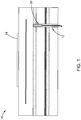
- a sensor assembly according to the present disclosure is illustrated and generally indicated by reference numeral 20, and is disposed within an exemplary semiconductor application having a chuck assembly 10.
- the sensor assembly 20, in one form, is disposed within a via 12 that extends through various members of the chuck assembly 10, in order to sense the temperature of a target, such as by way of example, a substrate 14.
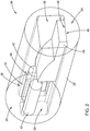
- the sensor assembly 20 generally comprises a housing 22 that in one form is a unitary body, or a one-piece member. (It should be understood, however, that the housing 22 may be provided in multiple pieces or parts while remaining within the scope of the present disclosure).
- the housing 22 defines a proximal end portion 24 and a distal end portion 26, and the distal end portion 26 in one form is open, or exposed, to an outside environment as shown.
- the distal end portion 26 defines an internal cavity 28 that is also exposed to the outside environment.
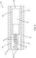
- the proximal end portion 24 defines a plurality of internal passageways 30 that extend and open into the internal cavity 28. As further shown, the plurality of internal passageways 30 are separated by an intermediate wall 32. Although only two internal passageways 30 are shown, it should be understood that any number of passageways, including three (3) and four (4) passageways to accommodate a 3-wire or 4-wire RTD, may be employed while remaining within the scope of the present disclosure.
- a micro-sensor which in this form is a thin film resistive temperature device (RTD) 40, is disposed within the internal cavity 28.
- the thin film RTD 40 is oriented as shown and also exposed to the outside environment for increased tip sensitivity.
- the thin film RTD 40 includes a plurality of lead wires 42 that extend from the thin film RTD 40 through the plurality of internal passageways 30, and the thin film RTD 40 is in contact with at least one wall 42 of the internal cavity 28.
- the lead wires 42 that extend from the thin film RTD in one form, are a smaller diameter and then transition to a larger diameter as they extend through the internal passageways 30 as shown. In one form, the lead wires 42 transition from 0.15mm to 0.40mm.
- the thin film RTD 40 and the lead wires 42 are secured within the housing 22 by a thermal adhesive, also referred to as a potting compound, having a matched coefficient of thermal expansion with that of the housing 22 and a substrate of the thin film RTD 40.
- the substrate of the thin film RTD 40 is generally the outer casing as shown, with the RTD element inside, which in this form is a ceramic casing/substrate and a platinum resistance element).
- the housing 22 is alumina
- the thermal adhesive is alumina based, along with the substrate 14.
- a glass adhesive is used to secure the thin film RTD 40 and the lead wires 42 within the housing 22.
- the glass adhesive generally provides good heat transfer and may be a material such as borosilicate. Overall, the thermal adhesive is provided for thermal conductivity, adhesion, and strain relief of the internal components (thin film RTD 40 and lead wires 42).
- micro-sensor shall be construed to mean extremely small sensors, such as a thin film RTD or a sensor employing nano particles, by way of example. Such micro-sensors have a size on the order of approximately 10mm in length by approximately 2mm in diameter, with relatively tight manufacturing tolerances, on the order of ⁇ 0.2mm. Accordingly, the present disclosure should not be construed as being limited to only thin film RTDs and may include other types of micro-sensors, either for temperature or other environmental sensing, such as by way of example, pressure or humidity.
- thermal adhesive shall be construed to mean a material or compound that secures components and with the desired heat transfer characteristics.
- a thermal adhesive may include a potting compound, glass, or other material that both bonds and transfers heat according to application requirements.
- the internal cavity 28 defines at least one surface 46 that geometrically matches a contact surface 48 of the thin film RTD 40, which in this form is flat.
- This geometric matching provides for improved heat transfer, repeatability, and response time of the thin film RTD 40.
- other geometric profiles other than flat may be employed, depending on the shape of the micro-sensor and the response time/accuracy desired. Such profiles may include, by way of example, arcuate or polygonal profiles, which are set forth below in greater detail.
- the internal cavity 28 and the internal passageways 30 in this form define a rectangular geometry.
- the internal cavity 28 defines two lateral opposed walls 50 that extend proximally to further define outer walls 52 of the internal passageways 30, which is also shown in FIG. 3 .
- the internal passageways 30 are separated by the intermediate wall 32 for electrical isolation of the lead wires 42.
- an internal wall 56 FIG. 2 and 5 ) separates the internal cavity 28 from the internal passageways 30, wherein the thin film RTD 40 in one form abuts the internal wall 56 or proper positioning within the housing 22.
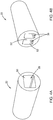
- the sensor assembly 60 includes a housing 62 that defines an internal cavity 64 that is cylindrical, and internal passageways 66 that are rectangular with arcuate end portions 68 as shown, or an oval shape. It should be understood that any number of shapes for the internal cavity and internal passageways of the housing may be employed while remaining within the scope of the present disclosure, and thus the illustration of rectangular/oval and cylindrical geometries herein should not be construed as limiting the scope of the present disclosure.
- an internal cavity 70 of a housing 72 defines a geometry that matches an outer geometric periphery 74 of the thin film RTD 40, with a relatively thin layer of thermal adhesive 76 there between.
- response time and accuracy are improved even further.
- a variety of shapes for both the internal cavity and internal passageways may be provided according to the geometry of the micro-sensor being used and the application requirements.
Landscapes
- Physics & Mathematics (AREA)
- General Physics & Mathematics (AREA)
- Testing Or Calibration Of Command Recording Devices (AREA)
- Measuring Temperature Or Quantity Of Heat (AREA)
- Measuring Volume Flow (AREA)
Claims (14)
- Ensemble capteur comprenant :un logement (22) qui comprend un corps ayant une partie d'extrémité proximale (24) et une partie d'extrémité distale (26), la partie d'extrémité distale définissant une cavité interne (28) et une ouverture et la partie d'extrémité proximale définissant une pluralité de passages internes (30) qui s'étendent et s'ouvrent dans la cavité interne (28), etun micro-capteur disposé à l'intérieur de la cavité interne (28), ayant une surface de contact (48) fixée à au moins une surface de la cavité interne, et exposée à un environnement extérieur à travers l'ouverture de la partie d'extrémité distale (26) pour accroître la sensibilité de pointe, le micro-capteur ayant une pluralité de fils conducteurs qui s'étendent depuis le micro-capteur à travers au moins un sous-ensemble de la pluralité de passages internes, dans lequel l'au moins une surface de la cavité interne (28) correspond géométriquement à la surface de contact (48) du micro-capteur.
- Ensemble capteur selon la revendication 1, dans lequel le micro-capteur est un dispositif de température résistif (RTD) à film mince.
- Ensemble capteur selon la revendication 1, dans lequel l'au moins une surface de la cavité interne (28) et la surface de contact du micro-capteur sont plates.
- Ensemble capteur selon la revendication 1, dans lequel le micro-capteur est fixé à l'intérieur de la cavité interne (28) par un adhésif thermique (76).
- Ensemble capteur selon la revendication 4, dans lequel le logement (22), l'adhésif thermique (76) et un substrat du micro-capteur ont un coefficient de dilatation thermique adapté.
- Ensemble capteur selon la revendication 1, dans lequel le corps est un corps unitaire.
- Ensemble capteur selon la revendication 1, dans lequel les fils conducteurs sont fixés à l'intérieur des passages internes (30) par un adhésif thermique.
- Ensemble capteur selon la revendication 1, dans lequel la cavité interne et les passages internes (30) définissent une géométrie cylindrique.
- Ensemble capteur selon la revendication 1, dans lequel la cavité interne et les passages internes (30) définissent une géométrie rectangulaire.
- Ensemble capteur selon la revendication 9, dans lequel la cavité interne définit deux parois latérales opposées qui s'étendent de manière proximale pour mieux définir les parois externes des passages internes (30).
- Ensemble capteur selon la revendication 1, dans lequel la cavité interne (28) définit une géométrie qui correspond à une périphérie géométrique externe du micro-capteur.
- Ensemble capteur selon la revendication 1, comprenant en outre une paroi interne séparant la cavité interne (28) des passages internes, dans lequel le micro-capteur vient en butée contre la paroi interne pour un positionnement correct à l'intérieur du logement.
- Ensemble capteur selon la revendication 1, dans lequel la partie d'extrémité distale du logement est ouverte de sorte que la cavité interne soit exposée à un environnement extérieur.
- Ensemble capteur selon la revendication 1, dans lequel le micro-capteur est un RTD à 2 fils, à 3 fils ou à 4 fils.
Applications Claiming Priority (2)
| Application Number | Priority Date | Filing Date | Title |
|---|---|---|---|
| US201462068596P | 2014-10-24 | 2014-10-24 | |
| PCT/US2015/057250 WO2016065344A1 (fr) | 2014-10-24 | 2015-10-23 | Boîtier de capteur à réponse rapide |
Publications (2)
| Publication Number | Publication Date |
|---|---|
| EP3209985A1 EP3209985A1 (fr) | 2017-08-30 |
| EP3209985B1 true EP3209985B1 (fr) | 2020-04-29 |
Family
ID=54477321
Family Applications (1)
| Application Number | Title | Priority Date | Filing Date |
|---|---|---|---|
| EP15791157.9A Active EP3209985B1 (fr) | 2014-10-24 | 2015-10-23 | Boîtier de capteur à réponse rapide |
Country Status (7)
| Country | Link |
|---|---|
| US (2) | US10571343B2 (fr) |
| EP (1) | EP3209985B1 (fr) |
| JP (1) | JP6804439B2 (fr) |
| KR (1) | KR102376169B1 (fr) |
| CN (1) | CN107076619B (fr) |
| TW (1) | TWI589848B (fr) |
| WO (1) | WO2016065344A1 (fr) |
Families Citing this family (3)
| Publication number | Priority date | Publication date | Assignee | Title |
|---|---|---|---|---|
| DE102016114963B3 (de) * | 2016-08-11 | 2018-01-11 | Endress+Hauser Flowtec Ag | Sensor für ein thermisches Durchflussmessgerät, ein thermisches Durchflussmessgerät und ein Verfahren zum Herstellen eines Sensors eines thermischen Durchflussmessgeräts |
| KR102276278B1 (ko) * | 2019-11-05 | 2021-07-12 | 주식회사 이큐셀 | 반도체 공정 진단을 위한 플라즈마 센서 장치 및 이의 제조 방법 |
| US11650106B2 (en) * | 2020-12-30 | 2023-05-16 | Rosemount Inc. | Temperature probe with improved response time |
Family Cites Families (49)
| Publication number | Priority date | Publication date | Assignee | Title |
|---|---|---|---|---|
| GB1503872A (en) | 1977-02-03 | 1978-03-15 | Rosemount Eng Co Ltd | Resistance thermometer sensors |
| US4492948A (en) * | 1981-09-02 | 1985-01-08 | Leeds & Northrup Company | Fast response surface contact temperature sensor |
| JPS58104938U (ja) * | 1982-01-11 | 1983-07-16 | トヨタ自動車株式会社 | 吸気温度センサ装置 |
| JPS5951324A (ja) * | 1983-07-25 | 1984-03-24 | Matsushita Electric Ind Co Ltd | サ−ミスタ |
| JPS6242341A (ja) | 1985-08-19 | 1987-02-24 | Toshiba Corp | 光学的情報処理装置 |
| US5022766A (en) * | 1990-01-19 | 1991-06-11 | Phipps Jack M | Temperature sensing device |
| EP0471316B1 (fr) | 1990-08-17 | 1996-09-18 | Sensycon Gesellschaft Für Industrielle Sensorsysteme Und Prozessleittechnik Mbh | Détecteur pour un débitmètre thermique |
| JPH04293201A (ja) * | 1991-03-22 | 1992-10-16 | Matsushita Electric Ind Co Ltd | 薄膜サーミスタ |
| JPH05234714A (ja) * | 1992-02-26 | 1993-09-10 | Matsushita Electric Ind Co Ltd | 接触型薄膜サーミスタとその製造方法 |
| US5300919A (en) | 1992-05-05 | 1994-04-05 | Caddock Electronics, Inc. | Vibration and shock-resistant film-type power resistor |
| US5367282A (en) * | 1992-07-21 | 1994-11-22 | Texas Instruments Incorporated | Electric motor protector sensor |
| DE4418472C2 (de) | 1994-05-20 | 1998-03-19 | Hartmann & Braun Ag | Sonde zur Temperaturmessung von Gasen oder Flüssigkeiten |
| US5999081A (en) * | 1996-11-29 | 1999-12-07 | Marchi Associates, Inc. | Shielding unique for filtering RFI and EFI interference signals from the measuring elements |
| JPH11218449A (ja) * | 1997-11-21 | 1999-08-10 | Denso Corp | 温度センサ及びその製造方法 |
| DE29913950U1 (de) | 1999-08-10 | 2000-12-21 | David & Baader DBK Spezialfabrik elektrischer Apparate und Heizwiderstände GmbH, 76870 Kandel | Temperaturfühler |
| US6341892B1 (en) * | 2000-02-03 | 2002-01-29 | George Schmermund | Resistance thermometer probe |
| US6989574B2 (en) * | 2000-08-24 | 2006-01-24 | Heetronix | High temperature circuit structures with thin film layer |
| US6588931B2 (en) * | 2000-12-07 | 2003-07-08 | Delphi Technologies, Inc. | Temperature sensor with flexible circuit substrate |
| US20060091994A1 (en) | 2001-03-19 | 2006-05-04 | Nelson Charles S | Independently housed trim resistor and a method for fabricating same |
| JP3788363B2 (ja) * | 2001-03-23 | 2006-06-21 | 株式会社デンソー | 温度センサ |
| KR100419923B1 (ko) * | 2001-05-04 | 2004-02-25 | 삼성전자주식회사 | 클린룸 온도센서장치 |
| US6666578B2 (en) | 2002-01-11 | 2003-12-23 | Eaton Corporation | RTD assembly, and temperature sensing system and excitation control system employing an RTD assembly |
| DE10233880B3 (de) | 2002-07-25 | 2004-03-04 | Beru Ag | Temperatursensor |
| JP2004239891A (ja) | 2003-01-15 | 2004-08-26 | Denso Corp | 温度センサおよびその製造方法 |
| US6918696B2 (en) | 2003-01-15 | 2005-07-19 | Denso Corporation | Temperature sensor and method for manufacturing the same |
| JP4620400B2 (ja) * | 2004-07-16 | 2011-01-26 | 日本特殊陶業株式会社 | 温度センサ、温度センサの製造方法 |
| US7855632B1 (en) * | 2005-03-02 | 2010-12-21 | Watlow Electric Manufacturing Company | Temperature sensor and method of manufacturing |
| US7147369B2 (en) * | 2005-03-28 | 2006-12-12 | Stoneridge, Inc. | Temperature sensor |
| US20090174520A1 (en) * | 2006-02-09 | 2009-07-09 | Mitsui Mining & Smelting Co., Ltd. | Laminates, Thin-Film Sensors, Thin-Film Sensor Modules, and Methods for Producing the Thin-Film Sensors |
| JP4867437B2 (ja) * | 2006-04-05 | 2012-02-01 | 株式会社デンソー | 温度センサ |
| DE102008015359A1 (de) * | 2008-03-20 | 2009-09-24 | Endress + Hauser Flowtec Ag | Temperatursensor und Verfahren zu dessen Herstellung |
| US7748267B2 (en) * | 2008-04-21 | 2010-07-06 | Sierra Insturments, Inc. | Mass flow meter with solder/braze-flow secured spacer |
| JP5198934B2 (ja) * | 2008-05-09 | 2013-05-15 | 日本特殊陶業株式会社 | 温度センサ |
| US7982580B2 (en) * | 2008-05-30 | 2011-07-19 | Rosemount Inc. | High vibration thin film RTD sensor |
| JP5455454B2 (ja) * | 2009-06-08 | 2014-03-26 | 矢崎総業株式会社 | 簡便固定機能付き温度センサとそれの搭載された電池パック送風用エアダクト |
| DE102009028850A1 (de) * | 2009-08-24 | 2011-03-03 | Endress + Hauser Flowtec Ag | Herstellungsverfahren eines Sensors eines thermischen Durchflussmessgeräts |
| CN103180703B (zh) * | 2010-09-07 | 2016-10-19 | 斯通瑞智公司 | 温度传感器和相应的发动机系统 |
| US8961007B2 (en) * | 2011-03-15 | 2015-02-24 | Siemens Energy, Inc. | Thermocouple and method of forming a thermocouple on a contoured gas turbine engine component |
| CN202008405U (zh) * | 2011-03-31 | 2011-10-12 | 北京奔龙铁道电气设备有限公司 | 铁路机车吸附式温度传感器 |
| WO2013028819A1 (fr) * | 2011-08-23 | 2013-02-28 | Stoneridge, Inc. | Capteur de température de gaz d'échappement comprenant un manchon de réduction et/ou de modification des vibrations |
| DE102011086600B4 (de) * | 2011-11-17 | 2018-01-18 | Micro-Epsilon Messtechnik Gmbh & Co. Kg | Temperatursensor |
| EP2795264A1 (fr) | 2011-12-22 | 2014-10-29 | Endress+Hauser Flowtec AG | Pièce d'écartement pour un débitmètre thermique |
| US8890678B2 (en) * | 2012-01-19 | 2014-11-18 | Rosemount Inc. | Plug-and-play sensor peripheral component for process instrumentation |
| DE102012009421A1 (de) | 2012-05-11 | 2013-11-14 | E + E Elektronik Ges.M.B.H. | Strömungssensor |
| JP6015426B2 (ja) * | 2012-12-21 | 2016-10-26 | 三菱マテリアル株式会社 | サーミスタ用金属窒化物材料及びその製造方法並びにフィルム型サーミスタセンサ |
| CN203519186U (zh) * | 2013-05-30 | 2014-04-02 | 深圳市科敏传感器有限公司 | 一种煲内温度传感器组件 |
| WO2015111094A1 (fr) * | 2014-01-21 | 2015-07-30 | 株式会社岡崎製作所 | Capteur de température pour température élevée |
| JP6075398B2 (ja) * | 2014-06-30 | 2017-02-08 | 株式会社デンソー | 温度センサ及び温度センサの製造方法 |
| JP6358154B2 (ja) * | 2015-04-08 | 2018-07-18 | 株式会社デンソー | 温度センサおよびその取り付け構造 |
-
2015
- 2015-10-23 KR KR1020177012918A patent/KR102376169B1/ko active Active
- 2015-10-23 WO PCT/US2015/057250 patent/WO2016065344A1/fr not_active Ceased
- 2015-10-23 US US14/922,075 patent/US10571343B2/en active Active
- 2015-10-23 TW TW104134934A patent/TWI589848B/zh active
- 2015-10-23 JP JP2017521487A patent/JP6804439B2/ja active Active
- 2015-10-23 CN CN201580057263.9A patent/CN107076619B/zh active Active
- 2015-10-23 EP EP15791157.9A patent/EP3209985B1/fr active Active
-
2020
- 2020-01-17 US US16/746,150 patent/US11029217B2/en active Active
Non-Patent Citations (1)
| Title |
|---|
| None * |
Also Published As
| Publication number | Publication date |
|---|---|
| JP6804439B2 (ja) | 2020-12-23 |
| US20200149977A1 (en) | 2020-05-14 |
| KR20170072252A (ko) | 2017-06-26 |
| EP3209985A1 (fr) | 2017-08-30 |
| JP2017532566A (ja) | 2017-11-02 |
| KR102376169B1 (ko) | 2022-03-18 |
| TW201623928A (zh) | 2016-07-01 |
| US11029217B2 (en) | 2021-06-08 |
| CN107076619B (zh) | 2021-01-22 |
| TWI589848B (zh) | 2017-07-01 |
| US20160116347A1 (en) | 2016-04-28 |
| US10571343B2 (en) | 2020-02-25 |
| CN107076619A (zh) | 2017-08-18 |
| WO2016065344A1 (fr) | 2016-04-28 |
Similar Documents
| Publication | Publication Date | Title |
|---|---|---|
| JP6861601B2 (ja) | 統合された圧力および温度センサ | |
| US11415466B2 (en) | Temperature measuring device and method for determining temperature | |
| US11029217B2 (en) | Rapid response sensor housing | |
| US7320544B2 (en) | Conducting structure and electronic clinical thermometer embodying the structure | |
| US11073429B2 (en) | Non-invasive process fluid temperature indication for high temperature applications | |
| EP2420807B1 (fr) | Capteur de température | |
| US11802799B2 (en) | Temperature measuring device and method for determining temperature | |
| CN104977098A (zh) | 一种响应速度快的高灵敏度光纤光栅温度传感器 | |
| US10247615B2 (en) | Sensor assemblies and methods of making same | |
| CN115479693A (zh) | 具有绝缘壳体的温度传感器装置 | |
| CN103792014B (zh) | 温度传感器 | |
| CN221284706U (zh) | 加热组件及气溶胶生成装置 | |
| US8118485B2 (en) | Very high speed thin film RTD sandwich | |
| CN222704192U (zh) | 一种防水温度传感器 | |
| US9188494B2 (en) | Measurement of fluid temperatures | |
| US10018513B1 (en) | Thermowell extension | |
| CN207503741U (zh) | Ptc陶瓷热敏电阻 | |
| CN211317564U (zh) | 一种用于ntc热敏电阻的封装及ntc热敏电阻 | |
| JPS6239306Y2 (fr) | ||
| EP3376190B1 (fr) | Capteur de température et dispositif de détection de position | |
| CN119687994A (zh) | 用于测量动态温度和压力的复合传感器及其制备方法 | |
| BR102022011578A2 (pt) | Dispositivo de sensor de temperatura com alojamento isolante | |
| JPH03103731A (ja) | 耐熱衝撃性測温抵抗体 |
Legal Events
| Date | Code | Title | Description |
|---|---|---|---|
| STAA | Information on the status of an ep patent application or granted ep patent |
Free format text: STATUS: THE INTERNATIONAL PUBLICATION HAS BEEN MADE |
|
| PUAI | Public reference made under article 153(3) epc to a published international application that has entered the european phase |
Free format text: ORIGINAL CODE: 0009012 |
|
| STAA | Information on the status of an ep patent application or granted ep patent |
Free format text: STATUS: REQUEST FOR EXAMINATION WAS MADE |
|
| 17P | Request for examination filed |
Effective date: 20170414 |
|
| AK | Designated contracting states |
Kind code of ref document: A1 Designated state(s): AL AT BE BG CH CY CZ DE DK EE ES FI FR GB GR HR HU IE IS IT LI LT LU LV MC MK MT NL NO PL PT RO RS SE SI SK SM TR |
|
| AX | Request for extension of the european patent |
Extension state: BA ME |
|
| DAV | Request for validation of the european patent (deleted) | ||
| DAX | Request for extension of the european patent (deleted) | ||
| STAA | Information on the status of an ep patent application or granted ep patent |
Free format text: STATUS: EXAMINATION IS IN PROGRESS |
|
| 17Q | First examination report despatched |
Effective date: 20180720 |
|
| GRAP | Despatch of communication of intention to grant a patent |
Free format text: ORIGINAL CODE: EPIDOSNIGR1 |
|
| STAA | Information on the status of an ep patent application or granted ep patent |
Free format text: STATUS: GRANT OF PATENT IS INTENDED |
|
| INTG | Intention to grant announced |
Effective date: 20200113 |
|
| GRAS | Grant fee paid |
Free format text: ORIGINAL CODE: EPIDOSNIGR3 |
|
| GRAJ | Information related to disapproval of communication of intention to grant by the applicant or resumption of examination proceedings by the epo deleted |
Free format text: ORIGINAL CODE: EPIDOSDIGR1 |
|
| GRAL | Information related to payment of fee for publishing/printing deleted |
Free format text: ORIGINAL CODE: EPIDOSDIGR3 |
|
| STAA | Information on the status of an ep patent application or granted ep patent |
Free format text: STATUS: EXAMINATION IS IN PROGRESS |
|
| GRAR | Information related to intention to grant a patent recorded |
Free format text: ORIGINAL CODE: EPIDOSNIGR71 |
|
| STAA | Information on the status of an ep patent application or granted ep patent |
Free format text: STATUS: GRANT OF PATENT IS INTENDED |
|
| GRAA | (expected) grant |
Free format text: ORIGINAL CODE: 0009210 |
|
| STAA | Information on the status of an ep patent application or granted ep patent |
Free format text: STATUS: THE PATENT HAS BEEN GRANTED |
|
| AK | Designated contracting states |
Kind code of ref document: B1 Designated state(s): AL AT BE BG CH CY CZ DE DK EE ES FI FR GB GR HR HU IE IS IT LI LT LU LV MC MK MT NL NO PL PT RO RS SE SI SK SM TR |
|
| INTG | Intention to grant announced |
Effective date: 20200323 |
|
| REG | Reference to a national code |
Ref country code: GB Ref legal event code: FG4D |
|
| REG | Reference to a national code |
Ref country code: CH Ref legal event code: EP |
|
| REG | Reference to a national code |
Ref country code: AT Ref legal event code: REF Ref document number: 1264017 Country of ref document: AT Kind code of ref document: T Effective date: 20200515 |
|
| REG | Reference to a national code |
Ref country code: DE Ref legal event code: R096 Ref document number: 602015051739 Country of ref document: DE |
|
| REG | Reference to a national code |
Ref country code: IE Ref legal event code: FG4D |
|
| REG | Reference to a national code |
Ref country code: NL Ref legal event code: FP |
|
| REG | Reference to a national code |
Ref country code: LT Ref legal event code: MG4D |
|
| PG25 | Lapsed in a contracting state [announced via postgrant information from national office to epo] |
Ref country code: SE Free format text: LAPSE BECAUSE OF FAILURE TO SUBMIT A TRANSLATION OF THE DESCRIPTION OR TO PAY THE FEE WITHIN THE PRESCRIBED TIME-LIMIT Effective date: 20200429 Ref country code: LT Free format text: LAPSE BECAUSE OF FAILURE TO SUBMIT A TRANSLATION OF THE DESCRIPTION OR TO PAY THE FEE WITHIN THE PRESCRIBED TIME-LIMIT Effective date: 20200429 Ref country code: NO Free format text: LAPSE BECAUSE OF FAILURE TO SUBMIT A TRANSLATION OF THE DESCRIPTION OR TO PAY THE FEE WITHIN THE PRESCRIBED TIME-LIMIT Effective date: 20200729 Ref country code: IS Free format text: LAPSE BECAUSE OF FAILURE TO SUBMIT A TRANSLATION OF THE DESCRIPTION OR TO PAY THE FEE WITHIN THE PRESCRIBED TIME-LIMIT Effective date: 20200829 Ref country code: PT Free format text: LAPSE BECAUSE OF FAILURE TO SUBMIT A TRANSLATION OF THE DESCRIPTION OR TO PAY THE FEE WITHIN THE PRESCRIBED TIME-LIMIT Effective date: 20200831 Ref country code: FI Free format text: LAPSE BECAUSE OF FAILURE TO SUBMIT A TRANSLATION OF THE DESCRIPTION OR TO PAY THE FEE WITHIN THE PRESCRIBED TIME-LIMIT Effective date: 20200429 Ref country code: GR Free format text: LAPSE BECAUSE OF FAILURE TO SUBMIT A TRANSLATION OF THE DESCRIPTION OR TO PAY THE FEE WITHIN THE PRESCRIBED TIME-LIMIT Effective date: 20200730 |
|
| REG | Reference to a national code |
Ref country code: AT Ref legal event code: MK05 Ref document number: 1264017 Country of ref document: AT Kind code of ref document: T Effective date: 20200429 |
|
| PG25 | Lapsed in a contracting state [announced via postgrant information from national office to epo] |
Ref country code: LV Free format text: LAPSE BECAUSE OF FAILURE TO SUBMIT A TRANSLATION OF THE DESCRIPTION OR TO PAY THE FEE WITHIN THE PRESCRIBED TIME-LIMIT Effective date: 20200429 Ref country code: HR Free format text: LAPSE BECAUSE OF FAILURE TO SUBMIT A TRANSLATION OF THE DESCRIPTION OR TO PAY THE FEE WITHIN THE PRESCRIBED TIME-LIMIT Effective date: 20200429 Ref country code: BG Free format text: LAPSE BECAUSE OF FAILURE TO SUBMIT A TRANSLATION OF THE DESCRIPTION OR TO PAY THE FEE WITHIN THE PRESCRIBED TIME-LIMIT Effective date: 20200729 Ref country code: RS Free format text: LAPSE BECAUSE OF FAILURE TO SUBMIT A TRANSLATION OF THE DESCRIPTION OR TO PAY THE FEE WITHIN THE PRESCRIBED TIME-LIMIT Effective date: 20200429 |
|
| PG25 | Lapsed in a contracting state [announced via postgrant information from national office to epo] |
Ref country code: AL Free format text: LAPSE BECAUSE OF FAILURE TO SUBMIT A TRANSLATION OF THE DESCRIPTION OR TO PAY THE FEE WITHIN THE PRESCRIBED TIME-LIMIT Effective date: 20200429 |
|
| PG25 | Lapsed in a contracting state [announced via postgrant information from national office to epo] |
Ref country code: IT Free format text: LAPSE BECAUSE OF FAILURE TO SUBMIT A TRANSLATION OF THE DESCRIPTION OR TO PAY THE FEE WITHIN THE PRESCRIBED TIME-LIMIT Effective date: 20200429 Ref country code: RO Free format text: LAPSE BECAUSE OF FAILURE TO SUBMIT A TRANSLATION OF THE DESCRIPTION OR TO PAY THE FEE WITHIN THE PRESCRIBED TIME-LIMIT Effective date: 20200429 Ref country code: CZ Free format text: LAPSE BECAUSE OF FAILURE TO SUBMIT A TRANSLATION OF THE DESCRIPTION OR TO PAY THE FEE WITHIN THE PRESCRIBED TIME-LIMIT Effective date: 20200429 Ref country code: AT Free format text: LAPSE BECAUSE OF FAILURE TO SUBMIT A TRANSLATION OF THE DESCRIPTION OR TO PAY THE FEE WITHIN THE PRESCRIBED TIME-LIMIT Effective date: 20200429 Ref country code: DK Free format text: LAPSE BECAUSE OF FAILURE TO SUBMIT A TRANSLATION OF THE DESCRIPTION OR TO PAY THE FEE WITHIN THE PRESCRIBED TIME-LIMIT Effective date: 20200429 Ref country code: ES Free format text: LAPSE BECAUSE OF FAILURE TO SUBMIT A TRANSLATION OF THE DESCRIPTION OR TO PAY THE FEE WITHIN THE PRESCRIBED TIME-LIMIT Effective date: 20200429 Ref country code: SM Free format text: LAPSE BECAUSE OF FAILURE TO SUBMIT A TRANSLATION OF THE DESCRIPTION OR TO PAY THE FEE WITHIN THE PRESCRIBED TIME-LIMIT Effective date: 20200429 Ref country code: EE Free format text: LAPSE BECAUSE OF FAILURE TO SUBMIT A TRANSLATION OF THE DESCRIPTION OR TO PAY THE FEE WITHIN THE PRESCRIBED TIME-LIMIT Effective date: 20200429 |
|
| REG | Reference to a national code |
Ref country code: DE Ref legal event code: R097 Ref document number: 602015051739 Country of ref document: DE |
|
| PG25 | Lapsed in a contracting state [announced via postgrant information from national office to epo] |
Ref country code: PL Free format text: LAPSE BECAUSE OF FAILURE TO SUBMIT A TRANSLATION OF THE DESCRIPTION OR TO PAY THE FEE WITHIN THE PRESCRIBED TIME-LIMIT Effective date: 20200429 Ref country code: SK Free format text: LAPSE BECAUSE OF FAILURE TO SUBMIT A TRANSLATION OF THE DESCRIPTION OR TO PAY THE FEE WITHIN THE PRESCRIBED TIME-LIMIT Effective date: 20200429 |
|
| PLBE | No opposition filed within time limit |
Free format text: ORIGINAL CODE: 0009261 |
|
| STAA | Information on the status of an ep patent application or granted ep patent |
Free format text: STATUS: NO OPPOSITION FILED WITHIN TIME LIMIT |
|
| 26N | No opposition filed |
Effective date: 20210201 |
|
| PG25 | Lapsed in a contracting state [announced via postgrant information from national office to epo] |
Ref country code: SI Free format text: LAPSE BECAUSE OF FAILURE TO SUBMIT A TRANSLATION OF THE DESCRIPTION OR TO PAY THE FEE WITHIN THE PRESCRIBED TIME-LIMIT Effective date: 20200429 |
|
| REG | Reference to a national code |
Ref country code: CH Ref legal event code: PL |
|
| PG25 | Lapsed in a contracting state [announced via postgrant information from national office to epo] |
Ref country code: LU Free format text: LAPSE BECAUSE OF NON-PAYMENT OF DUE FEES Effective date: 20201023 Ref country code: MC Free format text: LAPSE BECAUSE OF FAILURE TO SUBMIT A TRANSLATION OF THE DESCRIPTION OR TO PAY THE FEE WITHIN THE PRESCRIBED TIME-LIMIT Effective date: 20200429 |
|
| REG | Reference to a national code |
Ref country code: BE Ref legal event code: MM Effective date: 20201031 |
|
| PG25 | Lapsed in a contracting state [announced via postgrant information from national office to epo] |
Ref country code: LI Free format text: LAPSE BECAUSE OF NON-PAYMENT OF DUE FEES Effective date: 20201031 Ref country code: BE Free format text: LAPSE BECAUSE OF NON-PAYMENT OF DUE FEES Effective date: 20201031 Ref country code: CH Free format text: LAPSE BECAUSE OF NON-PAYMENT OF DUE FEES Effective date: 20201031 |
|
| PG25 | Lapsed in a contracting state [announced via postgrant information from national office to epo] |
Ref country code: IE Free format text: LAPSE BECAUSE OF NON-PAYMENT OF DUE FEES Effective date: 20201023 |
|
| PG25 | Lapsed in a contracting state [announced via postgrant information from national office to epo] |
Ref country code: TR Free format text: LAPSE BECAUSE OF FAILURE TO SUBMIT A TRANSLATION OF THE DESCRIPTION OR TO PAY THE FEE WITHIN THE PRESCRIBED TIME-LIMIT Effective date: 20200429 Ref country code: MT Free format text: LAPSE BECAUSE OF FAILURE TO SUBMIT A TRANSLATION OF THE DESCRIPTION OR TO PAY THE FEE WITHIN THE PRESCRIBED TIME-LIMIT Effective date: 20200429 Ref country code: CY Free format text: LAPSE BECAUSE OF FAILURE TO SUBMIT A TRANSLATION OF THE DESCRIPTION OR TO PAY THE FEE WITHIN THE PRESCRIBED TIME-LIMIT Effective date: 20200429 |
|
| PG25 | Lapsed in a contracting state [announced via postgrant information from national office to epo] |
Ref country code: MK Free format text: LAPSE BECAUSE OF FAILURE TO SUBMIT A TRANSLATION OF THE DESCRIPTION OR TO PAY THE FEE WITHIN THE PRESCRIBED TIME-LIMIT Effective date: 20200429 |
|
| P01 | Opt-out of the competence of the unified patent court (upc) registered |
Effective date: 20230526 |
|
| PGFP | Annual fee paid to national office [announced via postgrant information from national office to epo] |
Ref country code: NL Payment date: 20251026 Year of fee payment: 11 |
|
| PGFP | Annual fee paid to national office [announced via postgrant information from national office to epo] |
Ref country code: DE Payment date: 20251029 Year of fee payment: 11 |
|
| PGFP | Annual fee paid to national office [announced via postgrant information from national office to epo] |
Ref country code: GB Payment date: 20251027 Year of fee payment: 11 |
|
| PGFP | Annual fee paid to national office [announced via postgrant information from national office to epo] |
Ref country code: FR Payment date: 20251027 Year of fee payment: 11 |