EP3211149A1 - Unterdecke, welche ein trageprofil und daran eingehängte paneele aufweist - Google Patents
Unterdecke, welche ein trageprofil und daran eingehängte paneele aufweist Download PDFInfo
- Publication number
- EP3211149A1 EP3211149A1 EP17000287.7A EP17000287A EP3211149A1 EP 3211149 A1 EP3211149 A1 EP 3211149A1 EP 17000287 A EP17000287 A EP 17000287A EP 3211149 A1 EP3211149 A1 EP 3211149A1
- Authority
- EP
- European Patent Office
- Prior art keywords
- panel
- profile
- hook
- support
- side wall
- Prior art date
- Legal status (The legal status is an assumption and is not a legal conclusion. Google has not performed a legal analysis and makes no representation as to the accuracy of the status listed.)
- Granted
Links
Images
Classifications
-
- E—FIXED CONSTRUCTIONS
- E04—BUILDING
- E04B—GENERAL BUILDING CONSTRUCTIONS; WALLS, e.g. PARTITIONS; ROOFS; FLOORS; CEILINGS; INSULATION OR OTHER PROTECTION OF BUILDINGS
- E04B9/00—Ceilings; Construction of ceilings, e.g. false ceilings; Ceiling construction with regard to insulation
- E04B9/22—Connection of slabs, panels, sheets or the like to the supporting construction
- E04B9/225—Connection of slabs, panels, sheets or the like to the supporting construction with the slabs, panels, sheets or the like hanging at a distance below the supporting construction
-
- H—ELECTRICITY
- H05—ELECTRIC TECHNIQUES NOT OTHERWISE PROVIDED FOR
- H05B—ELECTRIC HEATING; ELECTRIC LIGHT SOURCES NOT OTHERWISE PROVIDED FOR; CIRCUIT ARRANGEMENTS FOR ELECTRIC LIGHT SOURCES, IN GENERAL
- H05B45/00—Circuit arrangements for operating light-emitting diodes [LED]
- H05B45/20—Controlling the colour of the light
- H05B45/24—Controlling the colour of the light using electrical feedback from LEDs or from LED modules
-
- H—ELECTRICITY
- H05—ELECTRIC TECHNIQUES NOT OTHERWISE PROVIDED FOR
- H05B—ELECTRIC HEATING; ELECTRIC LIGHT SOURCES NOT OTHERWISE PROVIDED FOR; CIRCUIT ARRANGEMENTS FOR ELECTRIC LIGHT SOURCES, IN GENERAL
- H05B45/00—Circuit arrangements for operating light-emitting diodes [LED]
- H05B45/30—Driver circuits
- H05B45/37—Converter circuits
- H05B45/3725—Switched mode power supply [SMPS]
- H05B45/39—Circuits containing inverter bridges
-
- H—ELECTRICITY
- H05—ELECTRIC TECHNIQUES NOT OTHERWISE PROVIDED FOR
- H05B—ELECTRIC HEATING; ELECTRIC LIGHT SOURCES NOT OTHERWISE PROVIDED FOR; CIRCUIT ARRANGEMENTS FOR ELECTRIC LIGHT SOURCES, IN GENERAL
- H05B45/00—Circuit arrangements for operating light-emitting diodes [LED]
- H05B45/40—Details of LED load circuits
- H05B45/44—Details of LED load circuits with an active control inside an LED matrix
- H05B45/46—Details of LED load circuits with an active control inside an LED matrix having LEDs disposed in parallel lines
-
- E—FIXED CONSTRUCTIONS
- E04—BUILDING
- E04B—GENERAL BUILDING CONSTRUCTIONS; WALLS, e.g. PARTITIONS; ROOFS; FLOORS; CEILINGS; INSULATION OR OTHER PROTECTION OF BUILDINGS
- E04B9/00—Ceilings; Construction of ceilings, e.g. false ceilings; Ceiling construction with regard to insulation
- E04B9/04—Ceilings; Construction of ceilings, e.g. false ceilings; Ceiling construction with regard to insulation comprising slabs, panels, sheets or the like
- E04B9/0435—Ceilings; Construction of ceilings, e.g. false ceilings; Ceiling construction with regard to insulation comprising slabs, panels, sheets or the like having connection means at the edges
-
- E—FIXED CONSTRUCTIONS
- E04—BUILDING
- E04B—GENERAL BUILDING CONSTRUCTIONS; WALLS, e.g. PARTITIONS; ROOFS; FLOORS; CEILINGS; INSULATION OR OTHER PROTECTION OF BUILDINGS
- E04B9/00—Ceilings; Construction of ceilings, e.g. false ceilings; Ceiling construction with regard to insulation
- E04B9/06—Ceilings; Construction of ceilings, e.g. false ceilings; Ceiling construction with regard to insulation characterised by constructional features of the supporting construction, e.g. cross section or material of framework members
- E04B9/065—Ceilings; Construction of ceilings, e.g. false ceilings; Ceiling construction with regard to insulation characterised by constructional features of the supporting construction, e.g. cross section or material of framework members comprising supporting beams having a folded cross-section
Definitions
- the invention relates to a false ceiling, which has a support profile and hinged panels.
- Quilts are often formed by supporting profiles are arranged parallel to each other at a distance from each other in the room and by panels are attached to each two adjacent support profiles so that they bridge the area between the adjacent support profiles.
- the support profiles in turn are anchored via a support structure to the overlying raw ceiling and / or lateral walls of the room.
- the support profiles have a downwardly open groove, wherein the profile walls, which limit this groove laterally, in the profile of the groove opening in profile view are curved towards the Nutinneren back.
- the downwardly open groove is often - and now also in this application - referred to as "Einitatinut".
- the mating panels have at two opposite edges upwardly oriented side walls which are curved at least in sections at its upper end portion in profile view like a hook toward the center of the panel surface. To attach them, the panels are hooked to two mutually adjacent support profiles so that hooked in each case a hook-like curved profile wall of a support profile with a (in profile view) hook-like curved enclosing wall of a panel.
- the panels have two separate, so-called Abklapphaken. These are hooks which are curved in the same direction as the side walls of the panel and stand slightly upwards from these side walls.
- the permanent holding function for a panel is accomplished as described by direct hooking two in profile view hook-shaped curved, enclosing walls of the panel, each with a hook-shaped inwardly curved groove edge on a support profile.
- this entanglement of a panel is released and the panel is anchored with two Abklapphaken to two adjacent support profiles, wherein the panel is pivotable about the line connecting the two Abklapphaken.
- the design is highly resilient and thus also applicable to panels with Deckenloomianon or ceiling cooling elements.
- the disadvantage is that the construction is relatively high, because the hinged hook always from the panel level vertically upward stand and therefore with the panel mounted far above the viewing plane of the panels up and need to find space in the Ein vonnut the support profiles.
- the longitudinal extension of the Abklapphakens is approximately parallel to the orientation of the support profile and thus approximately horizontally, wherein the entangled with the support profile end of the Abklapphakens is closer to the longitudinal center of the panel than the pivotally connected to the side wall of the panel hook end.
- the direction of the panels parallel to the support profiles is assumed to be the longitudinal direction of the panel.
- the inventor has taken on the task to form suspended ceilings of interlocking support profiles and panels with Abklapphaken for panels that a flat design of the sub-ceiling is possible.
- Opposite of the writings AT 514809 B1 and AT 515381 A2 known construction to the possibility to be created to simplify the production of the items and the installation of the ceiling.
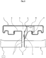
- Fig. 1 shows a support section 1 with two panels 2, 3 in the fully assembled state.
- the right panel 2 is equipped according to the invention with a folding hook 4.
- the support section 1 has on its underside the downwardly open hooking 5, the opening surface is bounded on both sides by a respective profile wall 6, which is hooked from the bottom of the support section 1 to the interior of the Einitatinut 5 and thus an upwardly open hook forms.
- the panels 2, 3 are typically made as a flat sheet cassette.
- the horizontal major surface is laterally bordered by side walls 7, 8, which are vertically upwards from the main surface.
- the two parallel to the support profile 1 side walls 7 are at least partially hook-shaped at its upper end to the main surface of the panel 2, 3, curved so that they form a downwardly open hook part 9.
- a panel 2, 3 hangs on support profiles 1, by each with a side wall 7 from below into the Ein rehabilitationnut 5 of the longitudinal direction of this side wall parallel support profile 1 projects and with the open hook part 9 one of the two by a profile wall 6 to the center of the Ein vonnut 5 limited upwardly open hook of the support profile 1 includes.
- a respective Abklapphaken 4 is attached in each case close to a front end of the side wall 7. With regard to the longitudinal direction of the support profile 1, these two Abklapphaken 4 are at the same height.
- the Abklapphaken 4 can - as shown - be an approximately J-shaped bent sheet metal part. With the end of the longitudinal part 11 facing away from the curvature region 10, the folding hook 4 is connected to the side wall 7 of the panel 2.
- the longitudinal part 11 of the Abklapphakens 4 extends approximately parallel to the plane of the side wall 7 and slightly increases from the connection point with the side wall 7 of the main surface of the panel, so that the curvature region 10 from above the profile wall 6 on the support section 1 surrounds.
- the Abklapphaken 4 projects beyond the longitudinal end of the panel 2 addition.
- the folding hook on the panel 2 to which it is attached completely or almost completely rigid - so not pivotal - are held. This is the mounting and unmounting of the panel 2 on the support section 2 and the folding and unfolding for the person acting very simple. It is therefore also ensured that the folding hooks 4 are not accidentally unhooked from the support section 1 when handling the panel 2.
- a recess 12 is formed.
- This recess 12 is at least as long as the Abklapphaken 4 projects from the panel 2, the panel 3 in the horizontal direction. Through this recess 12 are Collisions between the panel 3 and the folding hook 4 of the adjacent panel 2 avoided.
- the recess 12 could be made smaller.
- the recess could also be completely omitted if the folding hook would not be arranged as outlined on the inside of the side wall 7 of the respective panel, but on the outside and if one would take a higher height of the ceiling in purchasing.
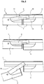
- Fig. 2 According to the middle picture of Fig. 2 is the panel 2 so far raised relative to the support section 1, that the direct entanglement between the panel 2 and support section 1 is detachable by the panel 2 is moved laterally relative to the support section 1.
- the Abklapphaken 4 lies on the support profile approximately both on the overhead surface, as well as on the upper surface of the profile wall 6.
- the folding hook 4 is still hooked to the profile wall 6, because the middle part of its curvature region 10, - Fig. 1 recognizable - compared to that area which is located behind the profile wall 6, is slimmer.
- the Abklapphakens 4 Due to this design of the Abklapphakens 4 is the folding hook 4 during all relative movement of the panel 2 when transferring from the folded state to the fully suspended state ( Fig. 2 top picture) and vice versa, always hooked securely with the profile wall 6 of the support section 1. In the unfolded state, the panel 2 is held exclusively in that it depends on two support hooks 4 on two support sections 1.
- the folding hook 4 abuts in the embodiment shown in the finished hinged panel 2 almost at the overhead base of the support section 1 (upper figure of Fig. 2 ) and because the panel 2 for mounting and unmounting on the support section 1 with respect to this still something must be raised (middle figure of Fig. 2 ), the Abklapphaken 4 relative to the panel 2 must be at least so far pivotable that its free end relative to the panel 2 by that height difference is movable up and down, as the panel 2 must be raised relative to the support section 1 to be posted , To package and transport panels 2, it is advantageous to make the folding hooks 4 pivotally so far "downwards" into the parallel to the plane of the panel 2, that it does not protrude upwards from the panel 2 completely detached from the supporting profile.
- the folding hook 4 by pressure or train on the panel 2 is normal to its level very well pivoted in the required manner when it rests with its curvature region 10 while the support section 1 at its base or on the profile wall 6. It is not distracting but rather advantageous if the folding hook 4 is so firmly connected to the panel 2 - for example, riveted, - that relative pivotal movement between the panel 1 and folding hook 4 is only by overcoming noticeable friction vonstatten.
- Abklapphakens 4 are much narrower normal to the hook plane, for example by its curvature is formed by a bent wire in one plane, the Abklapphaken collides when lifting the panel 2 for hanging from the support section. 1 not so fast or possibly not at all with the overhead surface of the support section 1.
- the function required pivoting range of Abklapphakens relative to the support section 1 could thus be smaller or completely eliminated in extreme cases. However, some security against accidental disconnection during handling is lost.
Landscapes
- Engineering & Computer Science (AREA)
- Architecture (AREA)
- Physics & Mathematics (AREA)
- Electromagnetism (AREA)
- Civil Engineering (AREA)
- Structural Engineering (AREA)
- Finishing Walls (AREA)
Abstract
Description
- Die Erfindung betrifft ein Unterdecke, welche ein Tragprofil und daran eingehängte Paneele aufweist.
- Häufig werden Unterdecken gebildet, indem Tragprofile parallel zueinander in einem Abstand zueinander im Raum angeordnet werden und indem Paneele an jeweils zwei benachbarten Tragprofilen befestigt werden, sodass sie die Fläche zwischen den benachbarten Tragprofilen überbrücken. Die Tragprofile ihrerseits sind über eine Tragekonstruktion an der darüber befindlichen Rohdecke und/oder an seitlichen Raumwänden verankert. Sehr oft weisen die Tragprofile eine nach unten hin offene Nut auf, wobei die Profilwände, welche diese Nut seitlich begrenzen, im Bereich der Nutöffnung in Profilansicht hakenförmig zum Nutinneren hin gekrümmt sind. Die nach unten offene Nut wird oftmals - und ab nun auch in dieser Anmeldung - als "Einhängenut" bezeichnet. Die dazupassenden Paneele haben an zwei einander gegenüberliegenden Rändern nach oben hin ausgerichtete Seitenwände, welche zumindest abschnittsweise an ihrem oberen Endbereich in Profilansicht hakenartig Richtung Mitte der Paneelfläche hin gekrümmt sind. Zu ihrer Befestigung werden die Paneele an zwei zueinander benachbarten Tragprofilen so eingehängt, dass sich jeweils eine hakenartig gekrümmte Profilwand eines Tragprofils mit einer (in Profilansicht) hakenartig gekrümmten einfassenden Wand eines Paneels verhakt.
- In einer weit verbreiteten Ergänzung zu dem beschriebenen Bauprinzip einer Unterdecke, weisen die Paneele zwei separate, sogenannte Abklapphaken auf. Das sind Haken, welche gleichsinnig gekrümmt sind wie die seitlichen einfassenden Wände des Paneels und von diesen seitlichen Wänden aus etwas nach oben stehen. Die dauerhafte Haltefunktion für ein Paneel wird wie beschrieben durch direkte Verhakung zweier in Profilansicht hakenförmig gekrümmter, einfassender Wände des Paneels mit jeweils einer hakenförmig einwärts gekrümmten Nutflanke an einem Tragprofil bewerkstelligt. Für das temporäre Öffnen der Unterdecke wird diese Verhakung eines Paneels gelöst und das Paneel wird mit zwei Abklapphaken an zwei benachbarten Tragprofilen verankert, wobei das Paneel um die Verbindungslinie zwischen den beiden Abklapphaken schwenkbar ist. Die Bauweise ist hoch belastbar und damit auch für Paneele mit Deckenheizelementen oder Deckenkühlelementen anwendbar. Nachteilig ist, das die Bauweise relativ hoch aufträgt, weil die Abklapphaken immer von der Paneelebene aus vertikal nach oben stehen und daher bei montiertem Paneel weit über die Sichtebene der Paneele nach oben ragen und in der Einhängenut der Tragprofile Platz finden müssen.
- Gemäß den Schriften
AT 514809 B1 AT 515381 A2 - Der Erfinder hat sich die Aufgabe gestellt, Unterdecken aus aneinander verhakten Tragprofilen und Paneelen so mit Abklapphaken für Paneele auszubilden, dass eine flache Bauweise der Unterdecke möglich ist. Gegenüber der aus den Schriften
AT 514809 B1 AT 515381 A2 - Für das Lösen der Aufgabe wird wiederum davon ausgegangen, dass an den beiden zu den Tragprofilen parallelen Seitenwänden eines Paneels jeweils ein Abklapphaken befestigt ist, welcher mit jener hakenförmig gekrümmten Wand des Tragprofils verhakbar ist, mit welcher auch die betreffende Seitenwand des Paneels verhakbar ist.
- Als erfindungsgemäße Verbesserung dazu wird vorgeschlagen, den jeweiligen Abklapphaken gegenüber jener Seitenwand des Paneels, an welcher er befestigt ist, so ausgerichtet anzuordnen, dass er dauerhaft in, zur Ebene des Paneels paralleler Richtung (bei eingehängtem Paneel also horizontal) über die Stirnseite dieser Seitenwand vorragt. In einer besonders bevorzugten Ausführung ist zusätzlich jene Seitenwand des in Richtung der Tragprofile nächstfolgenden Paneels in jenem Längsbereich, über welchen sich der besagte Abklapphaken des benachbarten Paneels erstreckt, nicht mit einer Verhakung mit dem Tragprofil zu versehen.
- Die Erfindung wird an Hand von Zeichnungen zu einer beispielhaften erfindungsgemäßen Unterdecke veranschaulicht.
- Fig. 1:
- zeigt von einer Unterdecke in Teilschnittansicht ein Tragprofil und zwei darin eingehakte Paneele. Die Blickrichtung ist parallel zu dem Tragprofil; das rechts dargestellte Paneel ist erfindungsgemäß mit einem Abklapphaken ausgestattet, welcher vom Paneel aus zum Betrachter hin ab steht.
- Fig. 2:
- veranschaulicht an der Unterdecke von
Fig. 1 an Hand von drei Einzelbildern eine Abfolge der Bewegung eines erfindungsgemäß mit Abklapphaken versehen Paneels gegenüber einem Tragprofil beim Abklappen bzw. Hochklappen. Die Blickrichtung ist horizontal, normal zur Profilrichtung des Tragprofils. -
Fig. 1 zeigt ein Tragprofil 1 mit zwei Paneelen 2, 3 in fertig montiertem Zustand. Das rechte Paneel 2 ist erfindungsgemäß mit einem Abklapphaken 4 ausgestattet. - Das Tragprofil 1 weist an seiner Unterseite die nach unten offene Einhängenut 5 auf, deren Öffnungsfläche an beiden Seiten durch jeweils eine Profilwand 6 begrenzt ist, welche von der Unterseite des Tragprofils 1 zum Inneren der Einhängenut 5 hakenartig eingekrümmt ist und somit einen nach oben offenen Haken bildet.
- Die Paneele 2, 3 sind typischerweise als flache Blechkassette gefertigt. Die horizontale Hauptfläche ist seitlich durch Seitenwände 7, 8, welche von der Hauptfläche aus vertikal nach oben stehen, eingefasst. Die beiden zum Tragprofil 1 parallel ausgerichteten Seitenwände 7 sind an ihrem freien oberen Ende zumindest abschnittsweise hakenartig zur Hauptfläche des Paneels 2, 3 hin gekrümmt, sodass sie einen nach unten offenen Hakenteil 9 bilden.
- In fertig montiertem Zustand hängt ein Paneel 2, 3 an Tragprofilen 1, indem es mit jeweils einer Seitenwand 7 von unten her in die Einhängenut 5 des zur Längsrichtung dieser Seitenwand parallel verlaufenden Tragprofils 1 ragt und mit dem offenen Hakenteil 9 einen der beiden durch eine Profilwand 6 zur Mitte der Einhängenut 5 hin begrenzten nach oben offenen Haken des Tragprofils 1 umfasst. Die beiden spiegelbildlich gegenüberliegenden, zueinander parallelen Seitenwände 7 des Paneels 2, greifen dabei in jeweils eines von zwei benachbarten, zueinander parallelen Tragprofilen 1 ein.
- An jeder der beiden Seitenwände 7 des Paneels 2, welche zum Tragprofil 1 parallel ausgerichtet sind, ist jeweils nahe an einem stirnseitigen Ende der Seitenwand 7 jeweils ein Abklapphaken 4 befestigt. Bezüglich der Längsrichtung des Tragprofils 1 liegen diese beiden Abklapphaken 4 auf gleicher Höhe.
- Der Abklapphaken 4 kann - wie dargestellt - ein etwa J-förmig gebogener Blechteil sein. Mit dem vom Krümmungsbereich 10 abgewandt liegenden Ende des Längsteils 11 ist der Abklapphaken 4 mit der Seitenwand 7 des Paneels 2 verbunden.
- Wie insbesondere aus
Fig. 2 gut erkennbar, erstreckt sich der Längsteil 11 des Abklapphakens 4 etwa parallel zur Ebene der Seitenwand 7 und steigt vom Verbindungspunkt mit der Seitenwand 7 leicht von der Hauptfläche des Paneels weg an, sodass der Krümmungsbereich 10 von oben her die Profilwand 6 am Tragprofil 1 umgreift. - Von erfindungsgemäß wesentlicher Bedeutung ist, dass der Abklapphaken 4 über das Längsende des Paneels 2 hinaus ragt. Durch diese Maßnahme kann der Abklapphaken am Paneel 2 an welchem er befestigt ist, ganz oder annähernd ganz starr - also nicht schwenkbar - gehalten werden. Damit ist das Ein- und Aushängen des Paneels 2 am Tragprofil 2 sowie das Auf- und Abklappen für die handelnde Person sehr einfach. Es wird damit auch sicher erreicht, dass die Abklapphaken 4 beim Hantieren mit dem Paneel 2 nicht versehentlich vom Tragprofil 1 ausgehakt werden.
- Wie in
Fig. 2 gut erkennbar, ist am Paneel 3 der obere Teil des dem Paneel 2 zugewandten Längsbereichs der zum Tragprofil 1 parallel liegenden Seitenwand 7 entfernt, sodass eine Ausnehmung 12 gebildet ist. Diese Ausnehmung 12 ist mindestens so lang, wie der Abklapphaken 4 vom Paneel 2 das Paneel 3 in horizontaler Richtung überragt. Durch diese Ausnehmung 12 werden Kollisionen zwischen dem Paneel 3 und dem Abklapphaken 4 des benachbarten Paneels 2 vermieden. - Wenn anstatt eines relativ breiten Abklapphakens 4 aus Blech ein sehr schmaler Abklapphaken aus Draht verwendet werden würde, könnte die Ausnehmung 12 kleiner ausgebildet sein. Die Ausnehmung könnte auch ganz entfallen, wenn der Abklapphaken nicht wie skizziert an der Innenseite der Seitenwand 7 des jeweiligen Paneels angeordnet wäre, sondern an der Außenseite und wenn man eine höhere Bauhöhe der Unterdecke in Kauf nehmen würde.
- (Die zum Tragprofil normal liegenden Seitenwände 8 der Paneele sind am Eckbereich zu den Seitenwänden 7 ohnedies auch bei Bauweisen gemäß dem Stand der Technik mit Ausnehmungen zu versehen, da Paneele ansonsten gar nicht einhängbar wären.)
- Gemäß der mittleren Abbildung von
Fig. 2 ist das Paneel 2 gegenüber dem Tragprofil 1 so weit angehobenen, dass die direkte Verhakung zwischen Paneel 2 und Tragprofil 1 lösbar ist, indem das Paneel 2 gegenüber dem Tragprofil 1 seitlich verschoben wird. Der Abklapphaken 4 liegt dabei am Tragprofil annähernd sowohl an der oben liegenden Grundfläche an, als auch am obersten Flächenbereich der Profilwand 6. Der Abklapphaken 4 ist dabei dennoch noch mit der Profilwand 6 verhakt, weil der mittlere Teil seines Krümmungsbereichs 10, - wie inFig. 1 erkennbar - gegenüber jenem Bereich, welcher sich hinter der Profilwand 6 befindet, schlanker ausgebildet ist. - Durch diese Ausbildung des Abklapphakens 4 ist der Abklapphaken 4 während aller Relativbewegung die das Paneel 2 beim Überführen vom abgeklappten Zustand bis zum fertig eingehängten Zustand (
Fig. 2 oberste Abbildung) und umgekehrt durchläuft, immer sicher mit der Profilwand 6 des Tragprofils 1 verhakt. Im fertig abgeklappten Zustand ist das Paneel 2 ausschließlich dadurch gehalten, dass es über zwei Abklapphaken 4 an zwei Tragprofilen 1 hängt. - Da der Abklapphaken 4 bei der gezeigten Ausführung bei fertig eingehängtem Paneel 2 fast an der oben liegenden Grundfläche des Tragprofils 1 anliegt (obere Abbildung von
Fig. 2 ) und da das Paneel 2 zum Ein- und Aushängen am Tragprofil 1 gegenüber diesem noch etwas angehoben werden muss (mittlere Abbildung vonFig. 2 ), muss der Abklapphaken 4 gegenüber dem Paneel 2 zumindest so weit schwenkbar sein, dass sein freies Ende gegenüber dem Paneel 2 um jene Höhendifferenz auf- und ab bewegbar ist, wie das Paneel 2 gegenüber dem Tragprofil 1 angehoben werden muss um ausgehängt werden zu können. Um Verpackung und Transport von Paneelen 2 einfach zu halten ist es vorteilhaft den Abklapphaken 4 darüber hinaus so weit "nach unten" in die Parallele zur Ebene des Paneels 2 schwenkbar auszubilden, dass er bei vom Tragprofil vollständig gelöstem Paneel 2 von diesem nicht nach oben hin vorragt. - Indem bei all dieser erforderlichen Schwenkbarkeit des Abklapphakens 4 gegenüber dem Paneel 2 der Abklapphaken nie mehr als 20° aus der Parallelen zur Ebene des Paneels 2 weg geschwenkt ist, ist der Abklapphaken 4 durch Druck bzw. Zug am Paneel 2 normal zu dessen Ebene sehr gut in der erforderlichen Weise schwenkbar, wenn er mit seinem Krümmungsbereich 10 dabei am Tragprofil 1 an dessen Grundfläche bzw. an dessen Profilwand 6 anliegt. Dabei ist es keineswegs störend sondern eher vorteilhaft, wenn der Abklapphaken 4 so fest mit dem Paneel 2 verbunden ist- beispielsweise vernietet ist, - dass relative Schwenkbewegung zwischen Paneel 1 und Abklapphaken 4 nur unter Überwindung von deutlich spürbarer Reibung vonstatten geht.
- Wenn an Stelle des skizzierten Abklapphakens 4 ein solcher verwendet werden würde, welcher normal zur Hakenebene deutlich schmäler ist, beispielsweise indem sein Krümmungsbereich durch einen nur in einer Ebene gebogenen Draht gebildet ist, kollidiert der Abklapphaken beim Anheben des Paneels 2 zum Aushängen aus dem Tragprofil 1 nicht so schnell oder evtl. gar nicht mit der oben liegenden Grundfläche des Tragprofils 1. Der funktionserforderliche Schwenkbereich des Abklapphakens gegenüber dem Tragprofil 1 könnte damit kleiner sein oder im Extremfall ganz wegfallen. Allerdings geht dabei etwas Sicherheit gegen versehentliches Aushängen während des Hantierens verloren.
Claims (4)
- Unterdecke, welche parallel und in einem Abstand zueinander angeordnete Tragprofile (1) aufweist, sowie Paneele (2, 3), welche an jeweils zwei benachbarten Tragprofilen (1) befestigt sind, wobei ein Tragprofil (1) eine nach unten hin offene Einhängenut (5) aufweist, wobei jeweils eine Profilwand (6) die Einhängenut (5) seitlich begrenzt, indem die Profilwand (6) im Bereich der Nutöffnung nach oben zum Nutinneren hin gekrümmt ist, wobei ein Paneel (2, 3) an zwei einander gegenüberliegenden Rändern jeweils eine sich von der Hauptfläche des Paneels (2, 3) aus nach oben hin erstreckende Seitenwand (7) aufweist, welche an ihrem oberen Endbereich erst auf die Mitte der Paneelfläche zu und dann nach unten gekrümmt ist und mit diesem zu einem Haken (9) gekrümmten Bereich von der Einhängenut (5) des Tragprofils (1) die Profilwand (6) des Tragprofils (1) oben umgreift, wobei an den beiden Seitenwänden (7) eines Paneels (2) jeweils im Naheberich zu einem stirnseitigen Ende der jeweiligen Seitenwand (7) jeweils ein Abklapphaken (4) befestigt ist, welcher mit seinem hakenförmig gekrümmten Bereich (10) ebenfalls von der Einhängenut (5) des Tragprofils (1) die Profilwand (6) des Tragprofils (1) oben umgreift und wobei das an dem stirnseitigen Ende der Seitenwand (7) in Richtung des Tragprofils (1) nächstfolgende Paneel (3) an der dem Paneel (2) zugewandten Seite nicht mit Abklapphaken versehen ist,
dadurch gekennzeichnet, dass
der Abklapphaken (4) in zur Paneelebene paralleler Richtung dauerhaft über jenes stirnseitige Ende der Seitenwand (7) des Paneels (2) in dessen Nahbereich er befestigt ist, hinaus ragt, sodass sich sein hakenförmig gekrümmten Bereich (10) oberhalb der Hauptfläche des dem Paneel (2) in Profilrichtung des Tragprofils (1) nächstfolgenden Paneels (3) befindet. - Unterdecke nach Anspruch 1, dadurch gekennzeichnet, dass sich an der Seitenwand (7) des auf das Paneel (2) nächstfolgenden Paneels (3) in jenem Längsbereich, in welchen der Abklapphaken (4) vom ersten Paneel (2) aus ragt, kein Haken (9) befindet.
- Unterdecke nach Anspruch 2, dadurch gekennzeichnet, dass die Seitenwand (7) des auf das Paneel (2) nächstfolgenden Paneels (3) in jenem Längsbereich, in welchen der Abklapphaken (4) vom ersten Paneel (2) aus ragt, im oberen Bereich entfernt ist, sodass damit eine Ausnehmung (12) gebildet ist.
- Unterdecke nach einem der Ansprüche 1 bis 3, dadurch gekennzeichnet, dass der Abklapphaken (4) im mittleren Bereich des Krümmungsbereiches (10) in der zur Hakenebene normalen Richtung schmäler ist, als an jenem Bereich, welcher bei mit dem Tragprofil (1) verhaktem Klapphaken (1) von der Mitte der Einhängenut (5) aus gesehen, hinter jener Profilwand (6) liegt, welche die Einhängenut (5) seitlich begrenzt.
Applications Claiming Priority (1)
| Application Number | Priority Date | Filing Date | Title |
|---|---|---|---|
| AT962016 | 2016-02-25 |
Publications (3)
| Publication Number | Publication Date |
|---|---|
| EP3211149A1 true EP3211149A1 (de) | 2017-08-30 |
| EP3211149B1 EP3211149B1 (de) | 2021-05-05 |
| EP3211149B8 EP3211149B8 (de) | 2021-06-16 |
Family
ID=58645087
Family Applications (1)
| Application Number | Title | Priority Date | Filing Date |
|---|---|---|---|
| EP17000287.7A Active EP3211149B8 (de) | 2016-02-25 | 2017-02-23 | Unterdecke, welche ein trageprofil und daran eingehängte paneele aufweist |
Country Status (1)
| Country | Link |
|---|---|
| EP (1) | EP3211149B8 (de) |
Citations (3)
| Publication number | Priority date | Publication date | Assignee | Title |
|---|---|---|---|---|
| DE1962581A1 (de) * | 1969-12-13 | 1971-06-24 | Schmitt Hans Julius | Montagedecke aus einzelnen Blechkassetten zur Befestigung an einem aus Klemmschienen gebildeten und an der Rohdecke abgehaengten Tragerost |
| EP1209296A1 (de) * | 2000-11-22 | 2002-05-29 | USG INTERIORS, Inc. | Schwenkbares Deckenpaneel |
| AT514809B1 (de) | 2014-01-15 | 2015-04-15 | Robert Peer | Unterdecke, welche ein Trageprofil und daran eingehängte Paneele aufweist |
-
2017
- 2017-02-23 EP EP17000287.7A patent/EP3211149B8/de active Active
Patent Citations (4)
| Publication number | Priority date | Publication date | Assignee | Title |
|---|---|---|---|---|
| DE1962581A1 (de) * | 1969-12-13 | 1971-06-24 | Schmitt Hans Julius | Montagedecke aus einzelnen Blechkassetten zur Befestigung an einem aus Klemmschienen gebildeten und an der Rohdecke abgehaengten Tragerost |
| EP1209296A1 (de) * | 2000-11-22 | 2002-05-29 | USG INTERIORS, Inc. | Schwenkbares Deckenpaneel |
| AT514809B1 (de) | 2014-01-15 | 2015-04-15 | Robert Peer | Unterdecke, welche ein Trageprofil und daran eingehängte Paneele aufweist |
| AT515381A2 (de) | 2014-01-15 | 2015-08-15 | Robert Peer | Unterdecke, welche ein Trageprofil und daran eingehängte Paneele aufweist |
Also Published As
| Publication number | Publication date |
|---|---|
| EP3211149B8 (de) | 2021-06-16 |
| EP3211149B1 (de) | 2021-05-05 |
Similar Documents
| Publication | Publication Date | Title |
|---|---|---|
| EP0211172B1 (de) | Unterdecke | |
| AT515381B1 (de) | Unterdecke, welche ein Trageprofil und daran eingehängte Paneele aufweist | |
| DE102010010249B4 (de) | Solarmodulanordnung | |
| DE1261299B (de) | Versetzbare Trennwand | |
| DE102008047315A1 (de) | Haltevorrichtung mit einer Trägerplatte zur Aufnahme von Traggliedern | |
| DE8008759U1 (de) | Haenger fuer eine tragschiene einer unterdecke | |
| DE3526740C1 (de) | Gitterartige Unterdecke | |
| EP3211149B1 (de) | Unterdecke, welche ein trageprofil und daran eingehängte paneele aufweist | |
| DE102013108539A1 (de) | Verbindung und Verriegelungselement | |
| EP2324732A1 (de) | Lagerregal, insbesondere automatisches Kleinteilelager | |
| EP2348165A2 (de) | Lösbare Verriegelungsvorrichtung für Deckenelemente | |
| EP2578772A2 (de) | Klappbare Gerüstbodenerweiterung | |
| DE10044969A1 (de) | Wandprofilleiste | |
| CH657405A5 (de) | Montage-unterdecke. | |
| DE202005012080U1 (de) | Tragarm zum ausklinkbaren Eingriff in Paneelelementprofilschienen | |
| DE3804566C2 (de) | ||
| EP0448846A1 (de) | Unterdecke | |
| EP0049433B1 (de) | Rasterdecke | |
| DE220684C (de) | ||
| DE3038022C2 (de) | Aufhängbare Rasterdecke | |
| EP2907763B1 (de) | Wandverkleidung mit Drahtgitterkörben sowie Drahtgitterkorb | |
| DE912143C (de) | Haltevorrichtung fuer eine Heizkoerperverkleidung od. dgl. | |
| DE1931210C (de) | Hangedecke | |
| AT513926A1 (de) | Duschabtrennung | |
| DE202004003913U1 (de) | Regalsystem |
Legal Events
| Date | Code | Title | Description |
|---|---|---|---|
| PUAI | Public reference made under article 153(3) epc to a published international application that has entered the european phase |
Free format text: ORIGINAL CODE: 0009012 |
|
| STAA | Information on the status of an ep patent application or granted ep patent |
Free format text: STATUS: THE APPLICATION HAS BEEN PUBLISHED |
|
| AK | Designated contracting states |
Kind code of ref document: A1 Designated state(s): AL AT BE BG CH CY CZ DE DK EE ES FI FR GB GR HR HU IE IS IT LI LT LU LV MC MK MT NL NO PL PT RO RS SE SI SK SM TR |
|
| AX | Request for extension of the european patent |
Extension state: BA ME |
|
| STAA | Information on the status of an ep patent application or granted ep patent |
Free format text: STATUS: REQUEST FOR EXAMINATION WAS MADE |
|
| 17P | Request for examination filed |
Effective date: 20180223 |
|
| RBV | Designated contracting states (corrected) |
Designated state(s): AL AT BE BG CH CY CZ DE DK EE ES FI FR GB GR HR HU IE IS IT LI LT LU LV MC MK MT NL NO PL PT RO RS SE SI SK SM TR |
|
| STAA | Information on the status of an ep patent application or granted ep patent |
Free format text: STATUS: EXAMINATION IS IN PROGRESS |
|
| 17Q | First examination report despatched |
Effective date: 20200313 |
|
| GRAP | Despatch of communication of intention to grant a patent |
Free format text: ORIGINAL CODE: EPIDOSNIGR1 |
|
| STAA | Information on the status of an ep patent application or granted ep patent |
Free format text: STATUS: GRANT OF PATENT IS INTENDED |
|
| INTG | Intention to grant announced |
Effective date: 20201208 |
|
| GRAS | Grant fee paid |
Free format text: ORIGINAL CODE: EPIDOSNIGR3 |
|
| GRAA | (expected) grant |
Free format text: ORIGINAL CODE: 0009210 |
|
| STAA | Information on the status of an ep patent application or granted ep patent |
Free format text: STATUS: THE PATENT HAS BEEN GRANTED |
|
| AK | Designated contracting states |
Kind code of ref document: B1 Designated state(s): AL AT BE BG CH CY CZ DE DK EE ES FI FR GB GR HR HU IE IS IT LI LT LU LV MC MK MT NL NO PL PT RO RS SE SI SK SM TR |
|
| REG | Reference to a national code |
Ref country code: GB Ref legal event code: FG4D Free format text: NOT ENGLISH |
|
| REG | Reference to a national code |
Ref country code: CH Ref legal event code: EP |
|
| REG | Reference to a national code |
Ref country code: AT Ref legal event code: REF Ref document number: 1389981 Country of ref document: AT Kind code of ref document: T Effective date: 20210515 |
|
| REG | Reference to a national code |
Ref country code: DE Ref legal event code: R096 Ref document number: 502017010244 Country of ref document: DE |
|
| REG | Reference to a national code |
Ref country code: IE Ref legal event code: FG4D Free format text: LANGUAGE OF EP DOCUMENT: GERMAN |
|
| REG | Reference to a national code |
Ref country code: CH Ref legal event code: PK Free format text: BERICHTIGUNGEN Ref country code: CH Ref legal event code: PK Free format text: BERICHTIGUNG B8 |
|
| RAP2 | Party data changed (patent owner data changed or rights of a patent transferred) |
Owner name: BAUSTOFF + METALL GMBH |
|
| RIN2 | Information on inventor provided after grant (corrected) |
Inventor name: PEER, ROBERT |
|
| REG | Reference to a national code |
Ref country code: LT Ref legal event code: MG9D |
|
| PG25 | Lapsed in a contracting state [announced via postgrant information from national office to epo] |
Ref country code: BG Free format text: LAPSE BECAUSE OF FAILURE TO SUBMIT A TRANSLATION OF THE DESCRIPTION OR TO PAY THE FEE WITHIN THE PRESCRIBED TIME-LIMIT Effective date: 20210805 Ref country code: HR Free format text: LAPSE BECAUSE OF FAILURE TO SUBMIT A TRANSLATION OF THE DESCRIPTION OR TO PAY THE FEE WITHIN THE PRESCRIBED TIME-LIMIT Effective date: 20210505 Ref country code: LT Free format text: LAPSE BECAUSE OF FAILURE TO SUBMIT A TRANSLATION OF THE DESCRIPTION OR TO PAY THE FEE WITHIN THE PRESCRIBED TIME-LIMIT Effective date: 20210505 Ref country code: FI Free format text: LAPSE BECAUSE OF FAILURE TO SUBMIT A TRANSLATION OF THE DESCRIPTION OR TO PAY THE FEE WITHIN THE PRESCRIBED TIME-LIMIT Effective date: 20210505 |
|
| PG25 | Lapsed in a contracting state [announced via postgrant information from national office to epo] |
Ref country code: PL Free format text: LAPSE BECAUSE OF FAILURE TO SUBMIT A TRANSLATION OF THE DESCRIPTION OR TO PAY THE FEE WITHIN THE PRESCRIBED TIME-LIMIT Effective date: 20210505 Ref country code: NO Free format text: LAPSE BECAUSE OF FAILURE TO SUBMIT A TRANSLATION OF THE DESCRIPTION OR TO PAY THE FEE WITHIN THE PRESCRIBED TIME-LIMIT Effective date: 20210805 Ref country code: PT Free format text: LAPSE BECAUSE OF FAILURE TO SUBMIT A TRANSLATION OF THE DESCRIPTION OR TO PAY THE FEE WITHIN THE PRESCRIBED TIME-LIMIT Effective date: 20210906 Ref country code: RS Free format text: LAPSE BECAUSE OF FAILURE TO SUBMIT A TRANSLATION OF THE DESCRIPTION OR TO PAY THE FEE WITHIN THE PRESCRIBED TIME-LIMIT Effective date: 20210505 Ref country code: SE Free format text: LAPSE BECAUSE OF FAILURE TO SUBMIT A TRANSLATION OF THE DESCRIPTION OR TO PAY THE FEE WITHIN THE PRESCRIBED TIME-LIMIT Effective date: 20210505 Ref country code: IS Free format text: LAPSE BECAUSE OF FAILURE TO SUBMIT A TRANSLATION OF THE DESCRIPTION OR TO PAY THE FEE WITHIN THE PRESCRIBED TIME-LIMIT Effective date: 20210905 Ref country code: LV Free format text: LAPSE BECAUSE OF FAILURE TO SUBMIT A TRANSLATION OF THE DESCRIPTION OR TO PAY THE FEE WITHIN THE PRESCRIBED TIME-LIMIT Effective date: 20210505 Ref country code: GR Free format text: LAPSE BECAUSE OF FAILURE TO SUBMIT A TRANSLATION OF THE DESCRIPTION OR TO PAY THE FEE WITHIN THE PRESCRIBED TIME-LIMIT Effective date: 20210806 |
|
| REG | Reference to a national code |
Ref country code: NL Ref legal event code: MP Effective date: 20210505 |
|
| PG25 | Lapsed in a contracting state [announced via postgrant information from national office to epo] |
Ref country code: NL Free format text: LAPSE BECAUSE OF FAILURE TO SUBMIT A TRANSLATION OF THE DESCRIPTION OR TO PAY THE FEE WITHIN THE PRESCRIBED TIME-LIMIT Effective date: 20210505 |
|
| PG25 | Lapsed in a contracting state [announced via postgrant information from national office to epo] |
Ref country code: ES Free format text: LAPSE BECAUSE OF FAILURE TO SUBMIT A TRANSLATION OF THE DESCRIPTION OR TO PAY THE FEE WITHIN THE PRESCRIBED TIME-LIMIT Effective date: 20210505 Ref country code: RO Free format text: LAPSE BECAUSE OF FAILURE TO SUBMIT A TRANSLATION OF THE DESCRIPTION OR TO PAY THE FEE WITHIN THE PRESCRIBED TIME-LIMIT Effective date: 20210505 Ref country code: EE Free format text: LAPSE BECAUSE OF FAILURE TO SUBMIT A TRANSLATION OF THE DESCRIPTION OR TO PAY THE FEE WITHIN THE PRESCRIBED TIME-LIMIT Effective date: 20210505 Ref country code: DK Free format text: LAPSE BECAUSE OF FAILURE TO SUBMIT A TRANSLATION OF THE DESCRIPTION OR TO PAY THE FEE WITHIN THE PRESCRIBED TIME-LIMIT Effective date: 20210505 Ref country code: CZ Free format text: LAPSE BECAUSE OF FAILURE TO SUBMIT A TRANSLATION OF THE DESCRIPTION OR TO PAY THE FEE WITHIN THE PRESCRIBED TIME-LIMIT Effective date: 20210505 Ref country code: SK Free format text: LAPSE BECAUSE OF FAILURE TO SUBMIT A TRANSLATION OF THE DESCRIPTION OR TO PAY THE FEE WITHIN THE PRESCRIBED TIME-LIMIT Effective date: 20210505 Ref country code: SM Free format text: LAPSE BECAUSE OF FAILURE TO SUBMIT A TRANSLATION OF THE DESCRIPTION OR TO PAY THE FEE WITHIN THE PRESCRIBED TIME-LIMIT Effective date: 20210505 |
|
| REG | Reference to a national code |
Ref country code: DE Ref legal event code: R097 Ref document number: 502017010244 Country of ref document: DE |
|
| PLBE | No opposition filed within time limit |
Free format text: ORIGINAL CODE: 0009261 |
|
| STAA | Information on the status of an ep patent application or granted ep patent |
Free format text: STATUS: NO OPPOSITION FILED WITHIN TIME LIMIT |
|
| 26N | No opposition filed |
Effective date: 20220208 |
|
| PG25 | Lapsed in a contracting state [announced via postgrant information from national office to epo] |
Ref country code: IS Free format text: LAPSE BECAUSE OF FAILURE TO SUBMIT A TRANSLATION OF THE DESCRIPTION OR TO PAY THE FEE WITHIN THE PRESCRIBED TIME-LIMIT Effective date: 20210905 Ref country code: AL Free format text: LAPSE BECAUSE OF FAILURE TO SUBMIT A TRANSLATION OF THE DESCRIPTION OR TO PAY THE FEE WITHIN THE PRESCRIBED TIME-LIMIT Effective date: 20210505 |
|
| PG25 | Lapsed in a contracting state [announced via postgrant information from national office to epo] |
Ref country code: IT Free format text: LAPSE BECAUSE OF FAILURE TO SUBMIT A TRANSLATION OF THE DESCRIPTION OR TO PAY THE FEE WITHIN THE PRESCRIBED TIME-LIMIT Effective date: 20210505 |
|
| PG25 | Lapsed in a contracting state [announced via postgrant information from national office to epo] |
Ref country code: MC Free format text: LAPSE BECAUSE OF FAILURE TO SUBMIT A TRANSLATION OF THE DESCRIPTION OR TO PAY THE FEE WITHIN THE PRESCRIBED TIME-LIMIT Effective date: 20210505 |
|
| REG | Reference to a national code |
Ref country code: BE Ref legal event code: MM Effective date: 20220228 |
|
| GBPC | Gb: european patent ceased through non-payment of renewal fee |
Effective date: 20220223 |
|
| PG25 | Lapsed in a contracting state [announced via postgrant information from national office to epo] |
Ref country code: LU Free format text: LAPSE BECAUSE OF NON-PAYMENT OF DUE FEES Effective date: 20220223 |
|
| PG25 | Lapsed in a contracting state [announced via postgrant information from national office to epo] |
Ref country code: FR Free format text: LAPSE BECAUSE OF NON-PAYMENT OF DUE FEES Effective date: 20220228 |
|
| PG25 | Lapsed in a contracting state [announced via postgrant information from national office to epo] |
Ref country code: IE Free format text: LAPSE BECAUSE OF NON-PAYMENT OF DUE FEES Effective date: 20220223 Ref country code: GB Free format text: LAPSE BECAUSE OF NON-PAYMENT OF DUE FEES Effective date: 20220223 |
|
| PG25 | Lapsed in a contracting state [announced via postgrant information from national office to epo] |
Ref country code: BE Free format text: LAPSE BECAUSE OF NON-PAYMENT OF DUE FEES Effective date: 20220228 |
|
| PG25 | Lapsed in a contracting state [announced via postgrant information from national office to epo] |
Ref country code: HU Free format text: LAPSE BECAUSE OF FAILURE TO SUBMIT A TRANSLATION OF THE DESCRIPTION OR TO PAY THE FEE WITHIN THE PRESCRIBED TIME-LIMIT; INVALID AB INITIO Effective date: 20170223 |
|
| PG25 | Lapsed in a contracting state [announced via postgrant information from national office to epo] |
Ref country code: MK Free format text: LAPSE BECAUSE OF FAILURE TO SUBMIT A TRANSLATION OF THE DESCRIPTION OR TO PAY THE FEE WITHIN THE PRESCRIBED TIME-LIMIT Effective date: 20210505 Ref country code: CY Free format text: LAPSE BECAUSE OF FAILURE TO SUBMIT A TRANSLATION OF THE DESCRIPTION OR TO PAY THE FEE WITHIN THE PRESCRIBED TIME-LIMIT Effective date: 20210505 |
|
| PG25 | Lapsed in a contracting state [announced via postgrant information from national office to epo] |
Ref country code: TR Free format text: LAPSE BECAUSE OF FAILURE TO SUBMIT A TRANSLATION OF THE DESCRIPTION OR TO PAY THE FEE WITHIN THE PRESCRIBED TIME-LIMIT Effective date: 20210505 |
|
| PG25 | Lapsed in a contracting state [announced via postgrant information from national office to epo] |
Ref country code: MT Free format text: LAPSE BECAUSE OF FAILURE TO SUBMIT A TRANSLATION OF THE DESCRIPTION OR TO PAY THE FEE WITHIN THE PRESCRIBED TIME-LIMIT Effective date: 20210505 |
|
| REG | Reference to a national code |
Ref country code: CH Ref legal event code: U11 Free format text: ST27 STATUS EVENT CODE: U-0-0-U10-U11 (AS PROVIDED BY THE NATIONAL OFFICE) Effective date: 20260301 |
|
| PGFP | Annual fee paid to national office [announced via postgrant information from national office to epo] |
Ref country code: DE Payment date: 20260219 Year of fee payment: 10 |
|
| PGFP | Annual fee paid to national office [announced via postgrant information from national office to epo] |
Ref country code: AT Payment date: 20260223 Year of fee payment: 10 |
|
| PGFP | Annual fee paid to national office [announced via postgrant information from national office to epo] |
Ref country code: CH Payment date: 20260301 Year of fee payment: 10 |