EP3212864B1 - Vorzelt für eine campingunterkunft - Google Patents
Vorzelt für eine campingunterkunft Download PDFInfo
- Publication number
- EP3212864B1 EP3212864B1 EP14802315.3A EP14802315A EP3212864B1 EP 3212864 B1 EP3212864 B1 EP 3212864B1 EP 14802315 A EP14802315 A EP 14802315A EP 3212864 B1 EP3212864 B1 EP 3212864B1
- Authority
- EP
- European Patent Office
- Prior art keywords
- awning
- awning according
- airbag
- tent
- region
- Prior art date
- Legal status (The legal status is an assumption and is not a legal conclusion. Google has not performed a legal analysis and makes no representation as to the accuracy of the status listed.)
- Active
Links
Images




Classifications
-
- E—FIXED CONSTRUCTIONS
- E04—BUILDING
- E04H—BUILDINGS OR LIKE STRUCTURES FOR PARTICULAR PURPOSES; SWIMMING OR SPLASH BATHS OR POOLS; MASTS; FENCING; TENTS OR CANOPIES, IN GENERAL
- E04H15/00—Tents or canopies, in general
- E04H15/20—Tents or canopies, in general inflatable, e.g. shaped, strengthened or supported by fluid pressure
- E04H15/22—Tents or canopies, in general inflatable, e.g. shaped, strengthened or supported by fluid pressure supported by air pressure inside the tent
-
- E—FIXED CONSTRUCTIONS
- E04—BUILDING
- E04H—BUILDINGS OR LIKE STRUCTURES FOR PARTICULAR PURPOSES; SWIMMING OR SPLASH BATHS OR POOLS; MASTS; FENCING; TENTS OR CANOPIES, IN GENERAL
- E04H15/00—Tents or canopies, in general
- E04H15/02—Tents combined or specially associated with other devices
- E04H15/06—Tents at least partially supported by vehicles
- E04H15/08—Trailer awnings or the like
Definitions
- the invention relates to an awning for a camping accommodation in the form of a camping trailer, a caravan, a mobile home or the like. Vehicle usable during camping according to the preamble of claim 1.
- a scaffold can be constructed from respective profile strips to form a system composed of horizontal and vertical sections.
- Special air chamber elements are then to be inserted into the free spaces of this scaffold in the area between the respective profile rails, so that a largely closed interior can be formed.
- These air chamber elements must also be fixed to the caravan piping strips, so that the kit is connected to the camping accommodation.
- the one-piece air chamber elements are to be transported as individual parts to the installation site, so that a comparatively high amount of transport is required while at the same time requiring a large amount of space. Fixing the individual elements of the scaffolding and attaching the air chamber elements are complex.
- a construction that can be fixed on the vehicle wall in a conventional design which forms an air-permeable zone between the wall-side or ceiling-side tent sheets.
- An air-permeable additional part is to be inserted into the space when the scaffold is erected.
- the linkage must first be erected from the respective strut parts in a conventional design, and then the at least partially double-layer tent sheet construction can be connected to the support elements. Complex building instructions must be followed in this process so that long-term assembly or disassembly can be accomplished by inexperienced users.
- each additional subassembly forming an awning is already integrated in the camping vehicle.
- An additional usable space is formed by appropriate opening movements in the area of the vehicle ( US 4,113,301 ; US 5,080,426 ; US 5,419,607 ).
- respective inflatable systems are provided on the vehicle. These vehicles then form an integrated system that can be used as a camping vehicle ( US 4,093,302 ; US 4,296,960 ; US 5,692,795 ; US 201010230999 A1 ).
- Variable designs of tent constructions are also known, in particular for commercial purposes, in which an inflation process is provided to create a usable space WO 03/006765 A1 becomes a permanent stabilization of an inflatable marquee or similar canopy with the folded tent sheet hinged linkage provided.
- This construction is complex, so that the components of this system can only be moved to their destination by transport by truck. After erecting the system, this requires additional assistants when disassembling.
- Inflatable tubes are used for simpler tent systems ( US 5,987,822 ; US 6,263,617 B1 ; US 6,810,896 B2 ; DE 92 01 195 U1 ; FR 2 845 412 ; DE 76 02 841 U1 ), so that different transportable tent constructions can be used as a self-sufficient unit. However, these cannot be connected to a camping accommodation as an awning.
- Modular tent systems are also known, in which air chambers replace the function of a tent pole ( DE 203 05 372 U1 ; DE 201 14 974 U1 ; GB 2 378 925 B ).
- Out DE 90 01 184 U1 a multi-purpose tent is known, the inner bottom of which is designed as an inflatable floor spacer.
- a camping vehicle with an inflatable tent construction is known, a base tent with an assembly intended as an early part forming a complex usable system in a transportable trailer.
- the invention is concerned with the problem of designing an awning for a caravan or similar camping accommodation in such a way that this awning can be used as a self-sufficient unit, is easier to set up and dismantle together with inner pole parts, and is therefore more user-friendly User is reached.
- the awnings for caravans, mobile homes or the like which are known in different versions, have respective tent and wall sections in the use position, which are underpinned by a linkage that excites the system.
- a major problem when using awnings of this type is the complex process involved in the construction of these awnings in known constructions.
- the basic concept of the concept according to the invention is based on the fact that the awning is formed from an envelope construction that can be closed at least in the area of the respective flat side, roof and floor wall parts, so that this envelope construction can be inflated in an at least regionally airtight manner. If the "automatic" assembly process is continued, the uprighting envelope construction is more easily accessible, and parts of the linkage can be brought into the stiffening position with little effort.
- the envelope construction in the area of at least one of its flat side wall parts is provided with a connection unit which can be attached to a support wall or the like counterpart of the camping accommodation.
- This connection unit is designed in such a way that the essentially closed envelope construction can be moved, even in an at least partially inflated state, into the vicinity of the camping accommodation and here, in the area of the connection unit, respective counterparts - for example on the outer wall of the camping accommodation - for "docking" of the awning or the envelope construction can be used.
- connection unit is fixed in the area of an outer wall of the camping accommodation provided as the supporting wall, a known piping assembly being used here.
- the connection unit is designed overall as a tent web strip which can be provided in a variable width, so that an optimal connection with the respective counterpart in the area of the camping accommodation can be established in accordance with the respective frontal contour on the envelope construction.
- the integration of the tent strip forming the connection unit is designed so that the tent strip is held on the one hand with a first molded piping or similar releasable counterholder on the camping accommodation and on the other hand the detachable connection of the tent strip to the wall part of the awning by means of a second molded strip, a tear - And / or Velcro is produced. It goes without saying that respective parts of the linkage are easier to attach into the at least regionally inflated envelope structure or on at least one outside of this envelope structure and that the rod-envelope system can be completely erected if the inflation process is continued.
- the awning concept provides that the envelope construction with the pole parts is prepared as a largely pre-assembled unit and that the inflation volume in the area of the envelope construction, which is provided as an auxiliary method, increases the filling volume or the internal pressure to such an extent that the pole parts also in one optimal uprighting movement. This process can largely be continued automatically until the entire casing-linkage unit can be detected in the inflated state and can be moved independently. This makes it clear that the awning, as an inflated envelope construction, can be handled as a free-standing unit next to the camping accommodation.
- the technical implementation advantageously provides that the individual components in the form of the tent sheets and respective light metal rod parts have a weight suitable for handling.
- the envelope construction braced with at least partial struts of the linkage forms a free-standing structural unit and, if need be, can remain in the intended use position as a "single tent" even without the "secondary" camping vehicle.
- This is of particular interest if the mobile home, the camping trailer or the like vehicle is intended for a different use regardless of the self-sufficient awning assembly. In this case, you can choose between The camper van and awning are disconnected and the vehicle can be moved. It goes without saying that the vehicle can then be connected to the awning again after returning to the installation site.
- the concept of the awning provides that the cover structure can also be partially inflated when closed. Thereafter, at least respective partial struts of the rod can be introduced into this envelope construction in such a way that subsequent set-up movements and alignments of the awning are easier.
- the linkage can also be formed by respective stiffening elements integrated into the wall parts or the tent sheets, which already get into the intended position through the inflation process or can be optimally aligned by simple hand movements.
- the stiffening elements can be mutually supported in the area of the respective joints or the like in such a way that in these areas there is at least a phase of controlled movement when inflating and the intended position of use is thus largely achieved without additional manipulations.
- the associated linkage is provided with respective rod parts which can be inserted into the inflated envelope construction via an opening. These can be placed on the envelope construction using respective loops, Velcro fasteners or the like and fixed in a final installation position.
- a fluid-tight connection can preferably be established, so that - when using releasable connection members - an undesired entry of rainwater into the useful space area below the connection unit is avoided.
- this tent sheet strip provided as a connecting unit, an additional usable space is defined between the awning and the camping accommodation, which is covered at least on the upper side by the tent sheet strip, in the assembled use position of the system.
- the tent strip can be dimensioned in such a way that a closing contour that completely covers the usable space between the awning and the camping accommodation is defined.
- the web-shaped connection unit extends to the bottom wall part of the awning and that a closed connection is established here. This creates a space that is closed to the ground between the past and the camping accommodation.
- the tent sheet strip defining an additional useful space can also be designed with ventilation openings, so that optimal ventilation is possible in the area of this covering of the intermediate space and the discharge of water vapor can be regulated.
- the envelope construction in the area of the side wall part facing the camping accommodation is provided with a blower opening, so that preferably a blower provided with an electric drive in the area of the camping accommodation can be used.
- This blower can then, for example, bypass in the area of the connecting unit by means of an air guide hose or the like, so that the air can be introduced at largely any position of the envelope structure.
- a self-sufficient blower is used in the area of the blower opening, which blower can be connected to an external power supply, for example, independently of the mobile home or the camping accommodation.
- the construction of the inflatable awning - as a camping element that forms an additional usable space - can be adapted to different designs of poles.
- the envelope structure can be displaced in the region of a pivoting frame that is pivotally held on the camping accommodation, so that the inflation process provided in the region of the envelope structure can be initiated during or after pivoting away from a storage position. Only a few additional hand movements are required to fix the awning in the intended position of use.
- a further embodiment of the awning construction according to the invention provides that the envelope construction is integrated in the area of a motorhome, in the roof assembly of which.
- the envelope construction assumes a transport position from which the envelope construction can be moved when using an inflator that can be connected to the system.
- This inflation process can advantageously take place directly from the interior of the motorhome, so that in the Increasing air pressure building the roof area, the envelope construction is pivoted in a preferred lifting and extending direction.
- the intended installation position next to the motorhome is largely "automatically” achieved.
- the envelope construction can be moved together with one or more parts of the linkage and, during the inflation process, this structural unit is positioned in a position next to the motor home. The final position of use of the awning can then be achieved with just a few additional steps.
- a further embodiment of the awning according to the invention provides that the rod parts form a preassembled structural unit with the tent sheets, which can be designed in the usual manner at the installation site.
- a pressure body that can be filled with a fluid, at least in some areas, is now integrated into this expanded structural unit as an additional component.
- This pressure body component interacts with the rod parts and the at least one tent sheet as an easy-to-use functional unit.
- the novel pressure body is used as an erection or dismantling aid.
- the pressure body that can be filled with a fluid can be designed in different spatial configurations in such a way that the pressure body to be filled with the fluid at the place of use can optionally also interact with the structural unit inside or outside the tent sheets. In any case, it is achieved in a corresponding Filling phase of the pressure body a synchronous movement of tent sheets and rod parts can be realized and thus an "automatic" erection process takes place, the advantages of which are particularly obvious to older users.
- the concept of the pressure body can in particular be carried out in such a way that it is designed in the form of a single-layer or at least regionally double-walled hose or cushion element. This opens up the possibility of optionally filling the pressure body with liquid and / or air and thus realizing the intended erection or disassembly aid. This combination of effects differs significantly from the known "filling hoses", which are connected to a roof membrane instead of the stable tent poles.
- the pressure body is designed as an airbag which is comparatively simple and can be inserted into the structural unit from rod parts and tent sheets with little effort.
- This pressure body which is designed as an airbag, can in turn consist of sheet-like individual parts which can be transported in a space-saving manner and are connected at the place of use in an opening or closing area to form the closed airbag.
- a filling opening that can be connected to a pump system is provided on it. This filling opening can be designed as a permanently installed connecting piece.
- a connection zone can be provided in the area of respective opening or closing areas defined by pressure closures, a zipper or the like connector, so that a filling hose or the like connecting element can be inserted into the area in the area thereof Air bag can be inserted or connected to it in such a way that an excess pressure increasing its volume can be built up in the interior of the air bag. It is also conceivable to provide a pump located in the airbag so that the filling process takes place directly in the interior of the airbag.
- a further embodiment provides that the system can also be filled with a compressed gas from a pressure bottle, cartridge or the like, independently of a separate pump.
- a compressed gas from a pressure bottle, cartridge or the like.
- the use of industrial gases, CO 2 , helium or the like, non-flammable filling gases is conceivable.
- the inflating airbag as an assembly aid - whereby the upright airbag raises the pole parts close to their position of use and at the same time raises the tent web system located above the pole parts - the basic structure of the airbag, which is also "web-shaped" remain as an additional inner wall in the interior of the awning. It is conceivable to actuate at least one of the opening areas connecting the web-shaped individual parts of the airbag after inflation.
- the airbag can then be connected to the erected and stiffened rod parts as an inner wall - in the manner of a lining.
- the entire construction system of this multi-layer awning provides that the pressure body, which is designed in the form of the airbag, can already be partially covered with the preassembled pole parts in unfilled condition, the tent parts, which are at least partially unfolded, are positioned above these pole parts and then the airbag is filled by means of a in particular motor-operated air pump. After this filling process, an awning is set up, which can be handled as a self-sufficient unit "free-standing" with the inner rod parts and the air bag provided as the inner wall. In the usual installation position, this fully or partially erected self-sufficient unit is now moved to the area near the camping vehicle and the intended installation position of the awning is finally established here via a known perimeter connection.
- the inner airbag can be attached to the poles and / or the tent sheet using detachable connecting means.
- the awning is designed as a multi-layer tent sheet and that it interacts with the airbag forming the inner wall. This can in turn be composed of several wall parts in the area of its walls, so that air bags can be provided with correspondingly adaptable sizes for different types of tent and these can then be optimally converted as inner walls.
- the system of the inflatable airbag which is closed on the wall side, provides that at least one base wall part can be removable from it in the inflated state, so that the original structure of the airbag remains only as a partial area of the inner wall.
- the airbag is again composed completely of all wall parts in the area of its connection areas, the airbag is largely closed and then - by a corresponding pumping process - a slight excess pressure is generated in the interior.
- the rod parts can then be released from their stiffening position so that these parts rest "loosely” on the airbag.
- the air in the airbag can then be deflated. It is also conceivable to support this largely automatic folding process by means of an additional air extraction.
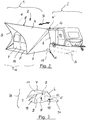
- FIG. 1 An awning, designated overall by 1, is shown in the area of a camping accommodation 2, which can be designed in the form of a camping trailer, a mobile home, a folding caravan or the like.
- the awning 1 connected to this device 2 is provided with respective wall parts 3, 4, 5, 6, 7 formed from tent sheets Z, and these are stiffened at least in regions by a linkage G in the use position.
- the awning 1 consists of an envelope structure H (at least in the area of the respective side, roof and floor wall parts 3, 4, 5, 6, 7) which can be inflated in an at least partially fluid-tight state.
- Fig. 3 is formed.
- This envelope structure H is designed in such a way that an autonomous movement of the system (arrow B, Fig. 2 ) is possible.
- the system of a "forced connection" of awning 1 and associated device 2 that was previously common on campsites is no longer provided according to the invention.
- the inflated envelope construction H can also be set up as a free-standing space next to the camping accommodation 2.
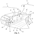
- a free-standing structural unit is formed in that the at least partial struts 8, 9 ( Fig. 4 ) of the frame G stiffened envelope construction H is fixed sufficiently stable.
- the envelope structure H is at least partially inflated in its closed state ( Fig. 3 ) and with the partial struts 8, 9 of the linkage G is braced at least in some areas.
- the linkage G is formed by respective stiffening elements (not shown) integrated into the wall parts or the tent sheets Z. The construction of such stiffening elements provides that they are moved at least in phases during inflation, automatically assume a fixing position, and thus an undesired collapse of the system (e.g. when the compressed air emerges from the interior) is avoided.
- the optimal design of the linkage G provides that it has rod parts 11, 12 () which can be inserted into the already partially inflated envelope structure H via an opening 10.
- Fig. 3 is provided (similar: partial struts 6, 7; Fig. 4 ). These can be moved during the inflation process (arrow E) (arrow F; Fig. 3 ).
- the envelope structure H is provided in the area of at least one of its flat side wall parts 6 with a connecting unit E, E 'which can be placed on a support wall 13 or the like. With this at least one connection unit E it is achieved that the substantially closed envelope structure H can be fixed in a connection position in an at least partially inflated state in the area of the camping accommodation 2.
- connection unit E or E ' is now used, which can optionally already be attached to the device 2 on a counter member 16 (E'; Fig. 2 ).
- the connecting unit E is fixed to the envelope structure H in a pre-assembly position (not shown) ( Fig. 4 , Fig. 5 ).
- connection unit E provides a fluid-tight design in the area between the counter member 16 and the connection unit E.
- 16 releasable connecting links are provided in the area of the envelope structure H or in the area of the counter link design provided on the camping accommodation 2.
- the representation according to Fig. 2 illustrates that, in the at least partially inflated state of the envelope structure H, the connecting unit E can be connected to an outer wall of the camping accommodation 2 provided as the supporting wall 13 by means of a piping assembly or the like.
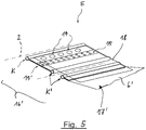
- a tent sheet strip 17 forming the connecting unit E can be fixed on the one hand to the camping accommodation 2 with a first molded piping K or the like.
- the releasable connection of the tent strip 17 to an extension 6 'of the wall part 6 of the awning 1 can be produced by means of a second welt K', a zipper and / or Velcro fastener.
- the preferred embodiment of the connecting unit E in the form of the tent sheet strip 17 enables an optimal connection of the components, the tent sheet strip 17 being adaptable to the frontal contour in the region of the wall 6 of the envelope structure H with little effort.
- a "premature extension" results with little effort, since the tent strip 17 in the area of the connection unit E in the position of use of the awning 1 between the tent and the camping accommodation 2 has a usable space which is at least covered on the upper side in accordance with distance dimension A '( Fig. 4 ) Are defined.
- the tent strip 17 has a closing contour which completely covers the useful space A 'between the awning 1 and the camping accommodation 2 (as in FIG Fig. 4 shown).
- This web-shaped connection unit E can be guided so far that a connection is also achieved in the area of the bottom wall part 5 of the awning 1.
- the tent sheet strip 17 ' illustrates in a conceivable double-layer version.
- respective ventilation openings 19 provided with a cover 18 are provided in the area of this tent strip 17 '.
- the envelope structure H can be provided with a blower opening 15, 15 'in the region of the side wall part 6 facing the camping accommodation 2.
- the blower 14, which can be connected to the envelope structure H, is provided in the area of the camping accommodation 2, and this has an air guide hose 15 ′ bridging the area of the connecting unit E.
- this "integrated" variant according to Fig. 4 shows the representation according to Fig. 3 the arrangement of the blower opening 15 in the area of an autonomous blower 14.
- FIG. 6 A further embodiment of the envelope structure H is shown, wherein it is displaceable (arrow D) and inflatable in the region of a pivoting frame 20 which is pivotally held on the camping accommodation 2. In the inflated state, this system is fixed in particular by respective bottom connectors 21.
- the above-described envelope structure H can be integrated in the area of a motorhome, a caravan or the like device 2, in particular in its roof assembly 22. From a transport position assumed in the process ( Fig. 7 ) the envelope structure H can be displaced or moved out by using an inflator 23 which is appropriately adapted to this starting position.
- the inflator 23 can be provided directly in the motor home 2 ( Fig. 7 ).
- an "external" inflator 23 ' can also be connected to the tent sheet Z in the region of an inlet opening 15' and the inflation process (arrow E) can be initiated.
- the linkage G of the envelope structure H is advantageously supported in a hinge-like manner in the region of connection points P, P 'on the roof 22 or lateral parts of the device 2 and pivoted in the direction S'. If the envelope structure H continues to fill - preferably with compressed air - at least the telescopic parts 24, 25, 26 of the respective support rods 27, 28 can be shifted or moved to the optimal support position, so that the tent poles G and "lightweight" tent sheets are largely automatic Z formed awning 1 is positioned in the use position.
- telescopic rods 29 and 30 can also be provided in the area of the linkage G.
- An upper support bracket 31 is advantageously provided in the vicinity of device 2 and associated wall area 6. This bracket 31 can also be designed with a U-shaped enlarged contour, so that in the position of use ( Fig. 8 ) an interior 32 in the roof area 22 of the motorhome 2 has an advantageous height W and an additional sleeping area or similar useful area is provided here.
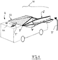
- Fig. 9 is a schematic representation of the process for a displacement or disassembly of the envelope structure H back to the transport position according to Fig. 7 clarifies.
- a suction process (arrow T ') generating a vacuum in the area of the opening 15' which acts as a suction opening in this phase
- the envelope structure H which can also be closed in the area of the floor mat 5
- the envelope structure H can be released from the prehistoric position and in a direction of movement T towards the roof 22 of the motorhome 2 can be pivoted back.
- FIG. 10 an awning, designated in total by 100, for a caravan, a mobile home or the like.
- camping accommodation 102 is shown.
- This awning 100 which is positioned in a connecting position near the camping vehicle 102, has respective ceiling and wall parts 103, 104 formed from tent sheets Z (illustration: crossed hatching), wherein a bottom wall part (not shown) is also conceivable.
- a bottom wall part (not shown) is also conceivable.
- the out Fig. 11 in the visible position of use is the awning 100 in the area of its ceiling and wall parts 103, 104 of a linkage designated overall by G.
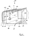
- the second embodiment of the concept of the awning construction according to the invention assumes that its rod parts G form a preassembled structural unit BE with the tent sheets Z ( Fig. 10 ) and at least one pressure body 105 that can be filled with a fluid is integrated into this structural unit BE.
- the pressure element 105 is arranged below or within the tent sheets Z, so that the latter in the manner of a cover layer corresponds to the top of the structural unit BE in the starting position shown Fig. 10 form.
- the pressure body 105 is arranged outside the tent webs Z cooperating with the linkage G in such a way that the pressure body 105 to be connected to the linkage G then forms the outer layer of the structural unit BE at least in regions. This embodiment is not shown.
- the concept of the structural unit BE with the pressure body 105 which can be filled with a fluid, is based on the fact that with comparatively simple means for awnings 100 of the type shown, an erection or dismantling aid is achieved.
- the technical implementation is not limited to a single fluid as filler material, since it is conceivable that the preferably single-layer pressure body 105 can also be designed as a double-walled hose or cushion element, so that this cushion element can be filled with either liquid or air.
- the preferred embodiment of the system provides that the pressure body 105 is comparatively simple to integrate into the structural unit BE and is transportable in this inserted airbag 106 is formed.
- This pressure body 105 which is inflatable to the airbag 106, can be moved from a folded transport position (similar Fig. 10 ) are inflated to the erection and dismantling aid in such a way that an auxiliary element in the manner of an "airbag system" can be used for the construction of the awning 100 and additional safety measures are unnecessary for the user.
- a filling opening 107 which can be connected to a pump system (not shown) is provided on the airbag 106, so that a corresponding filling volume which raises the airbag 106 can be introduced in an arrow direction AA.
- the structural unit BE is then lifted overall, the parts in the form of the vertical struts 108, 109 and respective horizontal rods 110, 111, 112, 113 being evident in a broken line representation ( Fig. 10 ) - Shift position of use largely automatically.
- This stroke movement is shown in principle by an arrow HA. It goes without saying that during this lifting process HA the tent sheet Z is also moved and this then the (in Fig. 11 apparent) takes top position.
- the airbag 106 located as an erection aid in the set-up awning 100 can be opened in its at least one opening area 114 (dash-dot line, Fig. 11 ) are opened and the entire airbag 106 remains in the awning 100 like an inner wall (illustration: inner wall with intersecting wavy lines, Fig. 11 ).
- the airbag 106 is already in its initial position ( Fig. 10 ) can be connected to the linkage G. It is also provided that the airbag 106 opened in the extended inflation position is only then connected to the inner linkage G, in particular in the area of the rod parts 111 to 113, in such a way that a complete “double-layered” roof skin for the awning 100 is reached.
- the above-described set-up system with the structural unit BE is designed in such a way that it can be handled as an autonomous unit with the inner linkage G and the airbag 106 provided on the inner wall thereof and can be moved into the area of the camping vehicle 102.
- the immediate usable space of the camping vehicle 102 is then expanded by the awning 100 in a design known per se.
- the concept of the inflatable airbag 106 also provides that after assembly of the system, the airbag 106 on the inside can be permanently fixed to the frame G and / or the tent sheet Z by means of detachable connecting means 115. It is also conceivable that the airbag 106 - after fulfilling its auxiliary function - is removed from the system as a whole.
- the airbag 106 in turn can be in the area of its Walls can be composed of several wall parts, which can also be double-layered or coated. It is also provided that, when the airbag 106 is inflated, at least one partial area forming the base wall part can be removable. For the process of dismantling the awning, this is to be connected again to the remaining wall parts of the airbag 106 in such a way that the closed "fillingbag" structure is reached and inflatable.
- Fig. 11 is the structural unit BE - in contrast to the boom construction G according to Fig. 10 - Provided with a support beam 116 and a cantilever arm 117 boom G.
- a special guide movement according to arrow FE is achieved in the area of the linkage G and the cantilever arm 117 is thus shifted into its final position.
- a recess 118 which receives the cantilever arm 117, so that an unimpeded up and down movement is possible.
- tent sheet Z forming the roof of the awning 100 is now placed over these two parts of the structural unit BE, which tent sheet Z can consist of side and / or ceiling walls 103, 104 and corresponding window parts, door sections, bottom wall parts (not shown) are also conceivable .
- the airbag 106 provided as a pressure body is inflated and the entire prehistoric system is thus moved into the standing position.
- the awning 100 can now be moved towards the camping vehicle 102, and here the connection known per se takes place via piping profiles or zippers (at 115).
- the connection known per se takes place via piping profiles or zippers (at 115).
- the floor mats or tarpaulins usually provided in the awning 100 are brought into the corresponding functional position after the inflation process become.
- Corresponding additional partial areas can be provided in the bottom area of the airbag 106, which are unfolded during the inflation process and, as a tarpaulin or cover parts, improve the visual impression of the interior of the awning 100.
- the known additional parts in the form of hooks or nails can be fixed on the floor side to fix the tent sheets Z.
- the inner tent produced in this way provides an efficient seal against the ingress of water or air.
- a felt layer or the like which absorbs water in particular, can be introduced, so that the cooling of the awning 100 is possible with little effort by appropriate evaporation cooling.
- the layer of felt or the like which absorbs water can also be provided as a fixed layer on the airbag 106 and / or the tent sheets Z.
- the double-walled design of the awning 100 according to the invention also has an effect on a possible heating period, since the heat dissipation is reduced to an optimally low value by the double-walled structure of the cover.
- the system of the airbag 106 forming the inner wall can be used in hot summer periods to close the airbag 106 and to fill it with fresh air so that there is an effective air exchange and the interior of the awning 100 is optimally cooled. Warm air can also be blown into the space so that the interior does not cool down in colder seasons.
- the awning-airbag system 100 can be retrofitted to all commercially available awnings, since the airbag 106 can also be inserted into the interior of known awnings and inflated in this position. After that, it can be used at least as a disassembly aid with little effort. In the event that the rod parts of other types of awnings are suitable for the system according to the invention, the assembly aid can also be used here.
- the double-layer design of the awning 100 with the airbag 106 forming the inner wall also enables the use of "silent ventilation", since a ventilation fan operated, for example, with solar power can be directed into the space between the inner wall and the upper tent sheet Z. In this way, damage caused by mold or the like and the consequences of water are reliably avoided even when the user is absent. The condensation water that arises in the area of the awning 100 is drained off with little effort by the “silent ventilation”.
- These attachment structures 120 are formed from respective fabric panels, so that in the interior of the awning 100, additional storage compartments, carrying hooks, cupboard troughs or the like.
- Usage contours 121 can also be “automatically” set up.
- additional compartment walls are integrated in the airbag 106, so that Corresponding partitioned areas are defined in the erected construction (not shown).
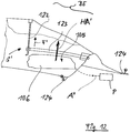
- Fig. 12 the awning-airbag system is shown in the area of a rod G ', which is formed from a vertical guide rod 122 and a substantially horizontal tension rod 123 (similar Fig. 11 ).
- the essentially one-piece tent sheet Z which can be fixed on the bottom by holding parts 124, is also raised here (arrow H ') when a filling process is initiated (arrow A "), so that the tensioning rod 123 is simultaneously displaced into its upper position of use (arrow F ').
Landscapes
- Engineering & Computer Science (AREA)
- Architecture (AREA)
- Civil Engineering (AREA)
- Structural Engineering (AREA)
- Physics & Mathematics (AREA)
- Fluid Mechanics (AREA)
- Tents Or Canopies (AREA)
Description
- Die Erfindung betrifft ein Vorzelt für eine Campingunterkunft in Form eines Campinganhängers, eines Wohnwagens, eines Wohnmobils o. dgl. beim Camping nutzbaren Fahrzeugs gemäß dem Oberbegriff des Anspruchs 1 .
- Die Ausrüstung von Campingunterkünften mit einem zusätzlichen Vorzelt ist seit langem bekannt. Gemäß
DE 83 08 022 wird bereits ein als Baueinheit ausgebildetes Vorzelt vorgeschlagen, das beim Aufstellen mit einem Gerüst verbunden wird. Dabei sind die Teile des Gerüstes an einem Seitenrandbereich der Campingunterkunft abzustützen, so dass mit lediglich zusätzlichen vertikalen Stützen ein dachartiger Überbau mit zumindest oberseitigen Zeltbahnen gebildet wird. Die Handhabung der Einzelteile erfordert entsprechenden Sachverstand beim Nutzer der Baueinheit. - Bei einer Konstruktion gemäß
DE 35 32 025 A1 ist ein Vorzelt vorgesehen, bei dem ein Gerüst aus jeweiligen Profilleisten zu einem aus waagerechten und senkrechten Teilbereichen zusammengesetzten System aufgebaut werden kann. In die Freiräume dieses Gerüstes im Bereich zwischen den jeweiligen Profilschienen sind dann spezielle Luftkammerelemente einzusetzen, so dass ein weitgehend geschlossener Innenraum gebildet werden kann. Diese Luftkammerelemente sind zusätzlich an Kederleisten des Wohnwagens zu fixieren, so dass eine Verbindung des Bausatzes mit der Campingunterkunft gebildet wird. Die einstückigen Luftkammerelemente sind dabei als Einzelteile zum Aufstellort zu transportieren, so dass ein vergleichsweise hoher Transportaufwand bei gleichzeitigem hohem Raumbedarf entsteht. Die Fixierung der Einzelelemente des Gerüstes und das Anbringen der Luftkammerelemente sind aufwändig. - Bei einem Vorzelt für speziell für Camping ausgerüstete Fahrzeuge, insbesondere Wohnwagen oder Wohnmobile, gemäß
DE 10 2011 111 730 A1 ist eine in üblicher Ausführung an der Fahrzeugwand festlegbare Konstruktion vorgesehen, die zwischen den wandseitigen bzw. deckenseitigen Zeltbahnen eine luftdurchlässige Zone bildet. Dabei ist ein luftdurchlässiges Zusatzteil beim Aufstellen des Gerüstes in den Zwischenraum einzubringen. Bei dieser Konstruktion ist in üblicher Ausführung zuerst das Gestänge aus jeweiligen Strebenteilen zu errichten, und danach kann die zumindest bereichsweise doppellagige Zeltbahn-Konstruktion mit den Abstützelementen verbunden werden. Bei diesem Ablauf ist eine aufwändige Bauanleitung zu befolgen, so dass von ungeübten Nutzern eine langzeitige Montage bzw. Demontage zu bewältigen ist. - Bekannt sind auch andere Arten von Campingunterkünften, bei denen jeweilige ein Vorzelt bildende Zusatzbaugruppen bereits in das Campingfahrzeug integriert sind. Dabei wird durch entsprechende Aufklappbewegungen im Bereich des Fahrzeugs ein zusätzlicher Nutzraum gebildet (
US 4,113,301 ;US 5,080,426 ;US 5,419,607 ). Bei einer weiteren Ausführung von Campingunterkünften mit Überdachungen sind jeweilige aufblasbare Systeme am Fahrzeug vorgesehen. Diese Fahrzeuge bilden dann ein als Campingfahrzeug nutzbares integriertes System (US 4,093,302 ;US 4,296,960 ;US 5,692,795 ;US 201010230999 A1 - Ebenfalls bekannt sind variable Ausführungen von Zeltkonstruktionen für insbesondere kommerzielle Zwecke, bei denen ein Aufblasvorgang zur Schaffung eines Nutzraumes vorgesehen ist In
WO 03/006765 A1 - Bei einfacheren Zelt-Systemen werden jeweils aufblasbare Schläuche genutzt (
US 5,987,822 ;US 6,263,617 B1 ;US 6,810,896 B2 ;DE 92 01 195 U1 ;FR 2 845 412 DE 76 02 841 U1 ), so dass unterschiedliche transportable Zeltkonstruktionen als autarke Einheit nutzbar sind. Diese sind jedoch nicht als Vorzelt mit einer Campingunterkunft verbindbar. Ebenfalls bekannt sind modulare Zeltsysteme, bei denen Luftkammern die Funktion eines Zeltgestänges ersetzen (DE 203 05 372 U1 ;DE 201 14 974 U1 ;GB 2 378 925 B DE 90 01 184 U1 ist ein Mehrzweckzelt bekannt, dessen Innenboden als aufblasbarer Bodenabstandshalter ausgebildet ist. - Gemäß
WO 2010/001259 A2 ist ein Campingfahrzeug mit einer aufblasbaren Zeltkonstruktion bekannt, wobei in einem transportablen Anhänger ein Basiszelt mit einer als Vorzeit vorgesehenen Baugruppe ein komplex nutzbares System bilden. Damit ist eine kompakte Einheit geschaffen, die ausgehend vom Basisbehälter des Anhängefahrzeugs als komplettes Campingsystem ausgefaltet und am Ende einer Nutzphase durch einen Absaugvorgang wieder in die Transportstellung gebracht werden kann. Damit wird eine für den Nutzer einen hohen Bedienkomfort aufweisende Campingunterkunft bereitgestellt. - Es ist bekannt, Zelte mittels aufblasbarer rohrförmiger Körper mit Campingfahrzeugen abdichtend zu verbinden (
EP 1 243 723 A1 ). - Die Erfindung befasst sich mit dem Problem, ein Vorzelt für einen Wohnwagen o. dgl. Campingunterkunft so zu gestalten, dass dieses Vorzelt als eine autarke Einheit nutzbar ist, dabei gemeinsam mit innen liegenden Gestängeteilen einfacher aufstellbar sowie demontierbar ist und damit ein verbesserter Bedienkomfort für den Nutzer erreicht wird.
- Die Erfindung löst diese Aufgabe mit einem Vorzelt mit den Merkmalen des Anspruchs 1. Hinsichtlich weiterer Ausgestaltungen der Erfindung wird auf die Ansprüche 2 bis 42 verwiesen.
- Die in unterschiedlichen Ausführungen bekannten Vorzelte für Wohnwagen, Wohnmobile o. dgl. Campingunterkünfte weisen in Gebrauchsstellung jeweilige Decken- und Wandteile bildende Zeltbahnen auf, die von einem das System spannenden Gestänge untergriffen sind. Ein wesentliches Problem bei der Nutzung derartiger Vorzelte ist der bei bekannten Konstruktionen aufwändige Verfahrensablauf beim Aufbau dieser Vorzelte.
- Das erfindungsgemäße Konzept geht in grundlegender erster Ausführung davon aus, dass das Vorzelt aus einer zumindest im Bereich jeweiliger flächiger Seiten-, Dachsowie Bodenwandteile verschließbaren Hüllkonstruktion gebildet ist, so dass diese Hüllkonstruktion in einem zumindest bereichsweise luftdicht geschlossenen Zustand aufgeblasen werden kann. Bei Fortsetzung des "automatischen" Montagevorgangs ist die sich aufrichtende Hüllkonstruktion einfacher zugänglich, und mit geringem Aufwand können Teile des Gestänges in die aussteifende Gebrauchslage gebracht werden.
- Für eine autarke Handhabung der Vorzelt-Baueinheit ist vorgesehen, dass die Hüllkonstruktion im Bereich zumindest einer ihrer flächigen Seitenwandteile mit einer an einer Stützwand o. dgl. Gegenglied der Campingunterkunft anlegbaren Verbindungseinheit versehen wird. Diese Verbindungseinheit ist so ausgelegt, dass die im Wesentlichen geschlossene Hüllkonstruktion bereits in einem zumindest teilweise aufgeblasenen Zustand bis in den Nahbereich der Campingunterkunft verlagert werden kann und hier im Bereich der Verbindungseinheit jeweilige Gegenglieder - beispielsweise an der Außenwand der Campingunterkunft - zur "Andockung" des Vorzeltes bzw. der Hüllkonstruktion genutzt werden.
- Dabei wird die Verbindungseinheit im Bereich einer als die Stützwand vorgesehenen Außenwand der Campingunterkunft festgelegt, wobei hier eine an sich bekannte Keder-Baugruppe genutzt wird. Dabei ist die Verbindungseinheit insgesamt als ein in variabler Breite bereitstellbarer Zeltbahnstreifen ausgebildet, so dass entsprechend der jeweiligen stirnseitigen Kontur an der Hüllkonstruktion eine optimale Verbindung mit dem jeweiligen Gegenglied im Bereich der Campingunterkunft herstellbar ist.
- Die Einbindung des die Verbindungseinheit bildenden Zeltbahnstreifens ist dabei so konzipiert, dass der Zeltbahnstreifen einerseits mit einem ersten Formkeder o. dgl. lösbaren Gegenhalter an der Campingunterkunft gehalten ist und andererseits die lösbare Verbindung des Zeltbahnstreifens zum Wandteil des Vorzeltes hin mittels eines zweiten Formkeders, eines Reiß- und/oder Klettverschlusses hergestellt wird. Es versteht sich, dass in die zumindest bereichsweise aufgeblasene Hüllkonstruktion bzw. an zumindest einer Außenseite dieser Hüllkonstruktion jeweilige Teile des Gestänges einfacher anzubringen sind und bei Fortsetzung des Aufblasvorgangs eine vollständige Aufrichtung des Stangen-Hüllen-Systems erreichbar ist.
- In zweckmäßiger Ausführung sieht das Vorzelt-Konzept vor, dass die Hüllkonstruktion mit den Gestängeteilen als eine weitgehend vormontierte Einheit bereitgelegt wird und mit dem als Hilfsverfahren vorgesehenen Aufblasvorgang im Bereich der Hüllkonstruktion das Füllvolumen bzw. der Innendruck so weit ansteigen, dass auch die Gestängeteile in einer optimalen Aufrichtbewegung geführt sind. Dieser Vorgang kann weitgehend automatisch so lange fortgesetzt werden, bis die gesamte Hüllen-Gestänge-Einheit im aufgeblasenen Zustand erfassbar ist und autark bewegt werden kann. Damit wird deutlich, dass das Vorzelt als eine aufgeblasene Hüllkonstruktion neben der Campingunterkunft freistehend handhabbar ist. Vorteilhaft sieht die technische Umsetzung vor, dass die Einzelkomponenten in Form der Zeltbahnen und jeweiliger Leichtmetall-Gestängeteile ein für die Handhabung geeignetes Gewicht aufweisen.
- In unterschiedlichen Ausführungen dieses Vorzeltes ist denkbar, dass die mit zumindest Teilstreben des Gestänges ausgesteifte Hüllkonstruktion eine freistehende Baueinheit bildet und diese ggf. auch ohne das "nebengeordnete" Campingfahrzeug in einer vorgesehenen Gebrauchsstellung als "Einzelzelt" verbleiben kann. Dies ist insbesondere dann von Interesse, wenn das Wohnmobil, der Campinganhänger o. dgl. Fahrzeug unabhängig von der autark aufgestellten Vorzelt-Baueinheit für eine andere Benutzung vorgesehen ist. In diesem Falle können dann jeweilige zwischen Wohnmobil und Vorzelt befindliche Verbindungsteile gelöst und das Fahrzeug bewegt werden. Es versteht sich, dass das Fahrzeug nach Rückkehr an den Aufstellort dann wieder mit dem Vorzelt verbunden werden kann.
- Ausgehend von einer Optimierung des Pressluft-Aufstellvorgangs sieht das Konzept des Vorzeltes vor, dass dessen Hüllkonstruktion in geschlossenem Zustand auch teilweise aufgeblasen werden kann. Danach können zumindest jeweilige Teilstreben des Gestänges in diese Hüllkonstruktion so eingebracht werden, dass nachfolgende Aufstellbewegungen und Ausrichtungen des Vorzeltes einfacher möglich sind. Dabei kann das Gestänge auch von jeweiligen in die Wandteile bzw. die Zeltbahnen integrierten Aussteifungselementen gebildet sein, die durch den Aufblasvorgang bereits in die vorgesehene Stellung gelangen bzw. durch einfache Handbewegungen optimal ausgerichtet werden können. Die Aussteifungselemente können dabei im Bereich jeweiliger Gelenke o. dgl. Verbinder so gegenseitig abgestützt sein, dass in diesen Bereichen zumindest phasenweise beim Aufblasen eine gesteuerte Mitbewegung erfolgt und damit die vorgesehene Gebrauchslage weitgehend ohne zusätzliche Handgriffe erreicht wird.
- In zweckmäßiger Ausführung des aus mehreren Zeltbahnen bestehenden Vorzeltes bzw. der Hüllkonstruktion ist vorgesehen, dass das zugeordnete Gestänge mit jeweiligen über eine Öffnung in die aufgeblasene Hüllkonstruktion einführbaren Stangenteilen versehen ist. Diese können mittels jeweiliger Schlaufen, Klettverschlüsse o. dgl. Verbinder an der Hüllkonstruktion platziert und in einer endgültigen Einbaulage fixiert werden.
- Es versteht sich, dass im Bereich zwischen Gegenglied(ern) und der zumindest einen Verbindungseinheit vorzugsweise eine jeweils fluiddichte Verbindung herstellbar ist, so dass auch - bei Anwendung lösbarer Verbindungsglieder - ein ungewollter Eintritt von Niederschlagswasser in den Nutzraum-Bereich unterhalb der Verbindungseinheit vermieden wird.
- Mit diesem als Verbindungseinheit vorgesehenen Zeltbahnstreifen wird - in der montierten Gebrauchsstellung des Systems - zwischen Vorzelt und Campingunterkunft ein zusätzlicher Nutzraum definiert, der dabei zumindest oberseitig durch den Zeltbahnstreifen abgedeckt ist. Der Zeltbahnstreifen kann dabei so dimensioniert werden, dass eine den Nutzraum zwischen Vorzelt und Campingunterkunft vollständig überdeckende Schließkontur definiert ist. Ebenso ist denkbar, dass die bahnförmige Verbindungseinheit bis hin zum Bodenwandteil des Vorzeltes verläuft und hier eine geschlossene Verbindung hergestellt wird. Damit wird ein bis zum Boden hin geschlossener Zwischenraum zwischen dem Vorzeit und der Campingunterkunft erreicht.
- Der einen zusätzlichen Nutzraum definierende Zeltbahnstreifen kann für eine effektive Nutzung des oberseitig abgedeckten Zwischenraums auch eine Ausbildung mit Lüftungsöffnungen aufweisen, so dass im Bereich dieser Abdeckung des Zwischenraums eine optimale Belüftung möglich ist und die Ableitung von Wasserdampf geregelt werden kann.
- Bei dem Konzept der aufblasbaren Hüllkonstruktion sind unterschiedliche Varianten zum Aufbau des erhöhten Innendrucks in die Hüllkonstruktion denkbar. Vorteilhaft ist dabei die Hüllkonstruktion im Bereich des zur Campingunterkunft gerichteten Seitenwandteils mit einer Gebläseöffnung versehen, so dass vorzugsweise ein im Bereich der Campingunterkunft vorgesehenes Gebläse mit Elektroantrieb nutzbar ist. Dieses Gebläse kann dann beispielsweise im Bereich der Verbindungseinheit mittels eines Luftleitschlauches o. dgl. Verbinder überbrücken, so dass die Lufteinbringung an weitgehend beliebigen Positionen der Hüllkonstruktion möglich ist. Ebenso ist denkbar, dass im Bereich der Gebläseöffnung ein autarkes Gebläse angesetzt wird, das beispielsweise unabhängig vom Wohnmobil bzw. der Campingunterkunft an ein externes Stromnetz angeschlossen werden kann.
- Die Konstruktion des aufblasbaren Vorzeltes - als einen zusätzlichen Nutzraum bildendes Campingelement - kann an unterschiedliche Ausführungen von Gestängen angepasst werden. In einer einfachen Ausführung ist denkbar, dass die Hüllkonstruktion im Bereich eines schwenkbar an der Campingunterkunft gehaltenen Schwenkgerüstes verlagerbar ist, so dass während oder nach dem Abschwenken aus einer Verwahrstellung der im Bereich der Hüllkonstruktion vorgesehene Aufblasvorgang einleitbar ist. Dabei sind nur wenige zusätzliche Handbewegungen notwendig, um das Vorzelt dann in der vorgesehenen Gebrauchslage zu fixieren.
- Eine weitere Ausführung der erfindungsgemäßen Vorzelt-Konstruktion sieht vor, dass die Hüllkonstruktion im Bereich eines Wohnmobils, in dessen Dachbaugruppe integriert ist. Hier nimmt die Hüllkonstruktion eine Transportstellung ein, aus der heraus die Hüllkonstruktion beim Einsatz einer an das System anschließbaren Aufblasvorrichtung verlagert werden kann. Dieser Aufblasvorgang kann dabei vorteilhaft unmittelbar aus dem Innenraum des Wohnmobils erfolgen, so dass durch den sich im Dachbereich aufbauenden erhöhten Luftdruck die Hüllkonstruktion in einer bevorzugten Hub- und Ausfahrrichtung verschwenkt wird. Dabei wird im Zusammenwirken mit zumindest einem Gestängeteil die vorgesehene Einbauposition neben dem Wohnmobil weitgehend "automatisch" erreicht.
- Es versteht sich, dass die Hüllkonstruktion gemeinsam mit einem oder mehreren Teilen des Gestänges bewegt werden kann und dabei durch den Aufblasvorgang diese Baueinheit in einer neben dem Wohnmobil befindlichen Lage positioniert wird. Durch wenige zusätzliche Handgriffe kann dann die endgültige Benutzungslage des Vorzeltes hergestellt werden.
- Eine weitere Ausführung des erfindungsgemäßen Vorzeltes sieht vor, dass die Gestängeteile mit den Zeltbahnen eine vormontierbare Baueinheit bilden, die in üblicher Vorgehensweise am Aufstellort auslegbar ist. In diese erweiterte Baueinheit ist nunmehr ein zumindest bereichsweise mit einem Fluid füllbarer Druckkörper als zusätzliches Bauteil integriert. Dieses Druckkörper-Bauteil wirkt mit den Gestängeteilen und der zumindest einen Zeltbahn als eine einfach handhabbare Funktionseinheit zusammen. Dabei wird der neuartige Druckkörper als eine Aufricht- oder Demontagehilfe eingesetzt.
- Der mit einem Fluid füllbare Druckkörper kann dabei in unterschiedlichen räumlichen Gestaltungsformen so ausgebildet sein, dass der am Einsatzort mit dem Fluid zu füllende Druckkörper wahlweise auch innerhalb oder außerhalb der Zeltbahnen mit der Baueinheit zusammenwirken kann. In jedem Fall wird erreicht, dass in einer entsprechenden Füllphase des Druckkörpers eine synchrone Mitbewegung von Zeltbahnen und Gestängeteilen realisierbar ist und damit ein "automatischer" Aufrichtvorgang abläuft, dessen Vorteile insbesondere für ältere Nutzer offensichtlich sind.
- Das Konzept des Druckkörpers kann insbesondere so ausgeführt werden, dass dieser in Form eines einlagigen oder zumindest bereichsweise doppelwandigen Schlauch- oder Kissenelementes ausgeführt wird. Damit ist die Möglichkeit eröffnet, den Druckkörper wahlweise mit Flüssigkeit und/oder Luft zu füllen und so die beabsichtigte Aufricht bzw. Demontagehilfe zu realisieren. Diese Wirkkombination unterscheidet sich wesentlich von den bekannten "Füll-Schläuchen", die an Stelle der stabilen Zeltstangen mit einer Dachhaut verbunden sind.
- In zweckmäßiger Ausführung ist vorgesehen, dass der Druckkörper als ein vergleichsweise einfach aufgebauter und mit geringem Aufwand in die Baueinheit aus Gestängeteilen und Zeltbahnen einlegbarer Luftsack ausgebildet wird. Dieser als Luftsack ausgebildete Druckkörper kann dabei seinerseits aus bahnförmigen Einzelteilen bestehen, die in flächiger Auslegung raumsparend transportabel sind und am Einsatzort in einen Öffnungs- bzw. Schließbereich zu dem geschlossenen Luftsack verbunden werden. Für die vorbeschriebene Nutzung des geschlossenen Luftsackes ist an diesem insbesondere eine an ein Pumpsystem anschließbare Füllöffnung vorgesehen. Diese Füllöffnung kann dabei als fest installierter Anschlussstutzen ausgeführt sein.
- Im Bereich jeweiliger durch Druckverschlüsse, einen Reißverschluss o. dgl. Verbinder definierter Öffnungs- bzw. Schließbereiche kann eine Anschlusszone vorgesehen sein, so dass in deren Bereich ein Füllschlauch o. dgl. Verbindungselement in den Luftsack einführbar bzw. an diesen anschließbar ist, derart, dass im Innenraum des Luftsackes ein dessen Volumen vergrößernder Überdruck aufgebaut werden kann. Denkbar ist auch, eine im Luftsack befindliche Pumpe vorzusehen, so dass unmittelbar im Innenraum des Luftsackes der Füllvorgang erfolgt.
- Eine weitere Ausführung sieht vor, dass das System unabhängig von einer separaten Pumpe auch mit einem Druckgas aus einer Druckflasche, Kartusche o. dgl. gefüllt werden kann. Dabei ist die Anwendung von industriellen Gasen, CO2, Helium o. dgl. nicht brennbaren Füllgasen denkbar.
- Während dem Einsatz des sich füllenden Luftsackes als Montagehilfe - wobei mittels des sich aufrichtenden Luftsackes die Gestängeteile bis in die Nähe ihrer Gebrauchslage angehoben und dabei gleichzeitig das über den Gestängeteilen befindliche System der Zeltbahnen mit angehoben wird - kann der in seiner Grundstruktur ebenfalls "bahnförmige" Luftsack als eine zusätzliche Innenwand im Innenraum des Vorzeltes verbleiben. Dabei ist denkbar, nach dem Aufblasen zumindest einen der die bahnförmigen Einzelteile des Luftsackes verbindenden Öffnungsbereiche zu betätigen. Danach kann der Luftsack als eine Innenwand - nach Art einer Auskleidung - mit den aufgestellten und versteiften Gestängeteilen verbunden werden.
- Damit wird erreicht, dass zwischen der außen liegenden Zeltbahn und der vom Luftsack an der Innenseite des Gestänges gebildeten Innenwand eine zusätzliche Luftschicht gebildet wird und diese nach Art einer Klimazone eine zusätzliche Komfortverbesserung am Vorzelt ermöglicht.
- Das gesamte Aufbau-System dieses mehrlagigen Vorzeltes sieht vor, dass der in Form des Luftsackes ausgebildete Druckkörper bereits in ungefülltem Zustand mit den vormontierten Gestängeteilen bereichsweise bedeckt werden kann, über diesen Gestängeteilen die zumindest teilweise entfalteten Zeltbahnen positioniert werden und danach das Füllen des Luftsackes mittels einer insbesondere motorisch betätigten Luftpumpe erfolgt. Nach diesem Füllvorgang ist ein Vorzelt aufgebaut, das mit den innen liegenden Gestängeteilen und an diesen als Innenwand vorgesehenen Luftsack als eine autarke Einheit "freistehend" handhabbar ist. In üblicher Einbaulage wird nunmehr diese vollständig oder teilweise aufgerichtete autarke Einheit in den Bereich nahe des Campingfahrzeugs verlagert und hier über eine an sich bekannte randseitige Verbindung die vorgesehene Einbaulage des Vorzeltes endgültig hergestellt.
- Nach dem vollständigen Ausrichten des Vorzeltes kann der innen liegende Luftsack über lösbare Verbindungsmittel am Gestänge und/oder an der Zeltbahn fixiert werden. Denkbar ist dabei, dass das Vorzelt als eine mehrlagige Zeltbahn ausgebildet ist und diese mit dem die Innenwand bildenden Luftsack zusammenwirkt. Dieser kann seinerseits im Bereich seiner Wandungen aus mehreren Wandteilen zusammengesetzt sein, so dass für unterschiedliche Zelttypen entsprechend anpassbare Größen von Luftsäcken bereitgestellt werden und diese dann jeweils optimal als Innenwand umrüstbar sind.
- Das wandseitig geschlossene System des aufblasbaren Luftsackes sieht vor, dass von diesem in aufgeblasenem Zustand zumindest ein Bodenwandteil abnehmbar sein kann, so dass die ursprüngliche Struktur des Luftsackes nur noch als Teilbereich der Innenwandung verbleibt.
- In einer Phase der Demontage des Systems ist vorgesehen, dass der Luftsack wieder komplett aus sämtlichen Wandteilen im Bereich seiner Verbindungsbereiche zusammengesetzt wird, der Luftsack weitgehend geschlossen wird und danach - durch einen entsprechenden Pumpvorgang - im Innenraum ein geringer Überdruck erzeugt wird. In dieser Phase können dann die Gestängeteile aus ihrer aussteifenden Lage gelöst werden, so dass diese Teile "lose" auf dem Luftsack aufliegen. Nachfolgend kann die Luft des Luftsackes abgelassen werden. Denkbar ist auch, diesen weitgehend automatischen Zusammenfaltvorgang durch eine zusätzliche Luftabsaugung zu unterstützen.
- Da das System dann vergleichsweise langsam zusammengefaltet wird, können die Nutzer durch entsprechende Hilfsbewegungen die exakte Lage der Gestängeteile und der äußeren Zeltbahn beeinflussen, so dass nach vollständiger Entleerung des Luftsackes ein weitgehend kompaktes System für den Abtransport bereitsteht.
- Weitere Einzelheiten und vorteilhafte Ausgestaltungen des erfindungsgemäßen Vorzeltes ergeben sich aus der nachfolgenden Beschreibung und der Zeichnung, in der mehrere Ausführungsbeispiele der Vorrichtung mit unterschiedlichen Hüllkonstruktionen näher beschrieben sind. In der Zeichnung zeigen:
- Fig. 1
- eine Perspektivdarstellung eines Vorzeltes im Bereich eines Wohnanhängers gemäß dem Stand der Technik,
- Fig. 2
- eine Prinzipdarstellung ähnlich
Fig. 1 mit einer ersten Ausführung des erfindungsgemäßen Vorzeltes als autarke Einheit neben dem Campinganhänger, - Fig. 3
- eine Prinzipdarstellung des Vorzeltes gemäß
Fig. 2 in einer Phase beim Aufblasen der Hüllkonstruktion, - Fig. 4
- eine Prinzipdarstellung ähnlich
Fig. 2 mit dem Vorzelt und dessen Montage am Campinganhänger, - Fig. 5
- eine vergrößerte Ausschnittsdarstellung einer zur Montage der Baueinheiten vorgesehenen Verbindungseinheit,
- Fig. 6
- eine Prinzipdarstellung der Hüllkonstruktion mit einer veränderten Ausführung im Bereich des Gestänges,
- Fig. 7
- eine Prinzipdarstellung der auf einem Campingfahrzeug, einem Wohnmobil o. dgl. Einrichtung transportablen Hüllkonstruktion in Transportstellung,
- Fig. 8
- eine Perspektivdarstellung der Hüllkonstruktion in verlagerter Gebrauchsstellung,
- Fig. 9
- eine Prinzipdarstellung der Rückverlagerung der Hüllkonstruktion auf das Dach des Wohnmobils,
- Fig. 10
- eine schematische Perspektivdarstellung einer zweiten Ausführung des erfindungsgemäßen Vorzeltes in einer ersten Montagephase mit leerem Druckkörper im Bereich eines Campingfahrzeuges,
- Fig. 11
- eine schematische Darstellung ähnlich
Fig. 10 mit einem aufgeblasenen Luftsack im Bereich eines eine geänderte Gestängekonstruktion aufweisenden Vorzeltes, und - Fig. 12
- eine schematische Darstellung eines Luftsackes im Bereich einer geänderten Gestängekonstruktion.
- In
Fig. 1 ist ein insgesamt mit 1 bezeichnetes Vorzelt im Bereich einer Campingunterkunft 2 dargestellt, wobei diese in Form eines Campinganhängers, eines Wohnmobils, eines Faltcaravans o. dgl. Einrichtung ausgebildet sein kann. Dabei ist das mit dieser Einrichtung 2 verbundene Vorzelt 1 mit jeweiligen aus Zeltbahnen Z gebildeten Wandteilen 3, 4, 5, 6, 7 versehen, und diese werden in Gebrauchsstellung zumindest bereichsweise durch ein Gestänge G ausgesteift. - Das erfindungsgemäße Konzept sieht vor, dass das Vorzelt 1 aus einer zumindest im Bereich der jeweiligen Seiten-, Dach- sowie Bodenwandteile 3, 4, 5, 6, 7 verschließbaren und damit in einem zumindest bereichsweise fluiddichten Zustand aufblasbaren Hüllkonstruktion H (
Fig. 3 ) gebildet ist. Diese Hüllkonstruktion H ist dabei so ausgeführt, dass in dem zumindest bereichsweise aufgeblasenen Zustand eine autarke Bewegung des Systems (Pfeil B,Fig. 2 ) möglich ist. Damit ist das bisher auf Campingplätzen übliche System einer "Zwangsverbindung" von Vorzelt 1 und zugehöriger Einrichtung 2 erfindungsgemäß nicht mehr vorgesehen. Vielmehr kann die aufgeblasene Hüllkonstruktion H auch neben der Campingunterkunft 2 freistehend als Nutzraum aufgestellt werden. - In zweckmäßiger Ausführung ist dabei eine freistehende Baueinheit dadurch gebildet, dass die mit zumindest Teilstreben 8, 9 (
Fig. 4 ) des Gestänges G ausgesteifte Hüllkonstruktion H hinreichend stabil fixiert wird. - In der Montagephase ist vorgesehen, dass die Hüllkonstruktion H in ihrem geschlossenen Zustand zumindest teilweise aufgeblasen (
Fig. 3 ) und mit den Teilstreben 8, 9 des Gestänges G zumindest bereichsweise ausgesteift wird. Dabei ist denkbar, dass das Gestänge G von jeweiligen in die Wandteile bzw. die Zeltbahnen Z integrierten Aussteifungselementen (nicht dargestellt) gebildet ist. Die Konstruktion derartiger Aussteifungselemente sieht dabei vor, dass diese zumindest phasenweise beim Aufblasen mitbewegt werden, dabei automatisch eine Fixierposition einnehmen und damit ein ungewolltes Zusammenfallen des Systems (z. B. beim Austreten der Druckluft aus dem Innenraum) vermieden ist. - Die optimale Gestaltung des Gestänges G sieht vor, dass dieses mit jeweiligen über eine Öffnung 10 in die bereits teilweise aufgeblasene Hüllkonstruktion H einführbaren Stangenteilen 11, 12 (
Fig. 3 ) versehen ist (ähnlich: Teilstreben 6, 7;Fig. 4 ). Diese können beim Aufblasvorgang (Pfeil E) mitbewegt werden (Pfeil F;Fig. 3 ). - Aus einer Zusammenschau von
Fig. 2 undFig. 4 wird deutlich, dass die Hüllkonstruktion H im Bereich zumindest einer ihrer flächigen Seitenwandteile 6 mit einer an einer Stützwand 13 o. dgl. Gegenglied der Campingunterkunft 2 anlegbaren Verbindungseinheit E, E' versehen ist. Mit dieser zumindest einen Verbindungseinheit E wird erreicht, dass die im Wesentlichen geschlossene Hüllkonstruktion H in einem zumindest teilweise aufgeblasenen Zustand im Bereich der Campingunterkunft 2 in einer Verbindungsposition festlegbar ist. - Aus der Darstellung gemäß
Fig. 2 wird deutlich, dass der autarke Aufblasvorgang der Hüllkonstruktion H mittels einer an ein Gebläse 14 angeschlossenen Saug- bzw. Druckleitung 15 dazu genutzt wird, die aufgestellte Vorzelt-Hüllkonstruktion H mit einem Abstand A zum Campingfahrzeug 2 aufzustellen. In dieser Phase können die Bauteile entsprechend ihrer optimalen Lage ausgerichtet werden. Danach eröffnet sich die Möglichkeit, das Vorzelt 1 insgesamt zur Einrichtung 2 hin zu bewegen (Pfeil B). Auch durch eine vergleichsweise einfachere Bewegung der Einrichtung 2 kann diese in eine Position so rangiert werden, dass die beiden Teile 1 und 2 nunmehr mit geringem Aufwand verbunden werden können. - Für diesen Verbindungsvorgang wird nunmehr die Verbindungseinheit E bzw. E' genutzt, wobei diese wahlweise bereits an der Einrichtung 2 an einem Gegenglied 16 befestigt sein kann (E';
Fig. 2 ). Alternativ ist vorgesehen, dass die Verbindungseinheit E in einer Vormontagestellung (nicht dargestellt) an der Hüllkonstruktion H festgelegt ist (Fig. 4 ,Fig. 5 ). - Es versteht sich, dass mit der Verbindungseinheit E im Bereich zwischen Gegenglied 16 und Verbindungseinheit E eine fluiddichte Ausführung vorgesehen ist. Dazu sind im Bereich der Hüllkonstruktion H oder im Bereich der an der Campingunterkunft 2 vorgesehenen Gegenglied-Ausführung 16 jeweilige lösbare Verbindungsglieder vorgesehen.
- Die Darstellung gemäß
Fig. 2 verdeutlicht, dass in zumindest teilweise aufgeblasenem Zustand der Hüllkonstruktion H die Verbindungseinheit E mit einer als die Stützwand 13 vorgesehenen Außenwand der Campingunterkunft 2 mittels einer Kederbaugruppe o. dgl. Gegenglied 16 verbindbar ist. - Aus der vergrößerten Ausschnittsdarstellung gemäß
Fig. 5 wird deutlich, dass ein die Verbindungseinheit E bildender Zeltbahnstreifen 17 einerseits mit einem ersten Formkeder K o. dgl. lösbaren Halter 16' an der Campingunterkunft 2 festlegbar ist. Andererseits ist die lösbare Verbindung des Zeltbahnstreifens 17 zu einem Ansatz 6' des Wandteils 6 des Vorzeltes 1 hin mittels eines zweiten Formkeders K', eines Reiß- und/oder Klettverschlusses herstellbar ist. - Die vorzugsweise Ausführung der Verbindungseinheit E in Form des Zeltbahnstreifens 17 ermöglicht eine optimale Verbindung der Bauteile, wobei der Zeltbahnstreifen 17 mit geringem Aufwand an die stirnseitige Kontur im Bereich der Wandung 6 der Hüllkonstruktion H anpassbar ist. Ausgehend von diesem Konzept des Zeltbahnstreifens 17 ergibt sich mit geringem Aufwand eine "Vorzeiterweiterung", da der Zeltbahnstreifen 17 im Bereich der Verbindungseinheit E in Gebrauchsstellung des Vorzeltes 1 zwischen diesem und der Campingunterkunft 2 einen zumindest oberseitig abgedeckten Nutzraum gemäß Abstandsmaß A' (
Fig. 4 ) definiert. - Das Konzept sieht dabei vor, dass der Zeltbahnstreifen 17 eine den Nutzraum A' zwischen Vorzelt 1 und Campingunterkunft 2 vollständig überdeckende Schließkontur (wie in
Fig. 4 dargestellt) aufweisen kann. Diese bahnförmige Verbindungseinheit E kann dabei so weit geführt werden, dass eine Verbindung auch im Bereich des Bodenwandteils 5 des Vorzeltes 1 erreicht wird. In der Ausführung gemäßFig. 5 ist der Zeltbahnstreifen 17' in einer denkbaren doppellagigen Ausführung verdeutlicht. Dabei sind im Bereich dieses Zeltbahnstreifens 17' jeweilige mit einer Abdeckung 18 versehene Lüftungsöffnungen 19 vorgesehen. - Aus einer Zusammenschau von
Fig. 3 undFig. 4 ergibt sich, dass die Hüllkonstruktion H im Bereich des zur Campingunterkunft 2 gerichteten Seitenwandteils 6 mit einer Gebläseöffnung 15, 15' versehen sein kann. Dabei ist im Bereich der Campingunterkunft 2 das mit der Hüllkonstruktion H verbindbare Gebläse 14 vorgesehen, und dieses weist einen den Bereich der Verbindungseinheit E überbrückenden Luftleitschlauch 15' auf. Im Unterschied zu dieser "integrierten" Variante gemäßFig. 4 zeigt die Darstellung gemäßFig. 3 die Anordnung der Gebläseöffnung 15 im Bereich eines autarken Gebläses 14. - In
Fig. 6 ist eine weitere Ausführungsform der Hüllkonstruktion H dargestellt, wobei diese im Bereich eines schwenkbar an der Campingunterkunft 2 gehaltenen Schwenkgerüstes 20 verlagerbar (Pfeil D) und aufblasbar gehalten ist. Im aufgeblasenen Zustand wird dieses System insbesondere durch jeweilige bodenseitige Verbinder 21 fixiert. - In einer weiteren Ausführung (
Fig. 7 bis Fig. 9 ) ist vorgesehen, dass die vorbeschriebene Hüllkonstruktion H im Bereich eines Wohnmobils, eines Wohnwagens o. dgl. Einrichtung 2 insbesondere in dessen Dachbaugruppe 22 integriert werden kann. Aus einer dabei eingenommenen Transportstellung (Fig. 7 ) kann die Hüllkonstruktion H durch den Einsatz einer an diese Ausgangslage entsprechend angepassten Aufblasvorrichtung 23 verlagert bzw. herausbewegt werden. - Dabei ist vorgesehen, dass die Aufblasvorrichtung 23 unmittelbar in dem Wohnmobil 2 vorgesehen sein kann (
Fig. 7 ). Damit wird die Hüllkonstruktion H - gemeinsam mit einem oder mehreren Teilen des Gestänges G - mittels einer variabel steuerbaren Hub-Schwenk-Verlagerung (Pfeil S, S';Fig. 7 und Fig. 8 ) angehoben, die gesamte Baugruppe in eine neben dem Wohnmobil 2 befindliche Lage verlagert und automatisch als das Vorzelt 1 aufgestellt. - Ausgehend von der Transportstellung des Systems in
Fig. 7 kann auch eine "externe" Aufblasvorrichtung 23' im Bereich einer Einlassöffnung 15' an die Zeltbahn Z angeschlossen und der Aufblasvorgang (Pfeil E) eingeleitet werden. - Vorteilhaft wird das Gestänge G der Hüllkonstruktion H im Bereich von Verbindungspunkten P, P' am Dach 22 bzw. seitlichen Teilen der Einrichtung 2 scharnierartig abgestützt und in Richtung S' geschwenkt. Bei sich weiter - mit vorzugsweise Druckluft - füllender Hüllkonstruktion H können zumindest die Teleskopteile 24, 25, 26 der jeweiligen Haltestangen 27, 28 bis in die optimale Stützposition verlagert bzw. mitbewegt werden, so dass weitgehend automatisch das aus Gestänge G und "leichtgewichtigen" Zeltbahnen Z gebildete Vorzelt 1 in der Gebrauchslage positioniert wird.
- Zusätzlich können noch Teleskopstangen 29 und 30 im Bereich des Gestänges G vorgesehen sein. Im Nahbereich zwischen Einrichtung 2 und zugeordnetem Wandbereich 6 ist vorteilhaft ein oberer Stützbügel 31 vorgesehen. Dieser Bügel 31 kann auch mit einer U-förmig vergrößerten Kontur ausgebildet sein, so dass in der Gebrauchslage (
Fig. 8 ) ein Innenraum 32 im Dachbereich 22 des Wohnmobils 2 eine vorteilhafte Höhe W aufweist und hier ein zusätzlicher Schlafraum o. dgl. Nutzbereich bereitgestellt wird. - Zur Aufnahme der Hüllkonstruktion H (
Fig. 7 ) in der Transportstellung ist eine Begrenzung mittels eines an sich bekannten Gepäckträgers, einer Abdeckplane o. dgl. Schutzbaugruppe 33 denkbar. - In
Fig. 9 ist in einer Prinzipdarstellung der Ablauf bei einer Verlagerung bzw. Demontage der Hüllkonstruktion H zurück in die Transportlage gemäßFig. 7 verdeutlicht. Unter Wirkung eines einen Unterdruck erzeugenden Saugvorgangs (Pfeil T') im Bereich der in dieser Phase als Saugöffnung wirkenden Öffnung 15' kann die - auch im Bereich der Bodenmatte 5 verschließbare - Hüllkonstruktion H aus der Vorzeit-Lage gelöst und in einer Bewegungsrichtung T zum Dach 22 des Wohnmobils 2 hin zurückgeschwenkt werden. - Bei diesem automatischen Einfaltvorgang werden die dargestellten Einzelteile des Gestänges G ebenfalls in ihre jeweilige Nichtgebrauchs- bzw. Packlage mitgeführt. Damit wird deutlich, dass neben der schnellen Aufrichtung des Systems (
Fig. 7, Fig. 8 ) auch das Einpacken (Fig. 9 ) dieses die erfindungsgemäße Hüllkonstruktion H aufweisenden Vorzeltes 1 mit einem - in Ansehung bekannter "Aufbauanleitungen" - wesentlich verbessertem Bedienkomfort möglich ist. - In
Fig. 10 ist ein insgesamt mit 100 bezeichnetes Vorzelt für einen Wohnwagen, ein Wohnmobil o. dgl. Campingunterkunft 102 dargestellt. Dieses in einer Verbindungslage nahe dem Campingfahrzeug 102 positionierte Vorzelt 100 weist jeweilige aus Zeltbahnen Z (Darstellung: gekreuzte Schraffung) gebildete Decken- und Wandteile 103, 104 auf, wobei auch ein Bodenwandteil (nicht dargestellt) denkbar ist. In der ausFig. 11 ersichtlichen Gebrauchslage ist das Vorzelt 100 im Bereich seiner Decken- und Wandteile 103, 104 von einem insgesamt mit G bezeichneten Gestänge Untergriffen. - Die zweite Ausführung des erfindungsgemäßen Konzeptes der Vorzelt-Konstruktion geht davon aus, dass deren Gestängeteile G mit den Zeltbahnen Z eine vormontierbare Baueinheit BE bilden (
Fig. 10 ) und in diese Baueinheit BE zumindest ein mit einem Fluid füllbarer Druckkörper 105 integriert ist. In der dargestellten Ausführung ist der Druckkörper 105 unterhalb bzw. innerhalb der Zeltbahnen Z angeordnet, so dass diese nach Art einer Decklage die Oberseite der Baueinheit BE in der dargestellten Ausgangsstellung gemäßFig. 10 bilden. Ebenso ist denkbar, dass der Druckkörper 105 außerhalb der mit dem Gestänge G zusammenwirkenden Zeltbahnen Z so angeordnet ist, dass dann der mit dem Gestänge G zu verbindende Drucckörper 105 zumindest bereichsweise die Außenlage der Baueinheit BE bildet. Diese Ausführungsform ist nicht dargestellt. - Das Konzept der Baueinheit BE mit dem mit einem Fluid füllbaren Druckkörper 105 ist darauf abgestellt, dass mit vergleichsweise einfachen Mitteln für Vorzelte 100 der dargestellten Art eine Aufricht- oder Demontagehilfe erreicht wird. Die technische Umsetzung ist dabei nicht auf ein einziges Fluid als Füllmaterial beschränkt, da denkbar ist, dass der vorzugsweise einlagige Druckkörper 105 auch als ein doppelwandiges Schlauch- oder Kissenelement ausgebildet sein kann, so dass dieses Kissenelement wahlweise mit Flüssigkeit oder Luft füllbar ist.
- Die bevorzugte Ausführung des Systems sieht vor, dass der Druckkörper 105 als ein vergleichsweise einfach in die Baueinheit BE integrierbarer und beim Transport in diese eingelegter Luftsack 106 ausgebildet ist. Dieser zu dem Luftsack 106 aufblasbare Druckkörper 105 kann aus einer gefalteten Transportstellung (ähnlich
Fig. 10 ) zu dem Aufricht- und Demontagehilfsmittel so aufgeblasen werden, dass für den Aufbau des Vorzeltes 100 ein Hilfselement nach Art eines "Airbag-Systems" nutzbar ist und zusätzliche Sicherungsmaßnahmen für den Nutzer entbehrlich werden. - Aus der Darstellung gemäß
Fig. 10 wird deutlich, dass an den Luftsack 106 eine an ein nicht dargestelltes Pumpensystem anschließbare Füllöffnung 107 vorgesehen ist, so dass in einer Pfeilrichtung AA ein entsprechendes, den Luftsack 106 anhebendes Füllvolumen einbringbar ist. Unter Wirkung dieses Füllvorgangs AA wird sodann die Baueinheit BE insgesamt angehoben, wobei sich die Teile in Form der vertikalen Streben 108, 109 und jeweilige horizontale Stangen 110, 111, 112, 113 in einedurch unterbrochene Strichdarstellung ersichtliche (Fig. 10 ) - Gebrauchslage weitgehend selbsttätig verlagern. Mit einem Pfeil HA ist diese Hubbewegung prinzipiell dargestellt. Es versteht sich, dass bei diesem Hubvorgang HA die Zeltbahn Z mitbewegt wird und diese dann die (inFig. 11 ersichtliche) obere Decklagenposition einnimmt. - Nach Abschluss dieses Hubvorgangs HA kann der als Aufrichthilfe in dem aufgestellten Vorzelt 100 befindliche Luftsack 106 in seinem zumindest einen Öffnungsbereich 114 (Strich-Punkt-Linie,
Fig. 11 ) geöffnet werden und damit der gesamte Luftsack 106 nach Art einer Innenwand im Vorzelt 100 verbleiben (Darstellung: Innenwand mit sich kreuzende Wellenlinien,Fig. 11 ). - Es versteht sich, dass der Luftsack 106 bereits in seiner Ausgangslage (
Fig. 10 ) mit dem Gestänge G verbindbar ist. Ebenso ist vorgesehen, dass der in der ausgefahrenen Aufblasposition geöffnete Luftsack 106 erst dann mit dem innen liegenden Gestänge G, insbesondere im Bereich der Stangenteile 111 bis 113, so verbunden wird, dass eine vollständige "doppellagige" Dachhaut für das Vorzelt 100 erreicht ist. - Mit dieser vorbeschriebenen Luftsack-Konstruktion wird gleichzeitig ein System erreicht, das zwischen der Zeltbahn Z und dem als Innenwand wirkenden Luftsack 106 einen mit geringem Aufwand als Klimazone nutzbaren Freiraum aufweist.
- Das vorbeschriebene Aufstell-System mit der Baueinheit BE ist so konzipiert, dass diese mit dem innen liegenden Gestänge G und dem an diesem als Innenwand vorgesehenen Luftsack 106 als eine autarke Einheit handhabbar ist und in den Bereich des Campingfahrzeugs 102 verlagert werden kann. Damit wird erreicht, dass nach dem "provisorischen" Aufbau die "aufgeblasene" Baueinheit BE zum Fahrzeug 102 verlagerbar ist und hier im Bereich der oberen Zeltbahn Z die an sich bekannte randseitige Verbindung (bei 115) mittels Keder, Reißverschluss, Laschen, Klettverschluss o. dgl. hergestellt wird. Dabei wird dann der unmittelbare Nutzraum des Campingfahrzeugs 102 durch das Vorzelt 100 in an sich bekannter Ausführung erweitert.
- Das Konzept des aufblasbaren Luftsackes 106 sieht auch vor, dass nach der Montage des Systems der innen liegende Luftsack 106 über lösbare Verbindungsmittel 115 am Gestänge G und/oder der Zeltbahn Z dauerhaft fixierbar ist. Ebenso ist denkbar, dass der Luftsack 106 - nach Erfüllung seiner Hilfsfunktion - insgesamt aus dem System entfernt wird. Der Luftsack 106 seinerseits kann im Bereich seiner Wandungen aus mehreren Wandteilen zusammengesetzt sein, wobei diese auch doppellagig oder beschichtet ausführbar sind. Ebenso ist vorgesehen, dass bei aufgeblasenem Luftsack 106 zumindest ein den Bodenwandteil bildender Teilbereich abnehmbar sein kann. Dieser ist -für den Ablauf einer Demontage des Vorzeltes - wieder mit den verbleibenden Wandteilen des Luftsackes 106 so zu verbinden, dass die geschlossene "Füllsack'-Struktur erreicht und aufblasbar ist.
- Bei der Demontage des Vorzeltes 100 kann dann im Bereich des Luftsackes 106 ein Überdruck aufgebaut werden, danach werden die Gestängeteile G zumindest bereichsweise voneinander gelöst, und durch ein Luftablassen bzw. Luftabsaugen im Innenraum des Vorzeltes 100 wird ein weitgehend automatischer Einfaltvorgang eingeleitet. Dabei kann der Nutzer die Teile in jeweils vorgesehener Lage zusammenfalten. Damit ist ebenfalls eine Hilfsfunktion bei der Demontage erreicht, die den Bedienkomfort des Systems wesentlich verbessert.
- In der Darstellung gemäß
Fig. 11 ist die Baueinheit BE - im Unterschied zu der Gestängekonstruktion G gemäßFig. 10 - mit einem einen Stützbalken 116 und einen Kragarm 117 aufweisenden Gestänge G versehen. Dabei wird bei Ausführung der beim Aufblasen vorgesehenen Hubbewegung HA (Fig. 10 ) im Bereich des Gestänges G eine spezielle Führungsbewegung gemäß Pfeil FE erreicht und damit der Kragarm 117 in seine endgültige Position verlagert. Im Bereich des Luftsackes 106 ist dabei eine den Kragarm 117 aufnehmende Aussparung 118 vorgesehen, so dass eine ungehinderte Auf- und Abbewegung möglich ist. - Nachfolgend wird die funktionale Anwendung der einzelnen Baugruppen des vorbeschriebenen Vorzeltes 100 kurz anhand einer Aufbauanleitung erörtert. Ausgehend davon, dass die Baueinheit BE vor einem Caravan, einem Reisemobil o. dgl. Fahrzeug 102 auf dem Boden DE ausgelegt wird, kann bereits hier eine Luftpumpe o. dgl. Aggregat an den als "Luftkissen" vorgesehenen Luftsack 106 angeschlossen werden. Dabei wird das zur Aussteifung vorgesehene Gestänge G weitgehend komplett zusammengesteckt und auf dem Luftsack 106 aufgelegt. Dabei kann eine Fixierung der Teile 108, 109, 110, 111, 112, 113 - beispielsweise im Bereich von jeweiligen Klettbändern - als Verbinder zum Luftsack 106 hin erfolgen. Über diese beiden Teile der Baueinheit BE wird nunmehr die das Dach des Vorzeltes 100 bildende Zeltbahn Z gelegt, wobei diese Zeltbahn Z aus Seiten- und/oder Deckenwänden 103, 104 bestehen kann und auch entsprechende Fensterteile, Türabschnitte, Bodenwandteile (nicht dargestellt) denkbar sind.
- Nach dieser für den Nutzer vergleichsweise einfachen Vorbereitung wird der als Druckkörper vorgesehene Luftsack 106 aufgeblasen und damit das komplette Vorzeit-System in die Standstellung bewegt. In dieser aufgerichteten Position kann nunmehr das Vorzelt 100 zum Campingfahrzeug 102 hin bewegt werden, und hier erfolgt die an sich bekannte Verbindung über Kederprofile oder Reißverschlüsse (bei 115). Durch entsprechende Hakenkonstruktionen mit Schieberverbindungen ist denkbar, die randseitige Verbindung 115 zwischen diesen beiden Baugruppen 100 und 102 ohne zusätzliche Hilfsmittel wie Treppenstühle o. dgl. problemlos zu erreichen. Ebenso ist denkbar, dass eine Konstruktion ähnlich
EP 1 386 712 B1 mit dem vorliegenden System kombiniert wird. - Ebenso ist denkbar, dass die üblicherweise im Vorzelt 100 vorgesehenen Bodenmatten oder Planen nach dem Aufblasvorgang in die entsprechende Funktionslage gebracht werden. Dabei können im bodenseitigen Bereich des Luftsackes 106 entsprechende zusätzliche Teilbereiche vorgesehen sein, die während des Aufblasvorgangs entfaltet werden und als Bodenplane oder Abdeckteile den optischen Eindruck des Innenraums des Vorzeltes 100 verbessern.
- Nach dem Aufblasen des Systems können zur Fixierung der Zeltbahnen Z die an sich bekannten Zusatzteile in Form von Haken oder Nägeln bodenseitig fixiert werden.
- Aus der Zusammenschau dieses Vorzelt-Luftsack-Systems 100 wird deutlich, dass mit dem dabei erzeugten Innenzelt ein effizienter Abschluss gegen Eindringen von Wasser oder Luft erreicht ist. In den Bereich der Zwischenlage zwischen Innenbahn 106 und äußerer Dachzeltbahn 107 kann eine insbesondere Wasser aufnehmende Filzschicht o. dgl. eingebracht werden, so dass durch eine entsprechende Verdunstungskälte die Kühlung des Vorzeltes 100 mit geringem Aufwand möglich ist. Die Filzschicht o. dgl. Wasser aufnehmende Lage kann auch als eine feste Lage am Luftsack 106 und/oder den Zeltbahnen Z vorgesehen sein.
- Ebenso wirkt sich die Doppelwandigkeit des erfindungsgemäßen Vorzeltes 100 auf eine mögliche Heizperiode aus, da die Wärmeableitung - durch die doppelwandige Struktur der Abdeckung - auf einen optimal geringen Wert gesenkt ist. Das System des die Innenwand bildenden Luftsackes 106 kann in heißen Sommerperioden dafür genutzt werden, den Luftsack 106 zu schließen und eine Füllung mit Frischluft so vorzunehmen, dass ein effektiver Luftaustausch erfolgt und der Innenraum des Vorzeltes 100 optimal gekühlt wird. In den Zwischenraum kann auch warme Luft eingeblasen werden, so dass in kälteren Jahreszeiten das Auskühlen des Innenraums verhindert wird.
- Als vorteilhaft hat sich herausgestellt, dass das Vorzelt-Luftsack-System 100 für sämtliche handelsübliche Vorzelte nachrüstbar ist, da der Luftsack 106 auch in den Innenraum bekannter Vorzelte einlegbar und in dieser Position aufblasbar ist. Danach ist die Nutzung zumindest als Demontagehilfe mit geringem Aufwand möglich. Für den Fall, dass die Gestängeteile anderer Typen von Vorzelten für das erfindungsgemäße System geeignet sind, ist auch hier die Montagehilfe einsetzbar.
- Die doppellagige Ausführung des Vorzeltes 100 mit dem die Innenwand bildenden Luftsack 106 ermöglicht auch die Anwendung einer "stillen Lüftung", da ein beispielsweise mit Solarstrom betriebenes Lüftungsgebläse in den Zwischenraum zwischen Innenwand und oberer Zeltbahn Z geleitet werden kann. Damit werden auch bei Abwesenheit des Nutzers Schäden durch Schimmelbildung o. dgl. Folgen von Wasser sicher vermieden. Das im Bereich des Vorzeltes 100 entstehende Kondenswasser wird durch die "stille Lüftung" mit geringem Aufwand abgeleitet.
- Eine weitere denkbare Ausgestaltung des aufblasbaren Vorzelt-Systems 100 sieht vor, dass der Luftsack 106 im Bereich seiner Innenwandung mit jeweiligen sich beim Aufblasvorgang HA entfaltenden Ansatzstrukturen 120 (
Fig. 11 ) versehen ist. Diese Ansatzstrukturen 120 sind aus jeweiligen Stoffbahnen gebildet, so dass im Innenraum des Vorzeltes 100 zusätzlich jeweilige Ablagefache, Traghaken, Schrankmulden o. dgl. Nutzkonturen 121 "automatisch" mit aufgestellt werden können. Ebenso ist denkbar, dass in den Luftsack 106 zusätzliche Abteilwände integriert sind, so dass in der aufgestellten Konstruktion entsprechende abgeteilte Bereiche definiert werden (nicht dargestellt). - In
Fig. 12 ist das Vorzelt-Luftsack-System im Bereich eines Gestänges G' dargestellt, wobei dieses aus einer vertikalen Führungsstange 122 und einer im Wesentlichen horizontalen Spannstange 123 gebildet ist (ähnlichFig. 11 ). Die bodenseitig durch Halteteile 124 fixierbare, im Wesentlichen einstückige Zeltbahn Z wird hier ebenfalls bei Einleitung eines Füllvorgangs (Pfeil A") mittels der Pumpe P angehoben (Pfeil H'), so dass die Spannstange 123 gleichzeitig in ihre obere Gebrauchslage verlagert wird (Pfeil F').
Claims (42)
- Vorzelt für eine Campingunterkunft in Form eines Campinganhängers, eines Wohnmobils, eines Faltcaravans o. dgl. Einrichtungen (2), wobei das mit dieser Einrichtung verbindbare Vorzelt (1) mit einem dessen jeweils aus Zeltbahnen (Z) gebildete Wandteile (3, 4, 5, 6, 7) erfassenden und in Gebrauchsstellung zumindest bereichsweise aussteifenden Gestänge (G) versehen ist und das Vorzelt (1) aus einer im Bereich jeweiliger Seiten-, Dach- sowie Bodenwandteile zumindest bereichsweise verschließbaren und in einem im Wesentlichen luftdichten Zustand aufblasbaren Hüllkonstruktion (H) gebildet ist, dadurch gekennzeichnet, dass die Hüllkonstruktion (H) im Bereich zumindest einer ihrer flächigen Seitenwandteile (6) mit einer an eine Stützwand (13) o. dgl. Gegenglied (16) der Campingunterkunft (2) anlegbaren Verbindungseinheit (E) versehen ist, die in Form eines an die stirnseitige Kontur (6) der Hüllkonstruktion (H) anpassbaren Zeltbahnstreifens (17) ausgebildet ist, der einerseits mit einem ersten Formkeder (K) an der Campingunterkunft (2) gehalten ist und andererseits die lösbare Verbindung des Zeltbahnstreifens (17) zum Wandteil (6) des Vorzeltes (1) hin mittels eines Reiß- bzw. Klettverschlusses herstellbar ist.
- Vorzelt nach Anspruch 1, dadurch gekennzeichnet, dass die autark bewegbare Hüllkonstruktion (H) eine vormontierte Baueinheit (BE) bildet.
- Vorzelt nach Anspruch 1 oder 2, dadurch gekennzeichnet, dass die Hüllkonstruktion (H) in zumindest teilweise aufgeblasenem Zustand neben der Campingunterkunft (2) freistehend handhabbar ist
- Vorzelt nach einem der Ansprüche 1 bis 3, dadurch gekennzeichnet, dass die mit zumindest Teilstreben (8, 9) des Gestänges (G) ausgesteifte Hüllkonstruktion (H) die freistehende Baueinheit (BE) bildet.
- Vorzelt nach einem der Ansprüche 1 bis 4, dadurch gekennzeichnet, dass die Hüllkonstruktion (H) in zumindest bereichsweise geschlossenem Zustand zumindest teilweise aufblasbar und mit zumindest Teilstreben (8, 9) des Gestänges (G) aussteifbar ist.
- Vorzelt nach einem der Ansprüche 1 bis 5, dadurch gekennzeichnet, dass das Gestänge (G) von jeweiligen in die Wandteile bzw. die Zeltbahnen (Z) integrierten Aussteifungselementen gebildet ist.
- Vorzelt nach Anspruch 6, dadurch gekennzeichnet, dass die Aussteifungselemente zumindest phasenweise beim Aufblasen mitbewegbar sind.
- Vorzelt nach Anspruch 6 oder 7, dadurch gekennzeichnet, dass das Gestänge (G) mit jeweiligen über eine Öffnung (10) in die aufgeblasene Hüllkonstruktion (H) einführbaren Stangenteilen (11, 12) versehen ist.
- Vorzelt nach einem der vorhergehenden Ansprüche, dadurch gekennzeichnet, dass die im Wesentlichen geschlossene Hüllkonstruktion (H) in einem zumindest teilweise aufgeblasenen Zustand im Bereich der Verbindungseinheit (E) mit der Campingunterkunft (2) verbindbar ist.
- Vorzelt nach einem der vorhergehenden Ansprüche, dadurch gekennzeichnet, dass im Bereich zwischen Gegenglied (16) und Verbindungseinheit (E) eine fluiddichte Verbindung herstellbar ist.
- Vorzelt nach einem der vorhergehenden Ansprüche, dadurch gekennzeichnet, dass die Hüllkonstruktion (H) im Bereich der Verbindungseinheit (E) lösbare Verbindungsglieder aufweist.
- Vorzelt nach einem der vorhergehenden Ansprüche, dadurch gekennzeichnet, dass in zumindest teilweise aufgeblasenem Zustand der Hüllkonstruktion (H) die Verbindungseinheit (E) mit einer als die Stützwand (13) vorgesehenen Außenwand der Campingunterkunft (2) mittels einer Keder-Baugruppe (K) verbindbar ist.
- Vorzelt nach einem der vorhergehenden Ansprüche, dadurch gekennzeichnet, dass der Zeltbahnstreifen (17) im Bereich der Verbindungseinheit (E) in Gebrauchsstellung des Vorzeltes (1) zwischen diesem und der Campingunterkunft (2) einen zumindest oberseitig abgedeckten Nutzraum (A') definiert.
- Vorzelt nach einem der vorhergehenden Ansprüche, dadurch gekennzeichnet, dass der Zeltbahnstreifen (17) eine den Nutzraum (A') zwischen Vorzelt (1) und Campingunterkunft (2) vollständig überdeckende Schließkontur aufweist.
- Vorzelt nach einem der vorhergehenden Ansprüche, dadurch gekennzeichnet, dass die bahnförmige Verbindungseinheit (E) mit dem Bodenwandteil (5) des Vorzeltes (1) verbindbar ist.
- Vorzelt nach einem der vorhergehenden Ansprüche, dadurch gekennzeichnet, dass im Bereich des Zeltbahnstreifens (17) jeweilige mit einer Abdeckung (18) versehene Lüftungsöffnungen (19) vorgesehen sind.
- Vorzelt nach einem der Ansprüche 1 bis 16, dadurch gekennzeichnet, dass die Hüllkonstruktion (H) zumindest im Bereich des zur Campingunterkunft (2) gerichteten Seitenwandteils (6) mit einer Gebläseöffnung (15') versehen ist.
- Vorzelt nach Anspruch 17, dadurch gekennzeichnet, dass im Bereich der Campingunterkunft (2) ein mit der Hüllkonstruktion (H) verbindbares Gebläse (14') vorgesehen ist und dieses einen den Bereich der Verbindungseinheit (E) überbrückenden Luftleitschlauch (L) aufweist.
- Vorzelt nach Anspruch 17, dadurch gekennzeichnet, dass im Bereich der Gebläseöffnung (15) ein autarkes Gebläse (14) ansetzbar ist.
- Vorzelt nach einem der Ansprüche 1 bis 19, dadurch gekennzeichnet, dass die Hüllkonstruktion (H) im Bereich eines schwenkbar an der Campingunterkunft (2) gehaltenen Schwenkgerüstes (20) verlagerbar und aufblasbar gehalten ist.
- Vorzelt nach einem der Ansprüche 1 bis 20, dadurch gekennzeichnet, dass die Hüllkonstruktion (H) im Bereich eines Wohnmobils (2) in dessen Dachbaugruppe (22) integriert ist und aus dieser Transportstellung durch den Einsatz einer Aufblasvorrichtung (23, 23') verlagerbar ist.
- Vorzelt nach Anspruch 21, dadurch gekennzeichnet, dass die Hüllkonstruktion (H) gemeinsam mit einem oder mehreren Teilen (24, 25, 26, 27, 28, 29, 30) des Gestänges (G) verlagerbar und in einer neben dem Wohnmobil (2) befindlichen Lage im Wesentlichen durch den Aufblasvorgang (Pfeil E) positionierbar und mittels eines Saugvorgangs (T') aus der Gebrauchsstellung in die Pack- oder Transportstellung rückverlagerbar ist.
- Vorzelt nach einem der Ansprüche 1 bis 22, dadurch gekennzeichnet, dass die Gestängeteile (G) mit den Zeltbahnen (Z) im Bereich des Vorzeltes (100) eine als Hüllkonstruktion vormontierbare Baueinheit (BE) bilden sowie durch einen zumindest bereichsweise mit einem Fluid füflbarer Druckkörper (105), der in die Hüllkonstruktion einbringbar ist.
- Vorzelt nach Anspruch 23, dadurch gekennzeichnet, dass der Druckkörper (105) im Bereich der Baueinheit (BE) als eine Aufricht- oder Demontagehilfe vorgesehen ist.
- Vorzelt nach Anspruch 23 oder 24, dadurch gekennzeichnet, dass der als zusätzliches Bauteil vorgesehene Druckkörper (105) innerhalb und/oder außerhalb der Zeltbahnen (Z) mit der Baueinheit (BE) zusammenwirkt.
- Vorzelt nach einem der Ansprüche 23 bis 25, dadurch gekennzeichnet, dass der Druckkörper (105) als ein zumindest bereichsweise doppelwandiges Schlauch- oder Kissenelement ausgebildet ist, derart, dass diese wahlweise mit Flüssigkeit und/oder Luft füllbar ist.
- Vorzelt nach einem der Ansprüche 23 bis 26, dadurch gekennzeichnet, dass der Druckkörper (105) als ein in die Baueinheit (BE) eingelegter Luftsack (106) ausgebildet ist.
- Vorzelt nach Anspruch 27, dadurch gekennzeichnet, dass der aus einer gefalteten Transportstellung zu einem Luftsack (106) aufblasbare Druckkörper (105) mit einem im Füllzustand dessen flächige Auslegung ermöglichenden Öffnungs- bzw. Schließbereich (114) versehen ist.
- Vorzelt nach Anspruch 27 oder 28, dadurch gekennzeichnet, dass an dem Luftsack (106) eine an ein Pumpsystem (Pfeil AA) anschließbare Füllöffnung (107) vorgesehen ist.
- Vorzelt nach einem der Ansprüche 23 bis 29, dadurch gekennzeichnet, dass der als Aufrichthilfe in dem aufgestellten Vorzelt (100) befindliche Luftsack (106) in seinem zumindest einen Öffnungsbereich (114) geöffnet ist und zumindest bereichsweise als eine Innenwand im Vorzelt (100) verbleibt.
- Vorzelt nach Anspruch 30, dadurch gekennzeichnet, dass der geöffnete Luftsack (106) mit dem innen liegenden Gestänge (G) verbindbar ist.
- Vorzelt nach Anspruch 30 oder 31, dadurch gekennzeichnet, dass zwischen der Zeltbahn (Z) und der vom Luftsack (106) gebildeten Innenwand eine Klimazone vorgesehen ist.
- Vorzelt nach einem der Ansprüche 23 bis 32, dadurch gekennzeichnet, dass der in Form des Luftsackes (106) ausgebildete Druckkörper (105) in ungefülltem Zustand mit den vormontierten Gestängeteilen (108, 109, 110, 111, 112, 113) bereichsweise bedeckt ist, über diesen zumindest die teilweise entfalteten Zeltbahnen (Z) positionierbar sind und danach das Füllen (Pfeil AA) des Luftsackes (116) mittels einer Luftpumpe vorgesehen ist.
- Vorzelt nach einem der Ansprüche 23 bis 33, dadurch gekennzeichnet, dass dieses mit innen liegendem Gestänge (G) und an diesem als Innenwand vorgesehenen Luftsack (106) als autarke Einheit in den Bereich des Campingfahrzeugs (102) verlagerbar und hier eine randseitige Verbindung (115) herstellbar ist.
- Vorzelt nach einem der Ansprüche 23 bis 34, dadurch gekennzeichnet, dass der innen liegende Luftsack (106) über lösbare Verbindungsmittel (115) am Gestänge (G) und/oder der Zeltbahn (Z) festlegbar ist.
- Vorzelt nach einem der Ansprüche 23 bis 35, dadurch gekennzeichnet, dass das Vorzelt (100) eine mehrlagige Zeltbahn (Z) aufweist und diese mit dem die Innenwand bildenden Luftsack (106) zusammenwirkt.
- Vorzelt nach einem der Ansprüche 23 bis 36, dadurch gekennzeichnet, dass der Luftsack (106) im Bereich seiner Wandung aus mehreren Wandteilen zusammengesetzt ist.
- Vorzelt nach Anspruch 37, dadurch gekennzeichnet, dass bei aufgeblasenem Luftsack (106) zumindest ein Bodenwandteil (119) abnehmbar ist und dieses vor Demontage des Vorzeltes (100) wieder anbringbar ist.
- Vorzelt nach einem der Ansprüche 23 bis 38, dadurch gekennzeichnet, dass bei der Demontage des Vorzeltes (100) im Luftsack (106) ein Überdruck aufgebaut wird und danach bei voneinander gelösten Gestängeteilen (G) eine Entlüftung wirksam ist.
- Vorzelt nach Anspruch 39, dadurch gekennzeichnet, dass im Bereich des Luftsackes (106) eine Luftabsaugung (A') vorgesehen ist.
- Vorzelt nach einem der Ansprüche 23 bis 40, dadurch gekennzeichnet, dass der Luftsack (106) im Bereich seiner Innenwandungen mit jeweiligen sich beim Aufblasvorgang (HA') entfaltenden Ansatzstrukturen (120) versehen ist.
- Vorzelt nach Anspruch 41, dadurch gekennzeichnet, dass die Ansatzstrukturen (120) aus jeweiligen Stoffbahnen gebildet sind, die jeweils als Ablagefach, Traghaken, Schrankmulde o. dgl. Nutzkontur (121) aufstellbar sind.
Applications Claiming Priority (1)
| Application Number | Priority Date | Filing Date | Title |
|---|---|---|---|
| PCT/EP2014/002919 WO2016066181A1 (de) | 2014-10-30 | 2014-10-30 | Vorzelt für eine campingunterkunft |
Publications (2)
| Publication Number | Publication Date |
|---|---|
| EP3212864A1 EP3212864A1 (de) | 2017-09-06 |
| EP3212864B1 true EP3212864B1 (de) | 2020-07-01 |
Family
ID=51947288
Family Applications (1)
| Application Number | Title | Priority Date | Filing Date |
|---|---|---|---|
| EP14802315.3A Active EP3212864B1 (de) | 2014-10-30 | 2014-10-30 | Vorzelt für eine campingunterkunft |
Country Status (2)
| Country | Link |
|---|---|
| EP (1) | EP3212864B1 (de) |
| WO (1) | WO2016066181A1 (de) |
Family Cites Families (27)
| Publication number | Priority date | Publication date | Assignee | Title |
|---|---|---|---|---|
| US4093302A (en) | 1976-02-02 | 1978-06-06 | Robert Michael Adams | Vehicle cover assembly |
| DE7602841U1 (de) | 1976-02-03 | 1976-06-24 | Wendner, Wilhelm, 2000 Hamburg | Kraftfahrzeugvorzelt |
| US4113301A (en) | 1976-10-26 | 1978-09-12 | Cycle-Kamp Inc. | Compact tent-type camping trailer |
| US4296960A (en) | 1979-06-07 | 1981-10-27 | Winchester Loren R | Inflatable camper |
| DE8308022U1 (de) | 1983-03-18 | 1984-09-20 | Holtkamp, Egbert Berend, 9561 Ter Apel | Aus einem Vorzelt und einem Gerüst zum Aufstellen des Vorzeltes bestehende Baueinheit |
| DE3532025A1 (de) | 1985-09-09 | 1987-03-19 | Renate Schimmeister | Zelt, insbesondere vorzelt fuer einen camping-wohnwagen |
| DE9001184U1 (de) | 1990-02-02 | 1991-04-04 | Brandrup, Robert, 8000 München | Variables, freistehendes Mehrzweckzelt für Wohnmobile und Caravans |
| US5080426A (en) | 1990-03-30 | 1992-01-14 | Johnson Frank L | Collapsible camper tent trailer |
| DE9201195U1 (de) | 1992-01-30 | 1992-10-22 | Mikolajzak, Günther, O-1297 Zepernick | Autozelt |
| US5419607A (en) | 1993-12-10 | 1995-05-30 | Oliveira; John C. | Tent system for a pick-up truck |
| US5692795A (en) | 1996-12-16 | 1997-12-02 | Mininger; Nathan | Tailgate tent |
| US5987822A (en) | 1997-09-18 | 1999-11-23 | Cyrk, Inc. | Inflatable tent |
| CA2271605C (en) | 1998-05-15 | 2006-11-28 | Jean-Marc Daniel Turcot | Inflatable self-erecting tent |
| US6179367B1 (en) * | 1998-07-01 | 2001-01-30 | Frank P. H. Bowen | Inflatable tent for sport utility vehicle |
| NL1017639C2 (nl) * | 2001-03-19 | 2002-09-20 | Egbert Berend Holtkamp | Afdichting. |
| NL1018533C2 (nl) | 2001-07-13 | 2003-01-14 | Alexander Christiaan Wurfbain | Tent. |
| GB2378925B (en) | 2001-08-23 | 2003-07-30 | Philip Christopher Banner | Inflatable caravan awning erection system |
| DE20114974U1 (de) | 2001-09-11 | 2001-12-13 | Seifert, Werner Wolfgang, Dipl.-Ing., 21465 Wentorf | Luftkammersystem für Zelte |
| JP3763780B2 (ja) | 2001-12-20 | 2006-04-05 | Ykk Ap株式会社 | エアテント |
| DE20205431U1 (de) | 2002-04-05 | 2002-08-22 | Büdel, Cornelia, 66914 Waldmohr | Modulares Zeltsystem |
| ITBO20020509A1 (it) | 2002-08-02 | 2004-02-03 | Bva Srl | Stampa per la produzione di tappi provvisti di coperchio articolato. |
| FR2845412A1 (fr) | 2002-10-03 | 2004-04-09 | Attirer Sarl | Dispositif d'abri temporaire deployable |
| GB0400519D0 (en) * | 2004-01-12 | 2004-02-11 | Woodcock Geoffrey | Inflatable sun awning/conservatory |
| NL2001737C2 (nl) | 2008-07-01 | 2010-01-05 | Egbert Berend Holtkamp | Kampeervoertuig voorzien van een uitvouwbare tentconstructie. |
| US20100230999A1 (en) | 2009-03-13 | 2010-09-16 | Michael William Setzer | Ultra-Light Tent Trailer |
| DE102011111730B4 (de) | 2011-08-26 | 2013-07-25 | Herzog Gmbh & Co. Kg | Vorzelt für Fahrzeuge, insbesondere Wohnwagen oder Wohnmobile |
| DE102013010697B4 (de) * | 2013-06-27 | 2016-02-04 | Egbert B. Holtkamp | Vorzelt für eine Campingunterkunft |
-
2014
- 2014-10-30 EP EP14802315.3A patent/EP3212864B1/de active Active
- 2014-10-30 WO PCT/EP2014/002919 patent/WO2016066181A1/de not_active Ceased
Non-Patent Citations (1)
| Title |
|---|
| None * |
Also Published As
| Publication number | Publication date |
|---|---|
| EP3212864A1 (de) | 2017-09-06 |
| WO2016066181A1 (de) | 2016-05-06 |
Similar Documents
| Publication | Publication Date | Title |
|---|---|---|
| EP2303634B1 (de) | Campingfahrzeug mit einer ausfaltbaren zeltkonstruktion | |
| US3469587A (en) | Collapsible weatherproof cover for swimming pools | |
| AT525367B1 (de) | Mobile Behausung | |
| DE102013010697B4 (de) | Vorzelt für eine Campingunterkunft | |
| DE202023102908U1 (de) | Heckklappenzelt | |
| EP4335676A1 (de) | Aufstelldach für ein fahrzeug oder einen anhänger | |
| DE69208053T2 (de) | Zusammenklappbarer Wohnwagen | |
| US1803237A (en) | Portable shelter or tent for attachment to automobiles | |
| DE20016555U1 (de) | Vorzelt mit aufblasbarem Gerüst | |
| DE102013010444B4 (de) | Vorzelt für einen Wohnwagen, ein Wohnmobil o. dgl. Campingunterkunft | |
| US3078117A (en) | Camping and touring trailer | |
| WO2016066181A1 (de) | Vorzelt für eine campingunterkunft | |
| EP2159351A2 (de) | Vorzelt für Fahrzeuge | |
| DE102021103906B4 (de) | Mobile Sanitärkabine | |
| DE3125600A1 (de) | Wohnwagen / wohnmobil mit klappbarem, starrem vordach und integrierten zeltwaenden | |
| DE19940599A1 (de) | Witterungsschutz zur außenseitigen Anordnung bei einer stationären Unterkunft, insbesondere einem Wohnfahrzeug | |
| WO1984000331A1 (fr) | Vehicule, notamment mobil-home ou caravane, avec dispositions pur augmenter son volume | |
| DE102024133714A1 (de) | Sackmarkise zur anordnung an einen wohnwagen oder an ein wohnmobil | |
| DE1455862A1 (de) | Zusammenlegbarer Wohnwagen | |
| CN221272817U (zh) | 一种车顶架 | |
| DE2751561A1 (de) | Zelt | |
| DE202024106640U1 (de) | Sackmarkise zur Anordnung an einen Wohnwagen oder an ein Wohnmobil | |
| DE833003C (de) | Schlaf- und Wohnanhaengerwagen fuer Kraftfahrzeuge | |
| DE7602841U1 (de) | Kraftfahrzeugvorzelt | |
| DE102015112525A1 (de) | Wohnraumerweiterung für Kasten- oder Freizeitfahrzeuge |
Legal Events
| Date | Code | Title | Description |
|---|---|---|---|
| STAA | Information on the status of an ep patent application or granted ep patent |
Free format text: STATUS: THE INTERNATIONAL PUBLICATION HAS BEEN MADE |
|
| PUAI | Public reference made under article 153(3) epc to a published international application that has entered the european phase |
Free format text: ORIGINAL CODE: 0009012 |
|
| STAA | Information on the status of an ep patent application or granted ep patent |
Free format text: STATUS: REQUEST FOR EXAMINATION WAS MADE |
|
| 17P | Request for examination filed |
Effective date: 20170518 |
|
| AK | Designated contracting states |
Kind code of ref document: A1 Designated state(s): AL AT BE BG CH CY CZ DE DK EE ES FI FR GB GR HR HU IE IS IT LI LT LU LV MC MK MT NL NO PL PT RO RS SE SI SK SM TR |
|
| AX | Request for extension of the european patent |
Extension state: BA ME |
|
| DAX | Request for extension of the european patent (deleted) | ||
| STAA | Information on the status of an ep patent application or granted ep patent |
Free format text: STATUS: EXAMINATION IS IN PROGRESS |
|
| 17Q | First examination report despatched |
Effective date: 20180809 |
|
| GRAP | Despatch of communication of intention to grant a patent |
Free format text: ORIGINAL CODE: EPIDOSNIGR1 |
|
| STAA | Information on the status of an ep patent application or granted ep patent |
Free format text: STATUS: GRANT OF PATENT IS INTENDED |
|
| INTG | Intention to grant announced |
Effective date: 20191021 |
|
| GRAJ | Information related to disapproval of communication of intention to grant by the applicant or resumption of examination proceedings by the epo deleted |
Free format text: ORIGINAL CODE: EPIDOSDIGR1 |
|
| STAA | Information on the status of an ep patent application or granted ep patent |
Free format text: STATUS: EXAMINATION IS IN PROGRESS |
|
| GRAP | Despatch of communication of intention to grant a patent |
Free format text: ORIGINAL CODE: EPIDOSNIGR1 |
|
| STAA | Information on the status of an ep patent application or granted ep patent |
Free format text: STATUS: GRANT OF PATENT IS INTENDED |
|
| INTC | Intention to grant announced (deleted) | ||
| INTG | Intention to grant announced |
Effective date: 20200226 |
|
| GRAS | Grant fee paid |
Free format text: ORIGINAL CODE: EPIDOSNIGR3 |
|
| GRAA | (expected) grant |
Free format text: ORIGINAL CODE: 0009210 |
|
| STAA | Information on the status of an ep patent application or granted ep patent |
Free format text: STATUS: THE PATENT HAS BEEN GRANTED |
|
| AK | Designated contracting states |
Kind code of ref document: B1 Designated state(s): AL AT BE BG CH CY CZ DE DK EE ES FI FR GB GR HR HU IE IS IT LI LT LU LV MC MK MT NL NO PL PT RO RS SE SI SK SM TR |
|
| REG | Reference to a national code |
Ref country code: CH Ref legal event code: EP Ref country code: AT Ref legal event code: REF Ref document number: 1286317 Country of ref document: AT Kind code of ref document: T Effective date: 20200715 |
|
| REG | Reference to a national code |
Ref country code: IE Ref legal event code: FG4D Free format text: LANGUAGE OF EP DOCUMENT: GERMAN |
|
| REG | Reference to a national code |
Ref country code: DE Ref legal event code: R096 Ref document number: 502014014394 Country of ref document: DE |
|
| REG | Reference to a national code |
Ref country code: NL Ref legal event code: FP |
|
| REG | Reference to a national code |
Ref country code: LT Ref legal event code: MG4D |
|
| PG25 | Lapsed in a contracting state [announced via postgrant information from national office to epo] |
Ref country code: BG Free format text: LAPSE BECAUSE OF FAILURE TO SUBMIT A TRANSLATION OF THE DESCRIPTION OR TO PAY THE FEE WITHIN THE PRESCRIBED TIME-LIMIT Effective date: 20201001 |
|
| PG25 | Lapsed in a contracting state [announced via postgrant information from national office to epo] |
Ref country code: CZ Free format text: LAPSE BECAUSE OF FAILURE TO SUBMIT A TRANSLATION OF THE DESCRIPTION OR TO PAY THE FEE WITHIN THE PRESCRIBED TIME-LIMIT Effective date: 20200701 Ref country code: NO Free format text: LAPSE BECAUSE OF FAILURE TO SUBMIT A TRANSLATION OF THE DESCRIPTION OR TO PAY THE FEE WITHIN THE PRESCRIBED TIME-LIMIT Effective date: 20201001 Ref country code: GR Free format text: LAPSE BECAUSE OF FAILURE TO SUBMIT A TRANSLATION OF THE DESCRIPTION OR TO PAY THE FEE WITHIN THE PRESCRIBED TIME-LIMIT Effective date: 20201002 Ref country code: FI Free format text: LAPSE BECAUSE OF FAILURE TO SUBMIT A TRANSLATION OF THE DESCRIPTION OR TO PAY THE FEE WITHIN THE PRESCRIBED TIME-LIMIT Effective date: 20200701 Ref country code: HR Free format text: LAPSE BECAUSE OF FAILURE TO SUBMIT A TRANSLATION OF THE DESCRIPTION OR TO PAY THE FEE WITHIN THE PRESCRIBED TIME-LIMIT Effective date: 20200701 Ref country code: SE Free format text: LAPSE BECAUSE OF FAILURE TO SUBMIT A TRANSLATION OF THE DESCRIPTION OR TO PAY THE FEE WITHIN THE PRESCRIBED TIME-LIMIT Effective date: 20200701 Ref country code: PT Free format text: LAPSE BECAUSE OF FAILURE TO SUBMIT A TRANSLATION OF THE DESCRIPTION OR TO PAY THE FEE WITHIN THE PRESCRIBED TIME-LIMIT Effective date: 20201102 Ref country code: LT Free format text: LAPSE BECAUSE OF FAILURE TO SUBMIT A TRANSLATION OF THE DESCRIPTION OR TO PAY THE FEE WITHIN THE PRESCRIBED TIME-LIMIT Effective date: 20200701 Ref country code: ES Free format text: LAPSE BECAUSE OF FAILURE TO SUBMIT A TRANSLATION OF THE DESCRIPTION OR TO PAY THE FEE WITHIN THE PRESCRIBED TIME-LIMIT Effective date: 20200701 |
|
| PG25 | Lapsed in a contracting state [announced via postgrant information from national office to epo] |
Ref country code: PL Free format text: LAPSE BECAUSE OF FAILURE TO SUBMIT A TRANSLATION OF THE DESCRIPTION OR TO PAY THE FEE WITHIN THE PRESCRIBED TIME-LIMIT Effective date: 20200701 Ref country code: LV Free format text: LAPSE BECAUSE OF FAILURE TO SUBMIT A TRANSLATION OF THE DESCRIPTION OR TO PAY THE FEE WITHIN THE PRESCRIBED TIME-LIMIT Effective date: 20200701 Ref country code: RS Free format text: LAPSE BECAUSE OF FAILURE TO SUBMIT A TRANSLATION OF THE DESCRIPTION OR TO PAY THE FEE WITHIN THE PRESCRIBED TIME-LIMIT Effective date: 20200701 Ref country code: IS Free format text: LAPSE BECAUSE OF FAILURE TO SUBMIT A TRANSLATION OF THE DESCRIPTION OR TO PAY THE FEE WITHIN THE PRESCRIBED TIME-LIMIT Effective date: 20201101 |
|
| REG | Reference to a national code |
Ref country code: DE Ref legal event code: R097 Ref document number: 502014014394 Country of ref document: DE |
|
| PG25 | Lapsed in a contracting state [announced via postgrant information from national office to epo] |
Ref country code: IT Free format text: LAPSE BECAUSE OF FAILURE TO SUBMIT A TRANSLATION OF THE DESCRIPTION OR TO PAY THE FEE WITHIN THE PRESCRIBED TIME-LIMIT Effective date: 20200701 Ref country code: DK Free format text: LAPSE BECAUSE OF FAILURE TO SUBMIT A TRANSLATION OF THE DESCRIPTION OR TO PAY THE FEE WITHIN THE PRESCRIBED TIME-LIMIT Effective date: 20200701 Ref country code: EE Free format text: LAPSE BECAUSE OF FAILURE TO SUBMIT A TRANSLATION OF THE DESCRIPTION OR TO PAY THE FEE WITHIN THE PRESCRIBED TIME-LIMIT Effective date: 20200701 Ref country code: SM Free format text: LAPSE BECAUSE OF FAILURE TO SUBMIT A TRANSLATION OF THE DESCRIPTION OR TO PAY THE FEE WITHIN THE PRESCRIBED TIME-LIMIT Effective date: 20200701 Ref country code: RO Free format text: LAPSE BECAUSE OF FAILURE TO SUBMIT A TRANSLATION OF THE DESCRIPTION OR TO PAY THE FEE WITHIN THE PRESCRIBED TIME-LIMIT Effective date: 20200701 |
|
| PLBE | No opposition filed within time limit |
Free format text: ORIGINAL CODE: 0009261 |
|
| STAA | Information on the status of an ep patent application or granted ep patent |
Free format text: STATUS: NO OPPOSITION FILED WITHIN TIME LIMIT |
|
| PG25 | Lapsed in a contracting state [announced via postgrant information from national office to epo] |
Ref country code: AL Free format text: LAPSE BECAUSE OF FAILURE TO SUBMIT A TRANSLATION OF THE DESCRIPTION OR TO PAY THE FEE WITHIN THE PRESCRIBED TIME-LIMIT Effective date: 20200701 |
|
| REG | Reference to a national code |
Ref country code: CH Ref legal event code: PL |
|
| 26N | No opposition filed |
Effective date: 20210406 |
|
| PG25 | Lapsed in a contracting state [announced via postgrant information from national office to epo] |
Ref country code: MC Free format text: LAPSE BECAUSE OF FAILURE TO SUBMIT A TRANSLATION OF THE DESCRIPTION OR TO PAY THE FEE WITHIN THE PRESCRIBED TIME-LIMIT Effective date: 20200701 Ref country code: LU Free format text: LAPSE BECAUSE OF NON-PAYMENT OF DUE FEES Effective date: 20201030 Ref country code: SK Free format text: LAPSE BECAUSE OF FAILURE TO SUBMIT A TRANSLATION OF THE DESCRIPTION OR TO PAY THE FEE WITHIN THE PRESCRIBED TIME-LIMIT Effective date: 20200701 |
|
| REG | Reference to a national code |
Ref country code: BE Ref legal event code: MM Effective date: 20201031 |
|
| PG25 | Lapsed in a contracting state [announced via postgrant information from national office to epo] |
Ref country code: SI Free format text: LAPSE BECAUSE OF FAILURE TO SUBMIT A TRANSLATION OF THE DESCRIPTION OR TO PAY THE FEE WITHIN THE PRESCRIBED TIME-LIMIT Effective date: 20200701 Ref country code: LI Free format text: LAPSE BECAUSE OF NON-PAYMENT OF DUE FEES Effective date: 20201031 Ref country code: BE Free format text: LAPSE BECAUSE OF NON-PAYMENT OF DUE FEES Effective date: 20201031 Ref country code: CH Free format text: LAPSE BECAUSE OF NON-PAYMENT OF DUE FEES Effective date: 20201031 |
|
| PG25 | Lapsed in a contracting state [announced via postgrant information from national office to epo] |
Ref country code: IE Free format text: LAPSE BECAUSE OF NON-PAYMENT OF DUE FEES Effective date: 20201030 |
|
| REG | Reference to a national code |
Ref country code: AT Ref legal event code: MM01 Ref document number: 1286317 Country of ref document: AT Kind code of ref document: T Effective date: 20201030 |
|
| PG25 | Lapsed in a contracting state [announced via postgrant information from national office to epo] |
Ref country code: AT Free format text: LAPSE BECAUSE OF NON-PAYMENT OF DUE FEES Effective date: 20201030 |
|
| PG25 | Lapsed in a contracting state [announced via postgrant information from national office to epo] |
Ref country code: TR Free format text: LAPSE BECAUSE OF FAILURE TO SUBMIT A TRANSLATION OF THE DESCRIPTION OR TO PAY THE FEE WITHIN THE PRESCRIBED TIME-LIMIT Effective date: 20200701 Ref country code: MT Free format text: LAPSE BECAUSE OF FAILURE TO SUBMIT A TRANSLATION OF THE DESCRIPTION OR TO PAY THE FEE WITHIN THE PRESCRIBED TIME-LIMIT Effective date: 20200701 Ref country code: CY Free format text: LAPSE BECAUSE OF FAILURE TO SUBMIT A TRANSLATION OF THE DESCRIPTION OR TO PAY THE FEE WITHIN THE PRESCRIBED TIME-LIMIT Effective date: 20200701 |
|
| PG25 | Lapsed in a contracting state [announced via postgrant information from national office to epo] |
Ref country code: MK Free format text: LAPSE BECAUSE OF FAILURE TO SUBMIT A TRANSLATION OF THE DESCRIPTION OR TO PAY THE FEE WITHIN THE PRESCRIBED TIME-LIMIT Effective date: 20200701 |
|
| PGFP | Annual fee paid to national office [announced via postgrant information from national office to epo] |
Ref country code: FR Payment date: 20221020 Year of fee payment: 9 |
|
| PG25 | Lapsed in a contracting state [announced via postgrant information from national office to epo] |
Ref country code: FR Free format text: LAPSE BECAUSE OF NON-PAYMENT OF DUE FEES Effective date: 20231031 |
|
| PGFP | Annual fee paid to national office [announced via postgrant information from national office to epo] |
Ref country code: NL Payment date: 20251030 Year of fee payment: 12 |
|
| PGFP | Annual fee paid to national office [announced via postgrant information from national office to epo] |
Ref country code: DE Payment date: 20251030 Year of fee payment: 12 |
|
| PGFP | Annual fee paid to national office [announced via postgrant information from national office to epo] |
Ref country code: GB Payment date: 20251120 Year of fee payment: 12 |