EP3214292B1 - Uniflow scavenging two-cycle engine - Google Patents
Uniflow scavenging two-cycle engine Download PDFInfo
- Publication number
- EP3214292B1 EP3214292B1 EP15855899.9A EP15855899A EP3214292B1 EP 3214292 B1 EP3214292 B1 EP 3214292B1 EP 15855899 A EP15855899 A EP 15855899A EP 3214292 B1 EP3214292 B1 EP 3214292B1
- Authority
- EP
- European Patent Office
- Prior art keywords
- compression ratio
- piston
- scavenging
- cylinder
- gas
- Prior art date
- Legal status (The legal status is an assumption and is not a legal conclusion. Google has not performed a legal analysis and makes no representation as to the accuracy of the status listed.)
- Active
Links
Images






Classifications
-
- F—MECHANICAL ENGINEERING; LIGHTING; HEATING; WEAPONS; BLASTING
- F02—COMBUSTION ENGINES; HOT-GAS OR COMBUSTION-PRODUCT ENGINE PLANTS
- F02B—INTERNAL-COMBUSTION PISTON ENGINES; COMBUSTION ENGINES IN GENERAL
- F02B25/00—Engines characterised by using fresh charge for scavenging cylinders
- F02B25/02—Engines characterised by using fresh charge for scavenging cylinders using unidirectional scavenging
- F02B25/04—Engines having ports both in cylinder head and in cylinder wall near bottom of piston stroke
- F02B25/06—Engines having ports both in cylinder head and in cylinder wall near bottom of piston stroke the cylinder-head ports being controlled by working pistons, e.g. by sleeve-shaped extensions thereof
-
- F—MECHANICAL ENGINEERING; LIGHTING; HEATING; WEAPONS; BLASTING
- F02—COMBUSTION ENGINES; HOT-GAS OR COMBUSTION-PRODUCT ENGINE PLANTS
- F02B—INTERNAL-COMBUSTION PISTON ENGINES; COMBUSTION ENGINES IN GENERAL
- F02B25/00—Engines characterised by using fresh charge for scavenging cylinders
- F02B25/02—Engines characterised by using fresh charge for scavenging cylinders using unidirectional scavenging
- F02B25/04—Engines having ports both in cylinder head and in cylinder wall near bottom of piston stroke
-
- F—MECHANICAL ENGINEERING; LIGHTING; HEATING; WEAPONS; BLASTING
- F02—COMBUSTION ENGINES; HOT-GAS OR COMBUSTION-PRODUCT ENGINE PLANTS
- F02B—INTERNAL-COMBUSTION PISTON ENGINES; COMBUSTION ENGINES IN GENERAL
- F02B23/00—Other engines characterised by special shape or construction of combustion chambers to improve operation
- F02B23/08—Other engines characterised by special shape or construction of combustion chambers to improve operation with positive ignition
- F02B23/10—Other engines characterised by special shape or construction of combustion chambers to improve operation with positive ignition with separate admission of air and fuel into cylinder
-
- F—MECHANICAL ENGINEERING; LIGHTING; HEATING; WEAPONS; BLASTING
- F02—COMBUSTION ENGINES; HOT-GAS OR COMBUSTION-PRODUCT ENGINE PLANTS
- F02B—INTERNAL-COMBUSTION PISTON ENGINES; COMBUSTION ENGINES IN GENERAL
- F02B31/00—Modifying induction systems for imparting a rotation to the charge in the cylinder
-
- F—MECHANICAL ENGINEERING; LIGHTING; HEATING; WEAPONS; BLASTING
- F02—COMBUSTION ENGINES; HOT-GAS OR COMBUSTION-PRODUCT ENGINE PLANTS
- F02B—INTERNAL-COMBUSTION PISTON ENGINES; COMBUSTION ENGINES IN GENERAL
- F02B43/00—Engines characterised by operating on gaseous fuels; Plants including such engines
- F02B43/02—Engines characterised by means for increasing operating efficiency
-
- F—MECHANICAL ENGINEERING; LIGHTING; HEATING; WEAPONS; BLASTING
- F02—COMBUSTION ENGINES; HOT-GAS OR COMBUSTION-PRODUCT ENGINE PLANTS
- F02B—INTERNAL-COMBUSTION PISTON ENGINES; COMBUSTION ENGINES IN GENERAL
- F02B75/00—Other engines
- F02B75/04—Engines with variable distances between pistons at top dead-centre positions and cylinder heads
-
- F—MECHANICAL ENGINEERING; LIGHTING; HEATING; WEAPONS; BLASTING
- F02—COMBUSTION ENGINES; HOT-GAS OR COMBUSTION-PRODUCT ENGINE PLANTS
- F02B—INTERNAL-COMBUSTION PISTON ENGINES; COMBUSTION ENGINES IN GENERAL
- F02B75/00—Other engines
- F02B75/04—Engines with variable distances between pistons at top dead-centre positions and cylinder heads
- F02B75/044—Engines with variable distances between pistons at top dead-centre positions and cylinder heads by means of an adjustable piston length
-
- F—MECHANICAL ENGINEERING; LIGHTING; HEATING; WEAPONS; BLASTING
- F02—COMBUSTION ENGINES; HOT-GAS OR COMBUSTION-PRODUCT ENGINE PLANTS
- F02D—CONTROLLING COMBUSTION ENGINES
- F02D15/00—Varying compression ratio
- F02D15/02—Varying compression ratio by alteration or displacement of piston stroke
-
- F—MECHANICAL ENGINEERING; LIGHTING; HEATING; WEAPONS; BLASTING
- F02—COMBUSTION ENGINES; HOT-GAS OR COMBUSTION-PRODUCT ENGINE PLANTS
- F02D—CONTROLLING COMBUSTION ENGINES
- F02D19/00—Controlling engines characterised by their use of non-liquid fuels, pluralities of fuels, or non-fuel substances added to the combustible mixtures
- F02D19/06—Controlling engines characterised by their use of non-liquid fuels, pluralities of fuels, or non-fuel substances added to the combustible mixtures peculiar to engines working with pluralities of fuels, e.g. alternatively with light and heavy fuel oil, other than engines indifferent to the fuel consumed
-
- F—MECHANICAL ENGINEERING; LIGHTING; HEATING; WEAPONS; BLASTING
- F02—COMBUSTION ENGINES; HOT-GAS OR COMBUSTION-PRODUCT ENGINE PLANTS
- F02B—INTERNAL-COMBUSTION PISTON ENGINES; COMBUSTION ENGINES IN GENERAL
- F02B23/00—Other engines characterised by special shape or construction of combustion chambers to improve operation
- F02B23/08—Other engines characterised by special shape or construction of combustion chambers to improve operation with positive ignition
- F02B23/10—Other engines characterised by special shape or construction of combustion chambers to improve operation with positive ignition with separate admission of air and fuel into cylinder
- F02B2023/108—Swirl flow, i.e. the axis of rotation of the main charge flow motion is vertical
-
- F—MECHANICAL ENGINEERING; LIGHTING; HEATING; WEAPONS; BLASTING
- F02—COMBUSTION ENGINES; HOT-GAS OR COMBUSTION-PRODUCT ENGINE PLANTS
- F02D—CONTROLLING COMBUSTION ENGINES
- F02D19/00—Controlling engines characterised by their use of non-liquid fuels, pluralities of fuels, or non-fuel substances added to the combustible mixtures
- F02D19/06—Controlling engines characterised by their use of non-liquid fuels, pluralities of fuels, or non-fuel substances added to the combustible mixtures peculiar to engines working with pluralities of fuels, e.g. alternatively with light and heavy fuel oil, other than engines indifferent to the fuel consumed
- F02D19/08—Controlling engines characterised by their use of non-liquid fuels, pluralities of fuels, or non-fuel substances added to the combustible mixtures peculiar to engines working with pluralities of fuels, e.g. alternatively with light and heavy fuel oil, other than engines indifferent to the fuel consumed simultaneously using pluralities of fuels
- F02D19/10—Controlling engines characterised by their use of non-liquid fuels, pluralities of fuels, or non-fuel substances added to the combustible mixtures peculiar to engines working with pluralities of fuels, e.g. alternatively with light and heavy fuel oil, other than engines indifferent to the fuel consumed simultaneously using pluralities of fuels peculiar to compression-ignition engines in which the main fuel is gaseous
- F02D19/105—Controlling engines characterised by their use of non-liquid fuels, pluralities of fuels, or non-fuel substances added to the combustible mixtures peculiar to engines working with pluralities of fuels, e.g. alternatively with light and heavy fuel oil, other than engines indifferent to the fuel consumed simultaneously using pluralities of fuels peculiar to compression-ignition engines in which the main fuel is gaseous operating in a special mode, e.g. in a liquid fuel only mode for starting
-
- Y—GENERAL TAGGING OF NEW TECHNOLOGICAL DEVELOPMENTS; GENERAL TAGGING OF CROSS-SECTIONAL TECHNOLOGIES SPANNING OVER SEVERAL SECTIONS OF THE IPC; TECHNICAL SUBJECTS COVERED BY FORMER USPC CROSS-REFERENCE ART COLLECTIONS [XRACs] AND DIGESTS
- Y02—TECHNOLOGIES OR APPLICATIONS FOR MITIGATION OR ADAPTATION AGAINST CLIMATE CHANGE
- Y02T—CLIMATE CHANGE MITIGATION TECHNOLOGIES RELATED TO TRANSPORTATION
- Y02T10/00—Road transport of goods or passengers
- Y02T10/10—Internal combustion engine [ICE] based vehicles
- Y02T10/12—Improving ICE efficiencies
-
- Y—GENERAL TAGGING OF NEW TECHNOLOGICAL DEVELOPMENTS; GENERAL TAGGING OF CROSS-SECTIONAL TECHNOLOGIES SPANNING OVER SEVERAL SECTIONS OF THE IPC; TECHNICAL SUBJECTS COVERED BY FORMER USPC CROSS-REFERENCE ART COLLECTIONS [XRACs] AND DIGESTS
- Y02—TECHNOLOGIES OR APPLICATIONS FOR MITIGATION OR ADAPTATION AGAINST CLIMATE CHANGE
- Y02T—CLIMATE CHANGE MITIGATION TECHNOLOGIES RELATED TO TRANSPORTATION
- Y02T10/00—Road transport of goods or passengers
- Y02T10/10—Internal combustion engine [ICE] based vehicles
- Y02T10/30—Use of alternative fuels, e.g. biofuels
Definitions
- the present disclosure relates to a uniflow scavenging two-cycle engine in which a compression ratio is variable.
- a uniflow scavenging two-cycle engine used as an engine in a ship is provided with an exhaust port on one end side and a scavenging port on the other end side of a cylinder.
- active gas is suctioned from the scavenging port to a combustion chamber in an intake stroke, exhaust gas produced in combustion behavior is pushed and is exhausted from the exhaust port with the suctioned active gas.
- Patent Document 1 discloses a scavenging port inclined with respect to a radial direction of a cylinder. Since scavenging gas flowing into the cylinder from the scavenging port flows with swirl, the scavenging gas is easy to maintain a separation state from an exhaust gas layer in the cylinder, and scavenging efficiency is improved.
- Patent Document 2 discloses a configuration in which a scavenging port is a so-called skewed port.
- the skewed port is a port having a portion on an exhaust port side that is inclined with respect to a radial direction of the cylinder and a portion on a side opposite to the exhaust port that is parallel to the radial direction of the cylinder.
- the scavenging port is the skewed port, and thereby leveling of a scavenging speed is achieved when the scavenging gas flow toward a combustion chamber.
- a compression ratio is variable in some cases.
- the scavenging port is the skewed port disclosed in Patent Document 2
- blow-by of the fuel gas is reduced at a low compression ratio because the scavenging speed is leveled.
- the liquid fuel is injected in a high compression ratio, the blow-by of the fuel gas does not occur and the scavenging speed does not need to be leveled. Therefore, in the high compression ratio, compared to a case where the scavenging port for producing the swirling flow which is disclosed in Patent Document 1 is used, the swirling flow is weak and the scavenging efficiency is likely to be lowered.
- an object of the present disclosure is to provide a uniflow scavenging two-cycle engine that is capable of performing appropriate scavenging in response to a compression ratio.
- a first aspect according to a uniflow scavenging two-cycle engine of the present disclosure relates to the uniflow scavenging two-cycle engine that includes an exhaust port formed on one end side of a cylinder in which a piston reciprocates and a scavenging port formed on the other end side of the cylinder, and that switches between at least two operation modes of a low compression ratio mode and a high compression ratio mode in which top dead center and bottom dead center of the piston is positioned to be closer to the exhaust port side than in the low compression ratio mode.
- the scavenging port has a swirling guide portion that guides scavenging gas from an outside to an inside of the cylinder in a direction inclined with respect to a radial direction of the cylinder, and a center guide portion that is provided to be closer to the other end side of the cylinder than the swirling guide portion and guides the scavenging gas further toward the center side of the cylinder than the swirling guide portion.
- At least a part of the center guide portion faces the piston in a case where the piston is positioned at bottom dead center during the high compression ratio mode, and the center guide portion and the piston does not face each other or an area of facing the piston is smaller than that during the high compression ratio mode in a case where the piston is positioned at bottom dead center during the low compression ratio mode.
- a type of engine is not limited to the dual fuel, and may be a uniflow scavenging two-cycle engine.
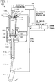
- FIG. 1 is a view showing an entire configuration of a uniflow scavenging two-cycle engine 100.
- the uniflow scavenging two-cycle engine 100 of the embodiment is used in a ship or the like.
- the uniflow scavenging two-cycle engine 100 is configured to include a cylinder 110, a piston 112, a crosshead 114, a connecting rod 116, a crankshaft 118, an exhaust port 120, an exhaust valve driving device 122, an exhaust valve 124, a scavenging port 126, a scavenging chamber 128, a first fuel supply unit 130, an auxiliary fuel supply unit 132, a main combustion chamber 134a, an auxiliary combustion chamber 134b, a second fuel supply unit 136, a rotary encoder 138, a governor 140 (speed regulator), a fuel supply control unit 142, and an exhaust control unit 144.
- a governor 140 speed regulator
- the piston 112 reciprocates in the cylinder 110 through four continuous strokes of intake (gas feeding), compression, combustion, and exhaust.
- One end of a piston rod 112a is fixed to the piston 112.
- the crosshead 114 is fixed to the other end of the piston rod 112a, and the crosshead 114 reciprocates along with the piston 112.
- a crosshead shoe 114a regulates movement of the crosshead 114 in a direction (rightward-leftward direction in FIG. 1 ) perpendicular to a stroke direction of the piston 112 (hereinafter, abbreviated to the stroke direction) in the cylinder 110.
- One end of the connecting rod 116 is rotatably supported in the crosshead 114.
- the other end of the connecting rod 116 is connected to the crankshaft 118 and the crankshaft 118 is structured to rotate with respect to the connecting rod 116.
- the exhaust port 120 is provided in a cylinder head 110a positioned on an upper side from a position of top dead center of the piston 112 in FIG. 1 .
- the exhaust port 120 is formed on the one end side (upper end side in FIG. 1 ) of the cylinder 110 in the stroke direction of the piston 112.
- the exhaust port 120 is opened and closed to discharge exhaust gas produced after combustion in the cylinder 110.
- the exhaust valve driving device 122 opens and closes the exhaust port 120 by causing the exhaust valve 124 to slide vertically at a predetermined timing. In this manner, the exhaust gas discharged via the exhaust port 120 is discharged to the outside, for example, after the exhaust gas is supplied to a turbine side of a supercharger (not shown).
- the scavenging port 126 is a hole penetrating from an inner circumferential surface (inner circumferential surface of a cylinder block 110b) to an outer circumferential surface of the cylinder 110 on the other end side (lower end side in FIG. 1 ) in the stroke direction of the piston 112, and a plurality of scavenging ports are provided all around the cylinder 110.
- the scavenging ports 126 suction active gas in the cylinder 110 in response to a sliding motion of the piston 112.
- the active gas contains an oxidizing agent such as oxygen or ozone, or a mixture thereof (for example, air).
- the active gas for example, air
- a compressor of the supercharger (not shown) is sealed in the scavenging chamber 128, and the active gas is suctioned from the scavenging port 126 due to differential pressure between the scavenging chamber 128 and the cylinder 110.
- the pressure in the scavenging chamber 128 can be substantially constant; however, a manometer may be provided in the scavenging port 126 in a case where the pressure in the scavenging chamber 128 changes, and other parameters such as an injection amount of the fuel gas according to a measurement value may be controlled.
- the first fuel supply unit 130 is disposed on the outer circumferential side in the cylinder 110 from the scavenging port 126, and causes the active gas and a premixture (fuel gas) to be suctioned from the scavenging port 126 into the cylinder 110 in the gas operation mode.
- the first fuel supply unit 130 will be described in detail with reference to FIGS. 2A and 2B .
- FIGS. 2A and 2B are views showing the first fuel supply unit 130
- FIG. 2A is an enlarged view showing the vicinity of the first fuel supply unit 130 of a side view of the cylinder 110.
- FIG. 2B is an enlarged view of a portion in a dashed line in FIG. 2A .
- the first fuel supply unit 130 has mixture pipes 130a and 130b which are separately formed from the cylinder 110.
- the mixture pipes 130a and 130b are annular members surrounding the cylinder 110 from the outside in the radial direction alomg a circumferential direction.
- the mixture pipe 130a is disposed on the one end side (upper side in FIG. 2A ) of the piston 112 from the scavenging port 126 in the stroke direction
- the mixture pipe 130b is disposed on the other end side (lower side in FIG. 2A ) of the piston 112 from the scavenging port 126 in the stroke direction.
- the mixture pipes 130a and 130b are provided with a mixture chamber that is formed in the inside thereof and extends to have an annular shape, and the fuel gas and the active gas are mixed in the mixture chamber such that the premixture is generated.
- a plurality of circulation pipes 130c that extend in the stroke direction of the piston 112 are disposed between the mixture pipes 130a and 130b in the circumferential direction of the mixture pipes 130a and 130b.
- one pipe communicates with the mixture pipe 130a, and the other pipe communicates with the mixture pipe 130b.
- the premixture from the mixture pipe 130a or the mixture pipe 130b is circulated in the circulation pipe 130c.
- the premixture When the first fuel injecting valve (not shown) is opened, the premixture is ejected from an injection opening 130d formed on the side surface of the circulation pipe 130c shown in FIG. 2B . As a result, the premixture is sprayed from the injection opening 130d of the first fuel supply unit 130 toward the active gas flowing toward the scavenging port 126 from the scavenging chamber 128.
- the premixture is simply referred to as the fuel gas except for a case where the premixture and the fuel gas are particularly distinguished.
- the auxiliary fuel supply unit 132 is an injection valve provided in the cylinder head 110a.
- the uniflow scavenging two-cycle engine 100 includes the main combustion chamber 134a and the auxiliary combustion chamber 134b, as the combustion chamber.
- the main combustion chamber 134a is surrounded by the cylinder head 110a, a cylinder liner in a cylinder block 110b, and the piston 112.
- the auxiliary combustion chamber 134b is formed inside the cylinder head 110a and has one end that projects from the cylinder head 110a toward the main combustion chamber 134a side.
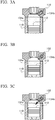
- FIGS. 3A to 3C are views for showing the auxiliary fuel supply unit 132.
- the second fuel supply unit 136 is omitted for easy understanding.
- the auxiliary fuel supply unit 132 has the front end that is opened to the auxiliary combustion chamber 134b, and the fuel oil is ejected toward the auxiliary combustion chamber 134b in the gas operating mode.
- the fuel oil ejected to the auxiliary combustion chamber 134b ignites with heat in the auxiliary combustion chamber 134b as shown in FIG. 3B .
- the fuel gas and the exhaust gas combusted in the auxiliary combustion chamber 134b is ejected along with flame to the main combustion chamber 134a, and the fuel gas suctioned into the cylinder 110 from the scavenging port 126 is combusted.
- the second fuel supply unit 136 is an ejecting valve provided in the cylinder head 110a, has the front end that is opened to the main combustion chamber 134a, and the fuel oil is injected toward the main combustion chamber 134a in the diesel operation mode.
- the fuel gas is supplied from the first fuel supply unit 130 into the cylinder 110 in the gas operation mode, and the fuel oil is supplied from the second fuel supply unit 136 into the cylinder 110 in the diesel operation mode.
- an appropriate compression ratio varies for the gas operation mode and the diesel operation mode.
- the gas operation mode is performed at the low compression ratio
- the diesel operation mode is performed at the high compression ratio.
- the gas operation mode is equivalent to the low compression ratio mode
- the diesel operation mode is equivalent to the high compression ratio mode.
- a variable compression ratio mechanism is provided in a connecting portion between the piston rod 112a and the crosshead 114 in order to make the compression ratio variable.
- FIGS. 4A and 4B are views showing the variable compression ratio mechanism 146, and show the connecting portion between the piston rod 112a and the crosshead 114. Since the gas operation mode is performed at the low compression ratio, as shown in FIG. 4A , the piston rod 112a and a crosshead pin 114b are directly connected to each other.
- variable compression ratio mechanism 146 is capable of reducing the volume of the main combustion chamber 134a at the top dead center so as to increase the compression ratio.
- the rotary encoder 138 is provided in the crankshaft 118 and an angle signal of the crankshaft (hereinafter, referred to as a crank angle signal) is detected.
- the governor 140 calculates a fuel injection amount, based on an engine output command value input from a higher control device and engine speed in response to a crank angle signal from the rotary encoder 138, and outputs the calculated amount to the fuel supply control unit 142.
- the fuel supply control unit 142 controls the first fuel supply unit 130 and the second fuel supply unit 136, based on information representing a fuel injection amount input from the governor 140, information representing the operation mode, and the crank angle signal from the rotary encoder 138.
- the exhaust control unit 144 outputs an exhaust valve operation signal to the exhaust valve driving device 122, based on information representing the fuel injection amount from the fuel supply control unit 142, information representing the operation mode, and the crank angle signal from the rotary encoder 138.
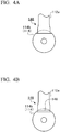
- FIGS. 5A to 5C are views showing the scavenging port 126
- FIG. 5A shows enlarged portion in the vicinity of the scavenging port 126 of a side view of the cylinder 110
- FIG. 5B is a sectional view taken along line IV(b)-IV(b) in FIG. 5A
- FIG. 5C is a sectional view taken along line IV(c) -IV(c) in FIG. 5A .
- the center of the piston 112 is represented by a dashed line in FIG. 5A .
- a swirling guide portion 126a is formed on one end side (upper side in FIG. 5A ) of the scavenging port 126 in the stroke direction from the center of the stroke direction.
- a center guide portion 126b is formed on the other end side (lower side in FIG. 5A ) in the stroke direction of the cylinder 110 from the swirling guide portion 126a.
- the swirling guide portion 126a has a shape that guides the scavenging gas from an outside to an inside of the cylinder 110 in a direction inclined with respect to a radial direction of the cylinder 110. Specifically, the swirling guide portion 126a extends in a direction inclined with respect to the radial direction of the cylinder 110. In addition, any scavenging port 126 provided over the entire circumference of the cylinder 110 is also inclined substantially to the equal extent that the swirling guide portion 126a is inclined. As a result, as shown with an arrow in FIG. 5B , the scavenging gas forms swirling flow, and rises in the cylinder 110 so as to flow to the exhaust port 120 side.
- the center guide portion 126b has a shape that guides the scavenging gas toward the center side of the cylinder 110 from the swirling guide portion 126a.
- the center guide portion 126b is an opening toward the center of the cylinder 110 and extends in the radial direction of the cylinder 110.
- the scavenging gas flows toward the center side of the cylinder 110 in the radial direction thereof, the scavenging gas rises in the cylinder 110 and flows to the exhaust port 120 side.
- the scavenging port 126 is a so-called skewed port. Operations performed and problems arising in the case where the scavenging port 126 is the skewed port are described with reference to FIGS. 6A and 6B .
- FIGS. 6A and 6B are views showing flow of scavenging gas in a comparative example.
- FIG. 6A shows flow of scavenging gas in a first comparative example
- FIG. 6B shows flow of scavenging gas in a second comparative example, in a state in which the piston 112 is positioned at the bottom dead center.
- a scavenging port S1 entirely becomes a swirling guide portion S1a
- a scavenging port S2 becomes a skewed port.
- the swirling flow is likely to be weaker than in the first comparative example due to the extent that the center guide portion S2b is provided.
- the swirling flow is weak in the second modification example, the scavenging efficiency is likely to be lowered.
- FIGS. 7A and 7B are views showing the flow of scavenging gas in the embodiment.
- FIG. 7A shows a state in which the piston 112 is positioned at the bottom dead center in the gas operation mode
- FIG. 7B shows a state in which the piston 112 is positioned at the bottom dead center in the diesel operation mode.
- the center guide portion 126b causes the scavenging gas to flow toward the center side of the cylinder 110 in the radial direction. Therefore, as shown with a dashed line in FIG. 7A , the speed distribution of the scavenging gas toward the exhaust port 120 side is more leveled than in the first comparative example, and the blow-by of the fuel gas are reduced.
- the position of the top dead center and the bottom dead center of the piston 112 are more shifted to the exhaust port 120 side than in the gas operation mode (low compression ratio mode).
- the center guide portion 126b has a positional relationship of facing the piston 112 (side wall of the piston 112) in the radial direction of the piston 112 by this shift. Therefore, the scavenging gas does not almost flow in the cylinder 110 from the center guide portion 126b, and the majority of scavenging gas flows in the cylinder 110 from the swirling guide portion 126a.
- the swirling flow becomes strong and the scavenging efficiency in improved.
- the center guide portion 126b may have a smaller area of facing the piston 112 in the low compression ratio mode than at least in the high compression ratio mode.
- the swirling guide portion 126a and the center guide portion 126b may individually form ports, or two ports may have a part in which the two ports are connected.
- the first fuel supply unit 130 ejects, from the injection opening 130d, the premixture obtained by mixing the fuel gas and the active gas, is described.
- the fuel gas may be injected from the injection opening 130d.
- the first fuel supply unit 130 is disposed on the outer circumferential side in the cylinder 110 from the scavenging port 126, and causes the fuel gas to be suctioned from the scavenging port 126 into the cylinder 110 is described.
- the first fuel supply unit 130 may be disposed at any position as long as the first fuel supply unit supplies the fuel gas into the cylinder 110.
- variable compression ratio mechanism 146 has the configuration in which the positions of the top dead center and the bottom dead center of the piston 112 are variable depending on the presence and absence of the shim plate 148 is described.
- another configuration such as a length of the piston 112 or the piston rod 112a may be hydraulically adjusted, may be employed.
- An example of the other configuration of the variable compression ratio mechanism will be described below in detail.
- the configuration in which the main combustion chamber 134a and the auxiliary combustion chamber 134b are provided as the combustion chamber, and the fuel gas combusted in the auxiliary combustion chamber 134b is injected into the main combustion chamber 134a in the gas operation mode, is described.
- a small amount of fuel oil may be injected in the main combustion chamber 134a to ignite the fuel gas suctioned from the scavenging port 126 without providing the auxiliary combustion chamber 134b.
- the fuel gas in the auxiliary combustion chamber 134b may ignite with a spark plug.
- variable compression ratio mechanism which can be applied to the present disclosure is described below in detail.
- a configuration of a four-cycle engine including a piston that is provided with a cylindrical piston outer having the sealed top surface, and a piston inner that is provided to freely slide inside the piston outer and is connected to a connecting rod via a piston pin in which a variable compression ratio mechanism is provided between the piston outer and the piston inner is disclosed (for example, see Japanese Unexamined Patent Application, First Publication No. 2005-54619 and Japanese Patent No. 4657162 ).
- variable compression ratio mechanism of the related art which is disclosed in the documents described above is configured to include a first rotary cam plate that is provided on the top surface of the piston inner and is configured to have a first projecting portion and a first recessed portion, a second rotary cam plate that is provided on a surface of the piston outer which faces the first rotary cam plate, and is configured to have a second recessed portion and a second projecting portion which mesh with the first projecting portion and the first recessed portion, and an actuator that causes the first rotary cam plate to rotate.
- the actuator is configured to include a hydraulic mechanism that causes the first rotary cam plate to rotate in one rotating direction, and a return spring that biases the first rotary cam plate in the other rotating direction; and a plunger of the hydraulic mechanism and the return spring are embedded in the piston inner.
- the hydraulic mechanism of the actuator causes the first rotary cam plate to rotate against a bias force of the return spring, thereby the first projecting portion and the second projecting portion come into contact with each other, a relative distance between the piston inner and the piston outer increases such that a high compression ratio is obtained. Furthermore, the first projecting portion and the first recessed portion are caused to mesh with the second recessed portion and the second projecting portion, and a relative distance between the piston inner and the piston outer decreases such that a low compression ratio is obtained.
- variable compression ratio mechanism since the actuator for causing the first rotary cam plate to rotate is embedded in the piston inner, a problem arises in that the piston has a complicated shape and thus manufacturing costs of the piston are likely to increase.
- variable compression ratio mechanism in which a compression ratio varies in a simplified structure and at low costs, is proposed as follows.
- variable compression ratio mechanism in an engine in which a piston slides in a cylinder due to explosion pressure produced in a combustion chamber, and the compression ratio varies by changing a position of a stroke of the piston.
- the variable compression ratio mechanism includes a first member that is provided with a plurality of tooth portions, which face a tooth surface thereof on the combustion chamber side, and which are provided on a circular circumference with the center axis of the piston as the axis, and that integrally reciprocates with the piston in a stroke direction of the piston, a second member that is provided with a plurality of meshing portions aligned on the same circular circumference with the tooth portions of the first member, that freely moves between a meshing position at which the meshing portions mesh with the tooth portions and a non-meshing position which is on the combustion chamber side from the meshing position and at which a meshing relationship between the meshing portions and the tooth portions is released, that freely rotates around the center axis of the piston at the non-meshing position, and that
- At least one of the contact portion and the contact target portion is configured of an inclined surface having an inclined angle in the rotating direction of the second member.
- the contact target portion may be provided with a plurality of tooth members facing the tooth surfaces on the combustion chamber side, on the circular circumference with the center axis of the piston as the axis, the contact portion may be provided with a plurality of meshing members disposed on the same circular circumference with the tooth members of the contact target portion, the meshing members may mesh with the tooth members, and the inclined surface may be provided on the tooth members and the meshing members.
- the driving unit causes the contact target portion to move in a direction in which the contact target portion approaches the combustion chamber, thereby, causing the contact target portion to come into contact with the contact portion, and causes the contact target portion to move in a direction in which the contact target portion is separated from the combustion chamber, thereby, causing the contact target portion to be separated from the contact portion.
- the contact portion is provided in the circumferential direction of the second member and the contact target portion is provided in the circumferential direction of the first member.
- the meshing portion of the second member has an apex, a first bottom portion that is positioned on the one side in the rotating direction of the second member with the apex as the boundary, and a second bottom portion that is positioned on the other side in the rotating direction of the second member with the apex as the boundary and has a larger depth from the apex than the first bottom portion.
- the distance between the apexes of the meshing members of the contact portion and the distance between the apexes of the tooth members of the contact target portion are longer than the distance between the apex of the meshing portion of the second member and the second bottom portion adjacent in the apex in the rotating direction, and is shorter than the distance between the first bottom portion and the second bottom portion in the rotating direction.
- the driving unit may cause the contact portion and the contact target portion to approach each other in the stroke direction such that both come into contact with each other, when the piston reaches the bottom dead center, and may cause the contact portion and the contact target portion to be separated from each other in the stroke direction after the pressing force is applied to the second member in the stroke direction via the contact portion.
- the engine may include a piston rod having one end fixed to the piston, and a crosshead that is connected to the other end side of the piston rod and integrally reciprocates with the piston.
- the first member and the second member may be provided in any one of the piston, the piston rod, or the crosshead.
- variable compression ratio mechanism described above will be described in detail with reference to the accompanying figures.
- the dimensions, materials, the specific numbers other than the dimensions and the materials, or the like is provided only as an example for easy understanding of the disclosure, and the disclosure is not limited thereto except for a case where a particular description is provided. Note that, in the following description, an element having substantially the same function and configuration is assigned with the same reference sign and a repeated description thereof is omitted, and illustration of an element without a direct relationship with the present disclosure is omitted in the figures.
- variable compression ratio mechanism a uniflow scavenging type of engine in which one period is constituted of two cycles (strokes) and gas flows in one direction inside the cylinder.
- the engine provided with the variable compression ratio mechanism is an engine in which the piston slides in the cylinder due to the explosion pressure produced in the combustion chamber, the number of cycles and the flowing direction of gas are not limited thereto.
- FIG. 8 is a view showing an entire configuration of a uniflow scavenging two-cycle engine 1100.
- the uniflow scavenging two-cycle engine 1100 of the embodiment is used in a ship or the like.
- the uniflow scavenging two-cycle engine 1100 of the embodiment is a so-called dual-fuel type engine, in which it is possible to execute by selecting one from the gas operation mode in which the fuel gas as the gaseous fuel is mainly combusted or the diesel operation mode in which fuel oil as the liquid fuel is combusted.
- the uniflow scavenging two-cycle engine 1100 is configured to include a cylinder 1110, a piston 1112, a crosshead 1114, a connecting rod 1116, a crankshaft 1118, an exhaust port 1120, an exhaust valve 1122, a scavenging port 1124, a scavenging reservoir 1126, a cooler 1128, a scavenging chamber 1130, and a combustion chamber 1132.
- exhaust, intake, compression, and combustion are performed during two strokes of an ascending stroke and a descending stroke of the piston 1112 and the piston 1112 reciprocates in the cylinder 1110.
- One end of a piston rod 1112a is fixed to the piston 1112.
- a crosshead pin 1114a of the crosshead 1114 is fixed to the other end of the piston rod 1112a, and the crosshead 1114 reciprocates along with the piston 1112.
- a crosshead shoe 1114b regulates movement of the crosshead 1114 in a direction (rightward-leftward direction in FIG. 8 ) perpendicular to a stroke direction of the piston 1112.
- the crosshead pin 1114a is inserted into a hole provided at one end of the connecting rod 1116, and supports the one end of the connecting rod 1116.
- the other end of the connecting rod 1116 is connected to the crankshaft 1118 and the crankshaft 1118 is structured to rotate with respect to the connecting rod 1116.
- the exhaust port 1120 is an opening provided in a cylinder head 1110a positioned above the top dead center of the piston 1112, and is opened and closed to discharge exhaust gas produced after combustion in the cylinder 1110.
- the exhaust valve 1122 slides vertically at a predetermined timing by an exhaust valve driving device (not shown) and opens and closes the exhaust port 1120. In this manner, the exhaust gas discharged via the exhaust port 1120 is discharged to the outside, for example, after the exhaust gas is supplied to a turbine side of a supercharger C via an exhaust pipe 1120a.
- the scavenging port 1124 is a hole penetrating from an inner circumferential surface (inner circumferential surface of a cylinder liner 1110b) to an outer circumferential surface of the cylinder 1110 on the lower end side, and a plurality of scavenging ports are provided all around the cylinder 1110.
- the scavenging ports 1124 suction active gas in the cylinder 1110 in response to a sliding motion of the piston 1112.
- the active gas contains an oxidizing agent such as oxygen or ozone, or a mixture thereof (for example, air).
- the active gas for example, air
- the active gas pressurized by a compressor of the supercharger C is sealed in the scavenging reservoir 1126, and the active gas is cooled by the cooler 1128.
- the cooled active gas is pressed into the scavenging chamber 1130 formed in a cylinder jacket 1110c.
- the active gas is suctioned from the scavenging port 1124 into the cylinder 1110 due to differential pressure between the scavenging chamber 1130 and the cylinder 1110.
- a pilot injection valve (not shown) is provided in the cylinder head 1110a.
- An appropriate amount of fuel oil is injected from the pilot injection valve at a predetermined time point in the engine cycle in the gas operation mode.
- the fuel oil is vaporized into fuel gas with heat in the combustion chamber 1132 surrounded by the cylinder head 1110a, the cylinder liner 1110b, and the piston 1112 and the fuel gas spontaneously ignites, is combusted in a short time, and the temperature of the combustion chamber 1132 rises to be very high.
- the piston 1112 reciprocates using expansion pressure mainly produced from the combustion of the fuel gas.
- the fuel gas is generated, for example, by gasifying liquefied natural gas (LNG).
- LNG gasifying liquefied natural gas
- the fuel gas is not limited to the LNG, and, for example, gas generated by gasifying liquefied petroleum gas (LPG), gas oil, heavy oil, or the like can be applied to the fuel gas.
- LPG gasifying liquefied petroleum gas
- LPG gas oil, heavy oil, or the like
- a larger amount of fuel oil is injected from the pilot injection valve in the diesel operation mode than an injection amount of the fuel oil in the gas operation mode.
- the piston 1112 reciprocates without using the fuel gas but using expansion pressure produced from the combustion of the fuel gas.
- variable compression ratio mechanism that changes the stroke positions of the piston 1112 and thereby changing the compression ratio.
- variable compression ratio mechanism will be described in detail.
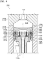
- FIG. 9 is a view showing a variable compression ratio mechanism 1200, and a sectional view showing the piston 1112 and the vicinity of the piston 1112.
- the piston 1112 of the embodiment is configured to include a first member 1210 connected to the piston rod 1112a by using a bolt 1112b, and a second member 1240 disposed on the combustion chamber 1132 side from the first member 1210.
- the variable compression ratio mechanism 1200 is configured to include the first member 1210, a press member 1220, the driving unit 1230, the second member 1240, and a press target member 1250.
- the first member 1210 has a cylindrical shape and is provided with tooth portions 1212 on a surface on the combustion chamber 1132 side.
- the first member 1210 is provided with an annular groove 1210a formed outwardly in the radial direction from the tooth portions 1212, and the press member 1220 is positioned in the annular groove 1210a so as to freely move in the stroke direction.
- the press member 1220 is provided with a contact target portion 1222 on a surface on the combustion chamber 1132 side.
- the driving unit 1230 is configured to include rods 1232 that communicate with the annular groove 1210a, are inserted into insertion holes 1210b formed at intervals in the circumferential direction of the annular groove 1210a, and are connected to a back surface of the contact target portion 1222 of the press member 1220, a spring 1234 that biases the rods 1232 to the second member 1240 side, and an actuator (for example, a hydraulic mechanism or a motor) not shown which presses the rods 1232 to the combustion chamber 1132 side.
- the driving unit causes the press member 1220 to move in the stroke direction. Note that a plurality of rods 1232 are connected to the press member 1220 and regulates the movement of the press member 1220 in the rotating direction.
- the second member 1240 has a cylindrical shape and is provided with meshing portions 1242 on a surface facing the first member 1210.
- the second member 1240 is provided with an annular groove 1240a formed outwardly in the radial direction from the meshing portions 1242, and the press target member 1250 is fitted into the annular groove 1240a.
- the press target member 1250 is fixed to the second member 1240 with a pin 1240b. Hence, the press target member 1250 moves along with the second member 1240.
- the press target member 1250 is provided with a contact portion 1252 on a surface on the first member 1210 side.
- the first member 1210 and the contact target portion 1222 move only in the stroke direction
- the second member 1240 and the contact portion 1252 move in the stroke direction, and moves around a center axis P of the piston 1112, which will be described below in detail.
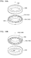
- FIGS. 10A, 10B , and 11A to 11F are views showing the first member 1210, the press member 1220, the second member 1240, and the press target member 1250.
- FIGS. 10A and 10B are perspective views showing a portion surrounded in a dashed line in FIG. 9 .
- FIG. 11A is a plan view showing the second member 1240 and the contact portion 1252 of the portion surrounded in the dashed line in FIG. 9 .
- FIG. 11B is a view showing the unrolled contact portion 1252 in a circumferential direction.
- FIG. 11C is a view showing the unrolled second member 1240 in the circumferential direction.
- FIG. 11D is a plan view showing the first member 1210 and the contact target portion 1222 in the portion surrounded in the dashed line in FIG. 9 .
- FIG. 11E is a view showing the unrolled first member 1210 in the circumferential direction.
- FIG. 11F is a view showing the unrolled contact target portion 1222 in the circumferential direction.
- the first member 1210 is provided with a plurality of tooth portions 1212 having a tooth surface on the combustion chamber 1132 (refer to FIG. 9 ) on the circular circumference with the center axis P of the piston 1112 (refer to FIG. 9 ) as the axis and reciprocates in the stroke direction.
- the tooth portion 1212 of the first member 1210 has an apex 1212a and a bottom portion 1212b which are disposed at equal intervals from each other in the rotating direction.
- the tooth portion 1212 of the first member 1210 is provided with an inclined surface 1212c that has an inclined angle in the circumferential direction (rotating direction of the second member 1240, hereinafter, simply referred to as a "rotating direction") with the center axis P as the axis, from the apex 1212a to the bottom portion 1212b, and an inclined surface 1212d that has an inclined angle from the bottom portion 1212b to the apex 1212a in the rotating direction.
- the heights of the tooth portions 1212 of the first member 1210 are all the same.
- the second member 1240 has a plurality of meshing portions 1242 aligned in the same circular circumference with the tooth portions 1212 of the first member 1210.
- the meshing portion 1242 has an apex 1242a, and bottom portions 1242b and 1242c which have different depths from the apex 1242a in the stroke direction. Specifically, the depth from the apex 1242a to the bottom portion 1242b (second bottom portion) in the rotating direction is larger by a width D than a depth from the apex 1242a to the bottom portion 1242c (first bottom portion).
- the meshing portions 1242 of the second member 1240 are aligned such that the bottom portion 1242b and the bottom portion 1242c are alternately disposed to interpose the apex 1242a therebetween.
- the meshing portion 1242 of the second member 1240 is provided with an inclined surface 1242d that has an inclined angle in the rotating direction from the apex 1242a to the bottom portion 1242b, an inclined surface 1242e that has an inclined angle in the rotating direction from the bottom portion 1242b to the apex 1242a, an inclined surface 1242f that has an inclined angle in the rotating direction from the apex 1242a to the bottom portion 1242c, and an inclined surface 1242g that has an inclined angle in the rotating direction from the bottom portion 1242c to the apex 1242a.
- the second member 1240 freely moves between a meshing position at which the meshing portions 1242 and the tooth portions 1212 mesh each other and a non-meshing position which is on the combustion chamber 1132 side from the meshing position and at which a meshing relationship between the meshing portions 1242 and the tooth portions 1212 is released, and freely rotates around the center axis P of the piston 1112 at the non-meshing position, which will be described below in detail.
- the apexes 1212a of the tooth portions 1212 mesh with the bottom portions 1242b of the meshing portions 1242, or the apexes 1212a of the tooth portions 1212 mesh with the bottom portions 1242c of the meshing portions 1242, depending on the relative rotating position with respect to the first member 1210.
- depths of meshing between the tooth portions 1212 and the meshing portions 1242 are different depending on a relative rotating position of the second member 1240 and the first member 1210.
- the contact target portion 1222 is configured to have the plurality of tooth members 1224 provided in the circumferential direction of the first member 1210 and the tooth member 1224 has a tooth surface on the combustion chamber 1132 (refer to FIG. 9 ) side.
- the contact target portion 1222 is provided in the press member 1220 so as to freely move with respect to the first member 1210, and moves in the stroke direction in response to the press member 1220 by the driving unit 1230.
- the tooth members 1224 of the contact target portion 1222 are disposed such that the apexes 1224a are disposed at equal intervals in the rotating direction, that is, the bottom portions 1224b are disposed at equal intervals in the rotating direction.
- the tooth member 1224 of the contact target portion 1222 is provided with an inclined surface 1224c that has an inclined angle in the rotating direction from the apex 1224a to the bottom portion 1224b and a perpendicular surface 1224d that stands upright from the bottom portion 1224b to the apex 1224a.
- the contact portion 1252 is configured to have the plurality of meshing members 1254 provided in the second member 1240 in the circumferential direction of the second member 1240 and are aligned on the same circular circumference with the tooth members 1224 of the contact target portion 1222, and the meshing members 1254 mesh with the tooth members 1224.
- the contact portion 1252 is provided on the press target member 1250, and the press target member 1250 is fixed to the second member 1240 with the pin 1240b. Therefore, the contact portion 1252 integrally rotates with the second member 1240 or integrally reciprocates with the second member 1240 in the stroke direction.
- the meshing members 1254 of the contact portion 1252 are disposed such that the apexes 1254a are disposed at equal intervals in the rotating direction, that is, the bottom portions 1254b are disposed at equal intervals in the rotating direction.
- the meshing member 1254 of the contact portion 1252 is provided with an inclined surface 1254c that has an inclined angle in the rotating direction from the apex 1254a to the bottom portion 1254b and a perpendicular surface 1254d that stands upright from the bottom portion 1254b to the apex 1254a.
- FIG. 12 is a view showing the dimensional relationship between the tooth portion 1212 of the first member 1210, the tooth member 1224 of the contact target portion 1222, the meshing portion 1242 of the second member 1240, and the meshing member 1254 of the contact portion 1252. As shown in FIG.
- a distance (rotating angle) between the apexes 1254a of the contact portion 1252 in the rotating direction that is, a distance (rotating angle) between the apexes 1224a of the contact target portion 1222 in the rotating direction
- a distance L1 the distance (rotating angle) between the apexes 1242a of the second member 1240 and the bottom portion 1242b adjacent to the apex 1242a in the rotating direction
- a distance L2 a distance (rotating angle) between the bottom portion 1242b and the bottom portion 1242c of the second member 1240 in the rotating direction
- a distance (rotating angle) between the bottom portions 1242b in the rotating direction and a distance (rotating angle) between the bottom portions 1242c in the rotating direction is referred to as a distance L4.
- the contact target portion 1222, the second member 1240 and the contact portion 1252 are disposed such that the distance L1 is longer than the distance L2, and is shorter than the distance L3.
- the first member 1210 is disposed such that the distance between the apexes 1212a becomes the distance L4.
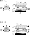
- FIGS. 13A to 13C and 14A and 14B are views showing changes in compression ratio by the variable compression ratio mechanism 1200.
- the first member 1210, the contact target portion 1222, the second member 1240, and the contact portion 1252 are shown in a simplified manner, and the driving unit 1230 is omitted in FIGS. 13A to 13C and 14A and 14B .
- the first member 1210 and the second member 1240 are represented by hatched regions
- the contact target portion 1222 is represented by a black region
- the contact portion 1252 is represented by a white region.
- movement in the stroke direction is represented by a white arrow
- the movement in the rotating direction is represented by a black arrow in FIGS. 13A to 13C , 14A, and 14B .
- the contact portion 1252 and the contact target portion 1222 are separated in the stroke direction as shown in FIG. 13A .
- the apexes 1212a of the first members 1210 mesh with the bottom portions 1242b of the second member 1240.
- the apexes 1254a of the contact portion 1252 and the bottom portions 1224b of the contact target portion 1222 are disposed at different positions from each other in the circumferential direction.
- the apexes 1224a of the contact target portion 1222 have a positional relationship of facing the inclined surface 1254c of the contact portion 1252.
- the driving unit 1230 causes the contact target portion 1222 (press member 1220) to move in the stroke direction toward the contact portion 1252 (press target member 1250) side (direction of approaching to the combustion chamber 1132), and causes the contact target portion 1222 to come into contact with the contact portion 1252 as shown in FIG. 13B , and the pressing force is applied to the second member 1240 via the contact portion 1252.
- the apex 1224a of the contact target portion 1222 has a positional relationship to face the inclined surface 1254c of the contact portion 1252, the press force generated by the driving unit 1230 is distributed on the inclined surface 1254c in the stroke direction and the rotating direction and is transported to the second member 1240.
- the apexes 1212a of the first member 1210 mesh with the bottom portions 1242b of the second member 1240 at the meshing position shown in FIG. 13A , and the positional relationship in which the apexes 1212a of the first member 1210 and the inclined surface 1242e or the inclined surface 1242g (here, the inclined surfaces 1242g) of the second member 1240 face each other, is achieved at the non-meshing position shown in FIG. 13C .
- the driving unit 1230 causes the contact target portion 1222 (press member 1220) to move in a direction in which the contact target portion is separated from the combustion chamber 1132 such that the contact portion 1252 and the contact target portion 1222 are separated in the stroke direction.
- the contact target portion 1222 is caused to move in the direction in which the contact target portion 1222 is separated from the combustion chamber 1132, and thereby the second member 1240 and the contact portion 1252 move on the first member 1210 side.
- the force from the combustion chamber 1132 to the crankshaft 1118 is applied to the inclined surface 1212c of the first member 1210 and the inclined surface 1242e of the second member 1240 in the rotating direction when the second member 1240 comes into contact with the first member 1210.
- the second member 1240 further rotate in a process of meshing with the first member 1210, and moves to the meshing position at which the apexes 1212a of the first member 1210 mesh with the bottom portions 1242c of the second member 1240.
- the contact portion 1252 rotates in response to the rotation of the second member 1240, and thereby the positional relationship, that is, practically the same positional relationship as shown in FIG. 13A , in which the apexes 1224a of the tooth members 1224 of the contact target portion 1222 face the inclined surface 1254c of the meshing members 1254 of the contact portion 1252 is again achieved.
- FIGS. 15A and 15B are views showing a positional relationship between the first member 1210 and the second member 1240 which have different meshing positions, respectively.
- FIG. 15A is a perspective view of the first member 1210 and the second member 1240 at the meshing position shown in FIG. 13A
- FIG. 15B is a perspective view of the first member 1210 and the second member 1240 at the meshing position shown in FIG. 14B .
- the driving unit 1230 causes the contact target portion 1222 (press member 1220) to move in an approach direction to the combustion chamber 1132 and to come into contact with the contact portion 1252, and the pressing force is applied to the second member 1240 via the contact portion 1252 in the stroke direction. Then, the driving unit causes the contact portion 1252 to move in a separated direction from the combustion chamber 1132 such that the contact portion 1252 and the contact target portion 1222 are separated from each other in the stroke direction, and thereby the apex 1212a of the first member 1210 shift from the meshing position (refer to FIGS. 13A and 15A ) at which the apexes mesh with the bottom portions 1242b of the second member 1240 to the meshing position (refer to FIGS.
- a height H of the first member 1210 and the second member 1240 increases by a width D as a difference in depth of the bottom portion 1242c from the apex 1242a.
- the first member 1210 projects from the second member 1240 to the combustion chamber 1132 side by the width D as the difference in depth of the bottom portion 1242b and the bottom portion 1242c from the apex 1242a.
- the stroke position of the piston 1112 changes and it is possible to change the compression ratio from the low compression ratio to the high compression ratio.
- variable compression ratio mechanism 1200 As described above, in the variable compression ratio mechanism 1200 according to the embodiment, only the contact target portion 1222 is pressed in the stroke direction, and then it is possible to rotate the second member 1240. Therefore, the actuator for rotating the second member 1240 does not need to be embedded in the piston 1112, and thus it is possible to simplify the shape of the piston 1112. As described above, it is possible to reduce an increase in the manufacturing costs of the piston 1112.
- the shear force does not act in the rotating direction while the tooth portions 1212 of the first member 1210 mesh with the meshing portions 1242 of the second member 1240.
- the first member 1210 and the meshing portions 1242 may not have very high stiffness such that it is possible to reduce an increase in costs of materials.
- variable compression ratio mechanism 1200 of the embodiment has only a simple configuration in which the contact target portion 1222 is pressed or the pressing is released, it is possible to separate the first member 1210 from the second member 1240, and to perform rotation of the second member 1240. Therefore, it is possible to change the compression ratio of not only the uniflow scavenging two-cycle engine 1100, but also a four-cycle engine. Note that, the four-cycle engine has not only a period when the force is applied from the combustion chamber 1132 to the crankshaft 1118, but also a period when the force is applied from the crankshaft 1118 to the combustion chamber 1132.
- variable compression ratio mechanism 1200 of the embodiment is applied to the four-cycle engine
- a structure in which the first member 1210 is not separated from the second member 1240 may be employed.
- the first member 1210 may be biased to the second member 1240 with an elastic member such as a spring.
- the driving unit 1230 causes the contact portion 1252 to approach the contact target portion 1222 such that both come into contact with each other, and causes the contact portion 1252 to be separated from the contact target portion 1222 in the stroke direction after the pressing force is applied to the second member 1240 in the stroke direction via the contact portion 1252.
- the pressing force from the driving unit 1230 to the contact target portion 1222 can be minimized.
- the compression ratio is changed when the piston 1112 reaches the bottom dead center, and thereby it is possible to reduce the driving force of the driving unit 1230 and it is possible to reduce operation costs of the driving unit 1230.
- variable compression ratio mechanism 1200 may change the compression ratio depending on the operation mode or may change the compression ratio depending on a load of the engine.
- the dimensional relationship between the tooth portion 1212 of the first member 1210, the tooth member 1224 of the contact target portion 1222, the meshing portion 1242 of the second member 1240, and the meshing member 1254 of the contact portion 1252 is set as described above, and thereby it is possible to cause the contact portion 1252 (second member 1240) not only to rotate with the pressing force of the contact target portion 1222 shown in FIG. 13C , but also to cause the second member 1240 (contact portion 1252) to further rotate, as shown in FIG. 14A .
- the additional rotation makes it possible to maintain the constant relative positional relationship between the first member 1210 and the second member 1240 at all times.
- the contact target portion 1222 presses the contact portion 1252 it is possible to shift, by one tooth, a position at which the tooth portions 1212 of the first member 1210 meshes with the meshing portions 1242 of the second member 1240.
- the second member 1240 of the embodiment have the bottom portions 1242b and 1242c which are alternately provided, that is, the meshing depths of the first member 1210 and the second member 1240 are alternately different by one tooth at the meshing position, it is possible to change the meshing position with the pressing by the contact target portion 1222 once.
- variable compression ratio mechanism 1200 that is capable of changing the compression ratio in two steps is described above.
- variable compression ratio mechanism it is possible to change the compression ratio in three or more steps, by devising the tooth portion of the first member and the meshing portion of the second member.
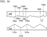
- FIG. 16 is a view showing a second member 1340 of the variable compression ratio mechanism 1200 according to a modification example.
- the meshing portion 1342 of the second member 1340 is configured to have four apexes 1342b, 1342d, 1342f, and 1342h, and four bottom portions 1342a, 1342c, 1342e, and 1342g, which have different depths from the apex 1342b disposed to be closest to the first member 1210 side.
- the distance L1 between the apexes 1254a of the contact portion 1252 in the rotating direction may be determined, based on the longest distance of a distance L5 between the bottom portion 1342g and the apex 1342h in the rotating direction, that is, the distance between the bottom portion and the apex of the meshing portion 1342 of the second member 1340 in the rotating direction.
- the driving unit 1230 may cause the contact portion 1252 and the contact target portion 1222 to approach each other in the stroke direction such that both come into contact with each other, and may cause the contact portion 1252 and the contact target portion 1222 to be separated from each other in the stroke direction after the pressing force is applied to the second member 1240 in the stroke direction via the contact portion 1252.
- the driving unit 1230 may cause the contact portion 1252 to move or may cause the contact portion 1252 and the contact target portion 1222 to move.
- the contact target portion 1222 may be provided in the circumferential direction of the first member 1210.
- the contact target portion 1222 may be provided inwardly in the radial direction from the tooth portion 1212 of the first member 1210.
- the contact portion 1252 may be provided in the circumferential direction of the second member 1240.
- the contact portion 1252 may be provided inwardly in the radial direction from the meshing portion 1242 of the second member 1240.
- the apexes 1242a of the second member 1240 may have a constant height, the depths of the bottom portions 1212b of the first member 1210 may be caused to be different from each other, and thereby the meshing depths between the tooth portions 1212 and the meshing portions 1242 may be caused to be different from each other is described.
- the driving unit 1230 causes the contact portion 1252 and the contact target portion 1222 to come into contact with each other in a state in which second member 1240 is disposed at the meshing position
- the second member 1240 moves from the meshing position to the non-meshing position with the pressing force in the stroke direction, and the second member 1240 rotates with the component force applied in the rotating direction such that the relative rotating position with respect to the first member 1210 changes, when the meshing relationship between the tooth portion 1212 and the meshing portion 1242 is released.
- the inclined surface having the inclined angle in the rotating direction of the second member 1240 may be provided at least one of the contact portion 1252 and the contact target portion 1222.
- first member 1210 and the second member 1240 of the variable compression ratio mechanism 1200 are provided in the piston 1112
- first member 1210 and the second member 1240 may be provided in the piston rod 1112a or the crosshead 1114.
- the present disclosure can use an engine in which a compression ratio is variable.
Landscapes
- Engineering & Computer Science (AREA)
- Chemical & Material Sciences (AREA)
- Combustion & Propulsion (AREA)
- Mechanical Engineering (AREA)
- General Engineering & Computer Science (AREA)
- Oil, Petroleum & Natural Gas (AREA)
- Output Control And Ontrol Of Special Type Engine (AREA)
Applications Claiming Priority (3)
| Application Number | Priority Date | Filing Date | Title |
|---|---|---|---|
| JP2014221345A JP6633270B2 (ja) | 2014-10-30 | 2014-10-30 | ユニフロー掃気式2サイクルエンジン |
| JP2014224453A JP6413655B2 (ja) | 2014-11-04 | 2014-11-04 | 圧縮比可変機構 |
| PCT/JP2015/080235 WO2016068128A1 (ja) | 2014-10-30 | 2015-10-27 | ユニフロー掃気式2サイクルエンジン |
Publications (3)
| Publication Number | Publication Date |
|---|---|
| EP3214292A1 EP3214292A1 (en) | 2017-09-06 |
| EP3214292A4 EP3214292A4 (en) | 2018-08-29 |
| EP3214292B1 true EP3214292B1 (en) | 2019-09-25 |
Family
ID=55857464
Family Applications (1)
| Application Number | Title | Priority Date | Filing Date |
|---|---|---|---|
| EP15855899.9A Active EP3214292B1 (en) | 2014-10-30 | 2015-10-27 | Uniflow scavenging two-cycle engine |
Country Status (6)
| Country | Link |
|---|---|
| US (1) | US10371042B2 (da) |
| EP (1) | EP3214292B1 (da) |
| KR (1) | KR101901428B1 (da) |
| CN (1) | CN107110034B (da) |
| DK (1) | DK3214292T3 (da) |
| WO (1) | WO2016068128A1 (da) |
Families Citing this family (3)
| Publication number | Priority date | Publication date | Assignee | Title |
|---|---|---|---|---|
| JP6946977B2 (ja) * | 2017-11-28 | 2021-10-13 | 株式会社Ihi | 可変圧縮装置及びエンジンシステム |
| JP2019157845A (ja) | 2018-03-16 | 2019-09-19 | 株式会社ディーゼルユナイテッド | 舶用エンジン |
| DK180375B1 (en) * | 2019-07-11 | 2021-02-12 | Man Energy Solutions Filial Af Man Energy Solutions Se Tyskland | Internal combustion engine |
Family Cites Families (22)
| Publication number | Priority date | Publication date | Assignee | Title |
|---|---|---|---|---|
| US3144749A (en) * | 1956-11-26 | 1964-08-18 | Miller Ralph | Two cycle supercharged difsel engine |
| US3309865A (en) * | 1965-04-01 | 1967-03-21 | Worthington Corp | Internal combustion engine |
| US3905340A (en) * | 1972-08-22 | 1975-09-16 | Performance Industries | Engine valving and porting |
| US4635590A (en) * | 1983-04-28 | 1987-01-13 | Anthony Gerace | Internal combustion engine and operating cycle therefor |
| JPS6056120A (ja) * | 1983-09-08 | 1985-04-01 | Mitsubishi Heavy Ind Ltd | シリンダライナ |
| US4827882A (en) * | 1985-07-16 | 1989-05-09 | Paul Marius A | Internal regenerative combustion engines with thermal integrated optimized system |
| JPH0226700A (ja) | 1988-07-13 | 1990-01-29 | Kubota Ltd | 汚泥の濃縮前処理方法 |
| JP3966742B2 (ja) | 2001-06-15 | 2007-08-29 | 本田技研工業株式会社 | 内燃機関の圧縮比可変装置 |
| US7469664B2 (en) * | 2003-06-25 | 2008-12-30 | Advanced Propulsion Technologies, Inc. | Internal combustion engine |
| JP4084718B2 (ja) * | 2003-07-31 | 2008-04-30 | 本田技研工業株式会社 | 内燃機関の圧縮比可変装置 |
| JP2006183482A (ja) * | 2004-12-27 | 2006-07-13 | Nissan Motor Co Ltd | 2ストローク内燃機関 |
| JP4395474B2 (ja) | 2005-11-18 | 2010-01-06 | 三菱重工業株式会社 | 掃気管制弁装置を備えた内燃機関 |
| JP4657162B2 (ja) * | 2006-07-10 | 2011-03-23 | 本田技研工業株式会社 | 内燃機関の圧縮比可変装置 |
| US9228491B2 (en) * | 2009-08-04 | 2016-01-05 | Jack R. Taylor | Two-stroke uniflow turbo-compound internal combustion engine |
| US8561581B2 (en) * | 2009-08-04 | 2013-10-22 | Jack R. Taylor | Two-stroke uniflow turbo-compound internal combustion engine |
| EP2655827A4 (en) * | 2010-12-14 | 2017-07-12 | Jack R. Taylor | Full expansion internal combustion engine |
| JP5395848B2 (ja) * | 2011-06-24 | 2014-01-22 | 三井造船株式会社 | 低速2サイクルガスエンジン |
| JP5707274B2 (ja) * | 2011-08-12 | 2015-04-22 | 株式会社Ihi | 2サイクルエンジン |
| CN103541819B (zh) * | 2012-07-17 | 2017-08-08 | 瓦锡兰瑞士公司 | 大型往复活塞式燃烧发动机及其控制设备和控制方法 |
| JP6115045B2 (ja) | 2012-08-31 | 2017-04-19 | 株式会社Ihi | ユニフロー掃気式2サイクルエンジン |
| JP6075086B2 (ja) * | 2013-01-28 | 2017-02-08 | 株式会社Ihi | ユニフロー掃気式2サイクルエンジンおよびユニフロー掃気式2サイクルエンジンの燃料噴射方法 |
| EP2801713A1 (en) * | 2013-05-07 | 2014-11-12 | Wärtsilä Schweiz AG | A Reciprocating Piston Combustion Engine and an Apparatus and a Method for Controlling Such an Engine |
-
2015
- 2015-10-27 CN CN201580057782.5A patent/CN107110034B/zh active Active
- 2015-10-27 WO PCT/JP2015/080235 patent/WO2016068128A1/ja not_active Ceased
- 2015-10-27 EP EP15855899.9A patent/EP3214292B1/en active Active
- 2015-10-27 KR KR1020177005077A patent/KR101901428B1/ko active Active
- 2015-10-27 DK DK15855899.9T patent/DK3214292T3/da active
-
2017
- 2017-03-06 US US15/450,227 patent/US10371042B2/en active Active
Non-Patent Citations (1)
| Title |
|---|
| None * |
Also Published As
| Publication number | Publication date |
|---|---|
| EP3214292A4 (en) | 2018-08-29 |
| WO2016068128A1 (ja) | 2016-05-06 |
| KR101901428B1 (ko) | 2018-09-21 |
| US10371042B2 (en) | 2019-08-06 |
| CN107110034A (zh) | 2017-08-29 |
| KR20170031777A (ko) | 2017-03-21 |
| EP3214292A1 (en) | 2017-09-06 |
| US20170175616A1 (en) | 2017-06-22 |
| CN107110034B (zh) | 2020-03-03 |
| DK3214292T3 (da) | 2020-01-06 |
Similar Documents
| Publication | Publication Date | Title |
|---|---|---|
| CN104854323B (zh) | 单流扫气式二冲程发动机和单流扫气式二冲程发动机的燃料喷射方法 | |
| KR101799956B1 (ko) | 엔진 | |
| EP3098416B1 (en) | Crosshead engine | |
| EP2602460B1 (en) | Two-stroke engine | |
| JP6115045B2 (ja) | ユニフロー掃気式2サイクルエンジン | |
| CN104685188A (zh) | 单流扫气式二冲程发动机 | |
| KR101712179B1 (ko) | 유니플로 소기식 2사이클 엔진 | |
| EP3214292B1 (en) | Uniflow scavenging two-cycle engine | |
| US11098620B2 (en) | Variable compression ratio mechanism | |
| KR102401934B1 (ko) | 압축비 가변 기구 | |
| JP6633270B2 (ja) | ユニフロー掃気式2サイクルエンジン | |
| EP3217009B1 (en) | Uniflow scavenging two-cycle engine | |
| JP2019120185A (ja) | シリンダーの周壁面構造 | |
| JP2016089701A (ja) | 圧縮比可変機構 |
Legal Events
| Date | Code | Title | Description |
|---|---|---|---|
| STAA | Information on the status of an ep patent application or granted ep patent |
Free format text: STATUS: THE INTERNATIONAL PUBLICATION HAS BEEN MADE |
|
| PUAI | Public reference made under article 153(3) epc to a published international application that has entered the european phase |
Free format text: ORIGINAL CODE: 0009012 |
|
| STAA | Information on the status of an ep patent application or granted ep patent |
Free format text: STATUS: REQUEST FOR EXAMINATION WAS MADE |
|
| 17P | Request for examination filed |
Effective date: 20170309 |
|
| AK | Designated contracting states |
Kind code of ref document: A1 Designated state(s): AL AT BE BG CH CY CZ DE DK EE ES FI FR GB GR HR HU IE IS IT LI LT LU LV MC MK MT NL NO PL PT RO RS SE SI SK SM TR |
|
| AX | Request for extension of the european patent |
Extension state: BA ME |
|
| DAV | Request for validation of the european patent (deleted) | ||
| DAX | Request for extension of the european patent (deleted) | ||
| A4 | Supplementary search report drawn up and despatched |
Effective date: 20180731 |
|
| RIC1 | Information provided on ipc code assigned before grant |
Ipc: F02B 43/02 20060101ALI20180725BHEP Ipc: F02B 25/06 20060101ALI20180725BHEP Ipc: F02D 15/02 20060101AFI20180725BHEP Ipc: F02B 31/00 20060101ALI20180725BHEP Ipc: F02B 23/10 20060101ALI20180725BHEP Ipc: F02D 19/06 20060101ALI20180725BHEP Ipc: F02B 75/04 20060101ALI20180725BHEP Ipc: F02D 19/10 20060101ALI20180725BHEP Ipc: F02B 25/04 20060101ALI20180725BHEP |
|
| GRAP | Despatch of communication of intention to grant a patent |
Free format text: ORIGINAL CODE: EPIDOSNIGR1 |
|
| STAA | Information on the status of an ep patent application or granted ep patent |
Free format text: STATUS: GRANT OF PATENT IS INTENDED |
|
| INTG | Intention to grant announced |
Effective date: 20190408 |
|
| GRAS | Grant fee paid |
Free format text: ORIGINAL CODE: EPIDOSNIGR3 |
|
| GRAA | (expected) grant |
Free format text: ORIGINAL CODE: 0009210 |
|
| STAA | Information on the status of an ep patent application or granted ep patent |
Free format text: STATUS: THE PATENT HAS BEEN GRANTED |
|
| AK | Designated contracting states |
Kind code of ref document: B1 Designated state(s): AL AT BE BG CH CY CZ DE DK EE ES FI FR GB GR HR HU IE IS IT LI LT LU LV MC MK MT NL NO PL PT RO RS SE SI SK SM TR |
|
| REG | Reference to a national code |
Ref country code: GB Ref legal event code: FG4D |
|
| REG | Reference to a national code |
Ref country code: CH Ref legal event code: EP |
|
| REG | Reference to a national code |
Ref country code: DE Ref legal event code: R096 Ref document number: 602015038822 Country of ref document: DE |
|
| REG | Reference to a national code |
Ref country code: CH Ref legal event code: NV Representative=s name: NOVAGRAAF INTERNATIONAL SA, CH Ref country code: AT Ref legal event code: REF Ref document number: 1184052 Country of ref document: AT Kind code of ref document: T Effective date: 20191015 |
|
| REG | Reference to a national code |
Ref country code: IE Ref legal event code: FG4D |
|
| REG | Reference to a national code |
Ref country code: DK Ref legal event code: T3 Effective date: 20191219 |
|
| REG | Reference to a national code |
Ref country code: NL Ref legal event code: MP Effective date: 20190925 |
|
| PG25 | Lapsed in a contracting state [announced via postgrant information from national office to epo] |
Ref country code: SE Free format text: LAPSE BECAUSE OF FAILURE TO SUBMIT A TRANSLATION OF THE DESCRIPTION OR TO PAY THE FEE WITHIN THE PRESCRIBED TIME-LIMIT Effective date: 20190925 Ref country code: HR Free format text: LAPSE BECAUSE OF FAILURE TO SUBMIT A TRANSLATION OF THE DESCRIPTION OR TO PAY THE FEE WITHIN THE PRESCRIBED TIME-LIMIT Effective date: 20190925 Ref country code: LT Free format text: LAPSE BECAUSE OF FAILURE TO SUBMIT A TRANSLATION OF THE DESCRIPTION OR TO PAY THE FEE WITHIN THE PRESCRIBED TIME-LIMIT Effective date: 20190925 Ref country code: FI Free format text: LAPSE BECAUSE OF FAILURE TO SUBMIT A TRANSLATION OF THE DESCRIPTION OR TO PAY THE FEE WITHIN THE PRESCRIBED TIME-LIMIT Effective date: 20190925 Ref country code: BG Free format text: LAPSE BECAUSE OF FAILURE TO SUBMIT A TRANSLATION OF THE DESCRIPTION OR TO PAY THE FEE WITHIN THE PRESCRIBED TIME-LIMIT Effective date: 20191225 Ref country code: NO Free format text: LAPSE BECAUSE OF FAILURE TO SUBMIT A TRANSLATION OF THE DESCRIPTION OR TO PAY THE FEE WITHIN THE PRESCRIBED TIME-LIMIT Effective date: 20191225 |
|
| REG | Reference to a national code |
Ref country code: LT Ref legal event code: MG4D |
|
| PG25 | Lapsed in a contracting state [announced via postgrant information from national office to epo] |
Ref country code: LV Free format text: LAPSE BECAUSE OF FAILURE TO SUBMIT A TRANSLATION OF THE DESCRIPTION OR TO PAY THE FEE WITHIN THE PRESCRIBED TIME-LIMIT Effective date: 20190925 Ref country code: RS Free format text: LAPSE BECAUSE OF FAILURE TO SUBMIT A TRANSLATION OF THE DESCRIPTION OR TO PAY THE FEE WITHIN THE PRESCRIBED TIME-LIMIT Effective date: 20190925 Ref country code: GR Free format text: LAPSE BECAUSE OF FAILURE TO SUBMIT A TRANSLATION OF THE DESCRIPTION OR TO PAY THE FEE WITHIN THE PRESCRIBED TIME-LIMIT Effective date: 20191226 |
|
| REG | Reference to a national code |
Ref country code: AT Ref legal event code: MK05 Ref document number: 1184052 Country of ref document: AT Kind code of ref document: T Effective date: 20190925 |
|
| PG25 | Lapsed in a contracting state [announced via postgrant information from national office to epo] |
Ref country code: PT Free format text: LAPSE BECAUSE OF FAILURE TO SUBMIT A TRANSLATION OF THE DESCRIPTION OR TO PAY THE FEE WITHIN THE PRESCRIBED TIME-LIMIT Effective date: 20200127 Ref country code: IT Free format text: LAPSE BECAUSE OF FAILURE TO SUBMIT A TRANSLATION OF THE DESCRIPTION OR TO PAY THE FEE WITHIN THE PRESCRIBED TIME-LIMIT Effective date: 20190925 Ref country code: ES Free format text: LAPSE BECAUSE OF FAILURE TO SUBMIT A TRANSLATION OF THE DESCRIPTION OR TO PAY THE FEE WITHIN THE PRESCRIBED TIME-LIMIT Effective date: 20190925 Ref country code: RO Free format text: LAPSE BECAUSE OF FAILURE TO SUBMIT A TRANSLATION OF THE DESCRIPTION OR TO PAY THE FEE WITHIN THE PRESCRIBED TIME-LIMIT Effective date: 20190925 Ref country code: NL Free format text: LAPSE BECAUSE OF FAILURE TO SUBMIT A TRANSLATION OF THE DESCRIPTION OR TO PAY THE FEE WITHIN THE PRESCRIBED TIME-LIMIT Effective date: 20190925 Ref country code: PL Free format text: LAPSE BECAUSE OF FAILURE TO SUBMIT A TRANSLATION OF THE DESCRIPTION OR TO PAY THE FEE WITHIN THE PRESCRIBED TIME-LIMIT Effective date: 20190925 Ref country code: EE Free format text: LAPSE BECAUSE OF FAILURE TO SUBMIT A TRANSLATION OF THE DESCRIPTION OR TO PAY THE FEE WITHIN THE PRESCRIBED TIME-LIMIT Effective date: 20190925 Ref country code: AT Free format text: LAPSE BECAUSE OF FAILURE TO SUBMIT A TRANSLATION OF THE DESCRIPTION OR TO PAY THE FEE WITHIN THE PRESCRIBED TIME-LIMIT Effective date: 20190925 Ref country code: AL Free format text: LAPSE BECAUSE OF FAILURE TO SUBMIT A TRANSLATION OF THE DESCRIPTION OR TO PAY THE FEE WITHIN THE PRESCRIBED TIME-LIMIT Effective date: 20190925 |
|
| PG25 | Lapsed in a contracting state [announced via postgrant information from national office to epo] |
Ref country code: IS Free format text: LAPSE BECAUSE OF FAILURE TO SUBMIT A TRANSLATION OF THE DESCRIPTION OR TO PAY THE FEE WITHIN THE PRESCRIBED TIME-LIMIT Effective date: 20200224 Ref country code: SM Free format text: LAPSE BECAUSE OF FAILURE TO SUBMIT A TRANSLATION OF THE DESCRIPTION OR TO PAY THE FEE WITHIN THE PRESCRIBED TIME-LIMIT Effective date: 20190925 Ref country code: SK Free format text: LAPSE BECAUSE OF FAILURE TO SUBMIT A TRANSLATION OF THE DESCRIPTION OR TO PAY THE FEE WITHIN THE PRESCRIBED TIME-LIMIT Effective date: 20190925 Ref country code: CZ Free format text: LAPSE BECAUSE OF FAILURE TO SUBMIT A TRANSLATION OF THE DESCRIPTION OR TO PAY THE FEE WITHIN THE PRESCRIBED TIME-LIMIT Effective date: 20190925 |
|
| REG | Reference to a national code |
Ref country code: DE Ref legal event code: R097 Ref document number: 602015038822 Country of ref document: DE |
|
| PG2D | Information on lapse in contracting state deleted |
Ref country code: IS |
|
| PG25 | Lapsed in a contracting state [announced via postgrant information from national office to epo] |
Ref country code: LU Free format text: LAPSE BECAUSE OF NON-PAYMENT OF DUE FEES Effective date: 20191027 Ref country code: IS Free format text: LAPSE BECAUSE OF FAILURE TO SUBMIT A TRANSLATION OF THE DESCRIPTION OR TO PAY THE FEE WITHIN THE PRESCRIBED TIME-LIMIT Effective date: 20200126 |
|
| PLBE | No opposition filed within time limit |
Free format text: ORIGINAL CODE: 0009261 |
|
| STAA | Information on the status of an ep patent application or granted ep patent |
Free format text: STATUS: NO OPPOSITION FILED WITHIN TIME LIMIT |
|
| REG | Reference to a national code |
Ref country code: BE Ref legal event code: MM Effective date: 20191031 |
|
| PG25 | Lapsed in a contracting state [announced via postgrant information from national office to epo] |
Ref country code: BE Free format text: LAPSE BECAUSE OF NON-PAYMENT OF DUE FEES Effective date: 20191031 Ref country code: MC Free format text: LAPSE BECAUSE OF FAILURE TO SUBMIT A TRANSLATION OF THE DESCRIPTION OR TO PAY THE FEE WITHIN THE PRESCRIBED TIME-LIMIT Effective date: 20190925 |
|
| 26N | No opposition filed |
Effective date: 20200626 |
|
| GBPC | Gb: european patent ceased through non-payment of renewal fee |
Effective date: 20191225 |
|
| PG25 | Lapsed in a contracting state [announced via postgrant information from national office to epo] |
Ref country code: GB Free format text: LAPSE BECAUSE OF NON-PAYMENT OF DUE FEES Effective date: 20191225 Ref country code: IE Free format text: LAPSE BECAUSE OF NON-PAYMENT OF DUE FEES Effective date: 20191027 Ref country code: FR Free format text: LAPSE BECAUSE OF NON-PAYMENT OF DUE FEES Effective date: 20191125 |
|
| PG25 | Lapsed in a contracting state [announced via postgrant information from national office to epo] |
Ref country code: SI Free format text: LAPSE BECAUSE OF FAILURE TO SUBMIT A TRANSLATION OF THE DESCRIPTION OR TO PAY THE FEE WITHIN THE PRESCRIBED TIME-LIMIT Effective date: 20190925 |
|
| PG25 | Lapsed in a contracting state [announced via postgrant information from national office to epo] |
Ref country code: CY Free format text: LAPSE BECAUSE OF FAILURE TO SUBMIT A TRANSLATION OF THE DESCRIPTION OR TO PAY THE FEE WITHIN THE PRESCRIBED TIME-LIMIT Effective date: 20190925 |
|
| PG25 | Lapsed in a contracting state [announced via postgrant information from national office to epo] |
Ref country code: MT Free format text: LAPSE BECAUSE OF FAILURE TO SUBMIT A TRANSLATION OF THE DESCRIPTION OR TO PAY THE FEE WITHIN THE PRESCRIBED TIME-LIMIT Effective date: 20190925 Ref country code: HU Free format text: LAPSE BECAUSE OF FAILURE TO SUBMIT A TRANSLATION OF THE DESCRIPTION OR TO PAY THE FEE WITHIN THE PRESCRIBED TIME-LIMIT; INVALID AB INITIO Effective date: 20151027 |
|
| PG25 | Lapsed in a contracting state [announced via postgrant information from national office to epo] |
Ref country code: TR Free format text: LAPSE BECAUSE OF FAILURE TO SUBMIT A TRANSLATION OF THE DESCRIPTION OR TO PAY THE FEE WITHIN THE PRESCRIBED TIME-LIMIT Effective date: 20190925 |
|
| PG25 | Lapsed in a contracting state [announced via postgrant information from national office to epo] |
Ref country code: MK Free format text: LAPSE BECAUSE OF FAILURE TO SUBMIT A TRANSLATION OF THE DESCRIPTION OR TO PAY THE FEE WITHIN THE PRESCRIBED TIME-LIMIT Effective date: 20190925 |
|
| REG | Reference to a national code |
Ref country code: DE Ref legal event code: R081 Ref document number: 602015038822 Country of ref document: DE Owner name: MITSUI E&S DU CO., LTD., AIOI-SHI, JP Free format text: FORMER OWNER: IHI CORPORATION, TOKYO, JP |
|
| REG | Reference to a national code |
Ref country code: CH Ref legal event code: U11 Free format text: ST27 STATUS EVENT CODE: U-0-0-U10-U11 (AS PROVIDED BY THE NATIONAL OFFICE) Effective date: 20251101 |
|
| PGFP | Annual fee paid to national office [announced via postgrant information from national office to epo] |
Ref country code: DE Payment date: 20250902 Year of fee payment: 11 |
|
| PGFP | Annual fee paid to national office [announced via postgrant information from national office to epo] |
Ref country code: DK Payment date: 20251014 Year of fee payment: 11 |
|
| PGFP | Annual fee paid to national office [announced via postgrant information from national office to epo] |
Ref country code: CH Payment date: 20251101 Year of fee payment: 11 |