EP3214849A1 - Vorrichtung mit akustischem wandler - Google Patents
Vorrichtung mit akustischem wandler Download PDFInfo
- Publication number
- EP3214849A1 EP3214849A1 EP15854428.8A EP15854428A EP3214849A1 EP 3214849 A1 EP3214849 A1 EP 3214849A1 EP 15854428 A EP15854428 A EP 15854428A EP 3214849 A1 EP3214849 A1 EP 3214849A1
- Authority
- EP
- European Patent Office
- Prior art keywords
- acoustic
- acoustic transducing
- transducing element
- acoustic transducer
- transducing unit
- Prior art date
- Legal status (The legal status is an assumption and is not a legal conclusion. Google has not performed a legal analysis and makes no representation as to the accuracy of the status listed.)
- Granted
Links
Images








Classifications
-
- H—ELECTRICITY
- H04—ELECTRIC COMMUNICATION TECHNIQUE
- H04R—LOUDSPEAKERS, MICROPHONES, GRAMOPHONE PICK-UPS OR LIKE ACOUSTIC ELECTROMECHANICAL TRANSDUCERS; ELECTRIC HEARING AIDS; PUBLIC ADDRESS SYSTEMS
- H04R1/00—Details of transducers, loudspeakers or microphones
- H04R1/10—Earpieces; Attachments therefor ; Earphones; Monophonic headphones
- H04R1/1016—Earpieces of the intra-aural type
-
- H—ELECTRICITY
- H04—ELECTRIC COMMUNICATION TECHNIQUE
- H04R—LOUDSPEAKERS, MICROPHONES, GRAMOPHONE PICK-UPS OR LIKE ACOUSTIC ELECTROMECHANICAL TRANSDUCERS; ELECTRIC HEARING AIDS; PUBLIC ADDRESS SYSTEMS
- H04R1/00—Details of transducers, loudspeakers or microphones
- H04R1/10—Earpieces; Attachments therefor ; Earphones; Monophonic headphones
- H04R1/1058—Manufacture or assembly
-
- H—ELECTRICITY
- H04—ELECTRIC COMMUNICATION TECHNIQUE
- H04R—LOUDSPEAKERS, MICROPHONES, GRAMOPHONE PICK-UPS OR LIKE ACOUSTIC ELECTROMECHANICAL TRANSDUCERS; ELECTRIC HEARING AIDS; PUBLIC ADDRESS SYSTEMS
- H04R1/00—Details of transducers, loudspeakers or microphones
- H04R1/10—Earpieces; Attachments therefor ; Earphones; Monophonic headphones
- H04R1/1083—Reduction of ambient noise
-
- H—ELECTRICITY
- H04—ELECTRIC COMMUNICATION TECHNIQUE
- H04R—LOUDSPEAKERS, MICROPHONES, GRAMOPHONE PICK-UPS OR LIKE ACOUSTIC ELECTROMECHANICAL TRANSDUCERS; ELECTRIC HEARING AIDS; PUBLIC ADDRESS SYSTEMS
- H04R17/00—Piezoelectric transducers; Electrostrictive transducers
- H04R17/005—Piezoelectric transducers; Electrostrictive transducers using a piezoelectric polymer
-
- H—ELECTRICITY
- H04—ELECTRIC COMMUNICATION TECHNIQUE
- H04R—LOUDSPEAKERS, MICROPHONES, GRAMOPHONE PICK-UPS OR LIKE ACOUSTIC ELECTROMECHANICAL TRANSDUCERS; ELECTRIC HEARING AIDS; PUBLIC ADDRESS SYSTEMS
- H04R17/00—Piezoelectric transducers; Electrostrictive transducers
- H04R17/02—Microphones
- H04R17/025—Microphones using a piezoelectric polymer
-
- H—ELECTRICITY
- H04—ELECTRIC COMMUNICATION TECHNIQUE
- H04R—LOUDSPEAKERS, MICROPHONES, GRAMOPHONE PICK-UPS OR LIKE ACOUSTIC ELECTROMECHANICAL TRANSDUCERS; ELECTRIC HEARING AIDS; PUBLIC ADDRESS SYSTEMS
- H04R2400/00—Loudspeakers
- H04R2400/01—Transducers used as a loudspeaker to generate sound aswell as a microphone to detect sound
-
- H—ELECTRICITY
- H04—ELECTRIC COMMUNICATION TECHNIQUE
- H04R—LOUDSPEAKERS, MICROPHONES, GRAMOPHONE PICK-UPS OR LIKE ACOUSTIC ELECTROMECHANICAL TRANSDUCERS; ELECTRIC HEARING AIDS; PUBLIC ADDRESS SYSTEMS
- H04R2460/00—Details of hearing devices, i.e. of ear- or headphones covered by H04R1/10 or H04R5/033 but not provided for in any of their subgroups, or of hearing aids covered by H04R25/00 but not provided for in any of its subgroups
- H04R2460/13—Hearing devices using bone conduction transducers
Definitions
- the technology disclosed herein relates to an acoustic transducer which is fitted into an ear of a listener and converts an electric signal into a sound wave or converts a sound wave into an electric signal.
- a compact acoustic transducer that is, an earphone has been widely used which converts electric signals output from a reproduction apparatus and a receiver into an acoustic signal by a speaker near an ear or an eardrum.
- This kind of the sound reproduction apparatus generates a sound so that a listener who wears the reproduction apparatus can listen to the sound. Therefore, the sound reproduction apparatus is used in various environments.
- earphones Many of currently popular earphones have shapes to be inserted into the ear of the listener.
- an inner ear type earphone has a shape to be hooked on an auricle of the listener.
- a canal type earphone has a shape used by being deeply inserted into a hole of the ear (ear canal).
- the canal type earphone often has a closed structure and has relatively good sound insulating performance. Therefore, with the canal type earphone, there is a merit that the listener can enjoy music in a slightly noisy place.
- the canal type earphone includes a speaker unit for converting an electric signal into an acoustic signal and a substantially cylindrical housing which is also used as an acoustic tube as basic components, and the speaker unit is attached to one end (outer side of ear canal) of the housing.
- a radiation exit is provided which radiates air vibration generated by the speaker unit to the ear canal and transmits the air vibration to an eardrum.
- an earpiece (detachable component) is attached to another end (part inserted into ear canal) of the housing.
- the earpiece normally has a shape which matches the ear canal when the listener wears the earpiece.
- a canal type earphone device which can house a housing in a cavum conchae and can arrange an acoustic tube to an ear canal entrance by obliquely arranging the acoustic tube from a position shifted from the center of the housing (for example, refer to Patent Document 1).
- the canal type earphone it is necessary for the canal type earphone, at a minimum, to include the speaker unit and the housing to which the speaker is attached and which contains the speaker and obtains an acoustic characteristic at the same time.
- the canal type earphone needs to have a weight of the speaker unit and the housing and needs to have a volume of the housing. This causes a feeling of foreign materials to remain when the user wears the earphone on the ear.
- a sound generated by the speaker unit passes through the earphone housing and the ear canal and reaches the eardrum. Then, the sound vibrates the eardrum so that the user listens to the sound.
- the sound which has reached the eardrum is reflected by the eardrum and travels in the reverse direction in the ear canal to get outside.
- many of the traditional earphone devices have a configuration in which the earphone housing is worn on a place near the auricle so as to cover the ear canal entrance. Therefore, the sound (reflected sound from eardrum) which is getting outside of the ear canal is reflected by the earphone housing and the speaker unit in the housing and enters the ear canal toward the eardrum again.
- An earphone device for using an acoustic tube having a non-reflection end to prevent the sound reflected by the eardrum from being re-reflected by the earphone housing and the like has been known.
- the inside of this kind of acoustic tube is basically the same as a free space.
- a traveling wave of the sound wave (audible sound) generated from the speaker provided at one end of the acoustic tube is propagated, and a reflected wave is not generated. Therefore, the above earphone device becomes a non-reflection earphone.
- an acoustic reproduction apparatus which includes an acoustic tube formed to have an inner diameter substantially the same as that of an ear canal and a speaker unit attached in a state where a sound emitting surface is faced to an inner wall surface of the acoustic tube (refer to Patent Document 2).
- an internal circumference area including the sound emitting surface of the speaker unit of the acoustic tube is substantially the same as an internal circumference area which does not include the sound emitting surface of the speaker unit of the acoustic tube.
- one end of the acoustic tube is a part fitted into an auricle, and the other end is a sound non-reflection end.
- the voice emitted from the speaker unit reaches the eardrum through the acoustic tube, and the voice is reflected to the non-reflection side of the acoustic tube after being listened by the eardrum. Therefore, the voice is not reflected toward the eardrum side and is not listened again.
- the acoustic reproduction apparatus for using the acoustic tube can remove the effect of the reflected sound
- the acoustic reproduction apparatus needs to include the acoustic tube in addition to the speaker unit.
- the weight and the volume of the speaker and the housing cause the feeling of foreign materials to remain when the user wears the acoustic reproduction apparatus on the ear.
- a purpose of the technology disclosed herein is to provide a compact, lightweight, and excellent acoustic transducer used by being worn on an ear of a listener.
- Another purpose of the technology disclosed herein is to provide an excellent acoustic transducer which is used by being worn on an ear of a listener, is formed in a compact and lightweight shape, and can preferably prevent re-reflection of a sound wave.
- a first aspect is an acoustic transducer including an acoustic transducing unit which is formed to have an inner diameter almost the same as an inner diameter of an ear canal of a person and has an expanding and contracting action and a part inserted into an ear canal which is provided at least one end of the acoustic transducing unit.
- both exits of the acoustic transducing unit of the acoustic transducer according to the first aspect are opened.
- the acoustic transducer according to the first aspect further includes a fitting member in the part inserted into an ear canal.
- the acoustic transducing unit of the acoustic transducer according to the first aspect is closed.
- the acoustic transducing unit of the acoustic transducer according to the first aspect is closed, and both ends of the acoustic transducing unit are parts inserted into ear canals.
- one end of the acoustic transducing unit of the acoustic transducer according to the first aspect is closed, and the other end is the part inserted into an ear canal.
- the acoustic transducing unit of the acoustic transducer according to the first aspect is closed, and a closed position is variable.
- the acoustic transducer according to the fourth aspect further includes an acoustic material for sealing an inside or the end of the acoustic transducing unit.
- the inside of the acoustic transducing unit of the acoustic transducer according to the first aspect has an almost uniform cross-sectional area in a longitudinal direction.
- the cross-sectional area of the inside of the acoustic transducing unit of the acoustic transducer according to the first aspect is formed to be gradually decreased in the longitudinal direction.
- the acoustic transducer according to the first aspect has an external housing on an outside of the acoustic transducing unit.
- the external housing of the acoustic transducer according to the eleventh aspect is formed to close an exit on an opposite side of the part inserted into an ear canal of the acoustic transducing unit.
- the external housing of the acoustic transducer according to the eleventh aspect is formed to have an inner diameter larger than an outer shape of the acoustic transducing unit and to hold the acoustic transducing unit by inserting the acoustic transducing unit into the external housing.
- the acoustic transducer according to the eleventh aspect further includes an acoustic material in a gap between the external housing and the acoustic transducing unit.
- the acoustic transducing unit of the acoustic transducer according to the first aspect is formed to function as a reproduction device.
- the acoustic transducing unit of the acoustic transducer according to the first aspect is formed to function as a sound collection device.
- the acoustic transducing unit of the acoustic transducer according to the first aspect is formed to function as either the reproduction device or the sound collection device.
- the acoustic transducing unit of the acoustic transducer according to the first aspect is formed of a sheet-shaped flexible device having an expanding and contracting action according to an electric signal.
- the acoustic transducer to which the technology disclosed herein has been applied is formed in a compact and lightweight shape by using a cylindrical acoustic transducing element formed of a film-shaped material having an expanding and contracting action. Therefore, the acoustic transducer can generate a sound wave which directly reaches the eardrum or can collect sound at a place near the eardrum without a feeling of foreign materials in a case where a person wears the acoustic transducer on an ear.
- the cylindrical acoustic transducing element also functions as an acoustic tube, re-reflection of the sound wave reflected by the eardrum can be prevented when the sound wave is generated. Therefore, localization phenomenon and a feeling of pressure in auditory sense can be prevented, and the sound can be listened as an excellent reproduced sound.
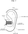
- a state is illustrated in which an acoustic transducer 100 to which the technology disclosed herein has been applied is fitted into an auricle (left ear) of a person.
- a vertical sectional view of a head (ear canal) of the person wearing the acoustic transducer 100 is illustrated.
- An ear canal 200 is a hole which starts from an ear canal entrance 201 and ends at the inside of an eardrum 202.
- the length of the ear canal 200 is generally about 25 to 30 mm.
- an auricle 203 has a complicated uneven shape caused by a shape of an auricle cartilage and is positioned on the outside of the ear canal 200.
- a rough description of the structure of the auricle 203 includes a helix, an anthelix, an ear concha, and a tragus in order starting from the outer side of the auricle 203.
- the ear concha is a most concave part positioned at the center of the ear, and the ear canal entrance 201 is positioned near the tragus of the cavum conchae which is positioned in a lower half of the ear concha.
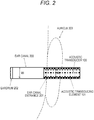
- the ear canal 200 generally meanders in an S-shape. However, the ear canal 200 is illustrated in a cylindrical shape in Fig. 2 for simplification.
- the acoustic transducer 100 to which the technology disclosed herein has been applied includes a cylindrical acoustic transducing element 101 formed of a film-shaped material having an expanding and contracting action.
- the acoustic transducing element 101 can function as a reproduction device for generating a sound by the expanding and contracting action according to an electric signal and a sound collection device for converting vibration caused by the received sound wave into the electric signal (to be described below).
- the cylindrical acoustic transducing element 101 functions as a nonreflective type acoustic tube and the reproduction device. When generating the sound wave, the acoustic transducing element 101 can prevent re-reflection of the sound wave reflected by an eardrum.
- the acoustic transducing element 101 as a basic component is formed in a compact and lightweight shape, the acoustic transducer 100 can generate the sound wave for directly reaching the eardrum or can collect the sound at a place near the eardrum without the feeling of foreign materials in a case where the person wears it on the ear.
- the acoustic transducing element 101 is formed by processing a sheet-shaped flexible device into a cylindrical shape.
- Fig. 3 a diagram of a principle of a conversion action of the acoustic transducing element is illustrated.
- the acoustic transducing element includes a sheet-shaped flexible plane device 301 and metal layers 302 and 303 disposed on both surfaces of the device 301. Then, when an electric signal is applied between the metal layers 302 and 303 on both surfaces, the area of the device 301 is enlarged or reduced as indicated by a reference number 310 according to the polarity of the electric signal.
- the device 301 basically expands and contracts in a horizontal direction perpendicular to the electric field.
- a structure can be used in which particles having piezoelectricity are dispersed in a flexible organic material (resin) (for example, refer to Patent Documents 3 and 4).
- Fig. 4 is a sectional view of the acoustic transducing element 101 formed by processing a sheet-shaped flexible device 401 illustrated in Fig. 3 into a cylindrical shape and forming metal layers 402 and 403 on the inner surface and the outer surface of the flexible device 401.
- Fig. 5 is a longitudinal sectional view of the acoustic transducing element 101 illustrated in Fig. 4 .
- the electric signal is applied to the device 301 via the metal layers 302 and 303 on both side surfaces to expand and contract the device 301 in an area direction 310 according to the polarity.
- the application of the electric signal expands and contracts the device 401 in a radial direction as indicated by a reference number 410 according to the polarity.
- sound waves 511 and 512 are emitted in two directions toward exits at both ends in the cylinder by expanding and contracting movements 501 and 502 of the cylindrical device 401 in the radial direction.
- the acoustic transducing element 101 configured as the cylindrical device 401 can function not only as a voice reproduction device (actuator) for converting the applied electric signal into the sound wave as illustrated in Fig. 5 but also as a sound collection device (transducer) for converting the input sound wave into the electric signal.
- a state is illustrated in which sound waves 611 and 612 enter the cylindrical device 401 from entrances at both ends (or one end).
- the sound waves 611 and 612 which have entered the device 401 cause expansion and contraction of the cylindrical device 401 in the radial direction as indicated by reference numbers 601 and 602.
- a potential difference between the polarities according to the movement of the expansion and contraction of the cylindrical device 401 in the radial direction is generated between both side surfaces of the device 401, and the device 401 generates the electric signal according to the entered sound wave and functions as a transducer.
- the cylindrical acoustic transducing element 101 is formed to have an inner diameter W almost the same as an inner diameter W i of the ear canal 200. Strictly, the inner diameter W of the acoustic transducing element 101 is smaller than the inner diameter W i of the ear canal 200 by twice the thickness t of the sheet.
- the acoustic transducing element 101 is formed as a long tubular body having the almost uniform inner diameter W in the longitudinal direction, that is, as an acoustic tube.
- the inside of the tube acts as a sound path through which the sound wave generated by the acoustic transducing element 101 is transmitted.
- the inner diameter W of the acoustic transducing element 101 as the acoustic tube is almost the same as the inner diameter W i of the ear canal, one end of the acoustic transducing element 101 can be inserted into the ear canal entrance 201, and the sound wave emitted from the end of the acoustic transducing element 101 can enter the ear canal 200 without changing the acoustic impedance.
- the inner diameter W of the acoustic transducing element 101 be almost the same as an average inner diameter of the ear canal of the person.
- the average value of the inner diameter W i of the ear canals of the adults is about 7.5 mm. Therefore, when the inner diameter W of the acoustic transducing element 101 is set to be from 6 to 9 mm, a difference between sectional areas of the acoustic transducing element 101 and the ear canal entrance 201 can be reduced, and the reflection is not caused. As a result, generation of a standing wave can be prevented, and an excellent acoustic characteristic can be obtained while preventing the reflected sound from reaching the eardrum 202.
- the acoustic transducing element 101 is formed in a shape having almost the same inner diameter in the longitudinal direction and having a certain length.
- the acoustic transducing element 101 is formed in a tube-like shape having the same inner diameter and a certain length. According to this, even when the sound reflected by the eardrum 202 enters the tube from one end, the sound is attenuated before the sound reaches the other end, and the sound is prevented from being reflected by the other end. Also, in the example illustrated in Fig. 2 , both ends of the acoustic transducing element 101 are opened. Therefore, the reflected sound which has reached the other end is not reflected again and does not return to the ear canal 200.
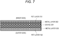
- the basic components of the acoustic transducing element 101 are the device 301 which expands and contracts in response to the applied electric signal and the metal layers 302 and 303 to which the electric signals are applied from both side surfaces.
- the metal layers 302 and 303 are formed of, for example, a copper foil provided and stuck on the surface of the device 301. It is necessary for the copper foil to prevent peeling caused by a contact with external objects (for example, inner circumference of ear canal and finger of person for using acoustic transducer 100).
- Fig. 7 is a diagram of an exemplary configuration of the acoustic transducing element 101 including protective polyethylene terephthalate (PET) layers 701 and 702 respectively disposed on an outer side of the metal layers 302 and 303.
- PET polyethylene terephthalate
- the PET layer 702 may be disposed on the outer side surface of the metal layer 303.
- the acoustic transducing element 101 illustrated in Fig. 4 can be produced by rounding the sheet-shaped flexible device illustrated in Figs. 7 and 8 into a cylindrical shape.
- the cylindrical acoustic transducing element 101 be formed by laminating two or more layers, not a single layer, of the sheet-shaped flexible devices illustrated in Figs. 7 and 8 .
- the single acoustic transducing element 101 be formed by concentrically superposing multiple cylinders, and the radius of one cylinder is made to be slightly larger than that of the inner cylinder (not shown).
- the cylinders are superposed so that the polarities of the layers coincide with each other.
- the single acoustic transducing element 101 may be formed by preparing a single sheet of a flexible device and winding it in a spiral shape. In a case of the acoustic transducing element 101 having a spiral structure, all the layers of the devices are integrated. Therefore, the electric signal may be applied to a single position as illustrated in Fig. 19 . In a case of the acoustic transducing element 101 having a multi-layer structure, when the electric signal is applied, expansion forces and contraction forces generated in each layer are accumulated. Therefore, a larger sound pressure can be obtained.
- a fitting member (earpiece) 901 is disposed at one end side of the acoustic transducing element 101.
- the fitting member 901 is formed of a flexible synthetic resin or a rubber material.
- the fitting member 901 improves the feeling of fitting it into the auricle and prevents sound leakage from the vicinity of the ear canal entrance 201.
- an inner diameter of the fitting member 901 is set to be the size which does not change the characteristic of the acoustic impedance in the cylinder of the acoustic transducing element 101.
- the fitting member 901 can be detached from the acoustic transducing element 101 and can be exchanged.
- the fitting member 901 may be fixed to one end of the acoustic transducing element 101 or may be integrated with the acoustic transducing element 101.
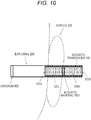
- FIG. 10 another modification of the acoustic transducer 100 illustrated in Fig. 2 is illustrated.
- an acoustic material 1001 for closing the cylinder of the acoustic transducing element 101 is disposed. That is, the acoustic transducer 100 illustrated in Fig. 10 is formed to promptly realize attenuation of the sound by using the acoustic material 1001.
- the acoustic transducer 100 can be miniaturized. Also, since leakage of acoustic energy generated in the acoustic transducing element 101 to the outside is reduced, a bass part of the sound wave which enters the ear canal from the ear canal entrance can be enhanced.
- the acoustic material 1001 prevents the leakage of the sound generated in the acoustic transducing element 101 to the outside by promptly attenuating it. In addition, the acoustic material 1001 prevents the external sound from entering the acoustic transducing element 101, and the sound can be excellently listened. Conversely, in the exemplary configurations illustrated in Figs. 2 and 9 in which the acoustic material is not used and the exit to the outside of the acoustic transducing element 101 is opened, there is an advantage such that external sounds can be concurrently listened when the sound generated in the acoustic transducing element 101 is listened.
- the acoustic material 1001 is disposed almost at the center of the cylinder configuring the acoustic transducing element 101.
- the acoustic transducing element 101 has a cylindrical shape and has an even cross-sectional area in the longitudinal direction. Therefore, the acoustic characteristic does not change. In this case, it can be considered that acoustic impedances of a left part 101L and a right part 101R of the acoustic transducing element 101 divided by the acoustic material 1001 are almost the same.
- the acoustic transducing element 101 When it is assumed that the acoustic transducing element 101 generates almost uniform sound waves rightward and leftward (that is, the sound waves 511 and 512 which travel to the exits in opposite directions have the same sound qualities in Fig. 5 ), the same sounds can be listened from both the right and left ends of the acoustic transducing element 101. Therefore, when either one of the ends 101A and 101B of the acoustic transducing element 101 is inserted into the ear canal entrance, the same sound can be listened.
- Fig. 11 is a diagram of a modification of the acoustic transducer 100 illustrated in Fig. 10 .
- the acoustic material 100 is disposed on the right side of the vicinity of the center of the cylinder for forming the acoustic transducing element 101, and the left part 101L of the acoustic transducing element 101 gets longer, and the right part 10R gets shorter. Also, the acoustic impedances of the left and right parts become uneven. Therefore, use forms may be appropriately used according to the sound to be listened. For example, when the listener listens to music, it is preferable that the side of the end 101A be inserted into the ear canal entrance as illustrated in Fig.
- the listener wants to listen to a voice such as a radio broadcast DJ, it is preferable that the side of the end 101B be inserted into the ear canal entrance to remove the bass part which does not include a voice component by using the right part 101R having a short sound path.
- the acoustic material 1001 is disposed in the acoustic transducing element 101, and the cylinder is closed.
- the acoustic material be arranged near the end on the opposite side of the ear canal entrance to close the acoustic transducing element 101.
- the end where the element 101 is not closed can be inserted into the ear canal entrance.
- the acoustic transducing element 101 can enhance the bass components of the sound wave to the maximum as an acoustic tube.
- a fitting member may be attached to the end on the side of the ear canal entrance of the acoustic transducing element 101.
- the acoustic material 1001 may be movable in the longitudinal direction without fixing it to a certain place in the cylinder of the acoustic transducing element 101.
- the position of the acoustic material 1001 is moved to change the distance from each of the left and right exits. Accordingly, the volume in the ear canal and the cylinder of the acoustic transducing element 101 is changed, and a frequency characteristic of the sound wave for entering from the ear canal entrance can be adjusted.
- FIGs. 12(a) to 12(c) an exemplary configuration of an acoustic transducing element 101 including a moving mechanism of an acoustic material 1001 is illustrated.
- Fig. 12(a) is a top view of the acoustic transducing element 101.
- Fig. 12(b) is a sectional view of the acoustic transducing element 101 in the longitudinal direction cut along a line A-A.
- Fig. 12(c) is a cross-sectional view of the acoustic transducing element 101 cut along a line B-B.
- a linear guide groove 1201 is provided in the cylindrical acoustic transducing element 101 in the longitudinal direction. Also, the disk-shaped acoustic material 1001 is inserted into the cylinder of the acoustic transducing element 101. As it is shown in Figs. 12(b) and 12(c) , a projection 1202 is formed at a single part of a periphery of the acoustic material 1001. As it is shown in Figs. 12(a) to (c) , the projection 1202 is inserted into the guide groove 1201, and a front end part of the projection 1202 is exposed to external environment from the guide groove 1201.
- a wearer of the acoustic transducer 100 can move the acoustic material 1001 by operating the projection 1202 with a fingertip and the like.
- the movement of the projection 1202, that is, the acoustic material 1001 is regulated by the linear guide groove 1201.
- a position where the acoustic transducing element 101 is closed can be freely changed.
- the acoustic transducer 100 illustrated in Fig. 13 includes an external housing 1301, which is attached to the outside of the cylindrical acoustic transducing element 101, to keep the shape.
- the acoustic transducing element 101 is a soft structure in which the metal layer such as the copper foil and the PET layer are formed on both side surfaces of the flexible device.
- the external housing 1301 is a comparatively strong structure which has a cylindrical shape having an inner diameter larger than the outer shape of the acoustic transducing element 101.
- the external housing 1301 holds the acoustic transducing element 101 by inserting it into the external housing 1301. Accordingly, even when the acoustic transducing element 101 is flexible and soft, deformation of the acoustic transducing element 101 caused by a physical pressure from outside can be prevented.
- a purpose for providing the external housing 1301 is to hold the acoustic transducing element 101. Therefore, the external housing 1301 may be sealed and may open the acoustic transducing element 101 to outside as a net.
- the external housing 1301 When the external housing 1301 is sealed, an effect on preventing the sound wave from being emitted outside from the acoustic transducing element 101 is obtained by closing an exit on the opposite side of the ear canal entrance of the acoustic transducing element 101. Also, the external housing 1301 has an effect on preventing the sound wave from entering the acoustic transducing element 101 from outside.
- the external housing 1301 may be formed as a removable cap for closing an opening end of the cylindrical acoustic transducing element 101.
- a modification of the acoustic transducer 100 illustrated in Fig. 13 is illustrated.
- an acoustic material 1401 is inserted into the cylindrical acoustic transducing element 101.
- the external housing 1301 is a structure which has a cylindrical shape having an inner diameter larger than the outer shape of the acoustic transducing element 101.
- the external housing 1301 holds the acoustic transducing element 101 by inserting it into the external housing 1301. Accordingly, even when the acoustic transducing element 101 is flexible and soft, deformation of the acoustic transducing element 101 caused by a physical pressure from outside can be prevented.
- a purpose for providing the external housing 1301 is to hold the acoustic transducing element 101. Therefore, the external housing 1301 may be sealed and may open the acoustic transducing element 101 to outside as a net. When the external housing 1301 is sealed, an effect on preventing the sound wave from being emitted outside from the acoustic transducing element 101 is obtained. Also, the acoustic material 1401 prevents that the sound wave generated by the acoustic transducing element 101 is reflected after the sound wave has reached the eardrum 202 and enters the eardrum 202 by being re-reflected in the acoustic transducing element 101.
- a modification of the acoustic transducer 100 illustrated in Fig. 14 is illustrated.
- an acoustic material 1501 is disposed in a gap between the cylindrical acoustic transducing element 101 and the external housing 1301 where the acoustic transducing element 101 is inserted.
- the external housing 1301 is a structure which has a cylindrical shape having an inner diameter larger than the outer shape of the acoustic transducing element 101.
- the external housing 1301 holds the acoustic transducing element 101 by inserting it into the external housing 1301.
- a purpose for providing the external housing 1301 is to hold the acoustic transducing element 101. Therefore, the external housing 1301 may be sealed and may open the acoustic transducing element 101 to outside as a net. When the external housing 1301 is sealed, an effect on preventing the sound wave from being emitted outside from the acoustic transducing element 101 is obtained.
- the acoustic material 1401 prevents that the sound wave generated by the acoustic transducing element 101 is reflected after the sound wave has reached the eardrum 202 and enters the eardrum 202 by being re-reflected in the acoustic transducing element 101. Also, the acoustic material 1501 has an effect on preventing the sound wave generated by the acoustic transducing element 101 from being emitted outside from the outer periphery.
- a fitting member may be attached to the end on the side of the ear canal entrance of the acoustic transducing element 101.
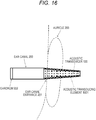
- Fig. 16 yet another modification of the acoustic transducer 100 illustrated in Fig. 2 is illustrated.
- the acoustic transducing element 101 has a uniform cross-sectional area in the longitudinal direction, for example, as a cylindrical shape, and the acoustic material 1001 is squeezed into the acoustic transducing element 101. Then, the acoustic transducing element 101 can prevent the leakage of the sound generated by the acoustic transducing element 101 to the outside.
- Fig. 10 , 11 , and 12(a) to 12(c) the acoustic transducing element 101 has a uniform cross-sectional area in the longitudinal direction, for example, as a cylindrical shape, and the acoustic material 1001 is squeezed into the acoustic transducing element 101. Then, the acoustic transducing element 101 can prevent the leakage of the sound generated by the acoustic transducing element 101 to the outside.
- a hollow acoustic transducing element 1601 has a shape with a cross-sectional area which is gradually decreased as moving in the longitudinal direction, such as a conical shape.
- the sound wave reflected by the eardrum is hardly emitted to the outside even when the sound wave is re-reflected by the acoustic transducing element 1601. Therefore, although the acoustic transducing element 1601 has an opening end, the leakage of the sound generated by the acoustic transducing element 1601 to the outside can be prevented without providing an acoustic material.
- a fitting member may be attached to the end on the side of the ear canal entrance of the acoustic transducing element 101.
- Fig. 17 still yet another modification of the acoustic transducer 100 illustrated in Fig. 2 is illustrated.
- the cylindrical acoustic transducing element 101 can be used as a transducer for converting the sound wave which has entered the cylinder from the end into the electric signal.
- the acoustic transducer 100 is used as a microphone. That is, the electric signal according to the sound wave can be captured by connecting metal layers on an inner surface and an outer surface of the acoustic transducing element 101 to respective input terminals of a microphone amplifier 1701. By fitting the microphones having the configuration illustrated in Fig.
- the microphone can be used to collect the sound as a dummy head microphone or a binaural microphone to be fitted into ears of a person.
- the acoustic transducer 100 illustrated in Fig. 17 does not include an acoustic material in the acoustic transducing element 101. Therefore, the ear canal entrance is opened. Accordingly, the sound can be collected while an external sound is listened by a real ear.
- a modification of the acoustic transducer 100 illustrated in Fig. 17 is illustrated.
- an output to a microphone amplifier 1701 and to a speaker amplifier 1801 is switched by a switcher 1800.
- the microphone amplifier 1701 inputs the electric signals from the inner and outer metal layers of the acoustic transducing element 101 by the respective input terminals, and the speaker amplifier 1801 outputs the electric signals from the respective output terminals to the inner and outer metal layers of the acoustic transducing element 101. That is, in the example illustrated in Fig. 18 , the acoustic transducer 100 can function as both the voice reproduction device and the sound collection device.
- a fitting member may be attached to the end on the side of the ear canal entrance of the acoustic transducing element 101.
- the acoustic transducer 100 has a simple, compact, and lightweight configuration and is operated as a nonreflective type headphone. Also, the acoustic transducer 100 has an excellent sound image localization, and a listener can listen to an external sound while listening to a sound. In addition, the acoustic transducer 100 can be also operated as a binaural microphone.
- the embodiment has been mainly described in which the cylindrical or conical acoustic transducing element is formed by using the sheet-shaped flexible device having an area enlarged or reduced in response to the characteristic of the electric signal to be applied.
- the scope of the technology disclosed herein is not limited to this.
- an acoustic transducer having a similar acoustic characteristic can be realized by using an acoustic transducing element formed in various hollow shapes other than a cylinder and a circular cone.
Landscapes
- Engineering & Computer Science (AREA)
- Physics & Mathematics (AREA)
- Acoustics & Sound (AREA)
- Signal Processing (AREA)
- Manufacturing & Machinery (AREA)
- Headphones And Earphones (AREA)
Applications Claiming Priority (2)
| Application Number | Priority Date | Filing Date | Title |
|---|---|---|---|
| JP2014223345 | 2014-10-31 | ||
| PCT/JP2015/070303 WO2016067681A1 (ja) | 2014-10-31 | 2015-07-15 | 音響変換装置 |
Publications (3)
| Publication Number | Publication Date |
|---|---|
| EP3214849A1 true EP3214849A1 (de) | 2017-09-06 |
| EP3214849A4 EP3214849A4 (de) | 2018-04-18 |
| EP3214849B1 EP3214849B1 (de) | 2020-04-08 |
Family
ID=55857032
Family Applications (1)
| Application Number | Title | Priority Date | Filing Date |
|---|---|---|---|
| EP15854428.8A Active EP3214849B1 (de) | 2014-10-31 | 2015-07-15 | Vorrichtung mit akustischem wandler |
Country Status (5)
| Country | Link |
|---|---|
| US (1) | US10511902B2 (de) |
| EP (1) | EP3214849B1 (de) |
| JP (1) | JPWO2016067681A1 (de) |
| CN (1) | CN107155406B (de) |
| WO (1) | WO2016067681A1 (de) |
Families Citing this family (4)
| Publication number | Priority date | Publication date | Assignee | Title |
|---|---|---|---|---|
| JP7073646B2 (ja) * | 2017-07-26 | 2022-05-24 | ヤマハ株式会社 | トランスデューサ |
| JP6981178B2 (ja) * | 2017-11-01 | 2021-12-15 | ヤマハ株式会社 | トランスデューサ |
| JP7338147B2 (ja) * | 2018-11-29 | 2023-09-05 | ヤマハ株式会社 | 電気音響変換器 |
| WO2023095757A1 (ja) * | 2021-11-26 | 2023-06-01 | クレプシードラ株式会社 | 音響装置 |
Family Cites Families (20)
| Publication number | Priority date | Publication date | Assignee | Title |
|---|---|---|---|---|
| JPS5920799U (ja) * | 1982-07-27 | 1984-02-08 | 澤藤 正 | 圧電フイルム積層型スピ−カ |
| CA1336295C (en) * | 1988-09-21 | 1995-07-11 | Masayoshi Miura | Sound reproducing apparatus |
| JP2829982B2 (ja) | 1988-09-21 | 1998-12-02 | ソニー株式会社 | 音響再生装置 |
| JP2778053B2 (ja) * | 1988-10-26 | 1998-07-23 | ソニー株式会社 | 音響再生装置 |
| JP2764953B2 (ja) * | 1988-10-28 | 1998-06-11 | ソニー株式会社 | ヘッドホン装置 |
| CN2055311U (zh) * | 1989-03-03 | 1990-03-28 | 姚志强 | 迟滞回弹泡沫材料耳塞装置 |
| WO1991011078A1 (fr) * | 1990-01-19 | 1991-07-25 | Sony Corporation | Casque a deux ecouteurs |
| JPH08275281A (ja) * | 1995-03-31 | 1996-10-18 | Sony Corp | ノイズキャンセル型ヘッドホン |
| JP2001326985A (ja) * | 2000-05-12 | 2001-11-22 | Ccd:Kk | 振動伝達装置 |
| JP4069294B2 (ja) * | 2002-12-26 | 2008-04-02 | Tdk株式会社 | イヤフォン、音声伝達装置 |
| JP4709017B2 (ja) | 2006-01-12 | 2011-06-22 | ソニー株式会社 | イヤホン装置 |
| TWI323617B (en) * | 2006-02-20 | 2010-04-11 | Cotron Corp | Multiple channel earphone |
| JP2009027675A (ja) * | 2007-07-24 | 2009-02-05 | Swcc Showa Device Technology Co Ltd | イヤホンアタッチメント |
| JP5157324B2 (ja) | 2007-08-31 | 2013-03-06 | 株式会社村田製作所 | 圧電構造体とそれを備えたスピーカー |
| DE102008009284B4 (de) * | 2008-02-15 | 2009-10-22 | Siemens Audiologische Technik Gmbh | Wasserresistentes Hörgerät |
| US8798298B1 (en) * | 2008-12-31 | 2014-08-05 | Starkey Laboratories, Inc. | Constrained layer damping for hearing assistance devices |
| JP5617069B2 (ja) * | 2009-10-09 | 2014-11-05 | 国立大学法人九州工業大学 | スピーカ |
| CN102006543B (zh) * | 2010-12-03 | 2015-04-29 | 江苏贝泰福医疗科技有限公司 | 一种新型耳内助听器 |
| WO2012103935A1 (en) * | 2011-02-01 | 2012-08-09 | Phonak Ag | Hearing device with a receiver module and method for manufacturing a receiver module |
| CN103843365B (zh) | 2011-09-30 | 2016-08-17 | 富士胶片株式会社 | 电声转换膜、柔性显示器、声带麦克风以及乐器传感器 |
-
2015
- 2015-07-15 CN CN201580057493.5A patent/CN107155406B/zh not_active Expired - Fee Related
- 2015-07-15 US US15/520,453 patent/US10511902B2/en not_active Expired - Fee Related
- 2015-07-15 EP EP15854428.8A patent/EP3214849B1/de active Active
- 2015-07-15 WO PCT/JP2015/070303 patent/WO2016067681A1/ja not_active Ceased
- 2015-07-15 JP JP2016556389A patent/JPWO2016067681A1/ja active Pending
Also Published As
| Publication number | Publication date |
|---|---|
| EP3214849B1 (de) | 2020-04-08 |
| WO2016067681A1 (ja) | 2016-05-06 |
| EP3214849A4 (de) | 2018-04-18 |
| JPWO2016067681A1 (ja) | 2017-08-10 |
| US10511902B2 (en) | 2019-12-17 |
| CN107155406A (zh) | 2017-09-12 |
| US20170318373A1 (en) | 2017-11-02 |
| CN107155406B (zh) | 2019-07-09 |
Similar Documents
| Publication | Publication Date | Title |
|---|---|---|
| JP6652164B2 (ja) | 音響出力装置 | |
| US11057695B2 (en) | In-ear headphone device with active noise control | |
| US9813794B2 (en) | Noise reduction with in-ear headphone | |
| JP5363825B2 (ja) | ノイズキャンセルヘッドホン | |
| CN102123334B (zh) | 带有周向麦克风狭槽的通信头戴式耳麦 | |
| JP2010157814A (ja) | イヤホン構造体、挿入部材及びイヤホン | |
| JP2012244350A (ja) | カナル型イヤホン | |
| US10511902B2 (en) | Acoustic transducer | |
| CN211744683U (zh) | 包括dsf通道的入耳式耳机 | |
| JP7264052B2 (ja) | 音響出力装置 | |
| WO2007099893A1 (ja) | 音声入力イヤーマイク | |
| EP3200476B1 (de) | Kopfhörer | |
| JP5872722B1 (ja) | 連通管付きイヤホン | |
| JP2019087790A (ja) | トランスデューサ | |
| JP6268909B2 (ja) | 音響システムおよび超音波フィルタ | |
| JP6421360B2 (ja) | インナーイヤホン | |
| WO2016181431A1 (ja) | 連通部付き密閉イヤホン | |
| CN116419109B (zh) | 耳机和终端设备 | |
| JP7347927B2 (ja) | 電気音響変換器及び音響機器 | |
| CN205265867U (zh) | 一种新型喇叭网罩 | |
| JP3197746U (ja) | カナル型イヤホン | |
| CN204681547U (zh) | 入耳式耳机的听筒结构 | |
| JP2016201786A (ja) | 連通管付きイヤホン | |
| JP2004126258A (ja) | 装着型通信装置 | |
| JP2013160824A (ja) | 凹型集音補聴具 |
Legal Events
| Date | Code | Title | Description |
|---|---|---|---|
| STAA | Information on the status of an ep patent application or granted ep patent |
Free format text: STATUS: THE INTERNATIONAL PUBLICATION HAS BEEN MADE |
|
| PUAI | Public reference made under article 153(3) epc to a published international application that has entered the european phase |
Free format text: ORIGINAL CODE: 0009012 |
|
| STAA | Information on the status of an ep patent application or granted ep patent |
Free format text: STATUS: REQUEST FOR EXAMINATION WAS MADE |
|
| 17P | Request for examination filed |
Effective date: 20170419 |
|
| AK | Designated contracting states |
Kind code of ref document: A1 Designated state(s): AL AT BE BG CH CY CZ DE DK EE ES FI FR GB GR HR HU IE IS IT LI LT LU LV MC MK MT NL NO PL PT RO RS SE SI SK SM TR |
|
| AX | Request for extension of the european patent |
Extension state: BA ME |
|
| DAV | Request for validation of the european patent (deleted) | ||
| DAX | Request for extension of the european patent (deleted) | ||
| A4 | Supplementary search report drawn up and despatched |
Effective date: 20180315 |
|
| RIC1 | Information provided on ipc code assigned before grant |
Ipc: H04R 1/10 20060101AFI20180309BHEP Ipc: H04R 17/00 20060101ALN20180309BHEP Ipc: H04R 17/02 20060101ALN20180309BHEP |
|
| STAA | Information on the status of an ep patent application or granted ep patent |
Free format text: STATUS: EXAMINATION IS IN PROGRESS |
|
| 17Q | First examination report despatched |
Effective date: 20190524 |
|
| GRAP | Despatch of communication of intention to grant a patent |
Free format text: ORIGINAL CODE: EPIDOSNIGR1 |
|
| STAA | Information on the status of an ep patent application or granted ep patent |
Free format text: STATUS: GRANT OF PATENT IS INTENDED |
|
| RIC1 | Information provided on ipc code assigned before grant |
Ipc: H04R 17/00 20060101ALN20191001BHEP Ipc: H04R 1/10 20060101AFI20191001BHEP Ipc: H04R 17/02 20060101ALN20191001BHEP |
|
| RIC1 | Information provided on ipc code assigned before grant |
Ipc: H04R 1/10 20060101AFI20191011BHEP Ipc: H04R 17/00 20060101ALN20191011BHEP Ipc: H04R 17/02 20060101ALN20191011BHEP |
|
| INTG | Intention to grant announced |
Effective date: 20191104 |
|
| GRAS | Grant fee paid |
Free format text: ORIGINAL CODE: EPIDOSNIGR3 |
|
| GRAA | (expected) grant |
Free format text: ORIGINAL CODE: 0009210 |
|
| STAA | Information on the status of an ep patent application or granted ep patent |
Free format text: STATUS: THE PATENT HAS BEEN GRANTED |
|
| AK | Designated contracting states |
Kind code of ref document: B1 Designated state(s): AL AT BE BG CH CY CZ DE DK EE ES FI FR GB GR HR HU IE IS IT LI LT LU LV MC MK MT NL NO PL PT RO RS SE SI SK SM TR |
|
| REG | Reference to a national code |
Ref country code: CH Ref legal event code: EP Ref country code: AT Ref legal event code: REF Ref document number: 1255984 Country of ref document: AT Kind code of ref document: T Effective date: 20200415 |
|
| REG | Reference to a national code |
Ref country code: DE Ref legal event code: R096 Ref document number: 602015050498 Country of ref document: DE |
|
| REG | Reference to a national code |
Ref country code: IE Ref legal event code: FG4D |
|
| REG | Reference to a national code |
Ref country code: NL Ref legal event code: MP Effective date: 20200408 |
|
| REG | Reference to a national code |
Ref country code: LT Ref legal event code: MG4D |
|
| PG25 | Lapsed in a contracting state [announced via postgrant information from national office to epo] |
Ref country code: LT Free format text: LAPSE BECAUSE OF FAILURE TO SUBMIT A TRANSLATION OF THE DESCRIPTION OR TO PAY THE FEE WITHIN THE PRESCRIBED TIME-LIMIT Effective date: 20200408 Ref country code: NL Free format text: LAPSE BECAUSE OF FAILURE TO SUBMIT A TRANSLATION OF THE DESCRIPTION OR TO PAY THE FEE WITHIN THE PRESCRIBED TIME-LIMIT Effective date: 20200408 Ref country code: PT Free format text: LAPSE BECAUSE OF FAILURE TO SUBMIT A TRANSLATION OF THE DESCRIPTION OR TO PAY THE FEE WITHIN THE PRESCRIBED TIME-LIMIT Effective date: 20200817 Ref country code: NO Free format text: LAPSE BECAUSE OF FAILURE TO SUBMIT A TRANSLATION OF THE DESCRIPTION OR TO PAY THE FEE WITHIN THE PRESCRIBED TIME-LIMIT Effective date: 20200708 Ref country code: GR Free format text: LAPSE BECAUSE OF FAILURE TO SUBMIT A TRANSLATION OF THE DESCRIPTION OR TO PAY THE FEE WITHIN THE PRESCRIBED TIME-LIMIT Effective date: 20200709 Ref country code: FI Free format text: LAPSE BECAUSE OF FAILURE TO SUBMIT A TRANSLATION OF THE DESCRIPTION OR TO PAY THE FEE WITHIN THE PRESCRIBED TIME-LIMIT Effective date: 20200408 Ref country code: IS Free format text: LAPSE BECAUSE OF FAILURE TO SUBMIT A TRANSLATION OF THE DESCRIPTION OR TO PAY THE FEE WITHIN THE PRESCRIBED TIME-LIMIT Effective date: 20200808 Ref country code: SE Free format text: LAPSE BECAUSE OF FAILURE TO SUBMIT A TRANSLATION OF THE DESCRIPTION OR TO PAY THE FEE WITHIN THE PRESCRIBED TIME-LIMIT Effective date: 20200408 |
|
| PGFP | Annual fee paid to national office [announced via postgrant information from national office to epo] |
Ref country code: GB Payment date: 20200727 Year of fee payment: 6 Ref country code: DE Payment date: 20200721 Year of fee payment: 6 Ref country code: FR Payment date: 20200723 Year of fee payment: 6 |
|
| REG | Reference to a national code |
Ref country code: AT Ref legal event code: MK05 Ref document number: 1255984 Country of ref document: AT Kind code of ref document: T Effective date: 20200408 |
|
| PG25 | Lapsed in a contracting state [announced via postgrant information from national office to epo] |
Ref country code: HR Free format text: LAPSE BECAUSE OF FAILURE TO SUBMIT A TRANSLATION OF THE DESCRIPTION OR TO PAY THE FEE WITHIN THE PRESCRIBED TIME-LIMIT Effective date: 20200408 Ref country code: RS Free format text: LAPSE BECAUSE OF FAILURE TO SUBMIT A TRANSLATION OF THE DESCRIPTION OR TO PAY THE FEE WITHIN THE PRESCRIBED TIME-LIMIT Effective date: 20200408 Ref country code: BG Free format text: LAPSE BECAUSE OF FAILURE TO SUBMIT A TRANSLATION OF THE DESCRIPTION OR TO PAY THE FEE WITHIN THE PRESCRIBED TIME-LIMIT Effective date: 20200708 Ref country code: LV Free format text: LAPSE BECAUSE OF FAILURE TO SUBMIT A TRANSLATION OF THE DESCRIPTION OR TO PAY THE FEE WITHIN THE PRESCRIBED TIME-LIMIT Effective date: 20200408 |
|
| PG25 | Lapsed in a contracting state [announced via postgrant information from national office to epo] |
Ref country code: AL Free format text: LAPSE BECAUSE OF FAILURE TO SUBMIT A TRANSLATION OF THE DESCRIPTION OR TO PAY THE FEE WITHIN THE PRESCRIBED TIME-LIMIT Effective date: 20200408 |
|
| REG | Reference to a national code |
Ref country code: DE Ref legal event code: R097 Ref document number: 602015050498 Country of ref document: DE |
|
| PG25 | Lapsed in a contracting state [announced via postgrant information from national office to epo] |
Ref country code: CZ Free format text: LAPSE BECAUSE OF FAILURE TO SUBMIT A TRANSLATION OF THE DESCRIPTION OR TO PAY THE FEE WITHIN THE PRESCRIBED TIME-LIMIT Effective date: 20200408 Ref country code: IT Free format text: LAPSE BECAUSE OF FAILURE TO SUBMIT A TRANSLATION OF THE DESCRIPTION OR TO PAY THE FEE WITHIN THE PRESCRIBED TIME-LIMIT Effective date: 20200408 Ref country code: ES Free format text: LAPSE BECAUSE OF FAILURE TO SUBMIT A TRANSLATION OF THE DESCRIPTION OR TO PAY THE FEE WITHIN THE PRESCRIBED TIME-LIMIT Effective date: 20200408 Ref country code: RO Free format text: LAPSE BECAUSE OF FAILURE TO SUBMIT A TRANSLATION OF THE DESCRIPTION OR TO PAY THE FEE WITHIN THE PRESCRIBED TIME-LIMIT Effective date: 20200408 Ref country code: DK Free format text: LAPSE BECAUSE OF FAILURE TO SUBMIT A TRANSLATION OF THE DESCRIPTION OR TO PAY THE FEE WITHIN THE PRESCRIBED TIME-LIMIT Effective date: 20200408 Ref country code: EE Free format text: LAPSE BECAUSE OF FAILURE TO SUBMIT A TRANSLATION OF THE DESCRIPTION OR TO PAY THE FEE WITHIN THE PRESCRIBED TIME-LIMIT Effective date: 20200408 Ref country code: AT Free format text: LAPSE BECAUSE OF FAILURE TO SUBMIT A TRANSLATION OF THE DESCRIPTION OR TO PAY THE FEE WITHIN THE PRESCRIBED TIME-LIMIT Effective date: 20200408 Ref country code: SM Free format text: LAPSE BECAUSE OF FAILURE TO SUBMIT A TRANSLATION OF THE DESCRIPTION OR TO PAY THE FEE WITHIN THE PRESCRIBED TIME-LIMIT Effective date: 20200408 |
|
| PLBE | No opposition filed within time limit |
Free format text: ORIGINAL CODE: 0009261 |
|
| STAA | Information on the status of an ep patent application or granted ep patent |
Free format text: STATUS: NO OPPOSITION FILED WITHIN TIME LIMIT |
|
| PG25 | Lapsed in a contracting state [announced via postgrant information from national office to epo] |
Ref country code: SK Free format text: LAPSE BECAUSE OF FAILURE TO SUBMIT A TRANSLATION OF THE DESCRIPTION OR TO PAY THE FEE WITHIN THE PRESCRIBED TIME-LIMIT Effective date: 20200408 Ref country code: MC Free format text: LAPSE BECAUSE OF FAILURE TO SUBMIT A TRANSLATION OF THE DESCRIPTION OR TO PAY THE FEE WITHIN THE PRESCRIBED TIME-LIMIT Effective date: 20200408 Ref country code: PL Free format text: LAPSE BECAUSE OF FAILURE TO SUBMIT A TRANSLATION OF THE DESCRIPTION OR TO PAY THE FEE WITHIN THE PRESCRIBED TIME-LIMIT Effective date: 20200408 |
|
| REG | Reference to a national code |
Ref country code: CH Ref legal event code: PL |
|
| 26N | No opposition filed |
Effective date: 20210112 |
|
| REG | Reference to a national code |
Ref country code: BE Ref legal event code: MM Effective date: 20200731 |
|
| PG25 | Lapsed in a contracting state [announced via postgrant information from national office to epo] |
Ref country code: CH Free format text: LAPSE BECAUSE OF NON-PAYMENT OF DUE FEES Effective date: 20200731 Ref country code: LI Free format text: LAPSE BECAUSE OF NON-PAYMENT OF DUE FEES Effective date: 20200731 Ref country code: LU Free format text: LAPSE BECAUSE OF NON-PAYMENT OF DUE FEES Effective date: 20200715 |
|
| PG25 | Lapsed in a contracting state [announced via postgrant information from national office to epo] |
Ref country code: BE Free format text: LAPSE BECAUSE OF NON-PAYMENT OF DUE FEES Effective date: 20200731 Ref country code: SI Free format text: LAPSE BECAUSE OF FAILURE TO SUBMIT A TRANSLATION OF THE DESCRIPTION OR TO PAY THE FEE WITHIN THE PRESCRIBED TIME-LIMIT Effective date: 20200408 |
|
| PG25 | Lapsed in a contracting state [announced via postgrant information from national office to epo] |
Ref country code: IE Free format text: LAPSE BECAUSE OF NON-PAYMENT OF DUE FEES Effective date: 20200715 |
|
| REG | Reference to a national code |
Ref country code: DE Ref legal event code: R119 Ref document number: 602015050498 Country of ref document: DE |
|
| GBPC | Gb: european patent ceased through non-payment of renewal fee |
Effective date: 20210715 |
|
| PG25 | Lapsed in a contracting state [announced via postgrant information from national office to epo] |
Ref country code: GB Free format text: LAPSE BECAUSE OF NON-PAYMENT OF DUE FEES Effective date: 20210715 Ref country code: DE Free format text: LAPSE BECAUSE OF NON-PAYMENT OF DUE FEES Effective date: 20220201 |
|
| PG25 | Lapsed in a contracting state [announced via postgrant information from national office to epo] |
Ref country code: TR Free format text: LAPSE BECAUSE OF FAILURE TO SUBMIT A TRANSLATION OF THE DESCRIPTION OR TO PAY THE FEE WITHIN THE PRESCRIBED TIME-LIMIT Effective date: 20200408 Ref country code: MT Free format text: LAPSE BECAUSE OF FAILURE TO SUBMIT A TRANSLATION OF THE DESCRIPTION OR TO PAY THE FEE WITHIN THE PRESCRIBED TIME-LIMIT Effective date: 20200408 Ref country code: FR Free format text: LAPSE BECAUSE OF NON-PAYMENT OF DUE FEES Effective date: 20210731 Ref country code: CY Free format text: LAPSE BECAUSE OF FAILURE TO SUBMIT A TRANSLATION OF THE DESCRIPTION OR TO PAY THE FEE WITHIN THE PRESCRIBED TIME-LIMIT Effective date: 20200408 |
|
| PG25 | Lapsed in a contracting state [announced via postgrant information from national office to epo] |
Ref country code: MK Free format text: LAPSE BECAUSE OF FAILURE TO SUBMIT A TRANSLATION OF THE DESCRIPTION OR TO PAY THE FEE WITHIN THE PRESCRIBED TIME-LIMIT Effective date: 20200408 |