EP3220089A1 - System und verfahren zum reinigen eines wärmetauschers - Google Patents
System und verfahren zum reinigen eines wärmetauschers Download PDFInfo
- Publication number
- EP3220089A1 EP3220089A1 EP16305302.8A EP16305302A EP3220089A1 EP 3220089 A1 EP3220089 A1 EP 3220089A1 EP 16305302 A EP16305302 A EP 16305302A EP 3220089 A1 EP3220089 A1 EP 3220089A1
- Authority
- EP
- European Patent Office
- Prior art keywords
- supply
- cleaning
- duct
- heat exchanger
- discharge
- Prior art date
- Legal status (The legal status is an assumption and is not a legal conclusion. Google has not performed a legal analysis and makes no representation as to the accuracy of the status listed.)
- Granted
Links
Images





Classifications
-
- F—MECHANICAL ENGINEERING; LIGHTING; HEATING; WEAPONS; BLASTING
- F28—HEAT EXCHANGE IN GENERAL
- F28D—HEAT-EXCHANGE APPARATUS, NOT PROVIDED FOR IN ANOTHER SUBCLASS, IN WHICH THE HEAT-EXCHANGE MEDIA DO NOT COME INTO DIRECT CONTACT
- F28D11/00—Heat-exchange apparatus employing moving conduits
- F28D11/02—Heat-exchange apparatus employing moving conduits the movement being rotary, e.g. performed by a drum or roller
-
- F—MECHANICAL ENGINEERING; LIGHTING; HEATING; WEAPONS; BLASTING
- F28—HEAT EXCHANGE IN GENERAL
- F28F—DETAILS OF HEAT-EXCHANGE AND HEAT-TRANSFER APPARATUS, OF GENERAL APPLICATION
- F28F27/00—Control arrangements or safety devices specially adapted for heat-exchange or heat-transfer apparatus
- F28F27/02—Control arrangements or safety devices specially adapted for heat-exchange or heat-transfer apparatus for controlling the distribution of heat-exchange media between different channels
-
- F—MECHANICAL ENGINEERING; LIGHTING; HEATING; WEAPONS; BLASTING
- F28—HEAT EXCHANGE IN GENERAL
- F28F—DETAILS OF HEAT-EXCHANGE AND HEAT-TRANSFER APPARATUS, OF GENERAL APPLICATION
- F28F5/00—Elements specially adapted for movement
- F28F5/02—Rotary drums or rollers
-
- F—MECHANICAL ENGINEERING; LIGHTING; HEATING; WEAPONS; BLASTING
- F28—HEAT EXCHANGE IN GENERAL
- F28G—CLEANING OF INTERNAL OR EXTERNAL SURFACES OF HEAT-EXCHANGE OR HEAT-TRANSFER CONDUITS, e.g. WATER TUBES OR BOILERS
- F28G15/00—Details
-
- F—MECHANICAL ENGINEERING; LIGHTING; HEATING; WEAPONS; BLASTING
- F28—HEAT EXCHANGE IN GENERAL
- F28G—CLEANING OF INTERNAL OR EXTERNAL SURFACES OF HEAT-EXCHANGE OR HEAT-TRANSFER CONDUITS, e.g. WATER TUBES OR BOILERS
- F28G15/00—Details
- F28G15/003—Control arrangements
-
- F—MECHANICAL ENGINEERING; LIGHTING; HEATING; WEAPONS; BLASTING
- F28—HEAT EXCHANGE IN GENERAL
- F28G—CLEANING OF INTERNAL OR EXTERNAL SURFACES OF HEAT-EXCHANGE OR HEAT-TRANSFER CONDUITS, e.g. WATER TUBES OR BOILERS
- F28G9/00—Cleaning by flushing or washing, e.g. with chemical solvents
Definitions
- the invention relates to a cleaning system for a cylindrical heat exchanger of the rotary industrial roller type.
- the industrial roller ensuring the path of such a film is in this case a heat exchanger comprising two concentric inner and outer cylindrical walls, channels housed in the space defined between the inner and outer walls and in which can circulate a heat transfer fluid ensuring a heat exchange with the outer cylindrical wall, the exchanger further comprising at least one conduit for supplying heat transfer fluid channels via supply tubes, each connecting the supply duct to the inlet of a channel, and at least one duct for evacuating the heat transfer fluid channels via evacuation tubes, each connecting the outlet of a channel to the evacuation duct.
- the circulation of the heat transfer fluid in the channels ensures the stability and the uniformity of the temperature of the entire external surface of the external wall of the heat exchanger, ensuring the uniform cooling of the hot extruded film conveyed by the heat
- the heat transfer fluid is treated to contain as few impurities as possible, it is common for material deposits to reduce the cross section of the channels, including scale deposits, rust, grease or oil, of bacteria. This causes a decrease in the flow of heat transfer fluid circulating in this channel and therefore a decrease in heat exchange between the heat transfer fluid and the film to be cooled. The temperature of the fluid flowing in this partially clogged channel therefore tends to increase, thus affecting the uniformity of the temperature of the outer surface of the outer wall of the heat exchanger and the proper cooling of the hot extruded film.
- the present invention aims to overcome the above disadvantages of the prior art.
- the invention relates to a cleaning system of a rotary cylindrical heat exchanger as described above, the cleaning system comprising a removable closure means for insertion into the supply duct to seal the inlets of the supply tubes connected to the supply duct, and cleaning ducts each connected to a supply tube downstream of its inlet and arranged to be connected to a source of a cleaning fluid for injecting the cleaning fluid; cleaning that can circulate in the corresponding channel and the evacuation tube to the cleaning fluid evacuation duct.
- the cleaning system comprises a device for monitoring the temperature of the coolant circulating in the channels and comprising temperature sensors, each of which makes it possible to periodically measure the temperature of the coolant circulating in the corresponding evacuation tube, and an external processing unit of the temperature data from the temperature sensors and arranged to generate information of the need for cleaning at least one channel when the temperature of the coolant in the corresponding discharge tube exceeds a value temperature threshold stored in the temperature data processing unit.
- each temperature sensor comprises a probe in contact with the corresponding discharge tube and an acquisition unit of the temperature data measured by the probe housed in a compartment of the heat exchanger, the unit of acquisition being arranged to transmit periodically to the processing unit the acquired temperature data.
- the communication between the data acquisition means and the data processing means is of the wireless type.
- the removable closure means comprises a rod whose end portion comprises seals for sealing the inlet of the supply tubes.
- the supply and discharge ducts are cylindrical.
- the heat exchanger comprises a pair of respectively supply and discharge conduits disposed at one end of the heat exchanger.
- the two supply and discharge ducts respectively arranged at the same end of the heat exchanger are mounted concentrically, the diameter of the discharge duct being greater than the diameter of the supply duct so that the evacuation of heat transfer fluid or cleaning fluid is carried out along the annular space formed between the two walls of the two ducts respectively supply and discharge.
- each supply tube is connected at its inlet radially to the exhaust duct, and each evacuation tube is connected at its output radially to the exhaust duct.
- the heat exchanger comprises a feed duct disposed at one end of the heat exchanger and a discharge duct disposed at the opposite end of this exchanger.
- the channels of the heat exchanger are constituted by metal strips spirally wound around the inner cylindrical wall of the heat exchanger defining between them the coolant circulation channels and which are welded to the surface external of this inner cylindrical wall.
- the heat exchanger comprises six channels.
- the heat exchanger comprises eight channels.
- the cleaning fluid has detergent and / or descaling and / or rustproofing properties.
- such a heat exchanger 1 is used in particular to uniformly cool films of low thermal conductivity material, including hot-extruded plastic films.
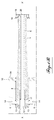
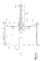
- the heat exchanger 1 comprises two inner cylindrical walls 2 and outer 3 concentric with their two opposite ends of two transverse walls 32.
- the inner cylindrical wall 2 rests at each of its opposite ends on convex internal shoulders formed in the corresponding transverse wall 32 of the heat exchanger 1 and is fixed to these shoulders by welding.
- the two inner cylindrical walls 2 and outer 3 define between them an annular space.
- the two transverse walls 32 protrude radially from their outer peripheral edge 32b of the outer peripheral surface of the inner cylindrical wall 2.
- the outer cylindrical wall 3 rests at each of its two opposite ends on the outer peripheral edges 32b of the transverse walls 32 and is attached thereto by welding.
- the heat exchanger 1 further comprises circulation channels 4 of a heat transfer fluid, housed in the annular space between the inner cylindrical walls 2 and outer wall 3 so that the heat transfer fluid flowing in these channels 4 ensures an exchange thermal device with the entirety of the outer cylindrical wall 3.
- these channels 4 are constituted by rigid metal strips 4b spirally wound around the inner cylindrical wall 2 defining between them the circulation channels 4 of the coolant.
- the metal strips 4b are on the one hand supported by their edges on the same side on the outer surface of the inner cylindrical wall 2 of the heat exchanger 1 and welded to this surface, and on the other hand supported by their opposite edges on the inner surface of the outer cylindrical wall 3. Therefore, the metal strips 4b are sealingly fixed between the two inner and outer walls 2 to define the individual channels 4.
- the flow of coolant in the channels 4 is provided by a heat transfer fluid supply duct 5 via supply tubes 6, each connecting the supply duct 5 to the inlet 7 of a channel 4, and by a heat transfer fluid discharge duct 8 via discharge tubes 9, each connecting the outlet 10 of a channel 4 to the discharge duct 8.
- the inlet 7 and the outlet 10 of a channel 4 are formed by radial holes made in the inner cylindrical wall 2 in the vicinity respectively of the ends of the inner cylindrical wall 2, that is to say that these radial holes 7, 10 respectively open at both ends of the spiral of the corresponding channel 4.
- the supply and exhaust ducts 8 consist of rigid cylindrical and concentric tubes, and the exhaust duct 8 is plugged at an end opposite to that for the discharge of heat transfer fluid through a closure wall 11 welded to the corresponding end of the exhaust duct 8.
- These two ducts 5, 8 are arranged at one end of the heat exchanger 1 coaxially with the axis of rotation XX 'of the exchanger 1. More specifically, the exhaust duct 8 whose diameter is greater than the diameter of the supply duct 5 through the corresponding transverse wall 32 and is secured thereto by welding.
- This exhaust duct 8 also serves as a half axis of rotation of the heat exchanger 1.
- the supply duct 5 extends in the evacuation duct 8 over a large part of the length of the latter and at its end opening facing the transverse closing wall 11 of the evacuation duct 8.
- This end of the supply duct 5 comprises a metal ring 17 integral with this end and which comprises an O-ring seal (not shown) resting on the internal surface of the evacuation duct 8.
- this supply duct 5 is integral with a circular cover 18 removably attached to a flange 19 secured to the corresponding end of the exhaust duct 8, the cover 18 allowing the passage of a means of removable closure of the supply tubes 6 as will be seen later.
- Each supply tube 6 is connected at its inlet 14 radially to the exhaust duct 8 via radial holes 13 positioned downstream of the O-ring with respect to the direction of flow of the coolant in the supply duct 5, which radial holes 13 open into the chamber 12 defined between the O-ring and the closure wall 11 of the exhaust duct 8.
- the coolant coming from the supply duct 5 is distributed in the supply tubes 6 in the direction of the entrance 7 of the channels 4.
- Each discharge tube 9 is connected at its outlet 16 radially to the exhaust duct 8 via radial holes 15 positioned upstream of the O-ring with respect to the direction of flow of the coolant in the supply duct 5. So, the coolant having circulated in the evacuation tubes 9 from the outlet 10 of the channels 4 flows at the outlet of the evacuation tubes 9 into the annular space E defined between the supply and evacuation ducts 8 for be evacuated into the exhaust 8.
- the heat exchanger 1 comprises between six and eight channels 4, with as many feed tubes 6 as of the channels 4 and as many evacuation tubes 9 as channels 4.
- the coolant is for example a low viscosity liquid and purified, for example distilled water treated to prevent the deposition of biological material in the channels 4 and to avoid the best deposition of limestone in the channels 4.
- the supply duct 5 is connected to a coolant supply source, not shown.
- the heat transfer fluid is in turbulent flow in the channels 4.
- the flow directions of the heat transfer fluid in two adjacent channels are opposite.
- the configuration of the feed tubes 6 shown in FIG. Figure 1A illustrates a configuration of the feed tubes 6 for this situation.
- a turbulent flow of coolant in the channels 4 is obtained for heat transfer fluid flow rates exceeding a certain value depending on the section and the length of each channel 4.
- this threshold speed is between 1.5 and 3 m / s for a pressure of between 3 and 4 bars.
- the heat exchanger 1 also comprises a second half-axis 34 passing through the other transverse wall 32 and secured thereto by welding. This half-axis also allows the rotation of the cylindrical heat exchanger 1.
- This device comprises a device for monitoring the temperature of the coolant circulating in each channel 4.
- This device comprises temperature sensors 21, 22 each for periodically measuring the temperature of the coolant circulating in the evacuation tube 9 corresponding to a channel 4.
- Each temperature sensor comprises a temperature sensor 21 in contact with the corresponding discharge tube 9 and an acquisition unit for the temperature data 22 measured by the probe 21.
- This acquisition unit 22 is housed in a compartment of the Heat exchanger 1.
- the acquisition unit 22 of a temperature sensor is arranged to periodically transmit the acquired temperature data to an external processing unit of the temperature data 23.
- This external data processing unit temperature 23 is arranged to generate information on the need to clean at least one channel 4 when the temperature of the coolant in the corresponding discharge tube 9 exceeds a temperature threshold value stored in the external processing unit 23.
- the acquisition period of the temperature data by the acquisition units 22, as well as the period of transmission of the temperature data by the acquisition units 22 to the external processing unit 23 may be parameterized by the user.
- the temperature data are transmitted to the external processing unit 23 via a connection of the wireless type, for example WIFI or Bluetooth.
- covers 35 are removably attached to the corresponding transverse end wall 32 of the heat exchanger 1. These covers 35 respectively close circular windows 33 passing through the transverse wall 32 , in particular to access the temperature sensors.
- a temperature of the coolant which increases in a channel 4 means that the flow velocity of the fluid in this channel 4 decreases to the point of becoming laminar. This is due to the narrowing of the cross section of the channel 4 caused by deposits of material in the channels, for example scale, rust, grease or oil, bacteria.
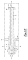
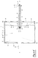
- the cleaning system furthermore comprises the previously mentioned removable closure means that the user inserts into the supply duct 5 through a central bore 20 passing through the cover 18 closing the inlet of the supply duct 5, to seal the inlets 14 of the supply tubes 6 hermetically connected to the supply duct.
- this removable means comprises a rod 24 whose end portion comprises seals 25 which, once the rod 24 is in place in the feed duct 5, hermetically seals the radial holes 13 of the exhaust duct 8 located downstream of the O-ring with respect to the direction of fluid flow in the supply pipe 5.
- the end portion of the rod 24 further comprises a clamp 26 which can be actuated by the user via an external handle 27 of the quarter-turn type to radially reinforce the seal 25.
- the cleaning system comprises cleaning lines 28 each connected to a tube of supply 6 downstream of its input.
- Each cleaning pipe 28 is accessible at one of the ends of the heat exchanger 1, through the circular windows 33 of the corresponding transverse wall 32.
- each cleaning pipe 28 is arranged to be connected to a external source of cleaning fluid (not shown) to allow the injection of this fluid into the corresponding feed tube 6.
- Each cleaning line 28 comprises an elbow tube 29 connected at its outlet radially to the wall of the corresponding supply tube 6.
- the inlet of the cleaning line 28 comprises a male or female connector 30 intended to cooperate with a connector connected to the outlet of the cleaning fluid source.
- a rigid plane support 31 is integral with each cleaning line 28 near its end and the corresponding feed tube 6.
- the supply and evacuation tubes 6 are arranged so that one half of the set of tubes respectively supply 6 and discharge 9 is accessible through the circular windows 33 of the one of the transverse end walls 32 of the heat exchanger 1, the remaining half of this set of tubes respectively supply 6 and discharge 9 being accessible through the circular windows 33 of the other end transverse wall 32 of the heat exchanger 1.
- the cleaning system according to the invention makes it possible to detect very rapidly losses of flow of coolant circulating in the partially clogged channel (s) 4. Indeed, when one of the channels 4 is partially clogged, the temperature sensor 21 supplies the acquisition unit 22 with a temperature signal which is transmitted to the external processing unit 23 providing information identifying the channel 4 partially obstructed, for example by display.
- the cleaning lines 28 and the removable closure means make it possible to inject cleaning fluid only into the channels 4 which are the subject of cleaning and / or descaling, significantly increasing the efficiency of the cleaning of the channels. The consumption of cleaning fluid and the injection volume of the latter in the channels 4 to be cleaned are therefore optimized, particularly avoiding any overconsumption of cleaning fluid.
Landscapes
- Engineering & Computer Science (AREA)
- Mechanical Engineering (AREA)
- General Engineering & Computer Science (AREA)
- Chemical & Material Sciences (AREA)
- Combustion & Propulsion (AREA)
- Physics & Mathematics (AREA)
- Thermal Sciences (AREA)
- Heat-Exchange Devices With Radiators And Conduit Assemblies (AREA)
Priority Applications (1)
| Application Number | Priority Date | Filing Date | Title |
|---|---|---|---|
| EP16305302.8A EP3220089B1 (de) | 2016-03-18 | 2016-03-18 | System und verfahren zum reinigen eines wärmetauschers |
Applications Claiming Priority (1)
| Application Number | Priority Date | Filing Date | Title |
|---|---|---|---|
| EP16305302.8A EP3220089B1 (de) | 2016-03-18 | 2016-03-18 | System und verfahren zum reinigen eines wärmetauschers |
Publications (2)
| Publication Number | Publication Date |
|---|---|
| EP3220089A1 true EP3220089A1 (de) | 2017-09-20 |
| EP3220089B1 EP3220089B1 (de) | 2018-08-08 |
Family
ID=55589785
Family Applications (1)
| Application Number | Title | Priority Date | Filing Date |
|---|---|---|---|
| EP16305302.8A Active EP3220089B1 (de) | 2016-03-18 | 2016-03-18 | System und verfahren zum reinigen eines wärmetauschers |
Country Status (1)
| Country | Link |
|---|---|
| EP (1) | EP3220089B1 (de) |
Cited By (1)
| Publication number | Priority date | Publication date | Assignee | Title |
|---|---|---|---|---|
| CN115682780A (zh) * | 2022-11-30 | 2023-02-03 | 华能烟台八角热电有限公司 | 一种高温管式换热器及其清洗方法 |
Citations (4)
| Publication number | Priority date | Publication date | Assignee | Title |
|---|---|---|---|---|
| US3187809A (en) * | 1963-01-11 | 1965-06-08 | Inta Roto Machine Company Inc | Heat-exchange roll and method of making |
| DE3315376C1 (de) * | 1983-04-26 | 1984-08-16 | Mannesmann AG, 4000 Düsseldorf | Stranggiessrolle |
| US5292298A (en) * | 1993-01-06 | 1994-03-08 | Roll Service Incorporated | Heat transfer roll |
| WO2015181691A1 (en) * | 2014-05-26 | 2015-12-03 | Cos.T.A. S.R.L. | Thermostatically controlled cylinder for heat treatments, method for making said cylinder and system comprising said cylinder |
-
2016
- 2016-03-18 EP EP16305302.8A patent/EP3220089B1/de active Active
Patent Citations (4)
| Publication number | Priority date | Publication date | Assignee | Title |
|---|---|---|---|---|
| US3187809A (en) * | 1963-01-11 | 1965-06-08 | Inta Roto Machine Company Inc | Heat-exchange roll and method of making |
| DE3315376C1 (de) * | 1983-04-26 | 1984-08-16 | Mannesmann AG, 4000 Düsseldorf | Stranggiessrolle |
| US5292298A (en) * | 1993-01-06 | 1994-03-08 | Roll Service Incorporated | Heat transfer roll |
| WO2015181691A1 (en) * | 2014-05-26 | 2015-12-03 | Cos.T.A. S.R.L. | Thermostatically controlled cylinder for heat treatments, method for making said cylinder and system comprising said cylinder |
Cited By (1)
| Publication number | Priority date | Publication date | Assignee | Title |
|---|---|---|---|---|
| CN115682780A (zh) * | 2022-11-30 | 2023-02-03 | 华能烟台八角热电有限公司 | 一种高温管式换热器及其清洗方法 |
Also Published As
| Publication number | Publication date |
|---|---|
| EP3220089B1 (de) | 2018-08-08 |
Similar Documents
| Publication | Publication Date | Title |
|---|---|---|
| EP0694356B1 (de) | Verfahren und Einrichtung zur Korrektion der Bombierung der Stranggiesswalzen für Metallband | |
| FR3019772A1 (fr) | Dispositif et procede servant a mesurer l'humidite presente dans des moules de coulee sous pression | |
| CH643481A5 (fr) | Dispositif pour le calibrage d'un tube en matiere plastique produit par extrusion. | |
| FR2564745A1 (fr) | Dispositif pour epurer mecaniquement des liquides | |
| EP3220089B1 (de) | System und verfahren zum reinigen eines wärmetauschers | |
| FR2564197A1 (fr) | Appareil de transmission d'un rayonnement | |
| FR3119659A1 (fr) | Dispositif d'obturation mobile pour obturer une conduite | |
| FR2957999A1 (fr) | Piston avec un conduit sous joint | |
| EP0014140B1 (de) | Vorrichtung zum Abkühlen eines sich longitudinal fortbewegenden länglichen Gegenstandes | |
| EP0029792B1 (de) | Vorrichtung zum kontinuierlichen Aufbringen einer Beschichtung auf die Aussenfläche eines Profils | |
| FR2558592A1 (fr) | Procedes et dispositifs pour verifier en continu l'etancheite des tubes extrudes en matiere plastique | |
| WO2016146930A1 (fr) | Échangeur de chaleur a blocs, son procédé de mise en oeuvre et bloc d'échange thermique appartenant a un tel échangeur | |
| FR2708347A1 (fr) | Chambre de mesure, notamment pour le contrôle de l'eau d'une piscine. | |
| EP0636720A1 (de) | Vorrichtung zur thermischen Behandlung von laufenden Garnen | |
| FR2780764A1 (fr) | Procede de montage d'un raccord a l'extremite d'un tube et nouveau type de raccord permettant sa mise en oeuvre | |
| WO2016198787A1 (fr) | Échangeur de chaleur tubulaire à tubes de graphite comprenant un organe de contrôle de l'encrassement, son procédé de mise en œuvre et son procédé de montage | |
| WO2013107830A1 (fr) | Dispositif de circulation d'un fluide caloporteur autour d'un tuyau de transport de fluide, kit pour la réalisation et procédé d'installation d'un tel dispositif | |
| FR2687219A1 (fr) | Dispositif tranquilliseur pour le comptage du debit de fluides. | |
| WO2022013241A1 (fr) | Système à rotor de mesure du débit d'un fluide comportant du liquide, et équipement associé | |
| FR3068030A1 (fr) | Dispositif de captation de particules ferreuses comprenant une enceinte dans laquelle est present au moins un barreau aimante amovible | |
| EP0559564A1 (de) | Progressives Expansionsventil | |
| EP2213917A1 (de) | Selbstreinigender Kugelhahn für einen Partikel enthaltenden Wasserkreislauf | |
| WO2003071203A1 (fr) | Installation de délivrance d'un produit congelé et son procédé d'utilisation | |
| WO1988003246A1 (fr) | Installation d'enfutage | |
| EP0877222A2 (de) | Anlage zum Druckspritzen von Fluiden in einem Plattenwärmetauscher und Verfahren zur Reinigung dieser Druckspritzanlage |
Legal Events
| Date | Code | Title | Description |
|---|---|---|---|
| PUAI | Public reference made under article 153(3) epc to a published international application that has entered the european phase |
Free format text: ORIGINAL CODE: 0009012 |
|
| STAA | Information on the status of an ep patent application or granted ep patent |
Free format text: STATUS: THE APPLICATION HAS BEEN PUBLISHED |
|
| AK | Designated contracting states |
Kind code of ref document: A1 Designated state(s): AL AT BE BG CH CY CZ DE DK EE ES FI FR GB GR HR HU IE IS IT LI LT LU LV MC MK MT NL NO PL PT RO RS SE SI SK SM TR |
|
| AX | Request for extension of the european patent |
Extension state: BA ME |
|
| STAA | Information on the status of an ep patent application or granted ep patent |
Free format text: STATUS: REQUEST FOR EXAMINATION WAS MADE |
|
| 17P | Request for examination filed |
Effective date: 20171114 |
|
| RBV | Designated contracting states (corrected) |
Designated state(s): AL AT BE BG CH CY CZ DE DK EE ES FI FR GB GR HR HU IE IS IT LI LT LU LV MC MK MT NL NO PL PT RO RS SE SI SK SM TR |
|
| GRAP | Despatch of communication of intention to grant a patent |
Free format text: ORIGINAL CODE: EPIDOSNIGR1 |
|
| STAA | Information on the status of an ep patent application or granted ep patent |
Free format text: STATUS: GRANT OF PATENT IS INTENDED |
|
| RIC1 | Information provided on ipc code assigned before grant |
Ipc: F28G 9/00 20060101ALI20171212BHEP Ipc: F28G 15/00 20060101ALI20171212BHEP Ipc: F28F 5/02 20060101ALI20171212BHEP Ipc: F28F 27/02 20060101ALI20171212BHEP Ipc: F28D 11/02 20060101AFI20171212BHEP |
|
| INTG | Intention to grant announced |
Effective date: 20180109 |
|
| GRAS | Grant fee paid |
Free format text: ORIGINAL CODE: EPIDOSNIGR3 |
|
| GRAA | (expected) grant |
Free format text: ORIGINAL CODE: 0009210 |
|
| STAA | Information on the status of an ep patent application or granted ep patent |
Free format text: STATUS: THE PATENT HAS BEEN GRANTED |
|
| AK | Designated contracting states |
Kind code of ref document: B1 Designated state(s): AL AT BE BG CH CY CZ DE DK EE ES FI FR GB GR HR HU IE IS IT LI LT LU LV MC MK MT NL NO PL PT RO RS SE SI SK SM TR |
|
| REG | Reference to a national code |
Ref country code: GB Ref legal event code: FG4D Free format text: NOT ENGLISH |
|
| REG | Reference to a national code |
Ref country code: CH Ref legal event code: EP Ref country code: AT Ref legal event code: REF Ref document number: 1027491 Country of ref document: AT Kind code of ref document: T Effective date: 20180815 |
|
| REG | Reference to a national code |
Ref country code: IE Ref legal event code: FG4D Free format text: LANGUAGE OF EP DOCUMENT: FRENCH |
|
| REG | Reference to a national code |
Ref country code: DE Ref legal event code: R096 Ref document number: 602016004609 Country of ref document: DE |
|
| REG | Reference to a national code |
Ref country code: NL Ref legal event code: MP Effective date: 20180808 |
|
| REG | Reference to a national code |
Ref country code: LT Ref legal event code: MG4D |
|
| REG | Reference to a national code |
Ref country code: AT Ref legal event code: MK05 Ref document number: 1027491 Country of ref document: AT Kind code of ref document: T Effective date: 20180808 |
|
| PG25 | Lapsed in a contracting state [announced via postgrant information from national office to epo] |
Ref country code: NO Free format text: LAPSE BECAUSE OF FAILURE TO SUBMIT A TRANSLATION OF THE DESCRIPTION OR TO PAY THE FEE WITHIN THE PRESCRIBED TIME-LIMIT Effective date: 20181108 Ref country code: GR Free format text: LAPSE BECAUSE OF FAILURE TO SUBMIT A TRANSLATION OF THE DESCRIPTION OR TO PAY THE FEE WITHIN THE PRESCRIBED TIME-LIMIT Effective date: 20181109 Ref country code: AT Free format text: LAPSE BECAUSE OF FAILURE TO SUBMIT A TRANSLATION OF THE DESCRIPTION OR TO PAY THE FEE WITHIN THE PRESCRIBED TIME-LIMIT Effective date: 20180808 Ref country code: BG Free format text: LAPSE BECAUSE OF FAILURE TO SUBMIT A TRANSLATION OF THE DESCRIPTION OR TO PAY THE FEE WITHIN THE PRESCRIBED TIME-LIMIT Effective date: 20181108 Ref country code: IS Free format text: LAPSE BECAUSE OF FAILURE TO SUBMIT A TRANSLATION OF THE DESCRIPTION OR TO PAY THE FEE WITHIN THE PRESCRIBED TIME-LIMIT Effective date: 20181208 Ref country code: NL Free format text: LAPSE BECAUSE OF FAILURE TO SUBMIT A TRANSLATION OF THE DESCRIPTION OR TO PAY THE FEE WITHIN THE PRESCRIBED TIME-LIMIT Effective date: 20180808 Ref country code: FI Free format text: LAPSE BECAUSE OF FAILURE TO SUBMIT A TRANSLATION OF THE DESCRIPTION OR TO PAY THE FEE WITHIN THE PRESCRIBED TIME-LIMIT Effective date: 20180808 Ref country code: LT Free format text: LAPSE BECAUSE OF FAILURE TO SUBMIT A TRANSLATION OF THE DESCRIPTION OR TO PAY THE FEE WITHIN THE PRESCRIBED TIME-LIMIT Effective date: 20180808 Ref country code: RS Free format text: LAPSE BECAUSE OF FAILURE TO SUBMIT A TRANSLATION OF THE DESCRIPTION OR TO PAY THE FEE WITHIN THE PRESCRIBED TIME-LIMIT Effective date: 20180808 Ref country code: PL Free format text: LAPSE BECAUSE OF FAILURE TO SUBMIT A TRANSLATION OF THE DESCRIPTION OR TO PAY THE FEE WITHIN THE PRESCRIBED TIME-LIMIT Effective date: 20180808 Ref country code: SE Free format text: LAPSE BECAUSE OF FAILURE TO SUBMIT A TRANSLATION OF THE DESCRIPTION OR TO PAY THE FEE WITHIN THE PRESCRIBED TIME-LIMIT Effective date: 20180808 |
|
| PG25 | Lapsed in a contracting state [announced via postgrant information from national office to epo] |
Ref country code: AL Free format text: LAPSE BECAUSE OF FAILURE TO SUBMIT A TRANSLATION OF THE DESCRIPTION OR TO PAY THE FEE WITHIN THE PRESCRIBED TIME-LIMIT Effective date: 20180808 Ref country code: LV Free format text: LAPSE BECAUSE OF FAILURE TO SUBMIT A TRANSLATION OF THE DESCRIPTION OR TO PAY THE FEE WITHIN THE PRESCRIBED TIME-LIMIT Effective date: 20180808 Ref country code: HR Free format text: LAPSE BECAUSE OF FAILURE TO SUBMIT A TRANSLATION OF THE DESCRIPTION OR TO PAY THE FEE WITHIN THE PRESCRIBED TIME-LIMIT Effective date: 20180808 |
|
| PG25 | Lapsed in a contracting state [announced via postgrant information from national office to epo] |
Ref country code: EE Free format text: LAPSE BECAUSE OF FAILURE TO SUBMIT A TRANSLATION OF THE DESCRIPTION OR TO PAY THE FEE WITHIN THE PRESCRIBED TIME-LIMIT Effective date: 20180808 Ref country code: IT Free format text: LAPSE BECAUSE OF FAILURE TO SUBMIT A TRANSLATION OF THE DESCRIPTION OR TO PAY THE FEE WITHIN THE PRESCRIBED TIME-LIMIT Effective date: 20180808 Ref country code: CZ Free format text: LAPSE BECAUSE OF FAILURE TO SUBMIT A TRANSLATION OF THE DESCRIPTION OR TO PAY THE FEE WITHIN THE PRESCRIBED TIME-LIMIT Effective date: 20180808 Ref country code: RO Free format text: LAPSE BECAUSE OF FAILURE TO SUBMIT A TRANSLATION OF THE DESCRIPTION OR TO PAY THE FEE WITHIN THE PRESCRIBED TIME-LIMIT Effective date: 20180808 |
|
| REG | Reference to a national code |
Ref country code: DE Ref legal event code: R097 Ref document number: 602016004609 Country of ref document: DE |
|
| PG25 | Lapsed in a contracting state [announced via postgrant information from national office to epo] |
Ref country code: SK Free format text: LAPSE BECAUSE OF FAILURE TO SUBMIT A TRANSLATION OF THE DESCRIPTION OR TO PAY THE FEE WITHIN THE PRESCRIBED TIME-LIMIT Effective date: 20180808 Ref country code: SM Free format text: LAPSE BECAUSE OF FAILURE TO SUBMIT A TRANSLATION OF THE DESCRIPTION OR TO PAY THE FEE WITHIN THE PRESCRIBED TIME-LIMIT Effective date: 20180808 Ref country code: DK Free format text: LAPSE BECAUSE OF FAILURE TO SUBMIT A TRANSLATION OF THE DESCRIPTION OR TO PAY THE FEE WITHIN THE PRESCRIBED TIME-LIMIT Effective date: 20180808 |
|
| PLBE | No opposition filed within time limit |
Free format text: ORIGINAL CODE: 0009261 |
|
| STAA | Information on the status of an ep patent application or granted ep patent |
Free format text: STATUS: NO OPPOSITION FILED WITHIN TIME LIMIT |
|
| 26N | No opposition filed |
Effective date: 20190509 |
|
| PG25 | Lapsed in a contracting state [announced via postgrant information from national office to epo] |
Ref country code: ES Free format text: LAPSE BECAUSE OF FAILURE TO SUBMIT A TRANSLATION OF THE DESCRIPTION OR TO PAY THE FEE WITHIN THE PRESCRIBED TIME-LIMIT Effective date: 20180808 |
|
| PG25 | Lapsed in a contracting state [announced via postgrant information from national office to epo] |
Ref country code: SI Free format text: LAPSE BECAUSE OF FAILURE TO SUBMIT A TRANSLATION OF THE DESCRIPTION OR TO PAY THE FEE WITHIN THE PRESCRIBED TIME-LIMIT Effective date: 20180808 |
|
| PG25 | Lapsed in a contracting state [announced via postgrant information from national office to epo] |
Ref country code: MC Free format text: LAPSE BECAUSE OF FAILURE TO SUBMIT A TRANSLATION OF THE DESCRIPTION OR TO PAY THE FEE WITHIN THE PRESCRIBED TIME-LIMIT Effective date: 20180808 |
|
| REG | Reference to a national code |
Ref country code: CH Ref legal event code: PL |
|
| PG25 | Lapsed in a contracting state [announced via postgrant information from national office to epo] |
Ref country code: LU Free format text: LAPSE BECAUSE OF NON-PAYMENT OF DUE FEES Effective date: 20190318 |
|
| REG | Reference to a national code |
Ref country code: BE Ref legal event code: MM Effective date: 20190331 |
|
| PG25 | Lapsed in a contracting state [announced via postgrant information from national office to epo] |
Ref country code: IE Free format text: LAPSE BECAUSE OF NON-PAYMENT OF DUE FEES Effective date: 20190318 Ref country code: LI Free format text: LAPSE BECAUSE OF NON-PAYMENT OF DUE FEES Effective date: 20190331 Ref country code: CH Free format text: LAPSE BECAUSE OF NON-PAYMENT OF DUE FEES Effective date: 20190331 |
|
| PG25 | Lapsed in a contracting state [announced via postgrant information from national office to epo] |
Ref country code: BE Free format text: LAPSE BECAUSE OF NON-PAYMENT OF DUE FEES Effective date: 20190331 |
|
| PG25 | Lapsed in a contracting state [announced via postgrant information from national office to epo] |
Ref country code: TR Free format text: LAPSE BECAUSE OF FAILURE TO SUBMIT A TRANSLATION OF THE DESCRIPTION OR TO PAY THE FEE WITHIN THE PRESCRIBED TIME-LIMIT Effective date: 20180808 |
|
| PG25 | Lapsed in a contracting state [announced via postgrant information from national office to epo] |
Ref country code: PT Free format text: LAPSE BECAUSE OF FAILURE TO SUBMIT A TRANSLATION OF THE DESCRIPTION OR TO PAY THE FEE WITHIN THE PRESCRIBED TIME-LIMIT Effective date: 20181208 Ref country code: MT Free format text: LAPSE BECAUSE OF FAILURE TO SUBMIT A TRANSLATION OF THE DESCRIPTION OR TO PAY THE FEE WITHIN THE PRESCRIBED TIME-LIMIT Effective date: 20180808 |
|
| GBPC | Gb: european patent ceased through non-payment of renewal fee |
Effective date: 20200318 |
|
| PG25 | Lapsed in a contracting state [announced via postgrant information from national office to epo] |
Ref country code: GB Free format text: LAPSE BECAUSE OF NON-PAYMENT OF DUE FEES Effective date: 20200318 |
|
| PG25 | Lapsed in a contracting state [announced via postgrant information from national office to epo] |
Ref country code: CY Free format text: LAPSE BECAUSE OF FAILURE TO SUBMIT A TRANSLATION OF THE DESCRIPTION OR TO PAY THE FEE WITHIN THE PRESCRIBED TIME-LIMIT Effective date: 20180808 |
|
| PG25 | Lapsed in a contracting state [announced via postgrant information from national office to epo] |
Ref country code: HU Free format text: LAPSE BECAUSE OF FAILURE TO SUBMIT A TRANSLATION OF THE DESCRIPTION OR TO PAY THE FEE WITHIN THE PRESCRIBED TIME-LIMIT; INVALID AB INITIO Effective date: 20160318 |
|
| PG25 | Lapsed in a contracting state [announced via postgrant information from national office to epo] |
Ref country code: MK Free format text: LAPSE BECAUSE OF FAILURE TO SUBMIT A TRANSLATION OF THE DESCRIPTION OR TO PAY THE FEE WITHIN THE PRESCRIBED TIME-LIMIT Effective date: 20180808 |
|
| P01 | Opt-out of the competence of the unified patent court (upc) registered |
Effective date: 20230522 |
|
| PGFP | Annual fee paid to national office [announced via postgrant information from national office to epo] |
Ref country code: FR Payment date: 20260305 Year of fee payment: 11 |
|
| PGFP | Annual fee paid to national office [announced via postgrant information from national office to epo] |
Ref country code: DE Payment date: 20260410 Year of fee payment: 11 |