EP3220214A9 - Dispositif de réglage de paramètre de commande et procédé de réglage de paramètre de commande - Google Patents
Dispositif de réglage de paramètre de commande et procédé de réglage de paramètre de commande Download PDFInfo
- Publication number
- EP3220214A9 EP3220214A9 EP17160348.3A EP17160348A EP3220214A9 EP 3220214 A9 EP3220214 A9 EP 3220214A9 EP 17160348 A EP17160348 A EP 17160348A EP 3220214 A9 EP3220214 A9 EP 3220214A9
- Authority
- EP
- European Patent Office
- Prior art keywords
- gain
- proportional speed
- stabilization time
- speed gain
- servo motor
- Prior art date
- Legal status (The legal status is an assumption and is not a legal conclusion. Google has not performed a legal analysis and makes no representation as to the accuracy of the status listed.)
- Granted
Links
Images

Classifications
-
- H—ELECTRICITY
- H02—GENERATION; CONVERSION OR DISTRIBUTION OF ELECTRIC POWER
- H02P—CONTROL OR REGULATION OF ELECTRIC MOTORS, ELECTRIC GENERATORS OR DYNAMO-ELECTRIC CONVERTERS; CONTROLLING TRANSFORMERS, REACTORS OR CHOKE COILS
- H02P29/00—Arrangements for regulating or controlling electric motors, appropriate for both AC and DC motors
-
- G—PHYSICS
- G05—CONTROLLING; REGULATING
- G05B—CONTROL OR REGULATING SYSTEMS IN GENERAL; FUNCTIONAL ELEMENTS OF SUCH SYSTEMS; MONITORING OR TESTING ARRANGEMENTS FOR SUCH SYSTEMS OR ELEMENTS
- G05B6/00—Internal feedback arrangements for obtaining particular characteristics, e.g. proportional, integral or differential
- G05B6/02—Internal feedback arrangements for obtaining particular characteristics, e.g. proportional, integral or differential electric
-
- G—PHYSICS
- G05—CONTROLLING; REGULATING
- G05B—CONTROL OR REGULATING SYSTEMS IN GENERAL; FUNCTIONAL ELEMENTS OF SUCH SYSTEMS; MONITORING OR TESTING ARRANGEMENTS FOR SUCH SYSTEMS OR ELEMENTS
- G05B13/00—Adaptive control systems, i.e. systems automatically adjusting themselves to have a performance which is optimum according to some preassigned criterion
- G05B13/02—Adaptive control systems, i.e. systems automatically adjusting themselves to have a performance which is optimum according to some preassigned criterion electric
- G05B13/0205—Adaptive control systems, i.e. systems automatically adjusting themselves to have a performance which is optimum according to some preassigned criterion electric not using a model or a simulator of the controlled system
- G05B13/024—Adaptive control systems, i.e. systems automatically adjusting themselves to have a performance which is optimum according to some preassigned criterion electric not using a model or a simulator of the controlled system in which a parameter or coefficient is automatically adjusted to optimise the performance
Definitions
- the present invention relates to a control device for tuning a servo motor and a corresponding method for tuning a servo motor.
- a servo motor for moving a load is controlled by a controller for controlling, using a drive current or control signal, the servo motor which drives a mechanical load.
- the controller and the servo motor are implemented as a closed loop system.
- the controller generates a control signal instructing the motor to move the mechanical load.
- the control signal applied depends on the motion application type (motor is moved to a desired position at a desired velocity, motor speed is varied, or the torque applied is varied).
- a feedback signal from the motor to the controller indicates the current actual state (e. g., position, velocity, etc.) of the motor and/or load.
- the feedback signal can be originated by an encoder or a resolver attached to the motor, by measuring the load position, or by estimation.
- the controller compares the actual position of the load (feedback signal) with the instructed target position (control signal), and adjusts the newly calculated control signal as needed to minimize the differences between both signals (actual and target positions). This is continued until the target position is reached.
- the motor/load accelerates/decelerates, i.e. changes speed, in order to reach the target position.
- the motor/load requires a so-called stabilization time which can be defined as the period of time required by the motor to reach a halt state of the motor/load after having arrived at the target position.
- gain affects the accuracy (i.e. how close to the desired speed, or position is the motor's actual speed or position). A high gain will allow an accurate movement.
- the servo motor is tuned, which may include the tuning of the servo motor's proportional speed gain.
- the controller may implement for example a PID filter for calculating the control signal that is applied to the motor.
- parameters of the PID filter are tuned. These parameters may include the proportional speed gain, a proportional position gain, a velocity control gain, the torque command filter and a position command filter.
- the proportional speed gain may be understood as the primary parameter.
- the responsiveness of the servo motor is determined by the proportional speed gain.
- United States Patent Application 5,153,807A discloses such a self-tuning controller apparatus, which uses fuzzy logic rules to map human knowledge in order to perform control parameter tuning based on characteristic variables.
- United States Patent 5,213,077 is an attempt to minimize this combinatorial explosion and reduce the number of inference rules. More specifically, this document discloses a gain adjusting device for a PID controller, in which a plurality of characteristic variables concerning the rotational speed are detected so as to be used for inference and the plurality of characteristic variables are divided into a plurality of sets. Groups of rules each indicating the relationship between the characteristic variables corresponding to each set and an amount of gain adjustment, as well as the relationship between the magnitude of the characteristic variable corresponding to each set and the degree of adoption of the amount of gain adjustment, are stored. The amount of gain adjustment for each set is inferred on the basis of the characteristic variables detected and each group of rules.
- an amount of gain to be adjusted is determined by calculating a weighted average value of the result of inference of the amount of gain adjustment with the degree of adoption set as the weight. This amount of gain to be adjusted is set in the PID controller.
- the effectiveness of the respective tuning approach depends on the quality of the inference rules. Moreover, it is difficult to obtain inference rules of high quality and to reduce them to a corresponding control program. Furthermore, the obtained inference rules may not cover all possible scenarios, so that there is a lack in versatility.
- the control device comprises a calculation unit configured to determine a current proportional speed gain, which is a proportiona speed of a current tuning iteration of the servo motor and to calculate a stabilization time ratio based on a current stabilization time of the servo motor and a target stabilization time, a determination unit configured to select a gain determination process based on the calculated stabilization time ratio, and to determine a next proportional speed gain using the selected gain determination process, the next proportional speed gain being a (target) proportional speed gain of the next tuning iteration following the current tuning iteration, wherein the determination unit is configured to select a skip step gain determination process, in which the next proportional speed gain is determined by a first calculation rule that is dependent on the calculated stabilization time ratio, if the stabilization time ratio is equal to or greater than a predetermined reference value, and to select a one step gain determination process, in which the next proportional speed gain is determined
- the calculation unit may be further configured to update parameters of the servo motor according to the determined next proportional speed gain, and a control unit configured to generate a control signal for controlling the servo motor for driving a load based on the updated parameters.
- gain affects the accuracy of the servo motor.
- the gain in particular the proportional speed gain of the servo motor, is responsible for how close the motor will come to the desired speed or position. A high gain will allow an accurate movement. Further parameters of the servo motor depend on the proportional speed gain and are determined accordingly.
- the proportional speed gain is adapted in a closed loop system provided by the control device.
- the control device may implement for example a PID filter for calculating the control signal that is applied to the motor. If the proportional speed gain K n is updated due to this closed loop system, the parameters which depend on K n will also be updated.
- a target stabilization time may be input to the control device, for example by a user input.
- the target stabilization time may define the time which is acceptable as the period of time required by the motor to reach a predetermined state, such as a halt state of the motor/load after having arrived at the target position.
- the target position is the position which should be reached by the motor/load according to a user input or control of the servo motor.
- the proportional speed gain or more precisely, the next proportional speed gain, is calculated based on a stabilization time ratio.
- the stabilization time ratio defines how far away the current stabilization time is from the target stabilization time.
- a gain determination process is selected.
- the next proportional speed gain K n+1 of the next tuning iteration is calculated.
- the parameters depending on K n may then be updated according to K n+1 .
- the updated parameters, including the next proportional speed gain, are included into (i.e. determine) a control signal.
- the control unit then sends the control signal to the motor for continuing the movement according to the updated parameters.
- motor and servo motor are used synonymously.
- a movement of the load includes a movement of the motor and vice versa.
- the calculation unit is adapted to initially determine the current proportional speed gain as a fixed initial proportional speed gain based on a user input.
- the control device does not have any information with respect to the current proportional speed gain.
- the initial value of the proportional speed gain i.e. the value for starting the tuning, is set to a fixed and low value.
- the proportional speed gain is updated.
- control device comprises a graphical user interface for receiving the user input.
- the graphical user interface may also provide the possibility to start the whole tuning mechanism and/or to input further parameters like the target stabilization time.
- the calculation unit is adapted to initially determine the current proportional speed gain based on an inertia estimation of the servo motor.
- the inertia estimation and the calculation of the current proportional speed gain may be done in the drive control of the servo motor and may be provided to the control device.
- the user may choose whether the calculation unit receives the initial proportional speed gain from a user input via the graphical user interface or whether the calculation unit receives the initial proportional speed gain based on an inertia estimation of the servo motor. Both embodiments may also be combined.
- control device further comprises a detection unit configured to detect whether vibrations affect the servo motor and/or the load and to send a signal to the servo motor for eliminating the detected vibrations.
- Vibrations or other abnormal activities of the motor and/or load may occur during the movement of the motor and/or load. Such vibrations or resonances may happen at some point during the movement and may be present during the calculation of the next proportional speed gain by the determination unit.
- the detection unit may monitor the servo motor.
- the detection unit is configured to detect a vibration if a deviation of the motor speed between a motor speed command and a motor speed feedback is larger than an acceptable criterion (i.e. larger than a predetermined value).
- the detection unit may determine whether there are any vibrations based on the motor speed command and the motor speed feedback, If the difference between these values is larger than a predefined value, the detection may take this to indicate vibrations.
- the detection unit determines whether there are any vibrations based on the torque command value which is calculated from the speed deviation between the motor speed command and the motor speed feedback.
- an acceptable criterion may be given as % of rated torque of the motor.
- the acceptable criterion may be 3% of rated torque of the motor.
- the detection unit is configured to detect a vibration if the occurrence number of the zero-cross for the deviation of motor speed is within an acceptable (predetermined) range.
- vibrations may be detected by monitoring zero-crossings of the deviation of the motor speed.
- the detection unit may detect a vibration if the occurrence numbers of the zero-cross of the torque command value, which is calculated from the speed deviation between the motor speed command and the motor speed feedback, is within an predetermined range.
- the detection unit is configured to compare the current proportional speed gain and the next proportional speed gain.
- the detection unit may confirm whether these vibrations can be eliminated by applying filters by comparing the current proportional speed gain and the next proportional speed gain.
- the current proportional speed gain may be directly derived from the motor. If the current proportional speed gain is larger than the newly calculated next proportional speed gain, the detection unit can confirm that there are vibrations and send a signal to the motor for eliminating these vibrations. The elimination may be done directly in the motor by applying for example a filter to remove resonances in the control signal.
- the detection unit is configured to send a signal to the control unit to generate the control signal based on the previous parameters in case of detected vibrations.
- the detection unit may instruct the control unit to use the previous parameters, i.e. not the updated parameters, for the generation of the control signal or abort the tuning process after a predetermined number of iterations, and to indicate the failure of the operation according to the user input.
- the detection unit is configured to send a signal to the determination unit to determine the next proportional speed gain after the detected vibrations are eliminated.
- the detection unit may send a signal to the determination unit for continuing the determination of the next proportional speed gain and update of the further parameters.
- the calculation unit is configured to calculate the stabilization time ratio as the quotient between the current stabilization time and the target stabilization time.
- the calculation unit, the determination unit and the control unit are configured to repeat their functions until the current stabilization time is equal to or lower than the target stabilization time.
- the stabilization time ratio is equal to one or less than one, the target stabilization time has been reached and the acceptance criteria for the movement of the motor/load have been reached. At this point, the tuning of the servo motor will be ended.
- the determination unit is configured to apply a skip step gain determination process as the selected gain determination process if the stabilization time ratio is above a predetermined reference value.
- the determination unit applies the skip step gain determination process.
- the skip step gain determination process results in a large increase of the proportional speed gain.
- the predetermined reference value may be for example ⁇ 2 ⁇ .
- ⁇ may be a predefined coefficient which can be set according to the used servo motor and the characteristics of the used servo motor.
- ⁇ may be considered as a "tuning" factor for the skip step gain determination process.
- ⁇ may be set accordingly, for example to 2 or about 2.
- the determination unit is configured to apply a one step gain determination process as the selected gain determination process if the stabilization time ratio is below a predetermined reference value.
- the determination unit applies a one step gain determination process which results in a smaller increase of the proportional speed gain than when the skip step gain determination process is applied.
- the predetermined reference value is the same as for the skip step gain determination process, and may be for example ⁇ 2 ⁇ .
- the one step gain determination process defines that the next proportional speed gain is calculated as a function independent on the stabilization time ratio.
- the determination unit is configured to compare the next proportional speed gain of the one step gain determination process and the next proportional speed gain of the skip step gain determination process, and, if the next proportional speed gain of the one step gain determination process is larger than the next proportional speed gain of the skip step gain determination process, the determination unit is configured to use the next proportional speed gain of the one step gain determination process.
- the determination unit In addition to the determination of the next proportional speed gain based on the selected gain determination process, the determination unit provides a safety feature.
- the determination unit calculates the next proportional speed gain of the one step gain determination process and the next proportional speed gain of the skip step gain determination process and compares the two results. If the determination unit has selected the skip step gain determination process but the next proportional speed gain according to the one step gain determination process is larger than the next proportional speed gain according to the skip step gain determination process, the determination unit is configured to override the first result of the next proportional speed gain and use next proportional speed gain according to the one step gain determination process. In this way, it can be avoided that the skip step gain determination process is used although the one step gain determination process would be more suitable.
- the parameters are at least one of a proportional position gain, a velocity control gain, a torque command filter and a position command filter.
- the invention relates to a method for tuning a servo motor.
- the method comprises the following steps:
- the invention relates to a computer program product comprising a program code for executing the above-described method for tuning a servo motor when run on at least one computer.
- a computer program product such as a computer program means, may be embodied as a memory card, USB stick, CD-ROM, DVD or as a file which may be downloaded from a server in a network.
- a file may be provided by transferring the file comprising the computer program product from a wireless communication network.
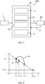
- Fig. 1 shows a servo motor system 100 comprising a servo motor 20 and a control device 10 for tuning and controlling the servo motor 20.
- various parameters such as proportional and integral gain values or cutoff frequency for command filters are determined. The determined parameters are then used for the control of the servo motor.
- the tuning of the servo motor 20 is performed iteratively. More specfically, at every tuning iteration, the servo motor 20 is brought from an initial state to a target state.
- the initial state may be a rest state in which the servo motor 20 rests at a predetermined initial position or a state in which the servo motor 20 moves at a predetermined initial angular velocity.
- the target state may be a rest state in which the servo motor 20 rests at a predetermined target position or a state in which the servo motor 20 moves at a predetermined target angular velocity.
- the time period that it takes to bring the servo motor 20 from the intial state to the target state may be referred to as "stabilization time".
- the beginning of the stabilization time may be defined as the time when the servo motor 20 leaves the initial state, or alternatively, the time when the control device 10 receives as a command signal for controlling the servo motor 20 to bring it into the target state.
- the end of the stabilization time may be defined as the time when the servo motor 20 has reached a steady target state, in particular after any overshooting has been compensated.
- the control device 10 can receive a user input 1, which can be input via a graphical user interface.
- the user input 1 can comprise information with respect to a movement of the servo motor 20, which can move a load (not shown).
- the control device 10 sends a control signal 2 to the servo motor 20.
- the servo motor 20 sends a feedback signal 3 to the control device 10.
- the control device 10 can use the feedback signal 3 for further control of the servo motor 20 and also for tuning the servo motor 20.
- the control device 10 comprises a calculation unit 11, a determination unit 12, a control unit 13 and a detection unit 14. The features and functions of these units will be described briefly in the following and in further detail with reference to the Figs. 3 and 4 .
- the calculation unit 11 determines a current proportional speed gain K n of the servo motor 20, for example based on the feedback signal 3, and calculates a stabilization time ratio S n /S target based on a current stabilization time S n of the servo motor 20 and a target stabilization time S target .
- the current proportional speed gain K n is the proportional speed gain of the current iteration of the tuning process.
- the current stabilization time S n is the stabilization time of the current iteration of the tuning process.
- the determination unit 12 selects a gain determination process based on the calculated stabilization time ratio.
- the selected gain determination process is then used for determining the next proportional speed gain K n+1 .
- the next proportional speed gain is a proportional speed gain of the next tuning iteration that follows the current tuning iteration.
- the gain determination process may be either a skip step gain determination process or a one step gain determination process.
- the parameter ⁇ may be set according to a user input. If the value of ⁇ is changed to a smaller value, the gain can be adjusted finely but the number of necessary iterations is increased.
- the next proportional speed gain K n+1 is based on the calculation from the current stabilization time (which can be measured) and the target stabilization time.
- the increase of the proportional speed gain is typically higher when using the skip step gain determination process compared to the one step gain determination process.
- the calculation unit 11 updates further parameters of the servo motor, for example a proportional position gain, a velocity control gain, a torque command filter and a position command filter. These parameters depend on the proportional speed gain and can therefore be updated accordingly. For example, in one posible implementation, these parameters may be updated by being calculated according to functions (equations) that are dependent on the proportional speed gain, and the resulting updated parameters may be stored in a memory with which the control device 10 is provided.
- control unit 13 generates the control signal 2 including or based on the updated parameters.
- the calculation unit 11, the determination unit 12 and the control unit 13 continue their respective functions, i.e. implement a closed loop control, until the target stabilization time is reached.
- the detection unit 14 monitors the servo motor 20 in order to detect any vibrations which may affect the determination of the next proportional speed gain. If such vibrations are detected, the detection unit 14 can interrupt the determination unit 12 and inform the servo motor 20 to eliminate the vibrations. If no more vibrations are detected, the detection unit 14 sends a signal to the determination unit 12 to continue with the determination of the next proportional speed gain.
- FIG. 2 An examplary relationship between the stabilization time (vertical axis) and the proportional speed gain (G, horizontal axis) is illustrated in Fig. 2 . It should be noted that both the vertical axis and the horizontal axis are on logarithmic scales.
- a high stabilization time is related to a low proportional speed gain.
- a low stabilization time is related to a high proportional speed gain.
- the measured stabilization time S n is high.
- the current proportional speed gain K n is low.
- the increase of the proportional speed gain is lower than when the next proportional speed gain K n+1 is calculated by the skip step gain determination process (reference sign 6).
- it is thus appropriate to increase the proportional speed gain by the skip step process as described above. If the measured stabilization time S n comes closer to the target stabilization time S target , the next proportional speed gain will be determined by the one step gain determination process.
- the gain may be changed too much. It has been found that a quicker approximation to a suitable gain can be attained if the next gain K n+1 is set to a gain that is between (e.g. halfway or two-thirds on the logarithmic horizontal axis in Fig. 2 ) the current gain K n and the estimated target gain K target .
- the gain change rate (i.e. K n+1 - K n ) of the skip step gain determination process is larger than that of the one step gain determination process if the following condition is fulfilled: S n S target 2 ⁇ > ⁇ S n S target > ⁇ 2 ⁇
- the next gain K n+1 is preferably set to the value calculated by the skip step determination process if the stabilization time ratio is larger than ⁇ 2 ⁇ (predetermined reference value), and otherwise it is set to the value calculated by the one step determination process.
- the skip step gain determination process is employed, and for relatively lower stabilization times and higher gains (left side in Fig. 2 ), the one step gain determination process is employed (right side in Fig. 2 ).
- the control device 10 After determining the next proportional speed gain K n+1 , the control device 10 updates the control parameters for controlling the servo motor 20 based on the determined next proportional speed gain K n+1 .
- the control parameters may be stored in a storage area of the control device 10, for example.
- the control unit 13 controls the servo motor 20 using the updated control parameters.
- the tuning process is continued, that is, the tuning iterations are repeated in this manner until the measured current stabilization time S n is equal to or lower than the target stabilization time S target .
- the tuning is completed and the parameters that were updated based on the last determined proportional speed gain are then used for the further control of the motor 20.
- the target stabilization time S target , the gain increase parameter ⁇ and the slope parameter ⁇ can be entered by user input, but needless to say, they can also be obtained by other means, for example set as constant values in advance, read out from a memory or calculated from other parameters.
- the gain increase parameter ⁇ is set to 1.2, then the proportional speed gain will approximately double after four iterations. Fewer iterations are necessary if ⁇ is set to 2.
- the slope parameter ⁇ can be set in advance, so that only the target stabilization time is entered as user input.
- the initial proportional speed gain K 1 that is used for the first iteration may be a value that is determined by user input or that is set in advance or the like.
- the initial proportional speed gain K 1 of the first iteration may be determined based on an inertia estimation of the servo motor 20.
- K n+1 ⁇ ⁇ ⁇ n
- the first calculation rule is applied in a range from the initial gain to up to a predetermined reference value (e.g. ⁇ 2 ⁇ ), whereas the second calculation rule is applied in a range where the gain is equal to or greater than the predetermined reference value, and at least up to a region of gains where the target stabilization time is met.
- the first and the second calculation rules are chosen such that, in the respective ranges in which they are applied, the gain change rate (K n+1 - K n ) of the first calculation rule is larger than the gain change rate (K n+1 - K n ) of the first calculation rule. This is achieved by taking into account the stabilization time ratio, which gives an indication of how far away the gain is from a suitable gain.
- the first calculation rule is dependent of and takes into account the stabilization time ratio
- the second calculation rule is independent of and does not take into account the stabilization time ratio.
- the next gain is a function of the stabilization time ratio
- the next gain is not a function of the stabilization time ratio. Accordingly, a suitable gain can be approached faster than if the second calculation rule where applied for the entire tuning process.
- the control device and control method With the control device and control method according to the above-described embodiment, the number of iterations necessary for the tuning process is reduced and it is possible to minimize the stabilation time and overshoot. Furthermore, it is sufficient to set only a single parameter, and it becomes unnecessary to manually perform the setting of numerous parameters while observing the effects on the actual system. Thus, the control device has high versatility and can be used in a wide range of situations. Moreover, since it is not necessary to manually adjust any parameters after the initial parameters have been set, it is possible to achieve quick auto-tuning of the motor without human intervention. Furthermore, the proposed control device and control method are very flexible, because they can be applied to a wide variety of tuning equations. Accordingly, they can be applied with great versatility even by operators without specialized knowledge. By contrast, conventional solutions require dedicated rules and dedicated programming that only a highly skilled operator can apply.
- control device and control method it is sufficient to establish only two calculation rules. Accordingly, implementation is much easier than in conventional devices and methods that required complicated heuristics including a large number of rules.
- the stablization time - gain curve shown in Fig. 2 does not continue infinitely with the stabilization time decreasing as the gain increases. Rather, at some point to the right of the curve shown in Fig. 2 , a minimal stabilization time will be reached, beyond which the stabilization time will rise again with increasing gain, or the system may become instable with further increasing gain. Accordingly, if the target stabilization time S target is chosen such that it is larger than the minimal stabilization time, then there will be a certain range of acceptable gain values, for which the stabilization time is not greater than the S target .
- the control device and control method according to the above-described embodiment determine a suitable gain at which the stabilization time that is not greater than the target stabilization time S target . This is achieved by approaching the range of suitable gains from the left in Fig. 2 in the manner described above.
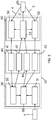
- Fig. 3 shows a logical configuration of the control device 10.
- the control device 10 comprises three logical sections, a configuration section 30, a drive parameter section 40 and a drive function section 50. All three sections are implemented by the units of Fig. 1 .
- a user input 1 is processed to extract tuning criteria 31.
- tuning criteria may define for example the target stabilization time.
- First updated parameters 32 depending on the proportional speed gain are generated based on the tuning criteria 31 and second updated parameters 33 of the load or servo motor 20.
- a load characteristic estimation result 41 (i.e., information about the load being moved by the servo motor 20) is forwarded to the configuration section 30 for generating second updated parameters 33 of the load or servo motor 20.
- the drive parameter section also receives the second updated parameters 33 of the load or servo motor 20 to be able to forward load characteristic parameters 42 to the drive function section 50.
- the drive parameter section 40 receives a tuning measurement 52 from the drive function section 50 and forwards this information 43 for example as stabilization time or overshoot information to the configuration section 30 for generating the first updated parameters 32 depending on the proportional speed gain.
- the first updated parameters 32 are received by the drive parameter section 40 for forwarding current gain parameters 44 to the drive function section 50.
- the drive function section 50 communicates directly with the servo motor 20 and receives a motor speed 4 as well as the feedback value 3 including information of the proportional speed gain and the stabilization time.
- a motor control function 51 receives the current gain parameters 44 as well as the load characteristic parameters 42 and generates a control signal 2 for controlling the servo motor 20.
- the motor control function 51 which can be a physical motor control unit being integrated into the control device 10, generates a command value for initiating a measurement of the tuning parameters 52 as well as a command value for estimating the load characteristics 53. This information is sent to the drive parameter section 40.
- the control device 10 as described with reference to Fig. 1 implements in particular the functions of the logical drive function section 50.
- control device 10 The functions and features of the control device 10 will now be described in greater detail with respect to Figs. 4 and 5 .
- Fig. 4 shows a first example of a method for tuning a servo motor 20.
- the user input 1 can include information about the movement of the servo motor 20 and may also include tuning information like a target stabilization time.
- step S1 an inertia of the servo motor 20 can be estimated. This step is only optional and can also be omitted.
- step S2 measurements of parameters are performed and the next proportional speed gain is determined based on these measurements.
- the calculation unit 11 determines the current proportional speed gain K n of the servo motor 20, determines the current stabilization time ratio and calculates the stabilization time ratio based on the current stabilization time and the target stabilization time.
- step S2 the determination unit 12 selects either the one step gain determination process or the skip step gain determination process based on the calculated stabilization time ratio as described above. The selected gain determination process is then used for determining the next proportional speed gain K n+1 .
- steps S3 and S4 are shown as following step S2, these steps are carried out simultaneously as described above.
- step S5 it will be checked whether the target stabilization time is fulfilled. If there are failures, a failure signal will be output in step S7. This may be the case for example due to measurement failures. In such a case, the method can start again as step S1. It is also possible that the target stabilization time is varied in this case, either automatically or due to renewed user input.
- step S6 If the target stabilization time is not yet reached, the proportional speed gain and the dependent parameters are updated in step S6 and the method continues with the next measurement in step S2.
- step S8 If the target stabilization time is reached, the method will end in step S8 with a success.
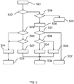
- Fig. 5 shows a second example of a method for tuning a servo motor 20.
- step S21 the method is started.
- step S22 it is decided whether vibrations are detected. This step may be carried out simultaneously to the steps S2 to S6 of Fig. 4 .
- the detection unit 14 confirms whether these vibrations can be eliminated using filters by comparing the current proportional speed gain and the newly determined next proportional speed gain in step S23.
- step S24 If the current proportional speed gain is larger than the newly determined next proportional speed gain, the vibrations are not eliminated and the parameters are restored in step S24, i.e. the previous parameters are used. The method is then aborted in step S25 and the measurements can start again.
- step S26 If the current proportional speed gain is smaller than the newly determined next proportional speed gain, the vibrations are confirmed. Afterwards, it is checked in step S26 if the notch of the servo motor is adopted.
- the detection unit 14 disables the skip step gain determination process in step S27, which means that only the one step gain determination process can be used.
- step S36 the method ends in step S36 and starts again.
- step S28 the detection unit 14 checks whether a damping setting is called in step S28. If a damping setting is called, the servo motor 20 is instructed to reduce damping. If the damping setting is called, the damping setting is carried out in step S29. Afterwards, the method can start again.
- the calculation unit 11 notes, i.e. receives or measures, the current parameters of the servo motor 20 including the stabilization time in step S30.
- step S31 it is checked whether the current stabilization time is less or equal to the target stabilization time.
- step S32 the method ends in step S32 with a success.
- step S33 If this is not fulfilled, it is checked whether the skip step gain determination process is enabled in step S33.
- step S27 If the skip step gain determination process is disabled, for example in step S27, the next proportional speed gain is determined using the one step gain determination process in step S35, which is described above.
- step S34 the next proportional speed gain is determined using the skip step gain determination process in step S34, which is described above.
- step S34 or S35 After determining the next proportional speed gain in step S34 or S35, the parameters are updated, the control signal is generated and the method starts again (S36).
- the described control device 10 provides the possibility to determine the proportional speed gain dependent on the stabilization time ratio so that the servo motor can be controlled based on the stabilization time ratio.
- the stabilization time can be reduced as far as possible while, at the same time, overshoot and resonances of the servo motor 20 can be eliminated or at least reduced.
Landscapes
- Engineering & Computer Science (AREA)
- Physics & Mathematics (AREA)
- Automation & Control Theory (AREA)
- General Physics & Mathematics (AREA)
- Computer Vision & Pattern Recognition (AREA)
- Medical Informatics (AREA)
- Software Systems (AREA)
- Evolutionary Computation (AREA)
- Health & Medical Sciences (AREA)
- Artificial Intelligence (AREA)
- Power Engineering (AREA)
- Control Of Electric Motors In General (AREA)
- Feedback Control In General (AREA)
Applications Claiming Priority (1)
| Application Number | Priority Date | Filing Date | Title |
|---|---|---|---|
| EP16382113.5A EP3220215A1 (fr) | 2016-03-14 | 2016-03-14 | Dispositif de commande et procédé pour accorder un servomoteur |
Publications (4)
| Publication Number | Publication Date |
|---|---|
| EP3220214A2 EP3220214A2 (fr) | 2017-09-20 |
| EP3220214A3 EP3220214A3 (fr) | 2017-10-04 |
| EP3220214A9 true EP3220214A9 (fr) | 2018-01-17 |
| EP3220214B1 EP3220214B1 (fr) | 2018-10-17 |
Family
ID=55755543
Family Applications (2)
| Application Number | Title | Priority Date | Filing Date |
|---|---|---|---|
| EP16382113.5A Withdrawn EP3220215A1 (fr) | 2016-03-14 | 2016-03-14 | Dispositif de commande et procédé pour accorder un servomoteur |
| EP17160348.3A Active EP3220214B1 (fr) | 2016-03-14 | 2017-03-10 | Dispositif de réglage de paramètre de commande et procédé de réglage de paramètre de commande |
Family Applications Before (1)
| Application Number | Title | Priority Date | Filing Date |
|---|---|---|---|
| EP16382113.5A Withdrawn EP3220215A1 (fr) | 2016-03-14 | 2016-03-14 | Dispositif de commande et procédé pour accorder un servomoteur |
Country Status (4)
| Country | Link |
|---|---|
| US (1) | US10416612B2 (fr) |
| EP (2) | EP3220215A1 (fr) |
| JP (1) | JP6409886B2 (fr) |
| CN (1) | CN107196581B (fr) |
Families Citing this family (7)
| Publication number | Priority date | Publication date | Assignee | Title |
|---|---|---|---|---|
| US11615659B2 (en) * | 2018-05-17 | 2023-03-28 | Arcus Technology, Inc. | Motion system health management using multidimensional modeling using motor operational parameters |
| CN109634149B (zh) * | 2018-12-20 | 2021-08-27 | 深圳市英威腾电气股份有限公司 | 一种拉丝机变频器的控制方法、系统、设备及存储介质 |
| CN110515348B (zh) * | 2019-09-19 | 2021-03-23 | 西安交通大学 | 一种机床的伺服电机选型方法 |
| US12153385B2 (en) * | 2021-05-07 | 2024-11-26 | Sony Group Corporation | Methods and systems to adapt PID coefficients through reinforcement learning |
| US12117803B2 (en) | 2022-01-25 | 2024-10-15 | Delta Electronics, Inc. | Servo actuator and fast self-tuning method of gain for using the same |
| CN116545327A (zh) * | 2022-01-25 | 2023-08-04 | 台达电子工业股份有限公司 | 伺服驱动器及其增益快速自调整方法 |
| IT202400003724A1 (it) | 2024-02-21 | 2025-08-21 | Omron Europe B V | Metodo e sistema di selezione automatica della regolazione per la regolazione di servomotori |
Family Cites Families (19)
| Publication number | Priority date | Publication date | Assignee | Title |
|---|---|---|---|---|
| EP0360206A3 (fr) * | 1988-09-21 | 1990-12-19 | Hitachi, Ltd. | Régulateur auto-adaptatif et dispositif de commande de processus |
| JPH04186401A (ja) | 1990-11-21 | 1992-07-03 | Hitachi Ltd | デイジタル制御装置のチユーニング方法及び装置 |
| JPH05173605A (ja) | 1991-05-15 | 1993-07-13 | Toyota Central Res & Dev Lab Inc | 内燃機関の回転速度pid制御器用ゲイン調整装置 |
| DE4215959C2 (de) * | 1991-05-15 | 1997-01-16 | Toyoda Automatic Loom Works | Verstärkungsfaktor-Einstelleinrichtung für PID-Regler |
| JPH06242803A (ja) | 1993-02-16 | 1994-09-02 | Matsushita Electric Ind Co Ltd | 自動調整サーボ制御装置 |
| JP2950149B2 (ja) * | 1994-05-30 | 1999-09-20 | 株式会社デンソー | オートチューニングコントローラ |
| US5610489A (en) * | 1994-08-26 | 1997-03-11 | Trinova Corporation | Method and apparatus for machine control |
| US5684374A (en) * | 1995-07-27 | 1997-11-04 | Allen-Bradley Company, Inc. | Method and apparatus for tuning a motion control system having an external velocity loop |
| DE10211391A1 (de) * | 2002-03-15 | 2003-10-02 | Braun Gmbh | Elektrische Zahnbürste und Zahnbürstenkopf hierfür |
| JPWO2004008624A1 (ja) * | 2002-07-11 | 2005-11-17 | 株式会社安川電機 | サーボ制御装置のゲイン調整方法 |
| JP2006302297A (ja) | 2003-10-22 | 2006-11-02 | Omron Corp | 制御システム設定装置および制御システム設定方法ならびに設定プログラム |
| US7198875B2 (en) * | 2004-06-25 | 2007-04-03 | Xerox Corporation | Amino-functional siloxane copolymer release agents for fuser members |
| JP4842541B2 (ja) | 2005-01-07 | 2011-12-21 | 株式会社デジタル | 制御用表示装置、画面データ生成装置、並びに、それらのプログラムおよび記録媒体 |
| US7328138B1 (en) * | 2005-07-21 | 2008-02-05 | Storage Technology Corporation | Method and system of measurement and optimization of noise in servo systems |
| JP2008259271A (ja) | 2007-04-02 | 2008-10-23 | Yaskawa Electric Corp | サーボ制御装置と定数自動調整方法 |
| US8232758B2 (en) * | 2009-08-28 | 2012-07-31 | Fanuc Ltd | Controller of electric motor having function of estimating inertia and friction simultaneously |
| JP6118988B2 (ja) | 2013-04-09 | 2017-04-26 | パナソニックIpマネジメント株式会社 | モータ駆動装置 |
| DE112013007444B4 (de) * | 2013-10-11 | 2020-03-05 | Mitsubishi Electric Corporation | Einstell- und Justierfunktionsunterstützungseinrichtung für ein Mehrachsen-Steuerungssystem |
| EP3076260B1 (fr) * | 2013-11-26 | 2021-03-24 | FUJI Corporation | Dispositif et procédé d'assistance dans un travail de conception d'amélioration pour un dispositif mécanique |
-
2016
- 2016-03-14 EP EP16382113.5A patent/EP3220215A1/fr not_active Withdrawn
-
2017
- 2017-01-20 US US15/410,779 patent/US10416612B2/en active Active
- 2017-01-20 CN CN201710045351.8A patent/CN107196581B/zh active Active
- 2017-01-23 JP JP2017009075A patent/JP6409886B2/ja active Active
- 2017-03-10 EP EP17160348.3A patent/EP3220214B1/fr active Active
Also Published As
| Publication number | Publication date |
|---|---|
| EP3220215A1 (fr) | 2017-09-20 |
| CN107196581B (zh) | 2020-01-07 |
| JP6409886B2 (ja) | 2018-10-24 |
| US20170261946A1 (en) | 2017-09-14 |
| CN107196581A (zh) | 2017-09-22 |
| EP3220214A2 (fr) | 2017-09-20 |
| EP3220214A3 (fr) | 2017-10-04 |
| JP2017169437A (ja) | 2017-09-21 |
| EP3220214B1 (fr) | 2018-10-17 |
| US10416612B2 (en) | 2019-09-17 |
Similar Documents
| Publication | Publication Date | Title |
|---|---|---|
| EP3220214B1 (fr) | Dispositif de réglage de paramètre de commande et procédé de réglage de paramètre de commande | |
| US9423786B2 (en) | Motor drive device | |
| US20160202688A1 (en) | Automatic parameter adjustment device for adjusting parameter corresponding to processing condition | |
| US20200150599A1 (en) | Output device, control device, and method for outputting evaluation functions and machine learning results | |
| US20170032282A1 (en) | Machine learning apparatus for learning gain optimization, motor control apparatus equipped with machine learning apparatus, and machine learning method | |
| US10310489B2 (en) | Servo controller | |
| KR20150139519A (ko) | 모터 구동 장치 | |
| JP2003061377A (ja) | オートチューニング機能を備えたモータ制御装置 | |
| US20230176532A1 (en) | Control assist device, control device, and control assist method | |
| US10317884B2 (en) | Servo controller | |
| CN112470396B (zh) | 设定支持装置 | |
| US11086277B2 (en) | System and method for determining the parameters of a controller | |
| JP6646025B2 (ja) | 制御装置及び機械学習装置 | |
| KR102451225B1 (ko) | 제어 장치의 조정 지원 장치 및 제어 장치의 조정 장치 | |
| JP2007306753A (ja) | ノッチフィルタのパラメータ調整方法、プログラムおよびモータ制御装置 | |
| US20240027972A1 (en) | Work control method, work control system, and work control apparatus of construction machine | |
| JP2641855B2 (ja) | 適応制御装置 | |
| JP4752298B2 (ja) | モータ制御装置およびその制御方法 | |
| CN112425065B (zh) | 设定支持装置 | |
| JP4546437B2 (ja) | オートチューニング装置およびオートチューニング方法 | |
| JP7699504B2 (ja) | サーボアンプのオートチューニング方法及びモータ制御装置 | |
| JP7482201B1 (ja) | モータ制御システム、制御パラメータ自動調整方法、及び、自動調整プログラム | |
| JP4025971B2 (ja) | 電動機制御装置およびそのゲイン設定方法 | |
| JP4200357B2 (ja) | 電動機制御装置の運転立上げ方法および電動機制御装置 | |
| JP7558456B1 (ja) | モータ制御装置およびモータ制御方法 |
Legal Events
| Date | Code | Title | Description |
|---|---|---|---|
| PUAI | Public reference made under article 153(3) epc to a published international application that has entered the european phase |
Free format text: ORIGINAL CODE: 0009012 |
|
| STAA | Information on the status of an ep patent application or granted ep patent |
Free format text: STATUS: THE APPLICATION HAS BEEN PUBLISHED |
|
| PUAL | Search report despatched |
Free format text: ORIGINAL CODE: 0009013 |
|
| AK | Designated contracting states |
Kind code of ref document: A2 Designated state(s): AL AT BE BG CH CY CZ DE DK EE ES FI FR GB GR HR HU IE IS IT LI LT LU LV MC MK MT NL NO PL PT RO RS SE SI SK SM TR |
|
| AX | Request for extension of the european patent |
Extension state: BA ME |
|
| AK | Designated contracting states |
Kind code of ref document: A3 Designated state(s): AL AT BE BG CH CY CZ DE DK EE ES FI FR GB GR HR HU IE IS IT LI LT LU LV MC MK MT NL NO PL PT RO RS SE SI SK SM TR |
|
| AX | Request for extension of the european patent |
Extension state: BA ME |
|
| RIC1 | Information provided on ipc code assigned before grant |
Ipc: G05B 11/42 20060101AFI20170828BHEP Ipc: G05B 13/02 20060101ALN20170828BHEP |
|
| STAA | Information on the status of an ep patent application or granted ep patent |
Free format text: STATUS: REQUEST FOR EXAMINATION WAS MADE |
|
| 17P | Request for examination filed |
Effective date: 20180322 |
|
| RBV | Designated contracting states (corrected) |
Designated state(s): AL AT BE BG CH CY CZ DE DK EE ES FI FR GB GR HR HU IE IS IT LI LT LU LV MC MK MT NL NO PL PT RO RS SE SI SK SM TR |
|
| GRAP | Despatch of communication of intention to grant a patent |
Free format text: ORIGINAL CODE: EPIDOSNIGR1 |
|
| STAA | Information on the status of an ep patent application or granted ep patent |
Free format text: STATUS: GRANT OF PATENT IS INTENDED |
|
| RIC1 | Information provided on ipc code assigned before grant |
Ipc: G05B 11/42 20060101AFI20180413BHEP Ipc: G05B 13/02 20060101ALN20180413BHEP |
|
| INTG | Intention to grant announced |
Effective date: 20180516 |
|
| RAP1 | Party data changed (applicant data changed or rights of an application transferred) |
Owner name: OMRON CORPORATION |
|
| GRAS | Grant fee paid |
Free format text: ORIGINAL CODE: EPIDOSNIGR3 |
|
| GRAA | (expected) grant |
Free format text: ORIGINAL CODE: 0009210 |
|
| STAA | Information on the status of an ep patent application or granted ep patent |
Free format text: STATUS: THE PATENT HAS BEEN GRANTED |
|
| AK | Designated contracting states |
Kind code of ref document: B1 Designated state(s): AL AT BE BG CH CY CZ DE DK EE ES FI FR GB GR HR HU IE IS IT LI LT LU LV MC MK MT NL NO PL PT RO RS SE SI SK SM TR |
|
| REG | Reference to a national code |
Ref country code: GB Ref legal event code: FG4D |
|
| REG | Reference to a national code |
Ref country code: CH Ref legal event code: EP |
|
| REG | Reference to a national code |
Ref country code: IE Ref legal event code: FG4D |
|
| REG | Reference to a national code |
Ref country code: DE Ref legal event code: R096 Ref document number: 602017000617 Country of ref document: DE Ref country code: AT Ref legal event code: REF Ref document number: 1054736 Country of ref document: AT Kind code of ref document: T Effective date: 20181115 |
|
| REG | Reference to a national code |
Ref country code: NL Ref legal event code: MP Effective date: 20181017 |
|
| REG | Reference to a national code |
Ref country code: LT Ref legal event code: MG4D |
|
| REG | Reference to a national code |
Ref country code: AT Ref legal event code: MK05 Ref document number: 1054736 Country of ref document: AT Kind code of ref document: T Effective date: 20181017 |
|
| PG25 | Lapsed in a contracting state [announced via postgrant information from national office to epo] |
Ref country code: NL Free format text: LAPSE BECAUSE OF FAILURE TO SUBMIT A TRANSLATION OF THE DESCRIPTION OR TO PAY THE FEE WITHIN THE PRESCRIBED TIME-LIMIT Effective date: 20181017 |
|
| PG25 | Lapsed in a contracting state [announced via postgrant information from national office to epo] |
Ref country code: FI Free format text: LAPSE BECAUSE OF FAILURE TO SUBMIT A TRANSLATION OF THE DESCRIPTION OR TO PAY THE FEE WITHIN THE PRESCRIBED TIME-LIMIT Effective date: 20181017 Ref country code: BG Free format text: LAPSE BECAUSE OF FAILURE TO SUBMIT A TRANSLATION OF THE DESCRIPTION OR TO PAY THE FEE WITHIN THE PRESCRIBED TIME-LIMIT Effective date: 20190117 Ref country code: PL Free format text: LAPSE BECAUSE OF FAILURE TO SUBMIT A TRANSLATION OF THE DESCRIPTION OR TO PAY THE FEE WITHIN THE PRESCRIBED TIME-LIMIT Effective date: 20181017 Ref country code: AT Free format text: LAPSE BECAUSE OF FAILURE TO SUBMIT A TRANSLATION OF THE DESCRIPTION OR TO PAY THE FEE WITHIN THE PRESCRIBED TIME-LIMIT Effective date: 20181017 Ref country code: LT Free format text: LAPSE BECAUSE OF FAILURE TO SUBMIT A TRANSLATION OF THE DESCRIPTION OR TO PAY THE FEE WITHIN THE PRESCRIBED TIME-LIMIT Effective date: 20181017 Ref country code: NO Free format text: LAPSE BECAUSE OF FAILURE TO SUBMIT A TRANSLATION OF THE DESCRIPTION OR TO PAY THE FEE WITHIN THE PRESCRIBED TIME-LIMIT Effective date: 20190117 Ref country code: IS Free format text: LAPSE BECAUSE OF FAILURE TO SUBMIT A TRANSLATION OF THE DESCRIPTION OR TO PAY THE FEE WITHIN THE PRESCRIBED TIME-LIMIT Effective date: 20190217 Ref country code: ES Free format text: LAPSE BECAUSE OF FAILURE TO SUBMIT A TRANSLATION OF THE DESCRIPTION OR TO PAY THE FEE WITHIN THE PRESCRIBED TIME-LIMIT Effective date: 20181017 Ref country code: HR Free format text: LAPSE BECAUSE OF FAILURE TO SUBMIT A TRANSLATION OF THE DESCRIPTION OR TO PAY THE FEE WITHIN THE PRESCRIBED TIME-LIMIT Effective date: 20181017 Ref country code: LV Free format text: LAPSE BECAUSE OF FAILURE TO SUBMIT A TRANSLATION OF THE DESCRIPTION OR TO PAY THE FEE WITHIN THE PRESCRIBED TIME-LIMIT Effective date: 20181017 |
|
| PG25 | Lapsed in a contracting state [announced via postgrant information from national office to epo] |
Ref country code: AL Free format text: LAPSE BECAUSE OF FAILURE TO SUBMIT A TRANSLATION OF THE DESCRIPTION OR TO PAY THE FEE WITHIN THE PRESCRIBED TIME-LIMIT Effective date: 20181017 Ref country code: SE Free format text: LAPSE BECAUSE OF FAILURE TO SUBMIT A TRANSLATION OF THE DESCRIPTION OR TO PAY THE FEE WITHIN THE PRESCRIBED TIME-LIMIT Effective date: 20181017 Ref country code: RS Free format text: LAPSE BECAUSE OF FAILURE TO SUBMIT A TRANSLATION OF THE DESCRIPTION OR TO PAY THE FEE WITHIN THE PRESCRIBED TIME-LIMIT Effective date: 20181017 Ref country code: GR Free format text: LAPSE BECAUSE OF FAILURE TO SUBMIT A TRANSLATION OF THE DESCRIPTION OR TO PAY THE FEE WITHIN THE PRESCRIBED TIME-LIMIT Effective date: 20190118 Ref country code: PT Free format text: LAPSE BECAUSE OF FAILURE TO SUBMIT A TRANSLATION OF THE DESCRIPTION OR TO PAY THE FEE WITHIN THE PRESCRIBED TIME-LIMIT Effective date: 20190217 |
|
| REG | Reference to a national code |
Ref country code: DE Ref legal event code: R097 Ref document number: 602017000617 Country of ref document: DE |
|
| PG25 | Lapsed in a contracting state [announced via postgrant information from national office to epo] |
Ref country code: IT Free format text: LAPSE BECAUSE OF FAILURE TO SUBMIT A TRANSLATION OF THE DESCRIPTION OR TO PAY THE FEE WITHIN THE PRESCRIBED TIME-LIMIT Effective date: 20181017 Ref country code: DK Free format text: LAPSE BECAUSE OF FAILURE TO SUBMIT A TRANSLATION OF THE DESCRIPTION OR TO PAY THE FEE WITHIN THE PRESCRIBED TIME-LIMIT Effective date: 20181017 Ref country code: CZ Free format text: LAPSE BECAUSE OF FAILURE TO SUBMIT A TRANSLATION OF THE DESCRIPTION OR TO PAY THE FEE WITHIN THE PRESCRIBED TIME-LIMIT Effective date: 20181017 |
|
| PLBE | No opposition filed within time limit |
Free format text: ORIGINAL CODE: 0009261 |
|
| STAA | Information on the status of an ep patent application or granted ep patent |
Free format text: STATUS: NO OPPOSITION FILED WITHIN TIME LIMIT |
|
| PG25 | Lapsed in a contracting state [announced via postgrant information from national office to epo] |
Ref country code: EE Free format text: LAPSE BECAUSE OF FAILURE TO SUBMIT A TRANSLATION OF THE DESCRIPTION OR TO PAY THE FEE WITHIN THE PRESCRIBED TIME-LIMIT Effective date: 20181017 Ref country code: RO Free format text: LAPSE BECAUSE OF FAILURE TO SUBMIT A TRANSLATION OF THE DESCRIPTION OR TO PAY THE FEE WITHIN THE PRESCRIBED TIME-LIMIT Effective date: 20181017 Ref country code: SK Free format text: LAPSE BECAUSE OF FAILURE TO SUBMIT A TRANSLATION OF THE DESCRIPTION OR TO PAY THE FEE WITHIN THE PRESCRIBED TIME-LIMIT Effective date: 20181017 Ref country code: SM Free format text: LAPSE BECAUSE OF FAILURE TO SUBMIT A TRANSLATION OF THE DESCRIPTION OR TO PAY THE FEE WITHIN THE PRESCRIBED TIME-LIMIT Effective date: 20181017 |
|
| 26N | No opposition filed |
Effective date: 20190718 |
|
| PG25 | Lapsed in a contracting state [announced via postgrant information from national office to epo] |
Ref country code: SI Free format text: LAPSE BECAUSE OF FAILURE TO SUBMIT A TRANSLATION OF THE DESCRIPTION OR TO PAY THE FEE WITHIN THE PRESCRIBED TIME-LIMIT Effective date: 20181017 Ref country code: MC Free format text: LAPSE BECAUSE OF FAILURE TO SUBMIT A TRANSLATION OF THE DESCRIPTION OR TO PAY THE FEE WITHIN THE PRESCRIBED TIME-LIMIT Effective date: 20181017 |
|
| PG25 | Lapsed in a contracting state [announced via postgrant information from national office to epo] |
Ref country code: LU Free format text: LAPSE BECAUSE OF NON-PAYMENT OF DUE FEES Effective date: 20190310 |
|
| REG | Reference to a national code |
Ref country code: BE Ref legal event code: MM Effective date: 20190331 |
|
| PG25 | Lapsed in a contracting state [announced via postgrant information from national office to epo] |
Ref country code: IE Free format text: LAPSE BECAUSE OF NON-PAYMENT OF DUE FEES Effective date: 20190310 |
|
| PG25 | Lapsed in a contracting state [announced via postgrant information from national office to epo] |
Ref country code: FR Free format text: LAPSE BECAUSE OF NON-PAYMENT OF DUE FEES Effective date: 20190331 Ref country code: BE Free format text: LAPSE BECAUSE OF NON-PAYMENT OF DUE FEES Effective date: 20190331 |
|
| PG25 | Lapsed in a contracting state [announced via postgrant information from national office to epo] |
Ref country code: TR Free format text: LAPSE BECAUSE OF FAILURE TO SUBMIT A TRANSLATION OF THE DESCRIPTION OR TO PAY THE FEE WITHIN THE PRESCRIBED TIME-LIMIT Effective date: 20181017 |
|
| PG25 | Lapsed in a contracting state [announced via postgrant information from national office to epo] |
Ref country code: MT Free format text: LAPSE BECAUSE OF NON-PAYMENT OF DUE FEES Effective date: 20190310 |
|
| REG | Reference to a national code |
Ref country code: CH Ref legal event code: PL |
|
| PG25 | Lapsed in a contracting state [announced via postgrant information from national office to epo] |
Ref country code: CH Free format text: LAPSE BECAUSE OF NON-PAYMENT OF DUE FEES Effective date: 20200331 Ref country code: LI Free format text: LAPSE BECAUSE OF NON-PAYMENT OF DUE FEES Effective date: 20200331 |
|
| PG25 | Lapsed in a contracting state [announced via postgrant information from national office to epo] |
Ref country code: CY Free format text: LAPSE BECAUSE OF FAILURE TO SUBMIT A TRANSLATION OF THE DESCRIPTION OR TO PAY THE FEE WITHIN THE PRESCRIBED TIME-LIMIT Effective date: 20181017 |
|
| PG25 | Lapsed in a contracting state [announced via postgrant information from national office to epo] |
Ref country code: HU Free format text: LAPSE BECAUSE OF FAILURE TO SUBMIT A TRANSLATION OF THE DESCRIPTION OR TO PAY THE FEE WITHIN THE PRESCRIBED TIME-LIMIT; INVALID AB INITIO Effective date: 20170310 |
|
| GBPC | Gb: european patent ceased through non-payment of renewal fee |
Effective date: 20210310 |
|
| PG25 | Lapsed in a contracting state [announced via postgrant information from national office to epo] |
Ref country code: GB Free format text: LAPSE BECAUSE OF NON-PAYMENT OF DUE FEES Effective date: 20210310 |
|
| PG25 | Lapsed in a contracting state [announced via postgrant information from national office to epo] |
Ref country code: MK Free format text: LAPSE BECAUSE OF FAILURE TO SUBMIT A TRANSLATION OF THE DESCRIPTION OR TO PAY THE FEE WITHIN THE PRESCRIBED TIME-LIMIT Effective date: 20181017 |
|
| PGFP | Annual fee paid to national office [announced via postgrant information from national office to epo] |
Ref country code: DE Payment date: 20260320 Year of fee payment: 10 |