EP3220465B1 - Procédé de fabrication d'élément à circuit d'écoulement pour pile à combustible - Google Patents
Procédé de fabrication d'élément à circuit d'écoulement pour pile à combustible Download PDFInfo
- Publication number
- EP3220465B1 EP3220465B1 EP15859373.1A EP15859373A EP3220465B1 EP 3220465 B1 EP3220465 B1 EP 3220465B1 EP 15859373 A EP15859373 A EP 15859373A EP 3220465 B1 EP3220465 B1 EP 3220465B1
- Authority
- EP
- European Patent Office
- Prior art keywords
- resin
- base part
- conductor part
- grooved base
- grooved
- Prior art date
- Legal status (The legal status is an assumption and is not a legal conclusion. Google has not performed a legal analysis and makes no representation as to the accuracy of the status listed.)
- Active
Links
Images





Classifications
-
- H—ELECTRICITY
- H01—ELECTRIC ELEMENTS
- H01M—PROCESSES OR MEANS, e.g. BATTERIES, FOR THE DIRECT CONVERSION OF CHEMICAL ENERGY INTO ELECTRICAL ENERGY
- H01M8/00—Fuel cells; Manufacture thereof
- H01M8/02—Details
- H01M8/0202—Collectors; Separators, e.g. bipolar separators; Interconnectors
- H01M8/0204—Non-porous and characterised by the material
- H01M8/0223—Composites
- H01M8/0228—Composites in the form of layered or coated products
-
- H—ELECTRICITY
- H01—ELECTRIC ELEMENTS
- H01B—CABLES; CONDUCTORS; INSULATORS; SELECTION OF MATERIALS FOR THEIR CONDUCTIVE, INSULATING OR DIELECTRIC PROPERTIES
- H01B1/00—Conductors or conductive bodies characterised by the conductive materials; Selection of materials as conductors
- H01B1/06—Conductors or conductive bodies characterised by the conductive materials; Selection of materials as conductors mainly consisting of other non-metallic substances
- H01B1/12—Conductors or conductive bodies characterised by the conductive materials; Selection of materials as conductors mainly consisting of other non-metallic substances organic substances
- H01B1/124—Intrinsically conductive polymers
-
- H—ELECTRICITY
- H01—ELECTRIC ELEMENTS
- H01M—PROCESSES OR MEANS, e.g. BATTERIES, FOR THE DIRECT CONVERSION OF CHEMICAL ENERGY INTO ELECTRICAL ENERGY
- H01M8/00—Fuel cells; Manufacture thereof
- H01M8/10—Fuel cells with solid electrolytes
- H01M8/1016—Fuel cells with solid electrolytes characterised by the electrolyte material
- H01M8/1018—Polymeric electrolyte materials
- H01M8/1041—Polymer electrolyte composites, mixtures or blends
- H01M8/1055—Inorganic layers on the polymer electrolytes, e.g. inorganic coatings
-
- H—ELECTRICITY
- H01—ELECTRIC ELEMENTS
- H01M—PROCESSES OR MEANS, e.g. BATTERIES, FOR THE DIRECT CONVERSION OF CHEMICAL ENERGY INTO ELECTRICAL ENERGY
- H01M8/00—Fuel cells; Manufacture thereof
- H01M8/02—Details
- H01M8/0202—Collectors; Separators, e.g. bipolar separators; Interconnectors
- H01M8/0204—Non-porous and characterised by the material
- H01M8/0206—Metals or alloys
-
- H—ELECTRICITY
- H01—ELECTRIC ELEMENTS
- H01M—PROCESSES OR MEANS, e.g. BATTERIES, FOR THE DIRECT CONVERSION OF CHEMICAL ENERGY INTO ELECTRICAL ENERGY
- H01M8/00—Fuel cells; Manufacture thereof
- H01M8/02—Details
- H01M8/0202—Collectors; Separators, e.g. bipolar separators; Interconnectors
- H01M8/0204—Non-porous and characterised by the material
- H01M8/0213—Gas-impermeable carbon-containing materials
-
- H—ELECTRICITY
- H01—ELECTRIC ELEMENTS
- H01M—PROCESSES OR MEANS, e.g. BATTERIES, FOR THE DIRECT CONVERSION OF CHEMICAL ENERGY INTO ELECTRICAL ENERGY
- H01M8/00—Fuel cells; Manufacture thereof
- H01M8/02—Details
- H01M8/0202—Collectors; Separators, e.g. bipolar separators; Interconnectors
- H01M8/0204—Non-porous and characterised by the material
- H01M8/0221—Organic resins; Organic polymers
-
- H—ELECTRICITY
- H01—ELECTRIC ELEMENTS
- H01M—PROCESSES OR MEANS, e.g. BATTERIES, FOR THE DIRECT CONVERSION OF CHEMICAL ENERGY INTO ELECTRICAL ENERGY
- H01M8/00—Fuel cells; Manufacture thereof
- H01M8/02—Details
- H01M8/0202—Collectors; Separators, e.g. bipolar separators; Interconnectors
- H01M8/0258—Collectors; Separators, e.g. bipolar separators; Interconnectors characterised by the configuration of channels, e.g. by the flow field of the reactant or coolant
-
- H—ELECTRICITY
- H01—ELECTRIC ELEMENTS
- H01M—PROCESSES OR MEANS, e.g. BATTERIES, FOR THE DIRECT CONVERSION OF CHEMICAL ENERGY INTO ELECTRICAL ENERGY
- H01M8/00—Fuel cells; Manufacture thereof
- H01M8/02—Details
- H01M8/0202—Collectors; Separators, e.g. bipolar separators; Interconnectors
- H01M8/0258—Collectors; Separators, e.g. bipolar separators; Interconnectors characterised by the configuration of channels, e.g. by the flow field of the reactant or coolant
- H01M8/026—Collectors; Separators, e.g. bipolar separators; Interconnectors characterised by the configuration of channels, e.g. by the flow field of the reactant or coolant characterised by grooves, e.g. their pitch or depth
-
- H—ELECTRICITY
- H01—ELECTRIC ELEMENTS
- H01M—PROCESSES OR MEANS, e.g. BATTERIES, FOR THE DIRECT CONVERSION OF CHEMICAL ENERGY INTO ELECTRICAL ENERGY
- H01M8/00—Fuel cells; Manufacture thereof
- H01M8/10—Fuel cells with solid electrolytes
- H01M8/1016—Fuel cells with solid electrolytes characterised by the electrolyte material
- H01M8/1018—Polymeric electrolyte materials
- H01M8/102—Polymeric electrolyte materials characterised by the chemical structure of the main chain of the ion-conducting polymer
- H01M8/1027—Polymeric electrolyte materials characterised by the chemical structure of the main chain of the ion-conducting polymer having carbon, oxygen and other atoms, e.g. sulfonated polyethersulfones [S-PES]
-
- H—ELECTRICITY
- H01—ELECTRIC ELEMENTS
- H01M—PROCESSES OR MEANS, e.g. BATTERIES, FOR THE DIRECT CONVERSION OF CHEMICAL ENERGY INTO ELECTRICAL ENERGY
- H01M8/00—Fuel cells; Manufacture thereof
- H01M8/10—Fuel cells with solid electrolytes
- H01M8/1016—Fuel cells with solid electrolytes characterised by the electrolyte material
- H01M8/1018—Polymeric electrolyte materials
- H01M8/1041—Polymer electrolyte composites, mixtures or blends
- H01M8/1053—Polymer electrolyte composites, mixtures or blends consisting of layers of polymers with at least one layer being ionically conductive
-
- H—ELECTRICITY
- H01—ELECTRIC ELEMENTS
- H01M—PROCESSES OR MEANS, e.g. BATTERIES, FOR THE DIRECT CONVERSION OF CHEMICAL ENERGY INTO ELECTRICAL ENERGY
- H01M8/00—Fuel cells; Manufacture thereof
- H01M8/10—Fuel cells with solid electrolytes
- H01M8/1016—Fuel cells with solid electrolytes characterised by the electrolyte material
- H01M8/1018—Polymeric electrolyte materials
- H01M8/1069—Polymeric electrolyte materials characterised by the manufacturing processes
- H01M8/1072—Polymeric electrolyte materials characterised by the manufacturing processes by chemical reactions, e.g. in situ polymerisation or in situ crosslinking
-
- B—PERFORMING OPERATIONS; TRANSPORTING
- B01—PHYSICAL OR CHEMICAL PROCESSES OR APPARATUS IN GENERAL
- B01D—SEPARATION
- B01D71/00—Semi-permeable membranes for separation processes or apparatus characterised by the material; Manufacturing processes specially adapted therefor
- B01D71/06—Organic material
- B01D71/58—Other polymers having nitrogen in the main chain, with or without oxygen or carbon only
-
- B—PERFORMING OPERATIONS; TRANSPORTING
- B01—PHYSICAL OR CHEMICAL PROCESSES OR APPARATUS IN GENERAL
- B01D—SEPARATION
- B01D71/00—Semi-permeable membranes for separation processes or apparatus characterised by the material; Manufacturing processes specially adapted therefor
- B01D71/06—Organic material
- B01D71/76—Macromolecular material not specifically provided for in a single one of groups B01D71/08 - B01D71/74
- B01D71/82—Macromolecular material not specifically provided for in a single one of groups B01D71/08 - B01D71/74 characterised by the presence of specified groups, e.g. introduced by chemical after-treatment
-
- C—CHEMISTRY; METALLURGY
- C08—ORGANIC MACROMOLECULAR COMPOUNDS; THEIR PREPARATION OR CHEMICAL WORKING-UP; COMPOSITIONS BASED THEREON
- C08J—WORKING-UP; GENERAL PROCESSES OF COMPOUNDING; AFTER-TREATMENT NOT COVERED BY SUBCLASSES C08B, C08C, C08F, C08G or C08H
- C08J5/00—Manufacture of articles or shaped materials containing macromolecular substances
- C08J5/20—Manufacture of shaped structures of ion-exchange resins
- C08J5/22—Films, membranes or diaphragms
- C08J5/2206—Films, membranes or diaphragms based on organic and/or inorganic macromolecular compounds
- C08J5/2218—Synthetic macromolecular compounds
- C08J5/2256—Synthetic macromolecular compounds based on macromolecular compounds obtained by reactions other than those involving carbon-to-carbon bonds, e.g. obtained by polycondensation
-
- H—ELECTRICITY
- H01—ELECTRIC ELEMENTS
- H01M—PROCESSES OR MEANS, e.g. BATTERIES, FOR THE DIRECT CONVERSION OF CHEMICAL ENERGY INTO ELECTRICAL ENERGY
- H01M8/00—Fuel cells; Manufacture thereof
- H01M8/10—Fuel cells with solid electrolytes
- H01M2008/1095—Fuel cells with polymeric electrolytes
-
- H—ELECTRICITY
- H01—ELECTRIC ELEMENTS
- H01M—PROCESSES OR MEANS, e.g. BATTERIES, FOR THE DIRECT CONVERSION OF CHEMICAL ENERGY INTO ELECTRICAL ENERGY
- H01M2300/00—Electrolytes
- H01M2300/0017—Non-aqueous electrolytes
- H01M2300/0065—Solid electrolytes
- H01M2300/0082—Organic polymers
-
- H—ELECTRICITY
- H01—ELECTRIC ELEMENTS
- H01M—PROCESSES OR MEANS, e.g. BATTERIES, FOR THE DIRECT CONVERSION OF CHEMICAL ENERGY INTO ELECTRICAL ENERGY
- H01M2300/00—Electrolytes
- H01M2300/0088—Composites
- H01M2300/0091—Composites in the form of mixtures
-
- Y—GENERAL TAGGING OF NEW TECHNOLOGICAL DEVELOPMENTS; GENERAL TAGGING OF CROSS-SECTIONAL TECHNOLOGIES SPANNING OVER SEVERAL SECTIONS OF THE IPC; TECHNICAL SUBJECTS COVERED BY FORMER USPC CROSS-REFERENCE ART COLLECTIONS [XRACs] AND DIGESTS
- Y02—TECHNOLOGIES OR APPLICATIONS FOR MITIGATION OR ADAPTATION AGAINST CLIMATE CHANGE
- Y02E—REDUCTION OF GREENHOUSE GAS [GHG] EMISSIONS, RELATED TO ENERGY GENERATION, TRANSMISSION OR DISTRIBUTION
- Y02E60/00—Enabling technologies; Technologies with a potential or indirect contribution to GHG emissions mitigation
- Y02E60/30—Hydrogen technology
- Y02E60/50—Fuel cells
-
- Y—GENERAL TAGGING OF NEW TECHNOLOGICAL DEVELOPMENTS; GENERAL TAGGING OF CROSS-SECTIONAL TECHNOLOGIES SPANNING OVER SEVERAL SECTIONS OF THE IPC; TECHNICAL SUBJECTS COVERED BY FORMER USPC CROSS-REFERENCE ART COLLECTIONS [XRACs] AND DIGESTS
- Y02—TECHNOLOGIES OR APPLICATIONS FOR MITIGATION OR ADAPTATION AGAINST CLIMATE CHANGE
- Y02P—CLIMATE CHANGE MITIGATION TECHNOLOGIES IN THE PRODUCTION OR PROCESSING OF GOODS
- Y02P70/00—Climate change mitigation technologies in the production process for final industrial or consumer products
- Y02P70/50—Manufacturing or production processes characterised by the final manufactured product
Definitions
- the present invention relates to a method of production of a channel member for fuel cell use, more particularly relates to a method of production for forming a channel member provided with good workability of a resin and good conductivity.
- a fuel cell is a power generating device using a chemical reaction between stored hydrogen or hydrogen obtained by reforming alcohol or ether etc. and the oxygen in the air to obtain electric power.
- typical fuel cells there are phosphoric acid fuel cells (PAFC), molten carbonate fuel cells (MCFC), solid oxide fuel cells (SOFC), and polymer electrolyte fuel cells (PEFC).
- PAFC phosphoric acid fuel cells
- MCFC molten carbonate fuel cells
- SOFC solid oxide fuel cells
- PEFC polymer electrolyte fuel cells
- polymer electrolyte fuel cells are more suitable for reduction of size compared with the other types. For this reason, polymer electrode fuel cells are perfect for mounting in passenger cars and other transport machinery where there are many restrictions on the installation location.
- separators are arranged at both of the fuel electrode supplying the hydrogen (negative electrode/anode) and the air electrode supplying the oxygen (positive electrode/cathode).
- a membrane electrode assembly (MEA) is sandwiched between the two separators.
- This membrane electrode assembly is comprised of a proton conducting membrane at the two sides of which catalyst layers, water repelling layers, and at the outside of the same gas diffusion layers are stacked. Further, the necessary number of combinations of these are connected to form a fuel cell (for example, see PLTs 1 and 2).
- the channels are made finer to increase the surface area of the channels. Further, by forming finer channels, it becomes possible to assemble them inside the membrane electrode assembly or other cell. This being so, it is possible to more efficiently cool the locations where heat is generated inside the cells.
- the present invention was made in consideration of the above situation and provides a method of preparing a channel member for fuel cell use which secures conductivity, is highly convenient for combination with a separator or membrane electrode assembly of a polymer electrolyte fuel cell, enables formation of finer channels, is suitable for the circulation of hydrogen, oxygen, a cooling medium, or other various fluids, is inexpensive and easy to produce, and is low in penetration resistance.
- the invention provides a method of production of a channel member for fuel cell use as specified in any one of independent claims 1 to 4.
- the dependent claim 5 relates to further developments of the invention.
- the channel member for fuel cell use produced according to the present invention is mainly a member to be assembled into a polymer electrolyte fuel cell (PEFC). Therefore, it is a channel for supply of hydrogen and oxygen for generating electric power by an electrochemical reaction and further for the supply of water or another cooling medium for controlling the temperature of the fuel cell.
- PEFC polymer electrolyte fuel cell
- the features of the channel member are the use of a relatively simple structure and inexpensive cost and further the provision of electrical conductivity. First, the structure of the conductor parts and next the production process will be explained.
- FIG. 1 is a partially enlarged cross-sectional schematic view showing in brief a later explained first conductor part and other conductor parts for a channel member for fuel cell use.
- carbon nanotubes 2 are dispersed as a carbon material.
- granular graphite 3 sinum graphite
- carbon fibers 4 are added as still another carbon material.
- FIG. 1(a) inside the resin 1 (later explained first resin etc.), carbon nanotubes 2 are dispersed as a carbon material.
- granular graphite 3 spherical graphite
- carbon fibers 4 are added as still another carbon material.
- FIG. 1 is a partially enlarged cross-sectional schematic view showing in brief a later explained first conductor part and other conductor parts for a channel member for fuel cell use.
- FIG. 1(a) inside the resin 1 (later explained first resin etc.), carbon nanotubes 2 are dispersed as a carbon material. Simultaneously, inside the resin, carbon fibers 4 are added as still another carbon material
- (c) shows the case where all of the three types of carbon materials of the carbon nanotubes 2, granular graphite 3, and carbon fibers 4 are added inside of the resin 1. Despite the conductor parts being formed from a resin material, conductivity can be acquired due to the carbon material.
- the carbon nanotubes 2 are made of a carbon compound comprised of carbon atoms of a diameter of 10 nm to 150 nm or so.
- the weight ratio of the carbon nanotubes in the total weight of the conductor parts is 15 to 30 wt%. If the amount of the carbon nanotubes is made extremely great, the viscosity of the resin rises and easily becomes a cause of shaping defects. Therefore, the above range is preferable.
- the carbon nanotubes themselves have conductivity. However, they have a 1/1000 or so size compared with other carbon materials and are extremely fine. Rather than for the purpose of improving the conductivity of the resin itself by just carbon nanotubes, they are mixed into the different conductor parts for the purpose of assisting the conductivity of the granular graphite 3 or carbon fibers 4 explained next.
- Granular graphite 3 is substantially spherical graphite.
- the diameter (granular size) is made 5 ⁇ m or more, preferably 10 to 30 ⁇ m.
- the weight ratio of granular graphite in the total weight of the different conductor parts is 30 to 60 wt%.
- the grains of the granular graphite are placed in proximity or in contact inside the different conductor parts whereby the conductivity is directly improved.
- the carbon fibers 4 are fibrous material obtained by carbonizing resin fibers and have fiber diameters (cross-sectional diameters) of about 5 to 30 ⁇ m.
- the fiber lengths are about 50 to 200 ⁇ m.
- the weight ratio of carbon fibers in the total weight of the different conductor parts is 5 to 30 wt%.
- the carbon fibers are placed in proximity or in contact inside the different conductor parts whereby the conductivity is improved. Further, since being a fibrous state, a net structure is formed inside the conductor part and improved strength can be contributed to.
- FIGS. 1(a), (b), and (c) to employ for the first conductor part, second conductor part, and third conductor part explained in FIG. 2 on may be suitably considered by the thickness of the layer itself, properties of the resin, etc.
- inclusion of only one type of carbon material is also possible.
- two or more types of carbon materials are desirably mixed together.
- the resins forming the conductor parts are not conductive.
- the insulating region also becomes greater.
- the space between granular graphite particles or the space between carbon fibers increases.
- the carbon nanotubes it is believed that new paths for electrons are formed in the resin present between the separated particles of granular graphite or carbon fibers so as to connect the same. Therefore, more preferably, carbon nanotubes and spherical graphite, or carbon nanotubes and carbon fibers are mixed in, still more preferably all of carbon nanotubes, granular graphite, and carbon fiber are mixed in.
- the first resin (R1) becomes the resin forming the part becoming the main body of the channel member for fuel cell use. Therefore, it is selected from resins relatively good in durability and easy to work.
- resins relatively good in durability and easy to work For example, an ethylene homopolymer, a propylene homopolymer (homopolypropylene), a random copolymer of ethylene and one or more ⁇ -olefins of propylene, 1-butene, 1-pentene, 1-hexene, 4-methyl-1-pentene, etc., a block copolymer of the above compositions, etc. may be mentioned. Further, it may be a mixture of the above polymers or another polyolefin-based resin, petroleum resin, terpene resin, or other hydrocarbon-based resin.
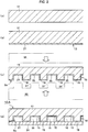
- first resin (R1) As the above-mentioned carbon material, at least one of carbon nanotubes, granular graphite, and carbon fibers were added. Further, to the first resin, a carbon material was included and a sheet-shaped first conductor part 11 was formed (step of FIG. 2(a) ).
- a second resin (R2) with a melting point lower than the above-mentioned first resin (R1) was prepared.
- This second resin is a resin used for facilitating hot melt bonding.
- the second resin corresponds to an adhesive of the first conductor part 11. If considering the compatibility of the second resin (R2) and the first resin (R1), the difficulty in peeling, etc., it is preferable to use a resin having a low melting point and the same in type as the first resin.
- the second resin (R2) can be selected from an acid-modified polyolefin resin.
- the acid-modified polyolefin resin a polyolefin-based resin modified by an unsaturated carboxylic acid or its derivative may be suitably used.
- an unsaturated carboxylic acid acrylic acid, methacrylic acid, maleic acid, fumaric acid, crotonic acid, itaconic acid, citraconic acid, etc. may be mentioned. Esters or anhydrides of these may also be used.
- methyl acrylate, methyl methacrylate, ethyl acrylate, propyl acrylate, butyl acrylate, butyl methacrylate, vinyl acetate, glycidyl acrylate, glycidyl methacrylate, acrylamide, methacrylamide, sodium acrylate, etc. may be mentioned.
- the polyolefin-based resin able to be used for the acid-modified polyolefin resin polyethylene, polypropylene, polybutene, and their copolymers, ethylene-vinyl acetate copolymer, ethylene-acrylic acid ester copolymers etc. may be mentioned.
- the amount of the unsaturated carboxylic acid or its derivative contained in the polyolefin-based resin is preferably 0.001 to 3 wt%, more preferably 0.01 to 1 wt%, particularly preferably 0.03 to 0.5 wt%.
- the amount of modification in the modified product is small, the effect of improvement of the interlayer adhesion is poor, while conversely if too great, a cross-linking reaction occurs and the shapeability becomes poor, so this is not preferred. Further, by mixing into these bondable resins polyisobutylene, ethylene-propylene rubber, or other rubber elastomer component or a polyolefin-based resin different from the polyolefin-based resin of the matrix of the bondable resin, the bondability is sometimes improved, so this is useful.
- the second resin (R2) also may have one or more of carbon nanotubes, granular graphite, and carbon fibers added to it as the above-mentioned carbon material. Further, a carbon material is included in the second resin and a sheet-shaped second conductor part 21 is formed. The second conductor part 21 is laid on at least one surface of the first conductor part 11. In this way, a sheet-shaped base part 13 is formed (step of FIG. 2(b) ).
- a mold 50 is prepared for forming the channels in the channel member.
- This mold 50 is formed with a relief grooved surface 51 in a comb tooth manner.
- the mold 50 is pressed against the surface of the flat sheet-shaped base part 13.
- the grooved surface 51 of the mold 50 is transferred to the base part 13 whereupon the groove parts 15 are formed.
- the other surface of the base part 13 is finished flat, so a separate flat plate-shaped mold 55 is prepared and pressed against the surface to which a grooved surface is not to be transferred.
- the pressing operation using the molds is performed at the stage where the resin forming the base part 13 is fluid.
- the grooved base part 16 provided with the groove parts 15 is formed (step of FIG. 2(c) ).
- groove parts 15 are provided at the surface to which the second conductor part 21 is laid.
- the groove parts are formed at this surface, so hot melt bonding with the sheet-shaped third conductor part and coverage of the groove parts explained later become easy.
- the grooved surface 51 of the illustrated mold 50 forms consecutive relief shapes.
- the ridges are parallel.
- the grooved surface 51 of the mold 50 is transferred to the base part 13 whereby the base part 13 is formed with relief-shaped groove parts Su comprised of consecutive parallel groove parts 15 (groove bottoms) and ridge parts 19.
- This shape is relatively easy to form and is less wasteful. Further, the burden in manufacture of the mold itself is lightened.
- the size of the relief-shaped groove parts is suitably determined, but the groove depth is 50 to 200 ⁇ m and the groove width is 100 to 400 ⁇ m. These thicknesses are suitable from the viewpoint of the cooling efficiency by supply of cooling medium to the inside of the fuel cell and the efficiency of supply and diffusion of hydrogen and oxygen to the separator and membrane electrode assembly.
- the relief-shaped groove parts are structures of consecutive parallel groove parts and ridge parts.
- the shape of the grooved surface of the mold is not limited to the illustrated one and can be made any necessary shape.
- the grooved surface may be made a continuous zigzag shape etc.
- a third resin (R3) with a melting point lower than the above-mentioned first resin (R1) is prepared.
- This third resin is a resin which melt bonds with the above-mentioned second conductor part.
- a resin having a lower melting point and the same in type as the first resin or a resin with a lower melting point and the same in type as the second resin is preferable to use a resin having a lower melting point and the same in type as the first resin or a resin with a lower melting point and the same in type as the second resin. This can be selected from acid-modified polyolefin resins similar to the second resin.
- the third resin (R3) as the above-mentioned carbon material, at least one of carbon nanotubes, granular graphite, and carbon fibers are added.
- a carbon material is contained and a sheet-shaped third conductor part 31 is formed. Further, the third conductor part 31 is laid on the surface of the grooved base part 16 where the groove parts 15 are formed. After being laid, the grooved base part 16 and the third conductor part 31 are heated to the melting temperature of the third resin of the third conductor part 31. By doing this, hot melt bonding occurs between the third conductor part 31 and the second conductor part at the grooved base part 16 side and the two are integrally joined (step of FIG. 2(d) ).
- the groove parts 15 of the grooved base part 16 are covered by the third conductor part 31. That is, the third conductor part 31 becomes lids of the groove parts 15. In this way, the parts of the groove parts 15 become pipeline-shaped fluid channels 18 whereby a channel member for fuel cell use 10A is formed.
- the second resin (R2) of the second conductor part 21 and the third resin (R3) of the third conductor part 31 have melting points lower than the first resin (R1) of the first conductor part 11, they melt relatively earlier than the first resin (R1).
- the second conductor part 21 and the third conductor part 31 of the grooved base part 16 melt bond.
- the first conductor part 11 of the grooved base part 16 remains holding its initial shape without melting. In this way, it is possible to utilize the difference in melting points to simply cover and close the groove parts.
- the melting point of a resin in the series of explanations above is a value found by differential scanning calorimetry (DSC). When there are two or more peak values in measurement, the value of the peak becoming relatively larger is employed for the melting point of the resin.
- predetermined amounts of the desired carbon material are weighed and kneaded by a heating- and melting-capable blender or kneader etc. so as to become uniform in the resin.
- the kneaded blend of the resins is coextruded from the T-die etc. and laid.
- the kneaded blend of the different resins is laid alone and run through a rolling roller etc. to a predetermined thickness. Suitable means and apparatuses for working the resin are used for these operations.
- FIG. 3 is a cross-sectional schematic view of a grooved base part 16b of a second embodiment.
- groove parts 15 first groove parts
- groove parts 17 second groove parts
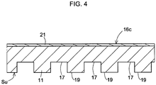
- FIG. 4 is a cross-sectional schematic view of a grooved base part 16c of a third embodiment.
- groove parts 17 are provided at the surface at the opposite side to the surface where the second conductor part 21 is laid. Note that, in an embodiment providing groove parts at the two surfaces like the grooved base part 16b, the directions of the grooves of the groove parts may be made the same ( FIG. 3(a) ) or may be made perpendicular (that is, may be deviated by predetermined angles) ( FIG. 3(b) ).
- the grooved base part 16b of the second embodiment it is possible to easily form a plurality of channels in the vertical direction by a single working operation.
- the grooved base part 16c of the third embodiment is convenient for combination with another grooved base part or another member inside the fuel cell. If using these grooved base parts, for example, it becomes possible to group together not only the channels for the cooling media, but also the channels for oxygen, channels for hydrogen, and other channels. This is helpful for reducing the volume of the members more.
- the second conductor parts 21 may also be laid at the two surfaces of the grooved base parts 16b, 16c (not shown). In this case, lamination by hot melt bonding becomes simpler.
- FIG. 5 is a cross-sectional schematic view of a channel member for fuel cell use 10B of a second embodiment.
- a grooved base part 16c (see FIGS. 3 and 4 ) is combined by being laid at the grooved base part 16b.
- the channel member for fuel cell use 10B is formed by hot melt bonding. If grasped from the illustration, at the center part, the groove parts 15 are closed whereby pipeline-shaped fluid channels 18 are formed. Further, groove parts 17, 15 are exposed at the two surfaces of the channel member for fuel cell use 10B in the vertical direction.
- the feature of this embodiment is that it is possible to form a hierarchy with the channels of other grooved base parts. Further, this is convenient for combination with other members in the fuel cell. In addition, these can also be utilized as groove parts for air-cooling.
- FIG. 5 as well, it is possible to lay second conductor parts 21 on the two surfaces as well (not shown).
- FIG. 6 is a cross-sectional schematic view of a channel member for fuel cell use 10C of a third embodiment.
- the groove parts are shaped as a succession of relief shapes and are large in groove widths.
- ridge parts 19 (between groove parts) of the grooved base part 16e formed with groove parts 15e at only a single surface are combined.
- design of the shape is easy.
- it is possible to change one grooved base part so as to suitably adjust the area of the vertical cross-section of the channels. For this reason, the convenience as a member assembled into a fuel cell is improved.
- second conductor parts 21 are laid at the two surfaces.
- FIG. 7 is a cross-sectional schematic view of a channel member for fuel cell use 10D of a fourth embodiment
- FIG. 8 is a cross-sectional schematic view of a channel member for fuel cell use 10E of a fifth embodiment.
- a metal sheet 40 is provided inside of the grooved base parts 16f and 16g.
- the metal sheet is utilized as a holding part when connecting and fastening the channel member for fuel cell use to the fuel cell. Further, electrons can move inside the metal sheet, so this is connected with outside wiring. For example, this is effective for serial connection.
- corrosion resistance etc. are considered. Therefore, a stainless steel sheet, titanium sheet, aluminum sheet, or other metal sheet is used.
- a metal sheet obtained by gold plating, nickel plating, carbon plating, or otherwise surface treating the above-mentioned metal sheet is also preferably used.
- the thickness of the metal sheet is about 8 to 200 ⁇ m in range. If the metal sheet becomes thinner, the volume of the fuel cell itself can be reduced and the power generating performance per cell volume can be raised.
- an adhesive resin layer 45 is interposed between the first resin (R1) and the metal sheet 40 of the grooved base part 16f (16g). The adhesive resin layer improves the bondability of both the grooved base part and metal sheet.
- the resin forming the adhesive resin layer 45 is selected from the acid-modified polyolefin resins of the composition of the above-mentioned second resin (R2) or third resin (R3).
- an acid-modified polyolefin resin is a polyolefin-based resin modified by an unsaturated carboxylic acid or a derivative of the same. Illustration of the types of resins used is omitted since the explanations would overlap.
- To the resin of the adhesive resin layer 45 as the carbon material, one or more of carbon nanotubes, granular graphite, and carbon fibers are added. This is to raise the conductivity of the adhesive resin layer 45 itself.
- the thickness of the adhesive resin layer 45 is adjusted at the extrusion and rolling stages. Note that, if made too thick, the conductivity deteriorates even if a carbon material is included. Therefore, the thickness of the adhesive resin layer 45 is generally made 100 ⁇ m or less, more preferably 50 ⁇ m or less.
- the adhesive resin layer 45 and the metal sheet 40 are bonded by hot melt bonding, so the resin is strongly stuck to the metal.
- the acid-modified polyolefin resin has polar groups. Due to this, the bond becomes stronger due to the effect of ion bonds between the polar groups of the resin and the metal atoms.
- a resin sheet later forming the adhesive resin layer 45 is placed at both surfaces or one surface of the metal sheet 40. These are inserted between a heating plate and heating rollers and hot melt bonded. In this way, an integral unit of a metal sheet 40 and adhesive resin layer 45 is formed.
- a sheet-shaped first conductor part 11 is laid. Further, a sheet-shaped second conductor part 21 is also laid at the first conductor part 11.
- the first conductor part 11 and the second conductor part 21 may be laid with separate sheet-shaped articles overlaid or may be simultaneously extruded from a T-die etc.
- sheet-shaped base parts 13f, 13g provided with metal sheets 40 are formed. Grooved surfaces are transferred to the base parts 13f, 13g whereby the grooved base parts 16f, 16g are formed.
- FIG. 7 a grooved base part 16f provided with groove parts 15, 17 at the two surfaces is prepared.
- a third conductor part 31 is laid over the surface of the grooved base part 16f where the second conductor part 21 is laid. After that, in the same way, the groove parts 15 of the grooved base part 16f are covered by the third conductor part 31 by being integrally joined by hot melt bonding.
- FIG. 8 is an example corresponding to the above-mentioned FIG. 5 .
- Two members are formed: a grooved base part 16f provided with groove parts 15, 17 at its two surfaces and a grooved based part 16g provided with groove parts 15 at one surface.
- the surface of the grooved base part 16f where the second conductor part 21 is laid and the surface of the grooved base part 16g where the second conductor part 21 is laid are bonded together.
- the groove parts 15 of the grooved base part 16f are covered by the grooved base part 16g by being integrally joined by hot melt bonding.
- the second conductor parts 21 can be laid at the two surfaces (not shown).
- FIG. 9 is a cross-sectional schematic view of a channel member for fuel cell use 10F of a fifth embodiment.
- the metal sheet 40 is exposed to the outside.
- the adhesive resin layer 45, first conductor part 11 (first resin), and second conductor part 21 (second resin) are laid on the metal sheet 40 in that order. Further, the grooved surface is transferred and groove parts 15 are formed. Next, the third conductor part 31 is laid on the surface of the grooved base part 16h where the groove parts 15 are formed.
- the methods of working the channel members for fuel cell use 10D, 10E, and 10F disclosed in FIG. 7 to FIG. 9 are similar to that of the channel member for fuel cell use 10A (see FIG. 2 ).
- a channel member for fuel cell use secures conductivity while using a resin and further can be freely designed in shape. Therefore, it is possible to make it the optimal form for the part required in the fuel cell. Therefore, this can be effectively used not only for channels for water and other cooling media, but also the supply of oxygen and hydrogen and further the discharge of generated steam etc.
- homopolypropylene made by Japan Polypropylene Corporation, Novatec FL100A, melting point 161°C, below referred to as "PP" was used.
- the second resin or third resin with melting points lower than the first resin the following resins were used.
- Maleic anhydride-modified low density polyethylene made by Mitsubishi Chemical, Modic M504, melting point 121°C, below referred to as "modified LL"
- Low density polyethylene made by Ube-Maruzen Polyethylene, Umerit 4540F, melting point 134°C, below referred to as "LL"
- LL Low density polyethylene
- Carbon nanotubes made by Showa Denko, VGCF-X (fiber diameter: 10 to 15 nm, below referred to as "CNT”)
- Granular graphite made by Nippon Carbon, Nicabeads P25B-ZG (average particle size: 25 ⁇ m, true density: 2.17 g/cm 3 , below referred to as "SG”)
- Carbon fibers made by Mitsubishi Plastics, Dialead K223HE (fiber diameter: 11 ⁇ m, true density: 2.0 g/cm 3 , below referred to as "CF"
- the following members were used:
- the mold for forming the groove parts was made a grooved surface of consecutive rectangular shapes (block shapes) in cross-sectional view with distances between grooves of 350 ⁇ m, groove widths of 200 ⁇ m, and groove depths of 100 ⁇ m.
- the mold for the flat surface was made a flat plate shape as is. The mold was made the same in all of the examples and comparative examples.
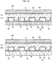
- FIG. 10(a) shows the case of laying a metal sheet 40, adhesive resin layer 45, first conductor part 11, and second conductor part 21 in that order to prepare a grooved base part 16x provided with groove parts 15.
- a metal sheet 40 provided with an adhesive resin layer 45 was laid and joined integrally by hot melt bonding (Structure [I]).
- FIG. 10(b) shows the case of laying a metal sheet 40, adhesive resin layer 45, first conductor part 11, and second conductor part 21 in that order to prepare a grooved base part 16x provided with groove parts 15.
- a composite 33 comprised of a sheet-shaped article 32 of a first resin containing a carbon material provided with a third conductor part 31 was laid and joined integrally by hot melt bonding (Structure [II]).
- FIG. 11(a) shows the case of laying a metal sheet 40, adhesive resin layer 45, first conductor part 11, and second conductor part 21 in that order to prepare a grooved base part 16x provided with groove parts 15. To this, just a metal sheet 40 was laid and joined integrally by hot melt bonding (Structure [III]).
- FIG. 11(b) shows the case of laying a metal sheet 40, adhesive resin layer 45, first conductor part 11, and second conductor part 21 in that order to prepare a grooved base part 16x provided with groove parts 15.
- a sheet-shaped article 32 of the first resin containing a carbon material was laid and joined integrally by hot melt bonding (Structure [IV]).
- FIG. 11(c) shows the case of laying a metal sheet 40, adhesive resin layer 45, and first conductor part 11 in that order to prepare a grooved base part 16y provided with groove parts 15.
- a metal sheet 40 provided with an adhesive resin layer 45 was laid and joined integrally by hot melt bonding (Structure [V]).
- a metal sheet gold-plated stainless steel sheet
- adhesive resin layer first conductor part
- second conductor part Between the second conductor part and mold, a release type PET film (thickness 25 ⁇ m) was sandwiched.
- molds provided with flat plate-shaped and grooved surfaces were used to hot press and bond the entire laminate.
- the press temperature at this time was set to a temperature 20°C higher than the melting point of the first resin (PP).
- the pressure of the press was made 30 MPa.
- a grooved base part was prepared in this way.
- the prepared groove parts had a distance between grooves of 350 ⁇ m, groove widths of 200 ⁇ m, and groove depths of 100 ⁇ m.
- a metal sheet gold-plated stainless steel sheet
- adhesive resin layer were laid and hot pressed from above and below using flat plate-shaped molds to join them.
- the press temperature at this time was set to a temperature 20°C higher than the melting point of the maleic anhydride-modified low density polyethylene (modified LL).
- the pressure of the press was made 30 MPa. In this way, a third conductor part provided with a metal sheet was prepared.
- the grooved base part and the third conductor part were integrally joined by hot pressing using flat plate-shaped molds from the top and bottom.
- hot pressing hot melt bonding
- the temperature was made 130°C and the press pressure was made 2.4 MPa.
- a channel member for fuel cell use of the Structure [I] of FIG. 10(a) was produced (Example 1).
- Example 2 used a grooved base part and third conductor part the same as the above-mentioned Example 1. At the time of hot pressing the grooved base part and third conductor part, the temperature was made 140°C and the press pressure was made 2.4 MPa. As a result, a channel member for fuel cell use of the Structure [I] of FIG. 10(a) was produced (Example 2).
- Example 3 used a grooved base part and third conductor part the same as the above-mentioned Example 1. At the time of hot pressing the grooved base part and third conductor part, the temperature was made 150°C and the press pressure was made 2.4 MPa. As a result, a channel member for fuel cell use of the Structure [I] of FIG. 10(a) was produced (Example 3).
- Example 4 used a grooved base part and third conductor part the same as the above-mentioned Example 1. At the time of hot pressing the grooved base part and third conductor part, the temperature was made 140°C and the press pressure was made 3.1 MPa. As a result, a channel member for fuel cell use of the Structure [I] of FIG. 10(a) was produced (Example 4).
- Example 5 used a first conductor part and third conductor part the same as the above-mentioned Example 1 and used as the resin of a second conductor part a low density polyethylene (LL).
- LL low density polyethylene
- CNT carbon nanotubes
- SG granular graphite
- a metal sheet (gold-plated stainless steel sheet), adhesive resin layer, first conductor part, and second conductor part were laid in that order. From above and below, molds provided with flat plate-shaped and grooved surfaces were used to hot press and bond the entire laminate. The press temperature at this time was set to a temperature 20°C higher than the melting point of the first resin (PP). The pressure of the press was made 30 MPa. A grooved base part was prepared in this way. Simultaneously, a metal sheet (gold-plated stainless steel sheet) and adhesive resin layer were laid. From above and below, flat plate-shaped molds were used to hot press and bond these.
- the press temperature at this time was set to a temperature 20°C higher than the melting point of the maleic anhydride-modified low density polyethylene (modified LL).
- the pressure of the press was made 30 MPa.
- a third conductor part provided with a metal sheet was prepared in this way.
- the grooved base part and third conductor part were integrally joined by hot pressing using flat plate-shaped molds from the top and bottom. At the time of hot pressing, the temperature was made 145°C and the press pressure was made 2.4 MPa. As a result, a channel member for fuel cell use of the Structure [I] of FIG. 10(a) was produced (Example 5).
- Example 6 the first conductor part and second conductor part were made the same as the above-mentioned Example 1 to prepare a grooved base part.
- the third conductor part was made a composite of a sheet-shaped article of the first resin containing a carbon material and the third conductor part.
- the sheet-shaped article of the first resin containing a carbon material was made the same as the first conductor part of Example 1.
- the third conductor part was made the same as the second conductor part of Example 5.
- this was passed through a calender roll machine heated to a temperature 1°C to 5°C lower than the melting point of the resin to obtain a thickness 20 ⁇ m sheet-shaped composite.
- the grooved base part and the composite becoming the third conductor part were integrally joined by hot pressing using flat plate-shaped molds from the top and bottom. At the time of hot pressing, the temperature was made 145°C and the press pressure was made 2.4 MPa. As a result, a channel member for fuel cell use of the Structure [II] of FIG. 10(b) was produced (Example 6).
- Example 7 The grooved base part and third conductor part in Example 7 were prepared in the same way as the above-mentioned Example 1. However, the two metal sheets used were changed from gold-plated stainless steel sheets to aluminum foils. That is, the third conductor part of Example 7 was an aluminum foil coated with an adhesive resin layer. At the time of hot pressing the grooved base part and third conductor part, the temperature was made 130°C and the press pressure was made 2.4 MPa. As a result, a channel member for fuel cell use of the Structure [I] of FIG. 10(a) was prepared (Example 7).
- Example 8 The grooved base part and third conductor part in Example 8 were prepared in the same way as the above-mentioned Example 1. However, the metal sheet laid on the grooved part side of the grooved base part was changed from a gold-plated stainless steel sheet to aluminum foil. That is, the third conductor part of Example 8 was also an aluminum foil coated with an adhesive resin layer. At the time of hot pressing the grooved base part and third conductor part, the temperature was made 130°C and the press pressure was made 2.4 MPa. As a result, a channel member for fuel cell use of the Structure [I] of FIG. 10(a) was prepared (Example 8).
- Comparative Example 1 the grooved base part and third conductor part were made the same as in the above-mentioned Example 1. At the time of hot pressing the grooved base part and third conductor part, the temperature was made 100°C and the press pressure was made 2.4 MPa. Therefore, while it was attempted to prepare a channel member for fuel cell use of Structure [I] of FIG. 10(a) , the two members could not be hot melt bonded (Comparative Example 1).
- Comparative Example 2 the grooved base part and third conductor part were made the same as in the above-mentioned Example 1. At the time of hot pressing the grooved base part and third conductor part, the temperature was made 165°C and the press pressure was made 2.4 MPa. As a result, a channel member for fuel cell use of the Structure [I] of FIG. 10(a) was produced (Comparative Example 2).
- Comparative Example 3 the grooved base part and third conductor part were made the same as in the above-mentioned Example 1. At the time of hot pressing the grooved base part and third conductor part, the temperature was made 140°C and the press pressure was made 4.1 MPa. As a result, a channel member for fuel cell use of the Structure [I] of FIG. 10(a) was produced (Comparative Example 3).
- Comparative Example 4 the first conductor part and second conductor part were made the same as in the above-mentioned Example 1 to prepare a grooved base part. Instead of the third conductor part, just a metal sheet (gold plated stainless steel sheet) was used. The grooved base part and the metal sheet were integrally joined by hot pressing using flat plate-shaped molds from the top and bottom. At the time of hot pressing, the temperature was made 140°C and the press pressure was made 2.5 MPa. As a result, a channel member for fuel cell use of the Structure [III] of FIG. 11(a) was produced (Comparative Example 4).
- Comparative Example 5 the members used were made the same as in Comparative Example 4. At the time of hot pressing, the temperature was made 140°C and the press pressure was made 3.5 MPa. As a result, a channel member for fuel cell use of the Structure [III] of FIG. 11(a) was produced (Comparative Example 5).
- Comparative Example 6 the first conductor part and second conductor part were made the same as in the above-mentioned Example 1 to prepare a grooved base part. Instead of the third conductor part, just a sheet-shaped article of the first resin was used. This sheet-shaped article of the first resin was made the same as in Example 6. The grooved base part and the sheet-shaped article of the first resin were integrally joined by hot pressing using flat plate-shaped molds from the top and bottom. At the time of hot pressing, the temperature was made 140°C and the press pressure was made 2.4 MPa. As a result, a channel member for fuel cell use of the Structure [IV] of FIG. 11(b) was produced (Comparative Example 6).
- Comparative Example 7 the members used were made the same as in Comparative Example 6. At the time of hot pressing, the temperature was made 165°C and the press pressure was made 2.4 MPa. As a result, a channel member for fuel cell use of the Structure [IV] of FIG. 11(b) was produced (Comparative Example 7).
- the second conductor part is omitted from the grooved base part of Example 1.
- a metal sheet gold-plated stainless steel sheet
- adhesive resin layer and first conductor part were laid in that order.
- molds provided with flat plate-shaped and grooved surfaces were used to hot press and bond the entire assembly.
- the press temperature at this time was set to a temperature 20°C higher than the melting point of the first resin (PP).
- the pressure of the press was made 30 MPa.
- a grooved base part without the second conductor part was prepared in this way.
- a third conductor part provided with a metal sheet the same as Example 1 was joined integrally by hot pressing using flat plate-shaped molds from the top and bottom.
- Channel members for fuel cell use of the examples and comparative examples were measured using a thickness measuring device (made by Toyo Seiki Seisaku-sho, B-1) to find their respective thicknesses ( ⁇ m).
- a film of a prototype for measurement was gripped from the thickness direction by diameter 30 mm gold-plated plates. It was pressed by 1 MPa and measured for the resistance (m ⁇ cm 2 ) in the thickness direction of the film.
- the channel members for fuel cell use of the examples were all evaluated as good in bonding. Further, the conductivities were confirmed from the values of the penetration resistances even after hot melt bonding along with hot pressing of the members. In addition, the examples changed in types of metal sheets as well could also be evaluated as good in bonding. The difference in the value of the penetration resistance can be considered to be the resistance of the metal sheet itself. Comparative Example 1 was low in temperature at the time of hot pressing and was insufficient in hot melt bonding of the resin, so was poor in bonding. Comparative Example 2 was high in temperature at the time of hot pressing. The resin of the grooved base part for forming the channels also softened and ended up changing in shape. Comparative Example 3 was high in pressure at the time of hot pressing and remarkably deformed in shape, so was poor.
- Comparative Example 4 the grooved base part had a second conductor part. Only a metal sheet was laid on this. Due to this, it was learned that the bonding is not sufficient with only melt bonding of the resin of the second conductor part. Comparative Example 5 had a pressure at the time of hot pressing further higher than even Comparative Example 4, but sufficient bonding could not be obtained.
- Comparative Example 6 is a sheet-shaped article of a first resin having a second conductor part at the grooved base part and containing a carbon material in this. Even if what was laid was a resin, it was learned that the bonding is not sufficient with only melt bonding of the resin of the second conductor part. Comparative Example 7 had a pressure at the time of hot pressing further higher than even Comparative Example 6, but sufficient bonding could not be obtained. Comparative Example 8 is an example of a grooved base part omitting the second conductor part and has a metal sheet bonded to this. A sufficient bonding could not be obtained even if providing an adhesive resin layer at the metal sheet side.
- the temperature at the time of the final hot pressing has to be made a temperature lower than the melting point of the resin of the main body part of the grooved base part and higher than the melting point of the resin contributing to bonding between the members. If considering these points, it is possible to suppress unintentional deformation of shape of members and possible to form good channels inside. Furthermore, good bondability was exhibited by hot melt bonding even if interposing a metal sheet in the members. Therefore, the channel member for fuel cell use can be said to be extremely high in convenience as a member built into a fuel cell.
Landscapes
- Chemical & Material Sciences (AREA)
- Engineering & Computer Science (AREA)
- General Chemical & Material Sciences (AREA)
- Manufacturing & Machinery (AREA)
- Chemical Kinetics & Catalysis (AREA)
- Life Sciences & Earth Sciences (AREA)
- Sustainable Development (AREA)
- Sustainable Energy (AREA)
- Electrochemistry (AREA)
- Composite Materials (AREA)
- Physics & Mathematics (AREA)
- Spectroscopy & Molecular Physics (AREA)
- Crystallography & Structural Chemistry (AREA)
- Inorganic Chemistry (AREA)
- Fuel Cell (AREA)
Claims (5)
- Procédé de production d'un membre de canal pour utilisation dans une pile à combustible (10A) comprenant :une étape d'obtention d'une première partie de conducteur en forme de feuille (11) contenant une première résine et un matériau carboné,une étape de couchage d'une deuxième partie de conducteur en forme de feuille (21) contenant une deuxième résine ayant un point de fusion inférieur à celui de ladite première résine et un matériau carboné sur au moins une surface de ladite première partie de conducteur (11) pour former une partie de base en forme de feuille (13),une étape de transfert d'une surface rainurée sur une surface de ladite partie de base (13) où ladite deuxième partie de conducteur (21) est couchée pour former une partie de base rainurée (16) dotée de parties de rainure (15),une étape de couchage d'une troisième partie de conducteur en forme de feuille (31) contenant un matériau carboné sur la surface de ladite partie de base rainurée (16) où lesdites parties de rainure (15) sont formées, etune étape de jonction solidaire de ladite partie de base rainurée (16) et de ladite troisième partie de conducteur (31) par collage par thermoenduction pour couvrir lesdites parties de rainure (15),caractérisé en ce queladite troisième partie de conducteur (31) contient en outre une troisième résine ayant un point de fusion inférieur à celui de ladite première résine, etla température au moment du collage par thermoenduction est une température inférieure au point de fusion de ladite première résine et supérieure au point de fusion de ladite deuxième résine et de ladite troisième résine et la pression au moment du collage par thermoenduction est inférieure à 4,1 MPa.
- Procédé de production d'un membre de canal pour utilisation dans une pile à combustible (10B) comprenant :une étape d'obtention d'une première partie de conducteur en forme de feuille (11) contenant une première résine et un matériau carboné,une étape de couchage d'une deuxième partie de conducteur en forme de feuille (21) contenant une deuxième résine ayant un point de fusion inférieur à celui de ladite première résine et un matériau carboné sur au moins une surface de ladite première partie de conducteur (11) pour former une partie de base en forme de feuille (13), etune étape de transfert d'une surface rainurée sur une surface de ladite partie de base (13) où ladite deuxième partie de conducteur (21) est couchée pour former une partie de base rainurée (16b) dotée de parties de rainure (15),caractérisé parune étape de formation d'une autre partie de base rainurée (16c) ayant la deuxième partie de conducteur (21) couchée sur au moins la surface du côté opposé à la surface où les parties de rainure (17) de ladite autre partie de base rainurée (16c) sont disposées,une étape de couchage de ladite autre partie de base rainurée (16c) sur la surface de ladite une partie de base rainurée (16b) où les parties de rainure (15) de ladite une partie de base rainurée (16b) sont formées de façon que la deuxième partie de conducteur (21) de ladite autre partie de base rainurée (16e) soit du côté des parties de rainure (15d) de ladite une partie de base rainurée (16d), etune étape de jonction solidaire de ladite une partie de base rainurée (16b) et de ladite autre partie de base rainurée (16c) par collage par thermoenduction pour couvrir les parties de rainure (15) de ladite une partie de base rainurée (16b),dans lequel la température au moment du collage par thermoenduction est une température inférieure au point de fusion de ladite première résine et supérieure au point de fusion de ladite deuxième résine et la pression au moment du collage par thermoenduction est inférieure à 4,1 MPa.
- Procédé de production d'un membre de canal pour utilisation dans une pile à combustible (10C) comprenant :une étape d'obtention d'une première partie de conducteur en forme de feuille (11) contenant une première résine et un matériau carboné,une étape de couchage d'une deuxième partie de conducteur en forme de feuille (21) contenant une deuxième résine ayant un point de fusion inférieur à celui de ladite première résine et un matériau carboné sur au moins une surface de ladite première partie de conducteur (11) pour former une partie de base en forme de feuille (13), etune étape de transfert d'une surface rainurée sur une surface de ladite partie de base (13) où ladite deuxième partie de conducteur (21) est couchée pour former une partie de base rainurée (16d) dotée de parties de rainure (15d),caractérisé parune étape de formation d'une autre partie de base rainurée (16e) ayant la deuxième partie de conducteur (21) couchée sur au moins la surface où les parties de rainure (15e) de ladite autre partie de base rainurée (16e) sont disposées,une étape de couchage de ladite autre partie de base rainurée (16e) sur la surface de ladite une partie de base rainurée (16d) où les parties de rainure (15d) de ladite une partie de base rainurée (16d) sont formées de façon que la deuxième partie de conducteur (21) de ladite autre partie de base rainurée (16e) soit du côté des parties de rainure (15d) de ladite une partie de base rainurée (16d), etune étape de jonction solidaire de ladite une partie de base rainurée (16d) et de ladite autre partie de base rainurée (16e) par collage par thermoenduction pour couvrir les parties de rainure (15d) de ladite une partie de base rainurée (16d),dans lequel la température au moment du collage par thermoenduction est une température inférieure au point de fusion de ladite première résine et supérieure au point de fusion de ladite deuxième résine et la pression au moment du collage par thermoenduction est inférieure à 4,1 MPa.
- Procédé de production d'un membre de canal pour utilisation dans une pile à combustible comprenant :une étape d'obtention d'une première partie de conducteur en forme de feuille (11) contenant une première résine et un matériau carboné,une étape de couchage d'une deuxième partie de conducteur en forme de feuille (21) contenant une deuxième résine ayant un point de fusion inférieur à celui de ladite première résine et un matériau carboné sur au moins une surface de ladite première partie de conducteur (11) pour former une partie de base en forme de feuille (13), etune étape de transfert d'une surface rainurée sur une surface de ladite partie de base (13) où ladite deuxième partie de conducteur (21) est couchée pour former une partie de base rainurée (16) dotée de parties de rainure (15),caractérisé parune étape de couchage d'une tôle métallique (40) dotée d'une couche de résine adhésive (45) sur la surface de ladite partie de base rainurée (16) où lesdites parties de rainure (15) sont formées de façon que la couche de résine adhésive (45) soit du côté desdites parties de rainure (15), etune étape de jonction solidaire de ladite partie de base rainurée (16) et de ladite tôle métallique (40) par collage par thermoenduction pour couvrir lesdites parties de rainure (15),dans lequelladite couche de résine adhésive (45) contient un matériau carboné et une résine adhésive choisie parmi les résines de polyoléfine modifiées par un acide ayant un point de fusion inférieur à celui de ladite première résine, etla température au moment du collage par thermoenduction est une température inférieure au point de fusion de ladite première résine et supérieure au point de fusion de ladite deuxième résine et de ladite résine adhésive et la pression au moment du collage par thermoenduction est inférieure à 4,1 MPa.
- Procédé de production d'un membre de canal pour utilisation dans une pile à combustible (10D ; 10E ; 10F) selon la revendication 1 ou 4, dans lequel
ladite première partie de conducteur (11) est couchée sur une tôle métallique (40) dotée d'une couche de résine adhésive (45) de façon que la couche de résine adhésive (45) soit du côté opposé à la surface où ladite deuxième partie de conducteur (21) est couchée,
ladite couche de résine adhésive (45) contient un matériau carboné et une résine adhésive choisie parmi les résines de polyoléfine modifiées par un acide ayant un point de fusion inférieur à celui de ladite première résine, et
la température au moment du collage par thermoenduction est une température supérieure au point de fusion de ladite résine adhésive.
Priority Applications (1)
| Application Number | Priority Date | Filing Date | Title |
|---|---|---|---|
| PL15859373T PL3220465T3 (pl) | 2014-11-10 | 2015-11-02 | Sposób wytwarzania elementu drogi przepływu dla ogniwa paliwowego |
Applications Claiming Priority (3)
| Application Number | Priority Date | Filing Date | Title |
|---|---|---|---|
| JP2014227989 | 2014-11-10 | ||
| JP2015209859A JP6277169B2 (ja) | 2014-11-10 | 2015-10-26 | 燃料電池用流路部材の製造方法 |
| PCT/JP2015/080932 WO2016076156A1 (fr) | 2014-11-10 | 2015-11-02 | Procédé de fabrication d'élément à circuit d'écoulement pour pile à combustible |
Publications (3)
| Publication Number | Publication Date |
|---|---|
| EP3220465A1 EP3220465A1 (fr) | 2017-09-20 |
| EP3220465A4 EP3220465A4 (fr) | 2018-05-23 |
| EP3220465B1 true EP3220465B1 (fr) | 2020-06-24 |
Family
ID=56071995
Family Applications (1)
| Application Number | Title | Priority Date | Filing Date |
|---|---|---|---|
| EP15859373.1A Active EP3220465B1 (fr) | 2014-11-10 | 2015-11-02 | Procédé de fabrication d'élément à circuit d'écoulement pour pile à combustible |
Country Status (7)
| Country | Link |
|---|---|
| US (3) | US10431839B2 (fr) |
| EP (1) | EP3220465B1 (fr) |
| JP (1) | JP6277169B2 (fr) |
| KR (1) | KR102489281B1 (fr) |
| CN (1) | CN107112550B (fr) |
| CA (1) | CA2961141C (fr) |
| PL (1) | PL3220465T3 (fr) |
Families Citing this family (8)
| Publication number | Priority date | Publication date | Assignee | Title |
|---|---|---|---|---|
| JP2018056048A (ja) * | 2016-09-30 | 2018-04-05 | トヨタ車体株式会社 | 燃料電池のセパレータ |
| CN109888321B (zh) * | 2019-01-21 | 2020-12-11 | 西安交通大学 | 燃料梯级利用物料分离传输燃料电池及其工作方法 |
| JP7413096B2 (ja) * | 2019-03-25 | 2024-01-15 | フタムラ化学株式会社 | フィルム状樹脂層を有する薄板状積層物の製造装置 |
| CN114303264A (zh) * | 2019-09-10 | 2022-04-08 | 上海旭济动力科技有限公司 | 燃料电池用的隔板、制造方法以及使用该隔板的燃料电池 |
| JP7404379B2 (ja) * | 2019-09-26 | 2023-12-25 | 東洋紡株式会社 | 燃料電池用接合体、及び積層体 |
| JP7533244B2 (ja) * | 2020-04-13 | 2024-08-14 | トヨタ車体株式会社 | 燃料電池用セパレータ及び燃料電池用セパレータの製造方法 |
| JP7306324B2 (ja) * | 2020-05-15 | 2023-07-11 | トヨタ車体株式会社 | 燃料電池用セパレータ及び燃料電池用セパレータの製造方法 |
| CN117280505A (zh) * | 2022-03-24 | 2023-12-22 | 信越聚合物株式会社 | 燃料电池用隔离件及其制造方法 |
Family Cites Families (23)
| Publication number | Priority date | Publication date | Assignee | Title |
|---|---|---|---|---|
| JPS5196720A (ja) | 1975-02-21 | 1976-08-25 | Niobuiritainetsugokin | |
| JP2000285930A (ja) | 1999-03-31 | 2000-10-13 | Mitsubishi Heavy Ind Ltd | 燃料電池用セパレータ及びその製造方法 |
| JP2003217611A (ja) * | 2001-11-19 | 2003-07-31 | Ntn Corp | 燃料電池用セパレータおよび燃料電池 |
| CA2492264A1 (fr) * | 2002-07-18 | 2004-01-29 | Honda Giken Kogyo Kabushiki Kaisha | Procede servant a fabriquer un separateur de pile a combustible et procede servant a accoupler ce separateur a une couche de diffusion d'electrode |
| JP2004235137A (ja) | 2002-12-04 | 2004-08-19 | Shin Etsu Polymer Co Ltd | 燃料電池用セパレータ及び成形品の製造方法 |
| JP2004273449A (ja) * | 2003-02-18 | 2004-09-30 | Unitika Ltd | 燃料電池用セパレータおよびその製造方法 |
| TW200522425A (en) | 2003-12-24 | 2005-07-01 | Showa Denko Kk | Separator for fuel cell and its manufacturing method |
| JP2005339874A (ja) | 2004-05-25 | 2005-12-08 | Dainippon Ink & Chem Inc | 燃料電池セパレータ製造用金型及びそれを用いてなる燃料電池セパレータの製造法 |
| JP2007134102A (ja) | 2005-11-09 | 2007-05-31 | Kyocera Chemical Corp | 導電性樹脂組成物、燃料電池用セパレータ及び燃料電池用セパレータの製造方法 |
| US8518603B2 (en) | 2005-12-05 | 2013-08-27 | Nanotek Instruments, Inc. | Sheet molding compound flow field plate, bipolar plate and fuel cell |
| JP5068052B2 (ja) * | 2006-09-29 | 2012-11-07 | 昭和電工株式会社 | 燃料電池用セパレータ、燃料電池用セルおよび燃料電池用セルユニット、ならびに燃料電池用セパレータおよび燃料電池用セルユニットの製造方法 |
| US20090017361A1 (en) | 2007-07-13 | 2009-01-15 | Dae Soon Lim | Separator for fuel cell and method for fabricating the same |
| JP2009093967A (ja) | 2007-10-10 | 2009-04-30 | Nippon Pillar Packing Co Ltd | 燃料電池用セパレータ |
| JP2009176545A (ja) | 2008-01-24 | 2009-08-06 | Toyota Motor Corp | 燃料電池の製造方法 |
| JP5548680B2 (ja) | 2009-03-30 | 2014-07-16 | 昭和電工株式会社 | シートプレス成形方法および燃料電池用セパレータの製造方法 |
| JP5413056B2 (ja) | 2009-08-25 | 2014-02-12 | 日産自動車株式会社 | 燃料電池用冷却層およびその製造方法ならびにそれを用いた燃料電池 |
| CN102714321B (zh) | 2009-11-13 | 2014-10-01 | 日产自动车株式会社 | 燃料电池及具有燃料电池的车辆 |
| JP2011171111A (ja) | 2010-02-18 | 2011-09-01 | Tokai Carbon Co Ltd | 燃料電池用セパレータの製造方法 |
| WO2012165492A1 (fr) * | 2011-05-30 | 2012-12-06 | 昭和電工株式会社 | Procédé de fabrication d'un séparateur de pile à combustible |
| JP5857213B2 (ja) | 2011-09-21 | 2016-02-10 | パナソニックIpマネジメント株式会社 | 燃料電池セパレータ成形用材料、燃料電池セパレータ、及び燃料電池 |
| JP5808290B2 (ja) * | 2012-05-29 | 2015-11-10 | 信越ポリマー株式会社 | 燃料電池用セパレータの製造方法及び燃料電池用セパレータの中間製品 |
| JP5930036B2 (ja) | 2012-07-11 | 2016-06-08 | トヨタ車体株式会社 | 燃料電池用セパレータ及び燃料電池用セパレータの製造方法 |
| CN105103351B (zh) * | 2013-04-11 | 2017-07-07 | 昭和电工株式会社 | 碳构件、碳构件的制造方法、氧化还原液流电池和燃料电池 |
-
2015
- 2015-10-26 JP JP2015209859A patent/JP6277169B2/ja active Active
- 2015-11-02 EP EP15859373.1A patent/EP3220465B1/fr active Active
- 2015-11-02 US US15/521,443 patent/US10431839B2/en active Active
- 2015-11-02 CN CN201580061076.8A patent/CN107112550B/zh active Active
- 2015-11-02 KR KR1020177011088A patent/KR102489281B1/ko active Active
- 2015-11-02 PL PL15859373T patent/PL3220465T3/pl unknown
- 2015-11-02 CA CA2961141A patent/CA2961141C/fr active Active
-
2019
- 2019-09-16 US US16/572,544 patent/US11158876B2/en active Active
- 2019-09-16 US US16/572,399 patent/US11158875B2/en active Active
Non-Patent Citations (1)
| Title |
|---|
| None * |
Also Published As
| Publication number | Publication date |
|---|---|
| CN107112550A (zh) | 2017-08-29 |
| EP3220465A1 (fr) | 2017-09-20 |
| CA2961141C (fr) | 2022-11-29 |
| US20200014050A1 (en) | 2020-01-09 |
| US20200014049A1 (en) | 2020-01-09 |
| EP3220465A4 (fr) | 2018-05-23 |
| US20170331137A1 (en) | 2017-11-16 |
| KR102489281B1 (ko) | 2023-01-18 |
| KR20170081174A (ko) | 2017-07-11 |
| CA2961141A1 (fr) | 2016-05-19 |
| JP6277169B2 (ja) | 2018-02-07 |
| JP2016096135A (ja) | 2016-05-26 |
| US11158876B2 (en) | 2021-10-26 |
| CN107112550B (zh) | 2020-12-01 |
| US11158875B2 (en) | 2021-10-26 |
| US10431839B2 (en) | 2019-10-01 |
| PL3220465T3 (pl) | 2021-01-11 |
Similar Documents
| Publication | Publication Date | Title |
|---|---|---|
| US11158876B2 (en) | Method of production of channel member for fuel cell | |
| CN103597641B (zh) | 燃料电池用隔板的制造方法 | |
| CN102257661B (zh) | 气体扩散层及其制造方法以及燃料电池 | |
| CN105103351B (zh) | 碳构件、碳构件的制造方法、氧化还原液流电池和燃料电池 | |
| US20170162878A1 (en) | Gas diffusion layer for fuel cell, fuel cell, and formation method for gas diffusion layer for fuel cell | |
| JP2005347256A (ja) | 電気化学的電池構成要素用の新規な密封剤 | |
| EP3598552B1 (fr) | Procédé de fabrication d'une pile à combustible et pile à combustible | |
| KR20220002646A (ko) | 연료 전지 판, 쌍극판 및 연료 전지 장치 | |
| CN102437301B (zh) | 用于聚合物电解质膜燃料电池的复合隔板及其制造方法 | |
| JP7725731B2 (ja) | 膜-電極-ユニットと、拡散層と、分配器プレートと、を備える電気化学セル、および電気化学セルを製造する方法 | |
| JP2016110724A (ja) | Pefcセパレータ用カーボン複合材及びその製造方法 | |
| JP2005243354A (ja) | 燃料電池用セパレータの製造方法 | |
| JP2014112475A (ja) | 燃料電池用セパレータの製造方法 | |
| JP4508574B2 (ja) | 燃料電池用セパレータ、燃料電池用セパレータの製造方法 | |
| WO2016076156A1 (fr) | Procédé de fabrication d'élément à circuit d'écoulement pour pile à combustible | |
| JP4650673B2 (ja) | 燃料電池用セパレータ材とその製造方法 | |
| JP2009093938A (ja) | 燃料電池セパレータ | |
| JP2009224272A (ja) | 燃料電池 | |
| JP7735398B2 (ja) | 燃料電池用セパレータおよびその製造方法 | |
| KR102643890B1 (ko) | 이차전지 파우치용 다층 필름 및 이의 제조방법 | |
| JP2014175285A (ja) | ガス拡散層、膜電極接合体、燃料電池、及びガス拡散層の製造方法 |
Legal Events
| Date | Code | Title | Description |
|---|---|---|---|
| STAA | Information on the status of an ep patent application or granted ep patent |
Free format text: STATUS: THE INTERNATIONAL PUBLICATION HAS BEEN MADE |
|
| PUAI | Public reference made under article 153(3) epc to a published international application that has entered the european phase |
Free format text: ORIGINAL CODE: 0009012 |
|
| STAA | Information on the status of an ep patent application or granted ep patent |
Free format text: STATUS: REQUEST FOR EXAMINATION WAS MADE |
|
| 17P | Request for examination filed |
Effective date: 20170322 |
|
| AK | Designated contracting states |
Kind code of ref document: A1 Designated state(s): AL AT BE BG CH CY CZ DE DK EE ES FI FR GB GR HR HU IE IS IT LI LT LU LV MC MK MT NL NO PL PT RO RS SE SI SK SM TR |
|
| AX | Request for extension of the european patent |
Extension state: BA ME |
|
| DAV | Request for validation of the european patent (deleted) | ||
| DAX | Request for extension of the european patent (deleted) | ||
| A4 | Supplementary search report drawn up and despatched |
Effective date: 20180425 |
|
| RIC1 | Information provided on ipc code assigned before grant |
Ipc: H01M 8/0202 20160101AFI20180419BHEP Ipc: H01M 8/02 20160101ALI20180419BHEP Ipc: H01M 8/10 20160101ALI20180419BHEP Ipc: H01M 8/026 20160101ALI20180419BHEP |
|
| STAA | Information on the status of an ep patent application or granted ep patent |
Free format text: STATUS: EXAMINATION IS IN PROGRESS |
|
| 17Q | First examination report despatched |
Effective date: 20190417 |
|
| GRAP | Despatch of communication of intention to grant a patent |
Free format text: ORIGINAL CODE: EPIDOSNIGR1 |
|
| STAA | Information on the status of an ep patent application or granted ep patent |
Free format text: STATUS: GRANT OF PATENT IS INTENDED |
|
| INTG | Intention to grant announced |
Effective date: 20200221 |
|
| GRAS | Grant fee paid |
Free format text: ORIGINAL CODE: EPIDOSNIGR3 |
|
| GRAA | (expected) grant |
Free format text: ORIGINAL CODE: 0009210 |
|
| STAA | Information on the status of an ep patent application or granted ep patent |
Free format text: STATUS: THE PATENT HAS BEEN GRANTED |
|
| AK | Designated contracting states |
Kind code of ref document: B1 Designated state(s): AL AT BE BG CH CY CZ DE DK EE ES FI FR GB GR HR HU IE IS IT LI LT LU LV MC MK MT NL NO PL PT RO RS SE SI SK SM TR |
|
| REG | Reference to a national code |
Ref country code: GB Ref legal event code: FG4D |
|
| REG | Reference to a national code |
Ref country code: CH Ref legal event code: EP |
|
| REG | Reference to a national code |
Ref country code: AT Ref legal event code: REF Ref document number: 1284798 Country of ref document: AT Kind code of ref document: T Effective date: 20200715 |
|
| REG | Reference to a national code |
Ref country code: DE Ref legal event code: R096 Ref document number: 602015054874 Country of ref document: DE |
|
| REG | Reference to a national code |
Ref country code: IE Ref legal event code: FG4D |
|
| REG | Reference to a national code |
Ref country code: CH Ref legal event code: NV Representative=s name: NOVAGRAAF INTERNATIONAL SA, CH |
|
| REG | Reference to a national code |
Ref country code: SE Ref legal event code: TRGR |
|
| REG | Reference to a national code |
Ref country code: FI Ref legal event code: FGE |
|
| REG | Reference to a national code |
Ref country code: NO Ref legal event code: T2 Effective date: 20200624 |
|
| PG25 | Lapsed in a contracting state [announced via postgrant information from national office to epo] |
Ref country code: LT Free format text: LAPSE BECAUSE OF FAILURE TO SUBMIT A TRANSLATION OF THE DESCRIPTION OR TO PAY THE FEE WITHIN THE PRESCRIBED TIME-LIMIT Effective date: 20200624 Ref country code: GR Free format text: LAPSE BECAUSE OF FAILURE TO SUBMIT A TRANSLATION OF THE DESCRIPTION OR TO PAY THE FEE WITHIN THE PRESCRIBED TIME-LIMIT Effective date: 20200925 |
|
| REG | Reference to a national code |
Ref country code: LT Ref legal event code: MG4D |
|
| PG25 | Lapsed in a contracting state [announced via postgrant information from national office to epo] |
Ref country code: BG Free format text: LAPSE BECAUSE OF FAILURE TO SUBMIT A TRANSLATION OF THE DESCRIPTION OR TO PAY THE FEE WITHIN THE PRESCRIBED TIME-LIMIT Effective date: 20200924 Ref country code: HR Free format text: LAPSE BECAUSE OF FAILURE TO SUBMIT A TRANSLATION OF THE DESCRIPTION OR TO PAY THE FEE WITHIN THE PRESCRIBED TIME-LIMIT Effective date: 20200624 Ref country code: RS Free format text: LAPSE BECAUSE OF FAILURE TO SUBMIT A TRANSLATION OF THE DESCRIPTION OR TO PAY THE FEE WITHIN THE PRESCRIBED TIME-LIMIT Effective date: 20200624 Ref country code: LV Free format text: LAPSE BECAUSE OF FAILURE TO SUBMIT A TRANSLATION OF THE DESCRIPTION OR TO PAY THE FEE WITHIN THE PRESCRIBED TIME-LIMIT Effective date: 20200624 |
|
| REG | Reference to a national code |
Ref country code: NL Ref legal event code: MP Effective date: 20200624 |
|
| REG | Reference to a national code |
Ref country code: AT Ref legal event code: MK05 Ref document number: 1284798 Country of ref document: AT Kind code of ref document: T Effective date: 20200624 |
|
| PG25 | Lapsed in a contracting state [announced via postgrant information from national office to epo] |
Ref country code: AL Free format text: LAPSE BECAUSE OF FAILURE TO SUBMIT A TRANSLATION OF THE DESCRIPTION OR TO PAY THE FEE WITHIN THE PRESCRIBED TIME-LIMIT Effective date: 20200624 Ref country code: NL Free format text: LAPSE BECAUSE OF FAILURE TO SUBMIT A TRANSLATION OF THE DESCRIPTION OR TO PAY THE FEE WITHIN THE PRESCRIBED TIME-LIMIT Effective date: 20200624 |
|
| PG25 | Lapsed in a contracting state [announced via postgrant information from national office to epo] |
Ref country code: AT Free format text: LAPSE BECAUSE OF FAILURE TO SUBMIT A TRANSLATION OF THE DESCRIPTION OR TO PAY THE FEE WITHIN THE PRESCRIBED TIME-LIMIT Effective date: 20200624 Ref country code: SM Free format text: LAPSE BECAUSE OF FAILURE TO SUBMIT A TRANSLATION OF THE DESCRIPTION OR TO PAY THE FEE WITHIN THE PRESCRIBED TIME-LIMIT Effective date: 20200624 Ref country code: EE Free format text: LAPSE BECAUSE OF FAILURE TO SUBMIT A TRANSLATION OF THE DESCRIPTION OR TO PAY THE FEE WITHIN THE PRESCRIBED TIME-LIMIT Effective date: 20200624 Ref country code: ES Free format text: LAPSE BECAUSE OF FAILURE TO SUBMIT A TRANSLATION OF THE DESCRIPTION OR TO PAY THE FEE WITHIN THE PRESCRIBED TIME-LIMIT Effective date: 20200624 Ref country code: RO Free format text: LAPSE BECAUSE OF FAILURE TO SUBMIT A TRANSLATION OF THE DESCRIPTION OR TO PAY THE FEE WITHIN THE PRESCRIBED TIME-LIMIT Effective date: 20200624 Ref country code: PT Free format text: LAPSE BECAUSE OF FAILURE TO SUBMIT A TRANSLATION OF THE DESCRIPTION OR TO PAY THE FEE WITHIN THE PRESCRIBED TIME-LIMIT Effective date: 20201026 |
|
| PG25 | Lapsed in a contracting state [announced via postgrant information from national office to epo] |
Ref country code: SK Free format text: LAPSE BECAUSE OF FAILURE TO SUBMIT A TRANSLATION OF THE DESCRIPTION OR TO PAY THE FEE WITHIN THE PRESCRIBED TIME-LIMIT Effective date: 20200624 Ref country code: IS Free format text: LAPSE BECAUSE OF FAILURE TO SUBMIT A TRANSLATION OF THE DESCRIPTION OR TO PAY THE FEE WITHIN THE PRESCRIBED TIME-LIMIT Effective date: 20201024 |
|
| REG | Reference to a national code |
Ref country code: DE Ref legal event code: R097 Ref document number: 602015054874 Country of ref document: DE |
|
| PG25 | Lapsed in a contracting state [announced via postgrant information from national office to epo] |
Ref country code: DK Free format text: LAPSE BECAUSE OF FAILURE TO SUBMIT A TRANSLATION OF THE DESCRIPTION OR TO PAY THE FEE WITHIN THE PRESCRIBED TIME-LIMIT Effective date: 20200624 |
|
| PLBE | No opposition filed within time limit |
Free format text: ORIGINAL CODE: 0009261 |
|
| STAA | Information on the status of an ep patent application or granted ep patent |
Free format text: STATUS: NO OPPOSITION FILED WITHIN TIME LIMIT |
|
| 26N | No opposition filed |
Effective date: 20210325 |
|
| PG25 | Lapsed in a contracting state [announced via postgrant information from national office to epo] |
Ref country code: MC Free format text: LAPSE BECAUSE OF FAILURE TO SUBMIT A TRANSLATION OF THE DESCRIPTION OR TO PAY THE FEE WITHIN THE PRESCRIBED TIME-LIMIT Effective date: 20200624 |
|
| PG25 | Lapsed in a contracting state [announced via postgrant information from national office to epo] |
Ref country code: LU Free format text: LAPSE BECAUSE OF NON-PAYMENT OF DUE FEES Effective date: 20201102 |
|
| REG | Reference to a national code |
Ref country code: BE Ref legal event code: MM Effective date: 20201130 |
|
| PG25 | Lapsed in a contracting state [announced via postgrant information from national office to epo] |
Ref country code: SI Free format text: LAPSE BECAUSE OF FAILURE TO SUBMIT A TRANSLATION OF THE DESCRIPTION OR TO PAY THE FEE WITHIN THE PRESCRIBED TIME-LIMIT Effective date: 20200624 |
|
| PG25 | Lapsed in a contracting state [announced via postgrant information from national office to epo] |
Ref country code: IE Free format text: LAPSE BECAUSE OF NON-PAYMENT OF DUE FEES Effective date: 20201102 |
|
| PG25 | Lapsed in a contracting state [announced via postgrant information from national office to epo] |
Ref country code: TR Free format text: LAPSE BECAUSE OF FAILURE TO SUBMIT A TRANSLATION OF THE DESCRIPTION OR TO PAY THE FEE WITHIN THE PRESCRIBED TIME-LIMIT Effective date: 20200624 Ref country code: MT Free format text: LAPSE BECAUSE OF FAILURE TO SUBMIT A TRANSLATION OF THE DESCRIPTION OR TO PAY THE FEE WITHIN THE PRESCRIBED TIME-LIMIT Effective date: 20200624 Ref country code: CY Free format text: LAPSE BECAUSE OF FAILURE TO SUBMIT A TRANSLATION OF THE DESCRIPTION OR TO PAY THE FEE WITHIN THE PRESCRIBED TIME-LIMIT Effective date: 20200624 |
|
| PG25 | Lapsed in a contracting state [announced via postgrant information from national office to epo] |
Ref country code: MK Free format text: LAPSE BECAUSE OF FAILURE TO SUBMIT A TRANSLATION OF THE DESCRIPTION OR TO PAY THE FEE WITHIN THE PRESCRIBED TIME-LIMIT Effective date: 20200624 |
|
| PG25 | Lapsed in a contracting state [announced via postgrant information from national office to epo] |
Ref country code: BE Free format text: LAPSE BECAUSE OF NON-PAYMENT OF DUE FEES Effective date: 20201130 |
|
| REG | Reference to a national code |
Ref country code: CH Ref legal event code: U11 Free format text: ST27 STATUS EVENT CODE: U-0-0-U10-U11 (AS PROVIDED BY THE NATIONAL OFFICE) Effective date: 20251201 |
|
| PGFP | Annual fee paid to national office [announced via postgrant information from national office to epo] |
Ref country code: DE Payment date: 20251127 Year of fee payment: 11 |
|
| PGFP | Annual fee paid to national office [announced via postgrant information from national office to epo] |
Ref country code: GB Payment date: 20251120 Year of fee payment: 11 |
|
| PGFP | Annual fee paid to national office [announced via postgrant information from national office to epo] |
Ref country code: NO Payment date: 20251118 Year of fee payment: 11 |
|
| PGFP | Annual fee paid to national office [announced via postgrant information from national office to epo] |
Ref country code: IT Payment date: 20251128 Year of fee payment: 11 Ref country code: FI Payment date: 20251118 Year of fee payment: 11 |
|
| PGFP | Annual fee paid to national office [announced via postgrant information from national office to epo] |
Ref country code: FR Payment date: 20251120 Year of fee payment: 11 |
|
| PGFP | Annual fee paid to national office [announced via postgrant information from national office to epo] |
Ref country code: CH Payment date: 20251201 Year of fee payment: 11 Ref country code: SE Payment date: 20251119 Year of fee payment: 11 |
|
| PGFP | Annual fee paid to national office [announced via postgrant information from national office to epo] |
Ref country code: CZ Payment date: 20251017 Year of fee payment: 11 |
|
| PGFP | Annual fee paid to national office [announced via postgrant information from national office to epo] |
Ref country code: PL Payment date: 20251020 Year of fee payment: 11 |