EP3226237A2 - Ultrasound exposure device - Google Patents
Ultrasound exposure device Download PDFInfo
- Publication number
- EP3226237A2 EP3226237A2 EP17160914.2A EP17160914A EP3226237A2 EP 3226237 A2 EP3226237 A2 EP 3226237A2 EP 17160914 A EP17160914 A EP 17160914A EP 3226237 A2 EP3226237 A2 EP 3226237A2
- Authority
- EP
- European Patent Office
- Prior art keywords
- sound
- inlet opening
- opening
- horn
- sound inlet
- Prior art date
- Legal status (The legal status is an assumption and is not a legal conclusion. Google has not performed a legal analysis and makes no representation as to the accuracy of the status listed.)
- Granted
Links
Images


Classifications
-
- G—PHYSICS
- G10—MUSICAL INSTRUMENTS; ACOUSTICS
- G10K—SOUND-PRODUCING DEVICES; METHODS OR DEVICES FOR PROTECTING AGAINST, OR FOR DAMPING, NOISE OR OTHER ACOUSTIC WAVES IN GENERAL; ACOUSTICS NOT OTHERWISE PROVIDED FOR
- G10K11/00—Methods or devices for transmitting, conducting or directing sound in general; Methods or devices for protecting against, or for damping, noise or other acoustic waves in general
- G10K11/02—Mechanical acoustic impedances; Impedance matching, e.g. by horns; Acoustic resonators
- G10K11/025—Mechanical acoustic impedances; Impedance matching, e.g. by horns; Acoustic resonators horns for impedance matching
-
- G—PHYSICS
- G10—MUSICAL INSTRUMENTS; ACOUSTICS
- G10K—SOUND-PRODUCING DEVICES; METHODS OR DEVICES FOR PROTECTING AGAINST, OR FOR DAMPING, NOISE OR OTHER ACOUSTIC WAVES IN GENERAL; ACOUSTICS NOT OTHERWISE PROVIDED FOR
- G10K13/00—Cones, diaphragms, or the like, for emitting or receiving sound in general
Definitions
- the present invention relates to a sound system having a sound generator which has a main emission direction, and a horn in the form of a hollow body which widens in a funnel shape from a sound inlet opening to a sound outlet opening and which has at least a first planar side surface extending between the openings Sounder is arranged at or near the sound inlet opening.
- Such sonicators are used to voice alarm people in areas with loud ambient noise.
- tunnels but also in other open and closed spaces, such as train stations, airports, factory buildings and shipyards, situations may arise in which persons must be informed about dangers and must be led out of the danger zones by means of voice instructions.
- Information, voice announcements or voice instructions can be transmitted via sound equipment arranged on the walls and especially on the ceilings of the rooms.
- the loud noise levels usually associated with the hazardous situations caused by, for example, fire, running machinery or engines or screaming people, must be drowned out by the sound system so that the possibly life-saving instructions can be perceived by the people to be evacuated acoustically understandable.
- the device should be simple and inexpensive to produce and versatile.
- a sound system with a sound generator which has a main emission direction, with a horn in the form of a funnel-shaped widening from a sound inlet opening to a sound outlet opening hollow body having at least a first extending between the openings, flat side surface, wherein the sound generator or near the sound inlet opening, and wherein the sound generator is arranged immediately adjacent to the (first) planar side surface or an imaginary extension thereof in such a way that its main radiation direction is parallel to the (first) planar side surface from the sound inlet to the sound exit opening ,
- the main radiation direction of a sound generator is defined by the direction of the respective maximum sound level of the free sounder or the sound-generating element thereof (which is, for example, a vibrating diaphragm) at an arbitrary distance (within a predetermined range).
- This definition of the main emission direction is intended to preclude reflection and change in direction of the sound waves emanating from the sound-generating element in front of or in the region of the sound inlet opening
- the sounder converts an electrical signal into an acoustic signal.
- the acoustic signal has a frequency range of 20 Hz to 20 kHz.
- the generated acoustic signal passes through the sound inlet opening in the horn of the sound system. Due to the arrangement of the sounder at or near the sound inlet opening occur almost no interactions between the acoustic signal and the sound inlet opening. The acoustic signal is passed almost lossless in the horn of the sound system.
- the sounder "on” or “near the sound inlet opening” is arranged when the sounder is disposed directly in the sound inlet opening adjoins this or at a distance along the Hauptabstrahlraum having the order of the maximum diameter of the Sound inlet is or is smaller.
- the arrangement of the sound generator at or near the sound inlet orifice pursues the purpose of introducing the acoustic signal through the sound inlet into the horn and through it with virtually no loss, without intermediate deflection or backscattering of the sound waves emanating from the actual sound source (eg vibrating membrane) ,
- the distance of the sounder to the sound inlet opening should not exceed a value of 50 mm and preferably 1 mm or less.
- the horn-introduced acoustic signal propagates in the funnel-shaped horn in the form of sound waves. Because the sound generator is disposed immediately adjacent to the flat side surface and the main radiation direction of the sounder is parallel to the flat side surface from the sound entrance opening to the sound exit opening, the maximum (the maximum amplitude) of the wavefront propagates parallel to this flat side surface.
- This side surface may for example be mounted parallel to a wall or ceiling of a building.
- the generated sound pressure in the direction of radiation is not weakened by the flat side surface of the horn and corresponding walls or ceilings but by reflections at a very small angle, which cause no noticeable transit time differences, rather amplified, so that the acoustic signal is good and undistorted perceptible even at a great distance.
- immediateately adjacent to the flat side surface or an imaginary extension thereof is understood to mean that the sound generator is arranged as close as possible to the flat side surface.
- the sounder touches the flat side surface or its imaginary extension.
- a clear distance of up to 4 cm, preferably of at most 2 cm, between the sound generator and the flat side surface or its extension is understood, for example, as "immediately adjacent to the flat side surface or an imaginary extension thereof".
- the sound generator has a membrane whose main vibration direction corresponds to the main emission direction.
- the projection surface of the membrane measured perpendicularly to the main emission direction should then largely (more than 50%), preferably completely cover the cross-section of the sound entry opening. If the surface of the membrane projected in a plane perpendicular to the main emission direction is smaller than the cross section of the sound inlet opening, the surface of the membrane projected into the cross section of the sound inlet opening should adjoin the plane defined by the flat side surface of the horn or have at most a clear distance to this plane , which is less than half the maximum diameter of the projection surface of the membrane.
- the projection surface of such a vibrating membrane on the sound inlet opening may also be larger than the surface of the sound inlet opening, but should not be more than twice.
- the sound inlet opening is circular, wherein preferably the edge of the sound inlet opening, the flat side surface or an imaginary extension of the flat side surface tangent.
- the sound generator preferably has a circular or rotationally symmetrical membrane as a sound-generating element.
- the projected along the main emission in a plane perpendicular to this plane of the membrane is then in the sound inlet opening 5, or covers it.
- the symmetry axis of the membrane and the main emission direction then also coincide.
- the opening cross section of the sound outlet opening and the opening cross section of the sound inlet opening in each case perpendicular to the main emission, a ratio between 10: 1 and 500: 1, preferably between 50: 1 and 200: 1, particularly preferably 180: 1.
- the free (inner) cross section of the horn is rectangular, with the inner corners preferably having a radius of curvature of a few millimeters.
- the horn may have in its initial section, starting from the sound inlet opening of the shape of the sounder or its membrane adapted cross-section, so for example a circular cross-section, which then gradually, for example, within the first tenth of the horn length, merges into a rectangular cross-section. In this initial region, the above-defined flat surface of the horn would not be exactly flat, but would be a tangent to the cross section of the horn in this plane.
- At least one second side surface of the horn connecting the sound inlet opening and the sound outlet opening is arranged opposite to the first planar side surface which is not flat, but for example curved concavely outwards from the sound inlet opening to the sound outlet opening so that the free cross section of the horn progressively increases in the direction of the sound outlet opening.
- the axis of curvature lies parallel to the first plane and perpendicular to the main emission direction.
- the average radius of curvature is on the order of 1 to 3 times the length of the horn, i. H. the distance between sound inlet and sound outlet.
- the profile of the concave side surface is approximated to a hyperbolic function curve or can be described by a hyperbolic function.
- a horn of concrete embodiments are at a length of about 70 cm to 200 cm and a sound outlet opening of about 40 cm to 100 cm wide and a height of 20 cm to about 50 cm. The remaining dimensions result from the relative ratios given as preferred.
- the remaining side surfaces defining the rectangular cross-section of the horn may in turn be planar surfaces diverging from each other at a divergence angle of up to 60 °, preferably 40 ° to 50 °, whose planes are preferably perpendicular to the plane of the first side surface and enclose with the main emission in about half the divergence angle of the two side surfaces.
- the distance between the sound inlet opening and the sound outlet opening along the flat side surface of the funnel-shaped hollow body corresponds in one embodiment to 20 times to 200 times the maximum diameter of the sound inlet opening, preferably 20 times to 50 times the maximum diameter of the sound inlet opening. This ratio is of importance for a range of the sound system that is as large as possible in relation to the maximum sound radiation of the sound generator.
- a grid or a perforated plate is arranged, wherein the grid or the perforated plate preferably has an inclination angle between 60 ° and 70 °, preferably 65 °, with respect to the main emission.
- the distance of the grid or the perforated plate from the sound outlet opening is a maximum of 1/3, for example between 1/4 and 1/8 of the distance between the sound inlet and outlet opening.
- the grid or the perforated plate should prevent nesting of animals in the horn and clogging of the horn by debris, at the same time the grid or perforated plate should affect the emission characteristics of the horn as little as possible.
- the inventive design and arrangement of the grid or perforated plate has a low harmonic distortion and does not affect the sound quality of the sound system or only slightly.
- the grid or the perforated plate is arranged in a grid receiving area, wherein the grid or perforated plate is fixed with a plurality of countersunk screws in the grid receptacle.
- the recesses of the grid or the holes of the perforated plate are arranged such that the distance between the centers of adjacent recesses or holes of the grid or of the perforated plate is the same.
- the hole pattern may form a hexagonal pattern of equilateral triangles, and the maximum hole diameter may be, for example, 1 mm to 20 mm, preferably 3 mm.
- a fabric preferably a non-woven, is arranged between the grid and the sound inlet opening.
- the fabric or fleece protects the sounder during cleaning work on the horn and prevents ingress of water.
- the fabric, preferably the nonwoven is arranged on the side of the grating facing the sound inlet opening.
- the outer edges of the grid or perforated plate have an edge protection seal in their connection to the horn.
- the edge protection seal reduces the distortion factor and prevents the ingress of dirt.
- the sound outlet opening has a circumferential edge reinforcement.
- the circumferential edge reinforcement preferably in the form of a stiffening bead, contributes to the stiffening of the horn.
- the edge reinforcement contributes to the fact that the horn is not or only insignificantly deformed by the sound transmitted through it, and natural resonances of the horn are minimized.
- the sound generator is arranged in a housing which is open on one side, wherein the housing is preferably watertight and / or dust-tight.
- a preferably waterproof and / or dustproof housing protects the sound generator disposed in the housing from environmental influences and thus increases the life of the sounder.
- the open side of the housing releases the sound source, such as a membrane, which may still be protected by a soundproofing grid or mesh or fabric.
- the sound inlet opening having the end of the horn has, for example, a circumferential flange which surrounds or defines the inlet opening and can serve as a mounting flange for a sounder housing.
- the flange may, for example, be made in one piece with the horn. Alternatively, the horn and the flange may be composed of several parts.
- a mounting bracket with the funnel-shaped hollow body releasably and adjustably connected is, wherein the mounting bracket is designed so that it is the flat side surface of the horn in a small clearance of the side surface to the mounting wall, for example, between 1 cm and 10 cm, preferably about 1 cm to 7 cm, to a mounting surface and parallel to this holds.
- the clear distance should on the one hand take into account a possible projection of the sounder housing and on the other hand facilitate the mounting of the horn on a wall or ceiling.
- the distance should be sufficiently small so that reflections of the sound at the parallel to the flat side surface extending wall or ceiling in front of the sound outlet opening are possible only at very shallow angles, so that interfering interference can be prevented.
- the mounting bracket has two parallel aligned, U-shaped bracket for at least partially encompassing the hollow body and the webs connecting the two brackets together.
- Each of the mutually parallel brackets is used for at least partially gripping the hollow body on its outer side in the vicinity of the sound inlet opening or the sound outlet opening.
- the web connecting the two parallel-aligned webs extends in an assembled state along the connection between the sound inlet opening and the sound outlet opening.
- each of the U-shaped brackets has two legs, each with a slot and / or a lateral insertion for inserting a respective holding element in the slot, each two holding elements are arranged on the outside of each of two opposite side walls of the funnel-shaped horn.
- the mounting bracket is first attached to the wall or ceiling to which the sound system is to be mounted. Subsequently, the holding devices of the horn are brought into engagement with the respective slot and / or the respective insertion aid of the mounting bracket, so that the horn is suspended on the U-shaped brackets.
- the position of the retaining elements in the oblong holes is variable, so that the orientation of the sound system relative to the mounting bracket and the wall or ceiling is adjustable.
- the insertion aid is a dovetail-shaped opening which opens laterally into a slot.
- the mounting bracket made of metal and / or the sounder is also and independent of the funnel-shaped horn, which is typically made of plastic, releasably connected via a mounting bracket and / or a chain and / or a rope to the mounting bracket.
- the mounting bracket, the chain and / or the rope are fireproof.
- the mounting bracket, the chain and / or the rope can be made of metal. In this way, even in the event of a fire at the mounting location of the sound system, the sounder is prevented from falling off by the fuse via the mounting bracket, chain and / or cable fastened to the mounting bracket.
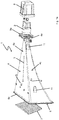
- FIG. 1 shows an embodiment of a sound system 1 according to the present invention, wherein the FIG. 1a an exploded view of the sound system 1 without mounting bracket, the Figure 1 b a mounting bracket 10 for engaging with the sound system 1 according to the FIG. 1a and the Figure 1c the sound system 1 from the FIG. 1a with the mounting bracket 10 off Figure 1 b demonstrate.
- the sounding device 1 has a horn 4 in the form of a funnel-shaped hollow body with a sound inlet opening 5 and a sound outlet opening 6.
- a first, planar side surface 4a extends up to the sound exit opening 6 opposite the sound inlet opening 5.
- a second side surface 4b concavely curved outwards from the sound inlet opening 5 to the sound outlet opening 6 connects the sound inlet opening 5 and the sound outlet opening 6th
- the cross section of the hollow body is rectangular throughout and widens from the sound inlet opening 5 to the sound outlet opening 6, wherein the sound inlet opening 5 has a circular opening cross-section, but which merges directly into a rectangular cross-section.
- the sound inlet opening 5 is a central, circular opening in a substantially flat flange plate 4e, which is flush with the end of the horn, which has a rectangular cross-section, or integrally connected thereto.
- the sound outlet opening 6 has a rectangular opening cross-section.
- the cross-sectional areas of sound inlet to sound outlet behave approximately as 1: 180, wherein the distance between sound inlet to sound outlet in about 20% to 60% greater than the width of the sound outlet, which in turn is about twice the height of this sound outlet.
- a sound generator 2 is arranged at or near the sound inlet opening 5, a sound generator 2 is arranged.
- the sound generator 2 has an opening, behind which a sound-generating membrane is arranged.
- the opening of the sounder 2 is arranged in alignment with the sound inlet opening 5, wherein the diameter of the opening of the sound generator 2 corresponds to the diameter of the sound inlet opening 5.
- the projected along the main radiation in a plane perpendicular to this plane surface of the membrane is in the sound inlet opening 5, or covers it. In general, then the symmetry axis of such, typically circular or rotationally symmetric membrane and the main emission direction coincide.
- the sounder 2 converts an electrical signal into an acoustic signal.
- the acoustic signal is passed through the sound inlet opening 5 in the horn 4. Since the sound generator 2 is arranged directly on the sound inlet opening 5, formed at the sound inlet opening 5 no significant reflections that could worsen the acoustic signal.
- the guided in the horn 4 acoustic signal propagates in the funnel-shaped hollow body.
- the sounder 2 is also arranged immediately adjacent to the flat side surface 4a or an imaginary extension of the same in such a way that its Schoabstrahlraum 3 parallel and low Distance from the flat side surface 4a of the sound inlet opening 5 to the sound outlet opening 6 extends.
- a housing 9 In order to protect the sounder 2 from external influences, this is arranged in a housing 9.
- the housing 9 is sealed with a seal 9a relative to the horn 4, so that the housing 9 is sealed watertight and dustproof.
- the sound exit opening 6 has a stiffening bead, i. a circumferential edge reinforcement 6c.
- the stiffening bead stiffens the sound outlet opening 6 and prevents it from being vibrated in a natural mode during operation.
- the inner corners 6a of the sound outlet opening 6 have a rounding 6b with a radius of a few millimeters.
- Grating 7 is arranged.
- the grille 7 is seated in a grating receptacle, for example in the form of flat grooves or protrusions, which are in the FIG. 1 are not shown, and is screwed with four retractable screws with the flat side surface 4a and the concave side surface 4b of the horn.
- the center distance between adjacent openings of the grating 7 is constant.
- the grating 7 is arranged at an angle of 65 ° to the flat side surface 4a and inclined in the direction of the sound inlet opening 5.
- the arranged on the flat side surface 4 a edge of the Grating 7 is located farther away from the sound entry opening 5 than the edge of the grating 7 arranged on the concave side surface 4b.
- the horn 4 has two holding devices 11 on its two opposite sides 4c and 4d.
- the holding devices 11 are wedge-shaped material reinforcements into which a screw or a threaded bolt with a nut can be screwed.
- Each two holding devices 11 are arranged in at the end of the horn 4 with the sound outlet opening 6 and the end of the horn 4 with the sound inlet opening 5.
- the provided for engaging with the holding devices 11 mounting bracket 10 is in the Figure 1 b shown.
- the mounting bracket 10 has two U-shaped bracket 10 a, which are aligned parallel to each other and are connected to each other via a web 10 b.
- Each bracket 10a has for the at least partially encompassing of the horn 4 two legs 10c with a slot 10d and an insertion 10e.
- the screwed into the holding device 11 screw is guided over the insertion 10e in the slot 10d.
- the position of the horn 4 relative to the mounting bracket 10 can be adjusted. Subsequently, the screws are tightened and connect the legs 10c firmly with the holding devices 11th
- FIG. 1c is the sound system 1 according to the FIG. 1a with a fixed mounting bracket 10 according to the Figure 1 b shown.
- the web 10b of the mounting bracket 10 extends in the direction of the sound inlet opening 5 to the sound outlet opening 6.
- the web 10b has a distance from the flat side surface 4a of the horn.
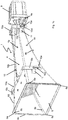
- FIG. 2 shows a horn 4 of another embodiment of a sound system 1 according to the present invention. That in the FIG. 2 shown horn 4 is for in the FIG. 1 Provided sounding device 1 shown, wherein in the FIG. 2a a side view, in the figure 2b is a plan view of the back of the sound inlet opening 5 and in the Figure 2c a plan view of the first, planar side surface 4a of the horn 4 are shown.
- first, planar side surface 4 a of the horn 4 extends from the sound inlet opening 5 to the sound outlet opening 6 and thus connects the sound inlet opening 5 with the sound outlet opening 6.
- a second, concave side surface 4b of the horn 4 is arranged.
- the second, concave side surface 4b connects the sound inlet opening 5 with the sound outlet opening 6 and forms together with the two other side surfaces 4c, 4d a funnel-shaped hollow body through which the acoustic signal is passed during operation of the sound system.
- the Indian FIG. 2 Sounder 2 is arranged close to or at the sound inlet opening 5 during operation of the sound reinforcement device.
- the sounder 2 is fixed to the flange 4e of the horn such that the sounder is disposed immediately adjacent to the flat side surface 4a or an imaginary extension of the flat side surface 4a and its Schoabstrahlraum parallel to the first, flat side surface 4a extends from the sound inlet opening 5 to the sound outlet opening 6.
- the flange 4e is also the attachment of a, in the FIG. 2 also not shown, housing 9, which protects the sounder 2 during operation of the sound system from environmental influences.
- each two holding devices 11 for engaging with a mounting bracket 10, which in the FIG. 2 not shown, arranged.
- the holding devices 11 are arranged such that in an operation of the sounding device, the web 10b of a mounting bracket 10 is arranged at a distance from the first, planar side surface 4a.
- the distance is selected so that the web 2 in a in the FIG. 2a shown side view at a height with the upper edge of the flange 4e completes.
- the horn 4 Surrounding the sound outlet opening 6, the horn 4 has an edge reinforcement 6c, which prevents the horn 4 is set in natural vibration in an operation of the sound system by the sound guided by the horn 4.
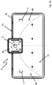
- the FIG. 2b shows the horn 4 in a plan view of the back of the sound inlet opening 5.
- the sound inlet opening 5 is a circular opening in the flange 4e.
- the diameter of the sound inlet opening 5 is preferably selected so that the diameter of a diaphragm of a sounder 2 corresponds, which is arranged in operation of the sound system at or near the sound inlet opening 5.
- the sound inlet opening 5 is arranged in the flange 4e such that the edge of the sound inlet opening 5 is located directly adjacent to the first, flat side surface 4a.
- FIGS. 2a and 2 B are in the Figure 2c showing a plan view of the first planar side surface 4a, the holding devices 11 mounted on each of the two side surfaces 4c, 4d for engaging with a mounting bracket 10 to recognize.
- the holding devices 11 are wedge-shaped material reinforcements of the side walls 4c, 4d.
Landscapes
- Physics & Mathematics (AREA)
- Engineering & Computer Science (AREA)
- Acoustics & Sound (AREA)
- Multimedia (AREA)
- Obtaining Desirable Characteristics In Audible-Bandwidth Transducers (AREA)
- Apparatuses For Generation Of Mechanical Vibrations (AREA)
- Transducers For Ultrasonic Waves (AREA)
- Circuit For Audible Band Transducer (AREA)
Abstract
Die vorliegende Erfindung betrifft eine Beschallungseinrichtung mit einem Schallgeber, welcher eine Hauptabstrahlrichtung aufweist, und mit einem Horn in Form eines sich von einer Schalleintrittsöffnung aus zu einer Schallaustrittsöffnung trichterförmig erweiternden Hohlkörpers, der zumindest eine erste sich zwischen den Öffnungen erstreckende, eben Seitenfläche aufweist, wobei der Schallgeber an oder nahe der Schalleintrittsöffnung angeordnet ist. Um Grenzflächenreflektionen zumindest zu reduzieren und um eine Beschallungseinrichtung mit einer gut ausgerichteten und wohldefinierten Schallwellenfront mit hohem Schalldruckpegel und einem ausgeglichen Frequenzgang bereitzustellen, wird erfindungsgemäß vorgeschlagen, dass der Schallgeber unmittelbar neben der (ersten) ebenen Seitenfläche oder einer gedachten Verlängerung derselben in der Weise angeordnet ist, dass seine Hauptabstrahlrichtung parallel zu der (ersten) ebenen Seitenfläche von der Schalleintritts- zu der Schallaustrittsöffnung hin verläuft.The present invention relates to a sound system having a sound generator which has a main emission direction, and a horn in the form of a hollow body which widens in a funnel shape from a sound inlet opening to a sound outlet opening and which has at least a first planar side surface extending between the openings Sounder is arranged at or near the sound inlet opening. To at least reduce surface reflections and to provide a sound system with a well-aligned and well-defined sound wave front with a high sound pressure level and a balanced frequency response, the invention proposes that the sound generator is arranged immediately adjacent to the (first) flat side surface or an imaginary extension thereof in the manner in that its main emission direction runs parallel to the (first) planar side surface from the sound inlet to the sound exit opening.
Description
Die vorliegende Erfindung betrifft eine Beschallungseinrichtung mit einem Schallgeber, welcher eine Hauptabstrahlrichtung aufweist, und mit einem Horn in Form eines sich von einer Schalleintrittsöffnung aus zu einer Schallaustrittsöffnung trichterförmig erweiternden Hohlkörpers, der zumindest eine erste sich zwischen den Öffnungen erstreckende, eben Seitenfläche aufweist, wobei der Schallgeber an oder nahe der Schalleintrittsöffnung angeordnet ist.The present invention relates to a sound system having a sound generator which has a main emission direction, and a horn in the form of a hollow body which widens in a funnel shape from a sound inlet opening to a sound outlet opening and which has at least a first planar side surface extending between the openings Sounder is arranged at or near the sound inlet opening.
Derartige Beschallungseinrichtungen dienen der Sprachalarmierung von Personen in Bereichen mit lauten Umgebungsgeräuschen. In Tunneln, aber auch in anderen offenen und geschlossenen Räumen, wie beispielsweise Bahnhöfen, Flughäfen, Fabrikhallen und Werfthallen, können Situationen auftreten, in denen Personen über Gefahren informiert und mittels Sprachanweisungen aus den Gefahrenbereichen geführt werden müssen. Informationen, Sprachdurchsagen oder Sprachanweisungen können über an den Wänden und insbesondere an den Decken der Räume angeordnete Beschallungseinrichtungen übermittelt werden. Die mit den Gefahrensituationen meist einhergehenden lauten Geräuschpegel, verursacht durch zum Beispiel Feuer, laufende Maschinen oder Motoren oder schreiende Personen, müssen durch die Beschallungseinrichtung übertönt werden, damit die möglicherweise lebensrettenden Anweisungen von den zu evakuierenden Personen akustisch verständlich wahrgenommen werden können.Such sonicators are used to voice alarm people in areas with loud ambient noise. In tunnels, but also in other open and closed spaces, such as train stations, airports, factory buildings and shipyards, situations may arise in which persons must be informed about dangers and must be led out of the danger zones by means of voice instructions. Information, voice announcements or voice instructions can be transmitted via sound equipment arranged on the walls and especially on the ceilings of the rooms. The loud noise levels usually associated with the hazardous situations caused by, for example, fire, running machinery or engines or screaming people, must be drowned out by the sound system so that the possibly life-saving instructions can be perceived by the people to be evacuated acoustically understandable.
Im Betrieb solcher Beschallungseinrichtungen kommt es aufgrund räumlicher Gegebenheiten oft zur Ausbildung von destruktiven Interferenzen, die zu einer Reichweitenreduzierung des akustischen Signals und zu einer Reduzierung der Signalqualität führen. Trifft das von der Beschallungseinrichtung ausgesendete akustische Signal auf eine Grenzfläche, wie beispielsweise eine Tunnelwand und/oder -decke, so wird ein Teil des auf die Grenzfläche auftretenden Schalls reflektiert. Eine in einem Abstand zu der Grenzfläche und der Beschallungseinrichtung befindliche Person nimmt sowohl das unmittelbar von dem Schallgeber ausgesendete Schallsignal als auch das von der Wand oder Decke reflektierte Schallsignal wahr. Der Laufzeitunterschied zwischen dem unmittelbar empfangenen und dem reflektierten Signal führt jedoch zu teilweise destruktiven Überlagerungen und Verzerrungen.Due to spatial conditions, the operation of such public address systems often leads to the formation of destructive interferences which lead to a reduction in the range of the acoustic signal and to a reduction of the signal quality. If the acoustic signal emitted by the sounding device strikes an interface, such as a tunnel wall and / or ceiling, a part of the sound occurring on the interface is reflected. A person located at a distance from the interface and the sound system perceives both the sound signal emitted directly by the sound generator and the sound signal reflected by the wall or ceiling. However, the skew between the immediately received and the reflected signal results in partially destructive overlays and distortions.
Demgegenüber besteht eine Aufgabe der vorliegenden Erfindung darin, eine Beschallungseinrichtung bereitzustellen, die Grenzflächenreflektionen zumindest reduziert, eine gut ausgerichtete und wohldefinierte Schallwellenfront mit hohem Schalldruckpegel und einen ausgeglichen Frequenzgang aufweist. Darüber hinaus sollte die Einrichtung einfach und kostengünstig herstellbar und vielfältig einsetzbar sein.In contrast, it is an object of the present invention to provide a sounding device that at least reduces interfacial reflections, a well-aligned and has a well-defined sound wave front with a high sound pressure level and a balanced frequency response. In addition, the device should be simple and inexpensive to produce and versatile.
Erfindungsgemäß wird eine Beschallungseinrichtung mit einem Schallgeber vorgeschlagen, welcher eine Hauptabstrahlrichtung aufweist, mit einem Horn in Form eines sich von einer Schalleintrittsöffnung aus zu einer Schallaustrittsöffnung trichterförmig erweiternden Hohlkörpers, der zumindest eine erste sich zwischen den Öffnungen erstreckende, ebene Seitenfläche aufweist, wobei der Schallgeber an oder nahe der Schalleintrittsöffnung angeordnet ist, und wobei der Schallgeber unmittelbar neben der (ersten) ebenen Seitenfläche oder einer gedachten Verlängerung derselben in der Weise angeordnet ist, dass seine Hauptabstrahlrichtung parallel zu der (ersten) ebenen Seitenfläche von der Schalleintritts- zu der Schallaustrittsöffnung hin verläuft.According to the invention, a sound system with a sound generator is proposed which has a main emission direction, with a horn in the form of a funnel-shaped widening from a sound inlet opening to a sound outlet opening hollow body having at least a first extending between the openings, flat side surface, wherein the sound generator or near the sound inlet opening, and wherein the sound generator is arranged immediately adjacent to the (first) planar side surface or an imaginary extension thereof in such a way that its main radiation direction is parallel to the (first) planar side surface from the sound inlet to the sound exit opening ,
Die Hauptabstrahlrichtung eines Schallgebers ist definiert durch die Richtung des jeweils maximalen Schallpegels des freien Schallgebers bzw. des schallerzeugenden Elementes desselben (das beispielsweise eine schwingende Membran ist) in einem (beliebigen) gegebenen Abstand (innerhalb einer vorgegebenen Reichweite). Diese Definition der Hauptabstrahlrichtung soll eine Reflexion und Richtungsänderung der von dem schallerzeugenden Element ausgehenden Schallwellen vor oder im Bereich der Schalleintrittsöffnung ausschließenThe main radiation direction of a sound generator is defined by the direction of the respective maximum sound level of the free sounder or the sound-generating element thereof (which is, for example, a vibrating diaphragm) at an arbitrary distance (within a predetermined range). This definition of the main emission direction is intended to preclude reflection and change in direction of the sound waves emanating from the sound-generating element in front of or in the region of the sound inlet opening
Der Schallgeber wandelt ein elektrisches Signal in ein akustisches Signal um. Vorzugsweise weist das akustische Signal einen Frequenzbereich von 20 Hz bis 20 kHz auf. Das erzeugte akustische Signal tritt durch die Schalleintrittsöffnung in das Horn der Beschallungseinrichtung. Durch die Anordnung des Schallgebers an oder nahe der Schalleintrittsöffnung treten nahezu keine Wechselwirkungen zwischen dem akustischen Signal und der Schalleintrittsöffnung auf. Das akustische Signal wird nahezu verlustfrei in das Horn der Beschallungseinrichtung geleitet.The sounder converts an electrical signal into an acoustic signal. Preferably, the acoustic signal has a frequency range of 20 Hz to 20 kHz. The generated acoustic signal passes through the sound inlet opening in the horn of the sound system. Due to the arrangement of the sounder at or near the sound inlet opening occur almost no interactions between the acoustic signal and the sound inlet opening. The acoustic signal is passed almost lossless in the horn of the sound system.
Als "Schalleintrittsöffnung" wird der kleinste freie Querschnitt des Hornes senkrecht zur Abstrahlrichtung und in Hauptabstrahlrichtung hinter dem Schallgeber angesehen. Im Sinne der vorliegenden Erfindung ist der Schallgeber "an" oder "nahe der Schalleintrittsöffnung" angeordnet, wenn der Schallgeber unmittelbar in der Schalleintrittsöffnung angeordnet ist, an diese angrenzt oder zu dieser einen Abstand entlang der Hauptabstrahlrichtung aufweist, der in der Größenordnung des maximalen Durchmessers der Schalleintrittsöffnung liegt oder kleiner ist. Die Anordnung des Schallgebers an oder nahe der Schalleintrittsöffnung verfolgt den Zweck eines nahezu verlustfreien Einleitens des akustischen Signals durch die Schalleintrittsöffnung in das Horn und durch dieses hindurch, ohne zwischenzeitliche Umlenkung oder Rückstreuung der von der eigentlichen Schallquelle (z. B. schwingenden Membran) ausgehenden Schallwellen. Der Abstand des Schallgebers zur Schalleintrittsöffnung sollte einen Wert von 50 mm nicht überschreiten und vorzugsweise 1 mm oder weniger betragen.As the "sound inlet opening" of the smallest free cross-section of the horn is considered perpendicular to the emission direction and in the main emission behind the sounder. For the purposes of the present invention, the sounder "on" or "near the sound inlet opening" is arranged when the sounder is disposed directly in the sound inlet opening adjoins this or at a distance along the Hauptabstrahlrichtung having the order of the maximum diameter of the Sound inlet is or is smaller. The arrangement of the sound generator at or near the sound inlet orifice pursues the purpose of introducing the acoustic signal through the sound inlet into the horn and through it with virtually no loss, without intermediate deflection or backscattering of the sound waves emanating from the actual sound source (eg vibrating membrane) , The distance of the sounder to the sound inlet opening should not exceed a value of 50 mm and preferably 1 mm or less.
Das in das Horn eingeleitete akustische Signal breitet sich in dem trichterförmigen Horn in Form von Schallwellen aus. Weil der Schallgeber unmittelbar neben der ebenen Seitenfläche angeordnet und die Hauptabstrahlrichtung des Schallgebers parallel zu der ebenen Seitenfläche von der Schalleintrittsöffnung zu der Schallaustrittsöffnung verläuft, breitet sich das Maximum (die maximale Amplitude) der Wellenfront parallel zu dieser ebenen Seitenfläche aus. Diese Seitenfläche kann beispielsweise parallel zu einer Wand oder Decke eines Bauwerks montiert sein. Dadurch werden Laufzeitunterschiede zwischen der direkten Wellenfront und Reflexionen mit der ebenen Seitenfläche und/oder der Wand weitestgehend vermieden bzw. auf sehr kleine Winkel beschränkt. Der erzeugte Schalldruck in Abstrahlrichtung wird durch die ebene Seitenfläche des Horns und entsprechende Wände oder Decken nicht geschwächt sondern durch Reflexionen unter sehr kleinem Winkel, die keine spürbaren Laufzeitunterschiede verursachen, eher verstärkt, sodass das akustische Signal auch in großer Entfernung gut und unverzerrt wahrnehmbar ist.The horn-introduced acoustic signal propagates in the funnel-shaped horn in the form of sound waves. Because the sound generator is disposed immediately adjacent to the flat side surface and the main radiation direction of the sounder is parallel to the flat side surface from the sound entrance opening to the sound exit opening, the maximum (the maximum amplitude) of the wavefront propagates parallel to this flat side surface. This side surface may for example be mounted parallel to a wall or ceiling of a building. As a result, runtime differences between the direct wavefront and reflections with the flat side surface and / or the wall are largely avoided or restricted to very small angles. The generated sound pressure in the direction of radiation is not weakened by the flat side surface of the horn and corresponding walls or ceilings but by reflections at a very small angle, which cause no noticeable transit time differences, rather amplified, so that the acoustic signal is good and undistorted perceptible even at a great distance.
Im Sinne der vorliegenden Erfindung wird unter "unmittelbar neben der ebenen Seitenfläche oder einer gedachten Verlängerung derselben" verstanden, dass der Schallgeber möglichst nahe an der ebenen Seitenfläche angeordnet ist.For the purposes of the present invention, "immediately adjacent to the flat side surface or an imaginary extension thereof" is understood to mean that the sound generator is arranged as close as possible to the flat side surface.
Vorzugsweise berührt der Schallgeber die ebene Seitenfläche bzw. deren gedachte Verlängerung. Ein lichter Abstand von bis zu 4 cm, vorzugsweise von höchstens 2 cm zwischen dem Schallgeber und der ebenen Seitenfläche bzw. deren Verlängerung wird beispielsweise noch als "unmittelbar neben der ebenen Seitenfläche oder einer gedachten Verlängerung derselben" verstanden.Preferably, the sounder touches the flat side surface or its imaginary extension. A clear distance of up to 4 cm, preferably of at most 2 cm, between the sound generator and the flat side surface or its extension is understood, for example, as "immediately adjacent to the flat side surface or an imaginary extension thereof".
Beispielsweise weist der Schallgeber eine Membran auf, deren Hauptschwingungsrichtung der Hauptabstrahlrichtung entspricht. Die zur Hauptabstrahlrichtung senkrecht gemessene Projektionsfläche der Membran sollte dann den Querschnitt der Schalleintrittsöffnung weitgehend (zu mehr als 50%), vorzugsweise vollständig überdecken. Ist die in eine Ebene senkrecht zur Hauptabstrahlrichtung projizierte Fläche der Membran kleiner als der Querschnitt der Schalleintrittsöffnung, sollte die in den Querschnitt der Schalleintrittsöffnung projizierte Fläche der Membran an die durch die ebene Seitenfläche des Hornes definierte Ebene angrenzen oder maximal einen lichten Abstand zur dieser Ebene haben, der geringer ist als der halbe maximale Durchmesser der Projektionsfläche der Membran. Die Projektionsfläche einer solchen schwingenden Membran auf die Schalleintrittsöffnung kann auch größer sein als die Fläche der Schalleintrittsöffnung, sollte jedoch nicht mehr als das Doppelte betragen.For example, the sound generator has a membrane whose main vibration direction corresponds to the main emission direction. The projection surface of the membrane measured perpendicularly to the main emission direction should then largely (more than 50%), preferably completely cover the cross-section of the sound entry opening. If the surface of the membrane projected in a plane perpendicular to the main emission direction is smaller than the cross section of the sound inlet opening, the surface of the membrane projected into the cross section of the sound inlet opening should adjoin the plane defined by the flat side surface of the horn or have at most a clear distance to this plane , which is less than half the maximum diameter of the projection surface of the membrane. The projection surface of such a vibrating membrane on the sound inlet opening may also be larger than the surface of the sound inlet opening, but should not be more than twice.
In einer Ausführungsform ist die Schalleintrittsöffnung kreisförmig, wobei vorzugsweise der Rand der Schalleintrittsöffnung die ebene Seitenfläche oder eine gedachte Verlängerung der ebenen Seitenfläche tangiert.In one embodiment, the sound inlet opening is circular, wherein preferably the edge of the sound inlet opening, the flat side surface or an imaginary extension of the flat side surface tangent.
Der Schallgeber weist vorzugsweise eine kreis- bzw. rotationsymmetrische Membran als schallerzeugendes Element auf. Die entlang der Hauptabstrahlrichtung in eine zu dieser senkrechten Ebene projizierte Fläche der Membran liegt dann in der Schalleintrittsöffnung 5, bzw. überdeckt diese. Im Allgemeinen fallen dann auch die Symmetrieachse der Membran und die Hauptabstrahlrichtung zusammen.The sound generator preferably has a circular or rotationally symmetrical membrane as a sound-generating element. The projected along the main emission in a plane perpendicular to this plane of the membrane is then in the sound inlet opening 5, or covers it. In general, the symmetry axis of the membrane and the main emission direction then also coincide.
In einer Ausführungsform haben der Öffnungsquerschnitt der Schallaustrittsöffnung und der Öffnungsquerschnitt der Schalleintrittsöffnung, jeweils senkrecht zur Hauptabstrahlrichtung, ein Verhältnis zwischen 10:1 und 500:1, vorzugsweise zwischen 50:1 und 200:1, besonders bevorzugt 180:1.In one embodiment, the opening cross section of the sound outlet opening and the opening cross section of the sound inlet opening, in each case perpendicular to the main emission, a ratio between 10: 1 and 500: 1, preferably between 50: 1 and 200: 1, particularly preferably 180: 1.
In einer Ausführungsform ist der freie (Innen-)Querschnitt des Hornes rechteckig, wobei die innenliegenden Ecken vorzugsweise einen Rundungsradius von einigen Millimetern aufweisen. Das Horn kann in seinem Anfangsabschnitt, ausgehend von der Schalleintrittsöffnung einen der Form des Schallgebers bzw. dessen Membran angepassten Querschnitt haben, also beispielsweise einen kreisförmigen Querschnitt, der dann allmählich, zum Beispiel innerhalb des ersten Zehntels der Hornlänge, in einen rechteckigen Querschnitt übergeht. In diesem Anfangsbereich wäre die oben definierte ebene Fläche des Hornes noch nicht exakt eben, jedoch läge eine Tangente an den Querschnitt des Hornes in dieser Ebene.In one embodiment, the free (inner) cross section of the horn is rectangular, with the inner corners preferably having a radius of curvature of a few millimeters. The horn may have in its initial section, starting from the sound inlet opening of the shape of the sounder or its membrane adapted cross-section, so for example a circular cross-section, which then gradually, for example, within the first tenth of the horn length, merges into a rectangular cross-section. In this initial region, the above-defined flat surface of the horn would not be exactly flat, but would be a tangent to the cross section of the horn in this plane.
In einer Ausführungsform ist mindestens eine zweite, die Schalleintrittsöffnung und die Schallaustrittsöffnung verbindende Seitenfläche des Hornes, gegenüberliegend zu der ersten ebenen Seitenfläche angeordnet, die nicht eben, sondern beispielsweise von der Schalleintrittsöffnung zu der Schallaustrittsöffnung nach außen konkav gekrümmt ist so dass der freie Querschnitt des Hornes in Richtung der Schallaustrittsöffnung progressiv zunimmt. Die Krümmungsachse liegt dabei parallel zu der ersten Ebene und senkrecht zur Hauptabstrahlrichtung. Der gemittelte Krümmungsradius liegt in der Größenordnung des 1- bis 3-fachen der Länge des Hornes, d. h. des Abstandes zwischen Schalleintritts- und Schallaustrittsöffnung. Vorzugsweise ist der Verlauf der konkaven Seitenfläche einem hyperbolischen Funktionsverlauf angenähert bzw. durch eine hyperbolische Funktion beschreibbar.In one embodiment, at least one second side surface of the horn connecting the sound inlet opening and the sound outlet opening is arranged opposite to the first planar side surface which is not flat, but for example curved concavely outwards from the sound inlet opening to the sound outlet opening so that the free cross section of the horn progressively increases in the direction of the sound outlet opening. The axis of curvature lies parallel to the first plane and perpendicular to the main emission direction. The average radius of curvature is on the order of 1 to 3 times the length of the horn, i. H. the distance between sound inlet and sound outlet. Preferably, the profile of the concave side surface is approximated to a hyperbolic function curve or can be described by a hyperbolic function.
Die Maße eines Horns von konkreten Ausführungsformen liegen bei einer Länge von ca. 70 cm bis 200 cm und einer Schallaustrittsöffnung von ca. 40 cm bis 100 cm Breite und einer Höhe von 20 cm bis etwa 50 cm. Die übrigen Maße ergeben sich dabei aus den als bevorzugt angegebenen relativen Verhältnissen.The dimensions of a horn of concrete embodiments are at a length of about 70 cm to 200 cm and a sound outlet opening of about 40 cm to 100 cm wide and a height of 20 cm to about 50 cm. The remaining dimensions result from the relative ratios given as preferred.
Die verbleibenden Seitenflächen, welche den rechteckigen Querschnitt des Hornes definieren, können ihrerseits ebene, unter einem Divergenzwinkel von bis zu 60°, vorzugsweise 40° bis 50°, voneinander divergierende Flächen sein, deren Ebenen vorzugsweise senkrecht zu der Ebene der ersten Seitenfläche stehen und die mit der Hauptabstrahlrichtung in etwa den halben Divergenzwinkel der beiden Seitenflächen einschließen.The remaining side surfaces defining the rectangular cross-section of the horn may in turn be planar surfaces diverging from each other at a divergence angle of up to 60 °, preferably 40 ° to 50 °, whose planes are preferably perpendicular to the plane of the first side surface and enclose with the main emission in about half the divergence angle of the two side surfaces.
Der Abstand zwischen der Schalleintrittsöffnung und der Schallaustrittsöffnung entlang der ebenen Seitenfläche des trichterförmigen Hohlkörpers entspricht in einer Ausführungsform einem 20-fachen bis 200-fachen des maximalen Durchmessers der Schalleintrittsöffnung, vorzugsweise einem 20-fachen bis 50-fachen des maximalen Durchmessers der Schalleintrittsöffnung. Dieses Verhältnis ist für eine im Verhältnis zu der maximalen Schallabstrahlung des Schallgebers möglichst große Reichweite der Beschallungseinrichtung von Bedeutung.The distance between the sound inlet opening and the sound outlet opening along the flat side surface of the funnel-shaped hollow body corresponds in one embodiment to 20 times to 200 times the maximum diameter of the sound inlet opening, preferably 20 times to 50 times the maximum diameter of the sound inlet opening. This ratio is of importance for a range of the sound system that is as large as possible in relation to the maximum sound radiation of the sound generator.
In einer Ausführungsform ist in dem freien Querschnitt des trichterförmigen Hohlkörpers im Abstand zu der Schallaustrittsöffnung ein Gitter oder ein Lochblech angeordnet, wobei das Gitter oder das Lochblech vorzugsweise einen Neigungswinkel zwischen 60° und 70°, vorzugsweise 65°, gegenüber der Hauptabstrahlrichtung aufweist. Vorzugsweise beträgt der Abstand des Gitters oder des Lochblechs von der Schallaustrittsöffnung maximal 1/3, zum Beispiel zwischen 1/4 und 1/8 des Abstandes zwischen Schalleintritts- und Austrittsöffnung.In one embodiment, in the free cross section of the funnel-shaped hollow body at a distance from the sound outlet opening, a grid or a perforated plate is arranged, wherein the grid or the perforated plate preferably has an inclination angle between 60 ° and 70 °, preferably 65 °, with respect to the main emission. Preferably, the distance of the grid or the perforated plate from the sound outlet opening is a maximum of 1/3, for example between 1/4 and 1/8 of the distance between the sound inlet and outlet opening.
In erster Linie soll das Gitter oder das Lochblech ein Einnisten von Tieren in dem Horn und ein Verstopfen des Horns durch Unrat verhindern, gleichzeitig soll das Gitter oder Lochblech die Abstrahlcharakteristik des Horns möglichst wenig beeinträchtigen. Die erfindungsgemäße Ausgestaltung und Anordnung des Gitters oder Lochbleches weist einen geringen Klirrfaktor auf und beeinträchtigt die Klangqualität der Beschallungseinrichtung nicht oder nur geringfügig.In the first place, the grid or the perforated plate should prevent nesting of animals in the horn and clogging of the horn by debris, at the same time the grid or perforated plate should affect the emission characteristics of the horn as little as possible. The inventive design and arrangement of the grid or perforated plate has a low harmonic distortion and does not affect the sound quality of the sound system or only slightly.
Vorzugsweise ist das Gitter oder das Lochblech in einem Gitteraufnahmebereich angeordnet, wobei das Gitter oder Lochblech mit einer Mehrzahl von versenkten Schrauben in der Gitteraufnahme fixiert ist. Vorzugsweise sind die Aussparungen des Gitters oder die Löcher des Lochblechs derart angeordnet, dass der Abstand zwischen den Mittelpunkten benachbarter Aussparungen oder Löcher des Gitters bzw. des Lochblechs gleich ist. Das Lochmuster kann beispielsweise ein hexagonales Muster aus gleichseitigen Dreiecken bilden und der maximale Lochdurchmesser liegt beispielsweise bei 1 mm bis 20 mm, vorzugsweise bei 3 mm.Preferably, the grid or the perforated plate is arranged in a grid receiving area, wherein the grid or perforated plate is fixed with a plurality of countersunk screws in the grid receptacle. Preferably, the recesses of the grid or the holes of the perforated plate are arranged such that the distance between the centers of adjacent recesses or holes of the grid or of the perforated plate is the same. For example, the hole pattern may form a hexagonal pattern of equilateral triangles, and the maximum hole diameter may be, for example, 1 mm to 20 mm, preferably 3 mm.
In einer Ausführungsform ist zwischen dem Gitter und der Schalleintrittsöffnung ein Gewebe, vorzugsweise ein Vlies, angeordnet. Das Gewebe oder Vlies schützt den Schallgeber bei Reinigungsarbeiten am Horn und verhindert ein Eindringen von Wasser. In einer Ausführungsform ist das Gewebe, vorzugsweise das Vlies, auf der der Schalleintrittsöffnung zugewandten Seite des Gitters angeordnet.In one embodiment, a fabric, preferably a non-woven, is arranged between the grid and the sound inlet opening. The fabric or fleece protects the sounder during cleaning work on the horn and prevents ingress of water. In one embodiment, the fabric, preferably the nonwoven, is arranged on the side of the grating facing the sound inlet opening.
In einer Ausführungsform weisen die Außenkanten des Gitters oder des Lochbleches in ihrer Verbindung zu dem Horn eine Kantenschutzdichtung auf. Die Kantenschutzdichtung vermindert den Klirrfaktor und verhindert ein Eindringen von Schmutz.In one embodiment, the outer edges of the grid or perforated plate have an edge protection seal in their connection to the horn. The edge protection seal reduces the distortion factor and prevents the ingress of dirt.
In einer Ausführungsform weist die Schallaustrittsöffnung eine umlaufende Randverstärkung auf. Die umlaufende Randverstärkung, vorzugsweise in Form eines Versteifungswulstes, trägt zur Versteifung des Horns bei. Im Betrieb der Beschallungseinrichtung trägt die Randverstärkung dazu bei, dass das Horn sich durch den hindurchgeleiteten Schall nicht oder nur unwesentlich verformt und Eigenresonanzen des Horns minimiert werden.In one embodiment, the sound outlet opening has a circumferential edge reinforcement. The circumferential edge reinforcement, preferably in the form of a stiffening bead, contributes to the stiffening of the horn. During operation of the acoustic irradiation device, the edge reinforcement contributes to the fact that the horn is not or only insignificantly deformed by the sound transmitted through it, and natural resonances of the horn are minimized.
In einer Ausführungsform ist der Schallgeber in einem einseitig offenen Gehäuse angeordnet, wobei das Gehäuse vorzugsweise wasserdicht und/oder staubdicht abgeschlossen ist. Ein vorzugsweises wasserdichtes und/oder staubdichtes Gehäuse schützt den in dem Gehäuse angeordneten Schallgeber vor Umwelteinflüssen und erhöht auf diese Weise die Lebensdauer des Schallgebers. Die offene Seite des Gehäuses lässt die Schallquelle, wie zum Beispiel eine Membran, frei, die noch durch ein den Schall nicht dämpfendes Schutzgitter oder Netz bzw. Gewebe geschützt sein kann.In one embodiment, the sound generator is arranged in a housing which is open on one side, wherein the housing is preferably watertight and / or dust-tight. A preferably waterproof and / or dustproof housing protects the sound generator disposed in the housing from environmental influences and thus increases the life of the sounder. The open side of the housing releases the sound source, such as a membrane, which may still be protected by a soundproofing grid or mesh or fabric.
Das die Schalleintrittsöffnung aufweisende Ende des Hornes weist beispielsweise einen umlaufenen Flansch auf, der die Eintrittsöffnung umgibt oder definiert und als Befestigungsflansch für ein Schallgebergehäuse dienen kann. Der Flansch kann beispielsweise einstückig mit dem Horn ausgeführt sein. Alternativ können das Horn und der Flansch mehrteilig zusammengesetzt sein.The sound inlet opening having the end of the horn has, for example, a circumferential flange which surrounds or defines the inlet opening and can serve as a mounting flange for a sounder housing. The flange may, for example, be made in one piece with the horn. Alternatively, the horn and the flange may be composed of several parts.
Um die Montage der Beschallungseinrichtung zu vereinfachen und/oder um eine Montage bei unterschiedlichen Gegebenheiten am Montageort zu ermöglichen und auch um die Beschallungseinrichtung im montieren Zustand ausrichten zu können, ist in einer Ausführungsform vorgesehen, dass ein Montagebügel mit dem trichterförmigen Hohlkörper lös- und einstellbar verbunden ist, wobei der Montagebügel so ausgelegt ist, dass er die ebene Seitenfläche des Hornes in einem kleinen lichten Abstand der Seitenfläche zu der Montagewand von beispielsweise zwischen 1 cm und 10 cm, vorzugsweise etwa 1 cm bis 7 cm, zu einer Montagefläche und parallel zu dieser hält. Der lichte Abstand soll einerseits einem möglichen Überstand des Schallgebergehäuses Rechnung tragen und andererseits auch die Montage des Hornes an einer Wand oder Decke erleichtern.In order to simplify the installation of the sound system and / or to allow mounting in different circumstances at the installation site and to align the sound system in the assembled state, is provided in one embodiment that a mounting bracket with the funnel-shaped hollow body releasably and adjustably connected is, wherein the mounting bracket is designed so that it is the flat side surface of the horn in a small clearance of the side surface to the mounting wall, for example, between 1 cm and 10 cm, preferably about 1 cm to 7 cm, to a mounting surface and parallel to this holds. The clear distance should on the one hand take into account a possible projection of the sounder housing and on the other hand facilitate the mounting of the horn on a wall or ceiling.
Weiterhin soll der Abstand genügend klein sein, so dass Reflexionen des Schalls an der parallel zu der ebenen Seitenfläche verlaufenden Wand oder Decke vor der Schallaustrittsöffnung nur unter sehr flachen Winkeln möglich sind, so dass störende Interferenzen verhindert werden.Furthermore, the distance should be sufficiently small so that reflections of the sound at the parallel to the flat side surface extending wall or ceiling in front of the sound outlet opening are possible only at very shallow angles, so that interfering interference can be prevented.
In einer Ausführungsform weist der Montagebügel zwei parallel zueinander ausgerichtete, U-förmige Bügel für ein zumindest abschnittsweises Umgreifen des Hohlkörpers und einen die zwei Bügel miteinander verbindenden Steg auf. Jeder der parallel zueinander ausgerichteten Bügel dient dem zumindest abschnittsweisen Umgreifen des Hohlkörpers auf seiner Außenseite in der Nähe der Schalleintrittsöffnung bzw. der Schallaustrittsöffnung. Der die zwei parallel ausgerichteten Bügel verbindende Steg erstreckt sich in einem montierten Zustand entlang der Verbindung zwischen der Schalleintrittsöffnung und Schallaustrittsöffnung.In one embodiment, the mounting bracket has two parallel aligned, U-shaped bracket for at least partially encompassing the hollow body and the webs connecting the two brackets together. Each of the mutually parallel brackets is used for at least partially gripping the hollow body on its outer side in the vicinity of the sound inlet opening or the sound outlet opening. The web connecting the two parallel-aligned webs extends in an assembled state along the connection between the sound inlet opening and the sound outlet opening.
In einer Ausführungsform weist jeder der U-förmigen Bügel zwei Schenkel mit je einem Langloch und/oder einer seitlichen Einführhilfe zum Einführen je eines Halteelementes in das Langloch auf, wobei je zwei Haltelemente auf der Außenseite jeder von zwei gegenüberliegenden Seitenwänden des trichterförmigen Hornes angeordnet sind. Für die Montage der Beschallungseinrichtung wird zunächst der Montagebügel an der Wand oder Decke befestigt, an der die Beschallungseinrichtung montiert werden soll. Anschließend werden die Haltevorrichtungen des Hornes mit dem jeweiligen Langloch und/oder der jeweiligen Einführhilfe des Montagebügels in Eingriff gebracht, so dass das Horn an den U-förmigen Bügeln aufgehängt ist. Die Position der Halteelemente in den Langlöchern ist veränderbar, sodass die Ausrichtung der Beschallungseinrichtung relativ zu dem Montagebügel und der Wand oder Decke einstellbar ist. In einer Ausführungsform ist die Einführhilfe eine schwalbenschwanzförmige Öffnung, die seitlich in ein Langloch mündet. Insbesondere eine Montage der Beschallungseinrichtung "über Kopf", d.h. an einer Decke und nachdem der Montagebügel bereits an der Decke montiert wurde, wird so vereinfacht.In one embodiment, each of the U-shaped brackets has two legs, each with a slot and / or a lateral insertion for inserting a respective holding element in the slot, each two holding elements are arranged on the outside of each of two opposite side walls of the funnel-shaped horn. For mounting the sound system, the mounting bracket is first attached to the wall or ceiling to which the sound system is to be mounted. Subsequently, the holding devices of the horn are brought into engagement with the respective slot and / or the respective insertion aid of the mounting bracket, so that the horn is suspended on the U-shaped brackets. The position of the retaining elements in the oblong holes is variable, so that the orientation of the sound system relative to the mounting bracket and the wall or ceiling is adjustable. In one embodiment, the insertion aid is a dovetail-shaped opening which opens laterally into a slot. In particular, mounting the sonicator "overhead", i. on a ceiling and after the mounting bracket has already been mounted on the ceiling, so is simplified.
In einer Ausführungsform ist der Montagebügel aus Metall und/oder der Schallgeber ist ebenfalls und unabhängig von dem trichterförmigen Horn, das typischerweise aus Kunststoff besteht, über einen Befestigungsbügel und/oder eine Kette und/oder ein Seil mit dem Montagebügel lösbar verbunden. Vorzugsweise sind der Befestigungsbügel, die Kette und/oder das Seil feuerfest. Beispielsweise können der Befestigungsbügel, die Kette und/oder das Seil aus Metall hergestellt sein. Auf diese Weise wird selbst bei einem Brand an dem Montageort der Beschallungseinrichtung ein Herabfallen des Schallgebers durch die Sicherung über den mit dem Montagebügel befestigten Befestigungsbügel, Kette und/oder Seil verhindert.In one embodiment, the mounting bracket made of metal and / or the sounder is also and independent of the funnel-shaped horn, which is typically made of plastic, releasably connected via a mounting bracket and / or a chain and / or a rope to the mounting bracket. Preferably, the mounting bracket, the chain and / or the rope are fireproof. For example, the mounting bracket, the chain and / or the rope can be made of metal. In this way, even in the event of a fire at the mounting location of the sound system, the sounder is prevented from falling off by the fuse via the mounting bracket, chain and / or cable fastened to the mounting bracket.
Weitere Vorteile, Merkmale und Anwendungsmöglichkeiten der vorliegenden Erfindung werden deutlich anhand der folgenden Beschreibung von bevorzugten Ausführungsformen und den dazugehörigen Figuren. Es zeigen:
- Figur 1a:
- eine Explosionsansicht einer erfindungsgemäßen Ausführungsform einer Beschallungseinrichtung;
- Figur 1b:
- eine perspektivische Ansicht auf einen Montagebügel zum in Eingriff bringen mit der Beschallungseinrichtung gemäß
Figur 1a ; - Figur 1c:
- zeigt eine Ansicht auf eine Beschallungseinrichtung gemäß
Figur 1a mit einem Montagebügel gemäßFigur 1 b; - Figur 2a:
- eine Seitenansicht auf ein Horn einer Beschallungseinrichtung gemäß einer weiteren Ausführungsform der Erfindung;
- Figur 2b
- eine Rückseitenansicht auf die Schalleintrittsöffnung des Horns gemäß der
Figur 2a ; - Figur 2c
- eine Draufsicht auf die erste, ebene Seitenfläche des Horns aus den
Figuren 2a und2b .
- FIG. 1a
- an exploded view of an embodiment of a public address device according to the invention;
- FIG. 1b
- a perspective view of a mounting bracket for engaging with the sound system according to
FIG. 1a ; - FIG. 1c:
- shows a view of a sound system according to
FIG. 1a with a mounting bracket according toFIG. 1 b; - FIG. 2a:
- a side view of a horn of a public address device according to another embodiment of the invention;
- FIG. 2b
- a rear view of the sound inlet opening of the horn according to the
FIG. 2a ; - Figure 2c
- a plan view of the first, planar side surface of the horn from the
FIGS. 2a and2 B ,
Die
Die Beschallungseinrichtung 1 weist ein Horn 4 in Form eines trichterförmigen Hohlkörpers mit einer Schalleintrittsöffnung 5 und einer Schallaustrittsöffnung 6 auf. Von der Schalleintrittsöffnung 5 erstreckt sich eine erste, ebene Seitenfläche 4a bis zu der Schallaustrittsöffnung 6. Gegenüberliegend zu der ersten, ebenen Seitenfläche 4a verbindet eine zweite, von der Schalleintrittsöffnung 5 zu der Schallaustrittsöffnung 6 nach außen konkav gekrümmte Seitenfläche 4b die Schalleintrittsöffnung 5 und die Schallaustrittsöffnung 6.The sounding
Der Querschnitt des Hohlkörpers ist durchgehend rechteckig und erweitert sich von der Schalleintrittsöffnung 5 hin zu der Schallaustrittsöffnung 6, wobei die Schalleintrittsöffnung 5 einen kreisförmigen Öffnungsquerschnitt aufweist, der aber unmittelbar in einen rechteckigen Querschnitt übergeht. Konkret ist die Schalleintrittsöffnung 5 eine zentrale, kreisförmige Öffnung in einer im Wesentlichen ebenen Flanschplatte 4e, die auf das Ende des Hornes, welches einen rechteckigen Querschnitt aufweist, bündig aufgesetzt bzw. einstückig mit diesem verbunden ist. Die Schallaustrittsöffnung 6 weist einen rechteckigen Öffnungsquerschnitt auf. Die Querschnittsflächen von Schalleintritts- zu Schallaustrittsöffnung verhalten sich etwa wie 1: 180, wobei der Abstand zwischen Schalleintritts- zu Schallaustrittsöffnung in etwa 20% bis 60% größer ist als die Breite der Schallaustrittsöffnung, die wiederum in etwa das Doppelte der Höhe dieser Schallaustrittsöffnung beträgt.The cross section of the hollow body is rectangular throughout and widens from the
An oder nahe der Schalleintrittsöffnung 5 ist ein Schallgeber 2 angeordnet. Der Schallgeber 2 weist eine Öffnung auf, hinter der eine schallerzeugende Membran angeordnet ist. Die Öffnung des Schallgebers 2 ist fluchtend zu der Schalleintrittsöffnung 5 angeordnet, wobei der Durchmesser der Öffnung des Schallgebers 2 dem Durchmesser der Schalleintrittsöffnung 5 entspricht. Die entlang der Hauptabstrahlrichtung in eine zu dieser senkrechten Ebene projizierte Fläche der Membran liegt in der Schalleintrittsöffnung 5, bzw. überdeckt diese. Im Allgemeinen fallen dann die Symmetrieachse einer solchen, typischerweise kreis- bzw. rotationsymmetrischen Membran und die Hauptabstrahlrichtung zusammen.At or near the
Im Betrieb wandelt der Schallgeber 2 ein elektrisches Signal in ein akustisches Signal um. Das akustische Signal wird durch die Schalleintrittsöffnung 5 in das Horn 4 geleitet. Da der Schallgeber 2 unmittelbar an der Schalleintrittsöffnung 5 angeordnet ist, entstehen an der Schalleintrittsöffnung 5 keine nennenswerten Reflexionen, die das akustische Signal verschlechtern könnten. Das in das Horn 4 geleitete akustische Signal breitet sich in dem trichterförmigen Hohlkörper aus. Um Reflexionen mit der ebenen Seitenfläche 4a des Horns 4 zu vermeiden bzw. auf sehr kleine Winkel zu beschränken, ist der Schallgeber 2 auch unmittelbar neben der ebenen Seitenfläche 4a oder einer gedachten Verlängerung derselben in der Weise angeordnet, dass seine Hauptabstrahlrichtung 3 parallel und in geringem Abstand zu der ebenen Seitenfläche 4a von der Schalleintrittsöffnung 5 zu der Schallaustrittsöffnung 6 verläuft.In operation, the sounder 2 converts an electrical signal into an acoustic signal. The acoustic signal is passed through the
Um den Schallgeber 2 vor äußeren Einflüssen zu schützen, ist dieser in einem Gehäuse 9 angeordnet. Das Gehäuse 9 ist mit einer Dichtung 9a gegenüber dem Horn 4 abgedichtet, sodass das Gehäuse 9 wasserdicht und staubdicht abgeschlossen ist.In order to protect the sounder 2 from external influences, this is arranged in a
Die Schallaustrittsöffnung 6 weist einen Versteifungswulst, d.h. eine umlaufende Randverstärkung 6c auf. Der Versteifungswulst versteift die Schallaustrittsöffnung 6 und verhindert, dass diese in einem Betrieb in Eigenschwingung versetzt wird. Die innenliegenden Ecken 6a der Schallaustrittsöffnung 6 weisen eine Rundung 6b mit einem Radius von wenigen Millimetern auf.The
Um ein Einnisten von Tieren in der Beschallungseinrichtung 1 zu verhindern, ist in einem maximalen Abstand von 1/3, hier in einem Abstand zwischen 1/4 bis 1/8 der Länge zwischen der Schalleintrittsöffnung 5 und der Schallaustrittsöffnung 6 von der Schallaustrittsöffnung 6 entfernt ein Gitter 7 angeordnet. Das Gitter 7 sitzt in einer Gitteraufnahme zum Beispiel in Form flacher Nuten oder Vorsprünge, die in der
Um die Beschallungseinrichtung 1 lös- und einstellbar mit einem Montagebügel 10 zu verbinden, weist das Horn 4 an seinen zwei gegenüberliegenden Seiten 4c und 4d jeweils zwei Haltevorrichtungen 11 auf. Bei der vorliegenden Ausführungsform sind die Haltevorrichtungen 11 keilförmige Materialverstärkungen in die eine Schraube oder ein Gewindebolzen mit einer Schraubenmutter eindrehbar sind. Je zwei Haltevorrichtungen 11 sind in an dem Ende des Horns 4 mit der Schallaustrittsöffnung 6 und dem Ende des Horns 4 mit der Schalleintrittsöffnung 5 angeordnet.In order to releasably and adjustably connect the sounding
Der zum in Eingriff bringen mit den Haltevorrichtungen 11 vorgesehene Montagebügel 10 ist in der
In der
Die
In der Seitenansicht der
Der in der
Neben der Befestigung des Schallgebers 2 dient der Flansch 4e auch der Anbringung eines, in der
An den gegenüberliegenden Seitenflächen 4d, 4c sind jeweils zwei Haltevorrichtungen 11 zum in Eingriff bringen mit einem Montagebügel 10, der in der
Umlaufend um die Schallaustrittsöffnung 6 weist das Horn 4 eine Randverstärkung 6c auf, die verhindert, dass das Horn 4 in einem Betrieb der Beschallungseinrichtung durch den durch das Horn 4 geführten Schall in Eigenschwingungen versetzt wird.Surrounding the
Die
In Ergänzung zu den
Für Zwecke der ursprünglichen Offenbarung wird darauf hingewiesen, dass sämtliche Merkmale, wie sie sich aus der vorliegenden Beschreibung, den Zeichnungen und den Ansprüchen für einen Fachmann erschließen, auch wenn sie konkret nur in Zusammenhang mit bestimmten weiteren Merkmalen beschrieben wurden, sowohl einzeln als auch in beliebigen Zusammenstellungen mit anderen der hier offenbarten Merkmale oder Merkmalsgruppen kombinierbar sind, soweit dies nicht ausdrücklich ausgeschlossen wurde oder technische Gegebenheiten derartige Kombinationen unmöglich oder sinnlos machen. Auf die umfassende, explizite Darstellung sämtlicher denkbarer Merkmalskombinationen wird hier nur der Kürze und der Lesbarkeit der Beschreibung wegen verzichtet.For purposes of the original disclosure, it is to be understood that all such features as will become apparent to those skilled in the art from the present description, drawings, and claims, even if concretely, only in connection with certain others Characteristics have been described, both individually and in any combination with other of the features or feature groups disclosed herein are combinable, unless this has been expressly excluded or technical conditions make such combinations impossible or pointless. On the comprehensive, explicit representation of all conceivable combinations of features is omitted here only for the sake of brevity and readability of the description.
Während die Erfindung im Detail in den Zeichnungen und der vorangehenden Beschreibung dargestellt und beschrieben wurde, erfolgt diese Darstellung und Beschreibung lediglich beispielhaft und ist nicht als Beschränkung des Schutzbereichs gedacht, so wie er durch die Ansprüche definiert wird. Die Erfindung ist nicht auf die offenbarten Ausführungsformen beschränkt.While the invention has been illustrated and described in detail in the drawings and the foregoing description, such illustration and description is exemplary only and is not intended to limit the scope of the protection as defined by the claims. The invention is not limited to the disclosed embodiments.
Abwandlungen der offenbarten Ausführungsformen sind für den Fachmann aus den Zeichnungen, der Beschreibung und den beigefügten Ansprüchen offensichtlich. In den Ansprüchen schließt das Wort "aufweisen" nicht andere Elemente oder Schritte aus, und der unbestimmte Artikel "eine" oder "ein" schließt eine Mehrzahl nicht aus. Die bloße Tatsache, dass bestimmte Merkmale in unterschiedlichen Ansprüchen beansprucht sind, schließt ihre Kombination nicht aus. Bezugszeichen in den Ansprüchen sind nicht als Beschränkung des Schutzbereichs gedacht.Variations of the disclosed embodiments will be apparent to those skilled in the art from the drawings, the description and the appended claims. In the claims, the word "comprising" does not exclude other elements or steps, and the indefinite article "a" or "an" does not exclude a plurality. The mere fact that certain features are claimed in different claims does not exclude their combination. Reference signs in the claims are not intended to limit the scope of protection.
- 11
- BeschallungseinrichtungPA facility
- 22
- Schallgebersounder
- 2a2a
- Membranmembrane
- 2b2 B
- HauptschwingungsrichtungMain vibration direction
- 33
- Hauptabstrahlrichtungmain radiation
- 44
- Hornhorn
- 4a4a
-
ebene Seitenfläche des Horns 4flat side surface of the
horn 4 - 4b4b
-
konkave Seitenfläche des Horns 4concave side surface of the
horn 4 - 4c4c
-
Seitenfläche des Horns 4Side surface of the
horn 4 - 4d4d
-
Seitenfläche des Horns 4Side surface of the
horn 4 - 4e4e
-
Flanschplatte des Horns 4Flange plate of the
horn 4 - 55
- SchalleintrittsöffnungSound inlet opening
- 66
- SchallaustrittsöffnungSound outlet
- 6a6a
-
Ecken der Schallaustrittsöffnung 6Corners of the
sound outlet opening 6 - 6b6b
-
Rundungen der Ecken 6a der Schallaustrittsöffnung 6Rounding the
corners 6a of the sound outlet opening. 6 - 6c6c
- Randverstärkung der Schallaustrittsöffnung 6Edge reinforcement of the sound outlet opening. 6
- 77
- Gittergrid
- 88th
- Lochblechperforated sheet
- 99
- Gehäusecasing
- 9a9a
- Dichtungpoetry
- 1010
- Montagebügelmounting bracket
- 10a10a
- U-förmiger Bügel des Montagebügels 10U-shaped bracket of the mounting bracket 10th
- 10b10b
-
Steg des Montagebügels 10Bridge of the mounting
bracket 10 - 10c10c
-
Schenkel des U-förmigen Bügels 10aLegs of the
U-shaped bracket 10a - 10d10d
-
Langloch in dem Schenkel 10cSlot in the
leg 10c - 10e10e
-
Einführhilfe in dem Schenkel 10cInsertion aid in the
leg 10c - 1111
- Haltevorrichtungholder
Claims (15)
Priority Applications (1)
| Application Number | Priority Date | Filing Date | Title |
|---|---|---|---|
| PL17160914T PL3226237T3 (en) | 2016-04-01 | 2017-03-14 | Sound producing device |
Applications Claiming Priority (1)
| Application Number | Priority Date | Filing Date | Title |
|---|---|---|---|
| DE102016106045.3A DE102016106045A1 (en) | 2016-04-01 | 2016-04-01 | PA facility |
Publications (3)
| Publication Number | Publication Date |
|---|---|
| EP3226237A2 true EP3226237A2 (en) | 2017-10-04 |
| EP3226237A3 EP3226237A3 (en) | 2017-12-27 |
| EP3226237B1 EP3226237B1 (en) | 2021-01-13 |
Family
ID=58387630
Family Applications (1)
| Application Number | Title | Priority Date | Filing Date |
|---|---|---|---|
| EP17160914.2A Active EP3226237B1 (en) | 2016-04-01 | 2017-03-14 | Sound producing device |
Country Status (4)
| Country | Link |
|---|---|
| EP (1) | EP3226237B1 (en) |
| DE (1) | DE102016106045A1 (en) |
| ES (1) | ES2846865T3 (en) |
| PL (1) | PL3226237T3 (en) |
Family Cites Families (13)
| Publication number | Priority date | Publication date | Assignee | Title |
|---|---|---|---|---|
| US718073A (en) * | 1902-09-24 | 1903-01-13 | Walter Barnes | Support for horns for talking-machines. |
| US898520A (en) * | 1907-08-27 | 1908-09-15 | Samuel D Solomon | Megaphone-holder for phonograph-cabinets. |
| US1532811A (en) * | 1924-08-29 | 1925-04-07 | Graham Edward Alfred | Cabinet for use with sound-reproducing devices |
| US4171678A (en) * | 1977-07-22 | 1979-10-23 | Midland-Ross Corporation | Air horn |
| JPS5834863Y2 (en) * | 1979-07-11 | 1983-08-05 | 松下電器産業株式会社 | horn speaker |
| JPS5890794U (en) * | 1981-12-15 | 1983-06-20 | 日本電音株式会社 | straight horn speaker |
| JPH02211798A (en) * | 1989-02-10 | 1990-08-23 | J F B:Kk | Horn speaker for woofer |
| JPH07322387A (en) * | 1994-05-24 | 1995-12-08 | Sony Corp | Audio equipment |
| US6516741B1 (en) * | 2000-09-12 | 2003-02-11 | Hadley Products | Leak proof apparatus for mounting components to panels |
| NL1019961C2 (en) * | 2002-02-14 | 2003-08-15 | Duran Audio B V | Acoustic reproducer. |
| DE10338539A1 (en) * | 2003-08-19 | 2005-03-31 | Ebe Elektro-Bau-Elemente Gmbh | Acoustic signal generator producing warning tone that is positioned by road lanes and is coupled to control computer |
| NL2011074C2 (en) * | 2013-07-01 | 2015-01-05 | Duran Audio B V | Sound speaker grill arrangement and sound speaker comprising such grill arrangement. |
| CN203596900U (en) * | 2013-11-26 | 2014-05-14 | 天津中环真美声学技术有限公司 | Gain guiding horn for loudspeaker |
-
2016
- 2016-04-01 DE DE102016106045.3A patent/DE102016106045A1/en not_active Withdrawn
-
2017
- 2017-03-14 ES ES17160914T patent/ES2846865T3/en active Active
- 2017-03-14 EP EP17160914.2A patent/EP3226237B1/en active Active
- 2017-03-14 PL PL17160914T patent/PL3226237T3/en unknown
Non-Patent Citations (1)
| Title |
|---|
| None |
Also Published As
| Publication number | Publication date |
|---|---|
| DE102016106045A1 (en) | 2017-10-05 |
| EP3226237B1 (en) | 2021-01-13 |
| ES2846865T3 (en) | 2021-07-29 |
| EP3226237A3 (en) | 2017-12-27 |
| PL3226237T3 (en) | 2021-08-16 |
Similar Documents
| Publication | Publication Date | Title |
|---|---|---|
| DE60115148T2 (en) | Speakers for ceilings with direct installation | |
| EP2063030A2 (en) | Device for fixing built-in sanitary elements | |
| DE102012107645B4 (en) | ACOUSTIC TRANSFORMER | |
| EP2734860B1 (en) | Composite assembly for a motor vehicle | |
| DE9311323U1 (en) | Sound absorbing device for a sound insulation wall | |
| EP1258848A2 (en) | Optical smoke detector | |
| EP3226237A2 (en) | Ultrasound exposure device | |
| CH707518B1 (en) | Metal frame | |
| EP0447936A2 (en) | Device for the fixation of installation elements | |
| DE19650522C2 (en) | Cone-shaped speaker attachment | |
| DE3529402C1 (en) | Method for monitoring the condition of spaces | |
| DE3420439C2 (en) | ||
| DE20112669U1 (en) | Sound absorbing panel | |
| DE2226306B2 (en) | Ultrasonic transmitter and receiver for outdoor use | |
| EP3910125A1 (en) | Support structure for suspending at least one sound absorber from a ceiling, system for improving the acoustics in a room | |
| EP3045607B1 (en) | Installation element for a skylight and skylight assembly with a skylight and installation element | |
| DE2721541A1 (en) | Connector for fixing grille ceiling member to wall - has U=section shoe fitting inside member and having mounting hooks to fit ceiling holes | |
| EP0418496A1 (en) | Electrical installation apparatus, especially safety socket | |
| EP2768238B1 (en) | Ceiling loudspeaker with a cover | |
| DE202015007639U1 (en) | Mounting device for attaching at least one object to a supporting device | |
| DE2523854A1 (en) | ACOUSTIC ALARM WITH SOUND ATTENUATION DEVICE | |
| DE202015005705U1 (en) | Speaker layout | |
| DE102010008409B4 (en) | Built-in part for receiving and / or fixing a poppet valve, ventilation grille or similar ventilation equipment | |
| AT10910U1 (en) | acoustical | |
| DE9313346U1 (en) | Cover for speakers |
Legal Events
| Date | Code | Title | Description |
|---|---|---|---|
| PUAI | Public reference made under article 153(3) epc to a published international application that has entered the european phase |
Free format text: ORIGINAL CODE: 0009012 |
|
| STAA | Information on the status of an ep patent application or granted ep patent |
Free format text: STATUS: THE APPLICATION HAS BEEN PUBLISHED |
|
| AK | Designated contracting states |
Kind code of ref document: A2 Designated state(s): AL AT BE BG CH CY CZ DE DK EE ES FI FR GB GR HR HU IE IS IT LI LT LU LV MC MK MT NL NO PL PT RO RS SE SI SK SM TR |
|
| AX | Request for extension of the european patent |
Extension state: BA ME |
|
| PUAL | Search report despatched |
Free format text: ORIGINAL CODE: 0009013 |
|
| AK | Designated contracting states |
Kind code of ref document: A3 Designated state(s): AL AT BE BG CH CY CZ DE DK EE ES FI FR GB GR HR HU IE IS IT LI LT LU LV MC MK MT NL NO PL PT RO RS SE SI SK SM TR |
|
| AX | Request for extension of the european patent |
Extension state: BA ME |
|
| RIC1 | Information provided on ipc code assigned before grant |
Ipc: G10K 13/00 20060101ALI20171117BHEP Ipc: G10K 11/02 20060101AFI20171117BHEP |
|
| STAA | Information on the status of an ep patent application or granted ep patent |
Free format text: STATUS: REQUEST FOR EXAMINATION WAS MADE |
|
| 17P | Request for examination filed |
Effective date: 20180416 |
|
| RBV | Designated contracting states (corrected) |
Designated state(s): AL AT BE BG CH CY CZ DE DK EE ES FI FR GB GR HR HU IE IS IT LI LT LU LV MC MK MT NL NO PL PT RO RS SE SI SK SM TR |
|
| STAA | Information on the status of an ep patent application or granted ep patent |
Free format text: STATUS: EXAMINATION IS IN PROGRESS |
|
| 17Q | First examination report despatched |
Effective date: 20190524 |
|
| GRAP | Despatch of communication of intention to grant a patent |
Free format text: ORIGINAL CODE: EPIDOSNIGR1 |
|
| STAA | Information on the status of an ep patent application or granted ep patent |
Free format text: STATUS: GRANT OF PATENT IS INTENDED |
|
| INTG | Intention to grant announced |
Effective date: 20201106 |
|
| GRAS | Grant fee paid |
Free format text: ORIGINAL CODE: EPIDOSNIGR3 |
|
| GRAA | (expected) grant |
Free format text: ORIGINAL CODE: 0009210 |
|
| STAA | Information on the status of an ep patent application or granted ep patent |
Free format text: STATUS: THE PATENT HAS BEEN GRANTED |
|
| AK | Designated contracting states |
Kind code of ref document: B1 Designated state(s): AL AT BE BG CH CY CZ DE DK EE ES FI FR GB GR HR HU IE IS IT LI LT LU LV MC MK MT NL NO PL PT RO RS SE SI SK SM TR |
|
| REG | Reference to a national code |
Ref country code: GB Ref legal event code: FG4D Free format text: NOT ENGLISH |
|
| REG | Reference to a national code |
Ref country code: CH Ref legal event code: EP |
|
| REG | Reference to a national code |
Ref country code: DE Ref legal event code: R096 Ref document number: 502017009026 Country of ref document: DE |
|
| REG | Reference to a national code |
Ref country code: IE Ref legal event code: FG4D Free format text: LANGUAGE OF EP DOCUMENT: GERMAN |
|
| REG | Reference to a national code |
Ref country code: AT Ref legal event code: REF Ref document number: 1355137 Country of ref document: AT Kind code of ref document: T Effective date: 20210215 |
|
| REG | Reference to a national code |
Ref country code: CH Ref legal event code: NV Representative=s name: ISLER AND PEDRAZZINI AG, CH |
|
| REG | Reference to a national code |
Ref country code: NL Ref legal event code: FP |
|
| REG | Reference to a national code |
Ref country code: LT Ref legal event code: MG9D |
|
| REG | Reference to a national code |
Ref country code: ES Ref legal event code: FG2A Ref document number: 2846865 Country of ref document: ES Kind code of ref document: T3 Effective date: 20210729 |
|
| PG25 | Lapsed in a contracting state [announced via postgrant information from national office to epo] |
Ref country code: HR Free format text: LAPSE BECAUSE OF FAILURE TO SUBMIT A TRANSLATION OF THE DESCRIPTION OR TO PAY THE FEE WITHIN THE PRESCRIBED TIME-LIMIT Effective date: 20210113 Ref country code: GR Free format text: LAPSE BECAUSE OF FAILURE TO SUBMIT A TRANSLATION OF THE DESCRIPTION OR TO PAY THE FEE WITHIN THE PRESCRIBED TIME-LIMIT Effective date: 20210414 Ref country code: FI Free format text: LAPSE BECAUSE OF FAILURE TO SUBMIT A TRANSLATION OF THE DESCRIPTION OR TO PAY THE FEE WITHIN THE PRESCRIBED TIME-LIMIT Effective date: 20210113 Ref country code: NO Free format text: LAPSE BECAUSE OF FAILURE TO SUBMIT A TRANSLATION OF THE DESCRIPTION OR TO PAY THE FEE WITHIN THE PRESCRIBED TIME-LIMIT Effective date: 20210413 Ref country code: PT Free format text: LAPSE BECAUSE OF FAILURE TO SUBMIT A TRANSLATION OF THE DESCRIPTION OR TO PAY THE FEE WITHIN THE PRESCRIBED TIME-LIMIT Effective date: 20210513 Ref country code: BG Free format text: LAPSE BECAUSE OF FAILURE TO SUBMIT A TRANSLATION OF THE DESCRIPTION OR TO PAY THE FEE WITHIN THE PRESCRIBED TIME-LIMIT Effective date: 20210413 Ref country code: LT Free format text: LAPSE BECAUSE OF FAILURE TO SUBMIT A TRANSLATION OF THE DESCRIPTION OR TO PAY THE FEE WITHIN THE PRESCRIBED TIME-LIMIT Effective date: 20210113 |
|
| PG25 | Lapsed in a contracting state [announced via postgrant information from national office to epo] |
Ref country code: SE Free format text: LAPSE BECAUSE OF FAILURE TO SUBMIT A TRANSLATION OF THE DESCRIPTION OR TO PAY THE FEE WITHIN THE PRESCRIBED TIME-LIMIT Effective date: 20210113 Ref country code: RS Free format text: LAPSE BECAUSE OF FAILURE TO SUBMIT A TRANSLATION OF THE DESCRIPTION OR TO PAY THE FEE WITHIN THE PRESCRIBED TIME-LIMIT Effective date: 20210113 Ref country code: LV Free format text: LAPSE BECAUSE OF FAILURE TO SUBMIT A TRANSLATION OF THE DESCRIPTION OR TO PAY THE FEE WITHIN THE PRESCRIBED TIME-LIMIT Effective date: 20210113 |
|
| PG25 | Lapsed in a contracting state [announced via postgrant information from national office to epo] |
Ref country code: IS Free format text: LAPSE BECAUSE OF FAILURE TO SUBMIT A TRANSLATION OF THE DESCRIPTION OR TO PAY THE FEE WITHIN THE PRESCRIBED TIME-LIMIT Effective date: 20210513 |
|
| REG | Reference to a national code |
Ref country code: DE Ref legal event code: R097 Ref document number: 502017009026 Country of ref document: DE |
|
| PG25 | Lapsed in a contracting state [announced via postgrant information from national office to epo] |
Ref country code: MC Free format text: LAPSE BECAUSE OF FAILURE TO SUBMIT A TRANSLATION OF THE DESCRIPTION OR TO PAY THE FEE WITHIN THE PRESCRIBED TIME-LIMIT Effective date: 20210113 Ref country code: CZ Free format text: LAPSE BECAUSE OF FAILURE TO SUBMIT A TRANSLATION OF THE DESCRIPTION OR TO PAY THE FEE WITHIN THE PRESCRIBED TIME-LIMIT Effective date: 20210113 Ref country code: EE Free format text: LAPSE BECAUSE OF FAILURE TO SUBMIT A TRANSLATION OF THE DESCRIPTION OR TO PAY THE FEE WITHIN THE PRESCRIBED TIME-LIMIT Effective date: 20210113 Ref country code: SM Free format text: LAPSE BECAUSE OF FAILURE TO SUBMIT A TRANSLATION OF THE DESCRIPTION OR TO PAY THE FEE WITHIN THE PRESCRIBED TIME-LIMIT Effective date: 20210113 |
|
| PLBE | No opposition filed within time limit |
Free format text: ORIGINAL CODE: 0009261 |
|
| STAA | Information on the status of an ep patent application or granted ep patent |
Free format text: STATUS: NO OPPOSITION FILED WITHIN TIME LIMIT |
|
| PG25 | Lapsed in a contracting state [announced via postgrant information from national office to epo] |
Ref country code: DK Free format text: LAPSE BECAUSE OF FAILURE TO SUBMIT A TRANSLATION OF THE DESCRIPTION OR TO PAY THE FEE WITHIN THE PRESCRIBED TIME-LIMIT Effective date: 20210113 Ref country code: SK Free format text: LAPSE BECAUSE OF FAILURE TO SUBMIT A TRANSLATION OF THE DESCRIPTION OR TO PAY THE FEE WITHIN THE PRESCRIBED TIME-LIMIT Effective date: 20210113 Ref country code: RO Free format text: LAPSE BECAUSE OF FAILURE TO SUBMIT A TRANSLATION OF THE DESCRIPTION OR TO PAY THE FEE WITHIN THE PRESCRIBED TIME-LIMIT Effective date: 20210113 |
|
| 26N | No opposition filed |
Effective date: 20211014 |
|
| PG25 | Lapsed in a contracting state [announced via postgrant information from national office to epo] |
Ref country code: LU Free format text: LAPSE BECAUSE OF NON-PAYMENT OF DUE FEES Effective date: 20210314 Ref country code: AL Free format text: LAPSE BECAUSE OF FAILURE TO SUBMIT A TRANSLATION OF THE DESCRIPTION OR TO PAY THE FEE WITHIN THE PRESCRIBED TIME-LIMIT Effective date: 20210113 Ref country code: IE Free format text: LAPSE BECAUSE OF NON-PAYMENT OF DUE FEES Effective date: 20210314 |
|
| PG25 | Lapsed in a contracting state [announced via postgrant information from national office to epo] |
Ref country code: SI Free format text: LAPSE BECAUSE OF FAILURE TO SUBMIT A TRANSLATION OF THE DESCRIPTION OR TO PAY THE FEE WITHIN THE PRESCRIBED TIME-LIMIT Effective date: 20210113 |
|
| PG25 | Lapsed in a contracting state [announced via postgrant information from national office to epo] |
Ref country code: IS Free format text: LAPSE BECAUSE OF FAILURE TO SUBMIT A TRANSLATION OF THE DESCRIPTION OR TO PAY THE FEE WITHIN THE PRESCRIBED TIME-LIMIT Effective date: 20210513 |
|
| PG25 | Lapsed in a contracting state [announced via postgrant information from national office to epo] |
Ref country code: HU Free format text: LAPSE BECAUSE OF FAILURE TO SUBMIT A TRANSLATION OF THE DESCRIPTION OR TO PAY THE FEE WITHIN THE PRESCRIBED TIME-LIMIT; INVALID AB INITIO Effective date: 20170314 |
|
| PG25 | Lapsed in a contracting state [announced via postgrant information from national office to epo] |
Ref country code: CY Free format text: LAPSE BECAUSE OF FAILURE TO SUBMIT A TRANSLATION OF THE DESCRIPTION OR TO PAY THE FEE WITHIN THE PRESCRIBED TIME-LIMIT Effective date: 20210113 |
|
| PG25 | Lapsed in a contracting state [announced via postgrant information from national office to epo] |
Ref country code: MK Free format text: LAPSE BECAUSE OF FAILURE TO SUBMIT A TRANSLATION OF THE DESCRIPTION OR TO PAY THE FEE WITHIN THE PRESCRIBED TIME-LIMIT Effective date: 20210113 |
|
| PG25 | Lapsed in a contracting state [announced via postgrant information from national office to epo] |
Ref country code: MT Free format text: LAPSE BECAUSE OF FAILURE TO SUBMIT A TRANSLATION OF THE DESCRIPTION OR TO PAY THE FEE WITHIN THE PRESCRIBED TIME-LIMIT Effective date: 20210113 |
|
| PGFP | Annual fee paid to national office [announced via postgrant information from national office to epo] |
Ref country code: DE Payment date: 20250318 Year of fee payment: 9 |
|
| PGFP | Annual fee paid to national office [announced via postgrant information from national office to epo] |
Ref country code: NL Payment date: 20250319 Year of fee payment: 9 |
|
| PGFP | Annual fee paid to national office [announced via postgrant information from national office to epo] |
Ref country code: AT Payment date: 20250320 Year of fee payment: 9 Ref country code: BE Payment date: 20250319 Year of fee payment: 9 |
|
| PGFP | Annual fee paid to national office [announced via postgrant information from national office to epo] |
Ref country code: FR Payment date: 20250325 Year of fee payment: 9 Ref country code: PL Payment date: 20250219 Year of fee payment: 9 |
|
| PGFP | Annual fee paid to national office [announced via postgrant information from national office to epo] |
Ref country code: IT Payment date: 20250325 Year of fee payment: 9 Ref country code: GB Payment date: 20250321 Year of fee payment: 9 |
|
| PGFP | Annual fee paid to national office [announced via postgrant information from national office to epo] |
Ref country code: ES Payment date: 20250429 Year of fee payment: 9 |
|
| PGFP | Annual fee paid to national office [announced via postgrant information from national office to epo] |
Ref country code: CH Payment date: 20250401 Year of fee payment: 9 |
|
| PG25 | Lapsed in a contracting state [announced via postgrant information from national office to epo] |
Ref country code: TR Free format text: LAPSE BECAUSE OF FAILURE TO SUBMIT A TRANSLATION OF THE DESCRIPTION OR TO PAY THE FEE WITHIN THE PRESCRIBED TIME-LIMIT Effective date: 20210113 |