EP3226260A1 - Matériau de revêtement isolant possédant une excellente résistance à l'usure - Google Patents
Matériau de revêtement isolant possédant une excellente résistance à l'usure Download PDFInfo
- Publication number
- EP3226260A1 EP3226260A1 EP15863752.0A EP15863752A EP3226260A1 EP 3226260 A1 EP3226260 A1 EP 3226260A1 EP 15863752 A EP15863752 A EP 15863752A EP 3226260 A1 EP3226260 A1 EP 3226260A1
- Authority
- EP
- European Patent Office
- Prior art keywords
- coating material
- insulating coating
- insulating film
- film
- insulating
- Prior art date
- Legal status (The legal status is an assumption and is not a legal conclusion. Google has not performed a legal analysis and makes no representation as to the accuracy of the status listed.)
- Withdrawn
Links
- 239000000463 material Substances 0.000 title claims abstract description 257
- 238000000576 coating method Methods 0.000 title claims abstract description 228
- 239000011248 coating agent Substances 0.000 title claims abstract description 227
- 238000005299 abrasion Methods 0.000 claims abstract description 231
- 229920003023 plastic Polymers 0.000 claims abstract description 21
- 239000004033 plastic Substances 0.000 claims abstract description 21
- 229920001721 polyimide Polymers 0.000 claims description 216
- 238000000034 method Methods 0.000 claims description 108
- 238000005259 measurement Methods 0.000 claims description 60
- 238000011156 evaluation Methods 0.000 claims description 47
- 229920005989 resin Polymers 0.000 claims description 35
- 239000011347 resin Substances 0.000 claims description 35
- 238000010030 laminating Methods 0.000 claims description 29
- YCKRFDGAMUMZLT-UHFFFAOYSA-N Fluorine atom Chemical compound [F] YCKRFDGAMUMZLT-UHFFFAOYSA-N 0.000 claims description 18
- 229910052731 fluorine Inorganic materials 0.000 claims description 18
- 239000011737 fluorine Substances 0.000 claims description 18
- 238000004804 winding Methods 0.000 claims description 15
- ZMXDDKWLCZADIW-UHFFFAOYSA-N N,N-Dimethylformamide Chemical compound CN(C)C=O ZMXDDKWLCZADIW-UHFFFAOYSA-N 0.000 description 128
- 239000004642 Polyimide Substances 0.000 description 112
- 239000002243 precursor Substances 0.000 description 100
- 239000002253 acid Substances 0.000 description 64
- ANSXAPJVJOKRDJ-UHFFFAOYSA-N furo[3,4-f][2]benzofuran-1,3,5,7-tetrone Chemical compound C1=C2C(=O)OC(=O)C2=CC2=C1C(=O)OC2=O ANSXAPJVJOKRDJ-UHFFFAOYSA-N 0.000 description 57
- 239000000126 substance Substances 0.000 description 53
- 230000015572 biosynthetic process Effects 0.000 description 52
- 238000003786 synthesis reaction Methods 0.000 description 51
- GTDPSWPPOUPBNX-UHFFFAOYSA-N ac1mqpva Chemical compound CC12C(=O)OC(=O)C1(C)C1(C)C2(C)C(=O)OC1=O GTDPSWPPOUPBNX-UHFFFAOYSA-N 0.000 description 49
- CBCKQZAAMUWICA-UHFFFAOYSA-N 1,4-phenylenediamine Chemical compound NC1=CC=C(N)C=C1 CBCKQZAAMUWICA-UHFFFAOYSA-N 0.000 description 44
- 230000000052 comparative effect Effects 0.000 description 39
- 239000003054 catalyst Substances 0.000 description 38
- 239000012024 dehydrating agents Substances 0.000 description 38
- WKDNYTOXBCRNPV-UHFFFAOYSA-N bpda Chemical compound C1=C2C(=O)OC(=O)C2=CC(C=2C=C3C(=O)OC(C3=CC=2)=O)=C1 WKDNYTOXBCRNPV-UHFFFAOYSA-N 0.000 description 37
- 150000004985 diamines Chemical class 0.000 description 36
- 238000012360 testing method Methods 0.000 description 31
- 229920005575 poly(amic acid) Polymers 0.000 description 30
- 239000000203 mixture Substances 0.000 description 29
- WFDIJRYMOXRFFG-UHFFFAOYSA-N Acetic anhydride Chemical compound CC(=O)OC(C)=O WFDIJRYMOXRFFG-UHFFFAOYSA-N 0.000 description 27
- HLBLWEWZXPIGSM-UHFFFAOYSA-N 4-Aminophenyl ether Chemical compound C1=CC(N)=CC=C1OC1=CC=C(N)C=C1 HLBLWEWZXPIGSM-UHFFFAOYSA-N 0.000 description 26
- 108010025899 gelatin film Proteins 0.000 description 26
- 229910052782 aluminium Inorganic materials 0.000 description 24
- XAGFODPZIPBFFR-UHFFFAOYSA-N aluminium Chemical compound [Al] XAGFODPZIPBFFR-UHFFFAOYSA-N 0.000 description 24
- 238000006116 polymerization reaction Methods 0.000 description 24
- 238000010438 heat treatment Methods 0.000 description 23
- 238000004519 manufacturing process Methods 0.000 description 22
- 239000011888 foil Substances 0.000 description 20
- 229910052751 metal Inorganic materials 0.000 description 20
- 239000002184 metal Substances 0.000 description 20
- 238000002360 preparation method Methods 0.000 description 20
- 229920001577 copolymer Polymers 0.000 description 19
- 239000004020 conductor Substances 0.000 description 18
- 239000006185 dispersion Substances 0.000 description 18
- AWJUIBRHMBBTKR-UHFFFAOYSA-N isoquinoline Chemical compound C1=NC=CC2=CC=CC=C21 AWJUIBRHMBBTKR-UHFFFAOYSA-N 0.000 description 18
- -1 polytetrafluoroethylene Polymers 0.000 description 18
- PXHVJJICTQNCMI-UHFFFAOYSA-N Nickel Chemical compound [Ni] PXHVJJICTQNCMI-UHFFFAOYSA-N 0.000 description 14
- VQVIHDPBMFABCQ-UHFFFAOYSA-N 5-(1,3-dioxo-2-benzofuran-5-carbonyl)-2-benzofuran-1,3-dione Chemical compound C1=C2C(=O)OC(=O)C2=CC(C(C=2C=C3C(=O)OC(=O)C3=CC=2)=O)=C1 VQVIHDPBMFABCQ-UHFFFAOYSA-N 0.000 description 13
- 238000005266 casting Methods 0.000 description 13
- 238000006243 chemical reaction Methods 0.000 description 13
- 230000014759 maintenance of location Effects 0.000 description 13
- 230000007062 hydrolysis Effects 0.000 description 12
- 238000006460 hydrolysis reaction Methods 0.000 description 12
- RYGMFSIKBFXOCR-UHFFFAOYSA-N Copper Chemical compound [Cu] RYGMFSIKBFXOCR-UHFFFAOYSA-N 0.000 description 11
- 229910052802 copper Inorganic materials 0.000 description 11
- 239000010949 copper Substances 0.000 description 11
- 239000000178 monomer Substances 0.000 description 11
- XUSNPFGLKGCWGN-UHFFFAOYSA-N 3-[4-(3-aminopropyl)piperazin-1-yl]propan-1-amine Chemical compound NCCCN1CCN(CCCN)CC1 XUSNPFGLKGCWGN-UHFFFAOYSA-N 0.000 description 7
- 229910052759 nickel Inorganic materials 0.000 description 7
- 238000012545 processing Methods 0.000 description 7
- 239000002798 polar solvent Substances 0.000 description 6
- 229920001343 polytetrafluoroethylene Polymers 0.000 description 6
- 239000004810 polytetrafluoroethylene Substances 0.000 description 6
- 239000013585 weight reducing agent Substances 0.000 description 6
- KMKWGXGSGPYISJ-UHFFFAOYSA-N 4-[4-[2-[4-(4-aminophenoxy)phenyl]propan-2-yl]phenoxy]aniline Chemical compound C=1C=C(OC=2C=CC(N)=CC=2)C=CC=1C(C)(C)C(C=C1)=CC=C1OC1=CC=C(N)C=C1 KMKWGXGSGPYISJ-UHFFFAOYSA-N 0.000 description 5
- 239000011810 insulating material Substances 0.000 description 5
- BFKJFAAPBSQJPD-UHFFFAOYSA-N tetrafluoroethene Chemical group FC(F)=C(F)F BFKJFAAPBSQJPD-UHFFFAOYSA-N 0.000 description 5
- JUJWROOIHBZHMG-UHFFFAOYSA-N Pyridine Chemical compound C1=CC=NC=C1 JUJWROOIHBZHMG-UHFFFAOYSA-N 0.000 description 4
- SMWDFEZZVXVKRB-UHFFFAOYSA-N Quinoline Chemical compound N1=CC=CC2=CC=CC=C21 SMWDFEZZVXVKRB-UHFFFAOYSA-N 0.000 description 4
- 239000002585 base Substances 0.000 description 4
- 238000013461 design Methods 0.000 description 4
- ZUOUZKKEUPVFJK-UHFFFAOYSA-N diphenyl Chemical group C1=CC=CC=C1C1=CC=CC=C1 ZUOUZKKEUPVFJK-UHFFFAOYSA-N 0.000 description 4
- 230000000694 effects Effects 0.000 description 4
- 239000003960 organic solvent Substances 0.000 description 4
- 238000007790 scraping Methods 0.000 description 4
- 239000002904 solvent Substances 0.000 description 4
- GWHLJVMSZRKEAQ-UHFFFAOYSA-N 3-(2,3-dicarboxyphenyl)phthalic acid Chemical compound OC(=O)C1=CC=CC(C=2C(=C(C(O)=O)C=CC=2)C(O)=O)=C1C(O)=O GWHLJVMSZRKEAQ-UHFFFAOYSA-N 0.000 description 3
- 150000008065 acid anhydrides Chemical class 0.000 description 3
- 230000007423 decrease Effects 0.000 description 3
- 125000006159 dianhydride group Chemical group 0.000 description 3
- 239000000945 filler Substances 0.000 description 3
- 238000010304 firing Methods 0.000 description 3
- 229920002313 fluoropolymer Polymers 0.000 description 3
- 239000004811 fluoropolymer Substances 0.000 description 3
- 230000010354 integration Effects 0.000 description 3
- 230000000704 physical effect Effects 0.000 description 3
- 229920003223 poly(pyromellitimide-1,4-diphenyl ether) Polymers 0.000 description 3
- 239000009719 polyimide resin Substances 0.000 description 3
- 229920000642 polymer Polymers 0.000 description 3
- YXZUDXLWSOZHFN-UHFFFAOYSA-N 2,3-diethylpyridine Chemical compound CCC1=CC=CN=C1CC YXZUDXLWSOZHFN-UHFFFAOYSA-N 0.000 description 2
- ZBMISJGHVWNWTE-UHFFFAOYSA-N 3-(4-aminophenoxy)aniline Chemical compound C1=CC(N)=CC=C1OC1=CC=CC(N)=C1 ZBMISJGHVWNWTE-UHFFFAOYSA-N 0.000 description 2
- DKKYOQYISDAQER-UHFFFAOYSA-N 3-[3-(3-aminophenoxy)phenoxy]aniline Chemical compound NC1=CC=CC(OC=2C=C(OC=3C=C(N)C=CC=3)C=CC=2)=C1 DKKYOQYISDAQER-UHFFFAOYSA-N 0.000 description 2
- ITQTTZVARXURQS-UHFFFAOYSA-N 3-methylpyridine Chemical compound CC1=CC=CN=C1 ITQTTZVARXURQS-UHFFFAOYSA-N 0.000 description 2
- WUPRYUDHUFLKFL-UHFFFAOYSA-N 4-[3-(4-aminophenoxy)phenoxy]aniline Chemical compound C1=CC(N)=CC=C1OC1=CC=CC(OC=2C=CC(N)=CC=2)=C1 WUPRYUDHUFLKFL-UHFFFAOYSA-N 0.000 description 2
- OCKGFTQIICXDQW-ZEQRLZLVSA-N 5-[(1r)-1-hydroxy-2-[4-[(2r)-2-hydroxy-2-(4-methyl-1-oxo-3h-2-benzofuran-5-yl)ethyl]piperazin-1-yl]ethyl]-4-methyl-3h-2-benzofuran-1-one Chemical compound C1=C2C(=O)OCC2=C(C)C([C@@H](O)CN2CCN(CC2)C[C@H](O)C2=CC=C3C(=O)OCC3=C2C)=C1 OCKGFTQIICXDQW-ZEQRLZLVSA-N 0.000 description 2
- FXHOOIRPVKKKFG-UHFFFAOYSA-N N,N-Dimethylacetamide Chemical compound CN(C)C(C)=O FXHOOIRPVKKKFG-UHFFFAOYSA-N 0.000 description 2
- SECXISVLQFMRJM-UHFFFAOYSA-N N-Methylpyrrolidone Chemical compound CN1CCCC1=O SECXISVLQFMRJM-UHFFFAOYSA-N 0.000 description 2
- VYPSYNLAJGMNEJ-UHFFFAOYSA-N Silicium dioxide Chemical compound O=[Si]=O VYPSYNLAJGMNEJ-UHFFFAOYSA-N 0.000 description 2
- 239000000956 alloy Substances 0.000 description 2
- 229910045601 alloy Inorganic materials 0.000 description 2
- 125000003277 amino group Chemical group 0.000 description 2
- 235000010290 biphenyl Nutrition 0.000 description 2
- 239000004305 biphenyl Substances 0.000 description 2
- 239000003795 chemical substances by application Substances 0.000 description 2
- 238000000748 compression moulding Methods 0.000 description 2
- 238000011161 development Methods 0.000 description 2
- 238000010292 electrical insulation Methods 0.000 description 2
- RTZKZFJDLAIYFH-UHFFFAOYSA-N ether Substances CCOCC RTZKZFJDLAIYFH-UHFFFAOYSA-N 0.000 description 2
- 229920000840 ethylene tetrafluoroethylene copolymer Polymers 0.000 description 2
- 238000009472 formulation Methods 0.000 description 2
- 238000003475 lamination Methods 0.000 description 2
- 238000012886 linear function Methods 0.000 description 2
- 238000002844 melting Methods 0.000 description 2
- 230000008018 melting Effects 0.000 description 2
- IBIKHMZPHNKTHM-RDTXWAMCSA-N merck compound 25 Chemical compound C1C[C@@H](C(O)=O)[C@H](O)CN1C(C1=C(F)C=CC=C11)=NN1C(=O)C1=C(Cl)C=CC=C1C1CC1 IBIKHMZPHNKTHM-RDTXWAMCSA-N 0.000 description 2
- 150000002739 metals Chemical class 0.000 description 2
- 229920002493 poly(chlorotrifluoroethylene) Polymers 0.000 description 2
- 239000005023 polychlorotrifluoroethylene (PCTFE) polymer Substances 0.000 description 2
- UMJSCPRVCHMLSP-UHFFFAOYSA-N pyridine Natural products COC1=CC=CN=C1 UMJSCPRVCHMLSP-UHFFFAOYSA-N 0.000 description 2
- 238000007789 sealing Methods 0.000 description 2
- 239000007787 solid Substances 0.000 description 2
- 239000010935 stainless steel Substances 0.000 description 2
- 229910001220 stainless steel Inorganic materials 0.000 description 2
- 238000004381 surface treatment Methods 0.000 description 2
- 150000003512 tertiary amines Chemical class 0.000 description 2
- 229920005992 thermoplastic resin Polymers 0.000 description 2
- ARCGXLSVLAOJQL-UHFFFAOYSA-N trimellitic acid Chemical compound OC(=O)C1=CC=C(C(O)=O)C(C(O)=O)=C1 ARCGXLSVLAOJQL-UHFFFAOYSA-N 0.000 description 2
- BQCIDUSAKPWEOX-UHFFFAOYSA-N 1,1-Difluoroethene Chemical compound FC(F)=C BQCIDUSAKPWEOX-UHFFFAOYSA-N 0.000 description 1
- 125000001140 1,4-phenylene group Chemical group [H]C1=C([H])C([*:2])=C([H])C([H])=C1[*:1] 0.000 description 1
- ZGDMDBHLKNQPSD-UHFFFAOYSA-N 2-amino-5-(4-amino-3-hydroxyphenyl)phenol Chemical group C1=C(O)C(N)=CC=C1C1=CC=C(N)C(O)=C1 ZGDMDBHLKNQPSD-UHFFFAOYSA-N 0.000 description 1
- LXJLFVRAWOOQDR-UHFFFAOYSA-N 3-(3-aminophenoxy)aniline Chemical compound NC1=CC=CC(OC=2C=C(N)C=CC=2)=C1 LXJLFVRAWOOQDR-UHFFFAOYSA-N 0.000 description 1
- LJGHYPLBDBRCRZ-UHFFFAOYSA-N 3-(3-aminophenyl)sulfonylaniline Chemical compound NC1=CC=CC(S(=O)(=O)C=2C=C(N)C=CC=2)=C1 LJGHYPLBDBRCRZ-UHFFFAOYSA-N 0.000 description 1
- UCQABCHSIIXVOY-UHFFFAOYSA-N 3-[4-[4-(3-aminophenoxy)phenyl]phenoxy]aniline Chemical group NC1=CC=CC(OC=2C=CC(=CC=2)C=2C=CC(OC=3C=C(N)C=CC=3)=CC=2)=C1 UCQABCHSIIXVOY-UHFFFAOYSA-N 0.000 description 1
- WCXGOVYROJJXHA-UHFFFAOYSA-N 3-[4-[4-(3-aminophenoxy)phenyl]sulfonylphenoxy]aniline Chemical compound NC1=CC=CC(OC=2C=CC(=CC=2)S(=O)(=O)C=2C=CC(OC=3C=C(N)C=CC=3)=CC=2)=C1 WCXGOVYROJJXHA-UHFFFAOYSA-N 0.000 description 1
- ICNFHJVPAJKPHW-UHFFFAOYSA-N 4,4'-Thiodianiline Chemical compound C1=CC(N)=CC=C1SC1=CC=C(N)C=C1 ICNFHJVPAJKPHW-UHFFFAOYSA-N 0.000 description 1
- YBRVSVVVWCFQMG-UHFFFAOYSA-N 4,4'-diaminodiphenylmethane Chemical compound C1=CC(N)=CC=C1CC1=CC=C(N)C=C1 YBRVSVVVWCFQMG-UHFFFAOYSA-N 0.000 description 1
- QYIMZXITLDTULQ-UHFFFAOYSA-N 4-(4-amino-2-methylphenyl)-3-methylaniline Chemical group CC1=CC(N)=CC=C1C1=CC=C(N)C=C1C QYIMZXITLDTULQ-UHFFFAOYSA-N 0.000 description 1
- TUWIJBJTUVSTAS-UHFFFAOYSA-N 4-[1-carboxy-1-(3,4-dicarboxyphenyl)ethyl]phthalic acid Chemical compound C=1C=C(C(O)=O)C(C(O)=O)=CC=1C(C(O)=O)(C)C1=CC=C(C(O)=O)C(C(O)=O)=C1 TUWIJBJTUVSTAS-UHFFFAOYSA-N 0.000 description 1
- AJYDKROUZBIMLE-UHFFFAOYSA-N 4-[2-[2-[2-(4-aminophenoxy)phenyl]propan-2-yl]phenoxy]aniline Chemical compound C=1C=CC=C(OC=2C=CC(N)=CC=2)C=1C(C)(C)C1=CC=CC=C1OC1=CC=C(N)C=C1 AJYDKROUZBIMLE-UHFFFAOYSA-N 0.000 description 1
- JCRRFJIVUPSNTA-UHFFFAOYSA-N 4-[4-(4-aminophenoxy)phenoxy]aniline Chemical compound C1=CC(N)=CC=C1OC(C=C1)=CC=C1OC1=CC=C(N)C=C1 JCRRFJIVUPSNTA-UHFFFAOYSA-N 0.000 description 1
- HYDATEKARGDBKU-UHFFFAOYSA-N 4-[4-[4-(4-aminophenoxy)phenyl]phenoxy]aniline Chemical group C1=CC(N)=CC=C1OC1=CC=C(C=2C=CC(OC=3C=CC(N)=CC=3)=CC=2)C=C1 HYDATEKARGDBKU-UHFFFAOYSA-N 0.000 description 1
- UTDAGHZGKXPRQI-UHFFFAOYSA-N 4-[4-[4-(4-aminophenoxy)phenyl]sulfonylphenoxy]aniline Chemical compound C1=CC(N)=CC=C1OC1=CC=C(S(=O)(=O)C=2C=CC(OC=3C=CC(N)=CC=3)=CC=2)C=C1 UTDAGHZGKXPRQI-UHFFFAOYSA-N 0.000 description 1
- QQGYZOYWNCKGEK-UHFFFAOYSA-N 5-[(1,3-dioxo-2-benzofuran-5-yl)oxy]-2-benzofuran-1,3-dione Chemical compound C1=C2C(=O)OC(=O)C2=CC(OC=2C=C3C(=O)OC(C3=CC=2)=O)=C1 QQGYZOYWNCKGEK-UHFFFAOYSA-N 0.000 description 1
- 229920000178 Acrylic resin Polymers 0.000 description 1
- 239000004925 Acrylic resin Substances 0.000 description 1
- 229910052582 BN Inorganic materials 0.000 description 1
- PZNSFCLAULLKQX-UHFFFAOYSA-N Boron nitride Chemical compound N#B PZNSFCLAULLKQX-UHFFFAOYSA-N 0.000 description 1
- ZAMOUSCENKQFHK-UHFFFAOYSA-N Chlorine atom Chemical compound [Cl] ZAMOUSCENKQFHK-UHFFFAOYSA-N 0.000 description 1
- MQJKPEGWNLWLTK-UHFFFAOYSA-N Dapsone Chemical compound C1=CC(N)=CC=C1S(=O)(=O)C1=CC=C(N)C=C1 MQJKPEGWNLWLTK-UHFFFAOYSA-N 0.000 description 1
- 229920001780 ECTFE Polymers 0.000 description 1
- PAYRUJLWNCNPSJ-UHFFFAOYSA-N N-phenyl amine Natural products NC1=CC=CC=C1 PAYRUJLWNCNPSJ-UHFFFAOYSA-N 0.000 description 1
- 239000002033 PVDF binder Substances 0.000 description 1
- 239000004696 Poly ether ether ketone Substances 0.000 description 1
- 229930182556 Polyacetal Natural products 0.000 description 1
- 239000004695 Polyether sulfone Substances 0.000 description 1
- 239000004734 Polyphenylene sulfide Substances 0.000 description 1
- 239000004743 Polypropylene Substances 0.000 description 1
- 229910052581 Si3N4 Inorganic materials 0.000 description 1
- GWEVSGVZZGPLCZ-UHFFFAOYSA-N Titan oxide Chemical compound O=[Ti]=O GWEVSGVZZGPLCZ-UHFFFAOYSA-N 0.000 description 1
- 125000004018 acid anhydride group Chemical group 0.000 description 1
- 239000002313 adhesive film Substances 0.000 description 1
- 239000003513 alkali Substances 0.000 description 1
- 125000003275 alpha amino acid group Chemical group 0.000 description 1
- PNEYBMLMFCGWSK-UHFFFAOYSA-N aluminium oxide Inorganic materials [O-2].[O-2].[O-2].[Al+3].[Al+3] PNEYBMLMFCGWSK-UHFFFAOYSA-N 0.000 description 1
- 150000001408 amides Chemical class 0.000 description 1
- 150000004984 aromatic diamines Chemical class 0.000 description 1
- 125000003118 aryl group Chemical group 0.000 description 1
- WRPSKOREVDHZHP-UHFFFAOYSA-N benzene-1,4-diamine Chemical compound NC1=CC=C(N)C=C1.NC1=CC=C(N)C=C1 WRPSKOREVDHZHP-UHFFFAOYSA-N 0.000 description 1
- TUQQUUXMCKXGDI-UHFFFAOYSA-N bis(3-aminophenyl)methanone Chemical compound NC1=CC=CC(C(=O)C=2C=C(N)C=CC=2)=C1 TUQQUUXMCKXGDI-UHFFFAOYSA-N 0.000 description 1
- ZLSMCQSGRWNEGX-UHFFFAOYSA-N bis(4-aminophenyl)methanone Chemical compound C1=CC(N)=CC=C1C(=O)C1=CC=C(N)C=C1 ZLSMCQSGRWNEGX-UHFFFAOYSA-N 0.000 description 1
- FUFJGUQYACFECW-UHFFFAOYSA-L calcium hydrogenphosphate Chemical compound [Ca+2].OP([O-])([O-])=O FUFJGUQYACFECW-UHFFFAOYSA-L 0.000 description 1
- 239000001506 calcium phosphate Substances 0.000 description 1
- 229910000389 calcium phosphate Inorganic materials 0.000 description 1
- 235000011010 calcium phosphates Nutrition 0.000 description 1
- 238000004364 calculation method Methods 0.000 description 1
- 239000000460 chlorine Substances 0.000 description 1
- 229910052801 chlorine Inorganic materials 0.000 description 1
- 238000007796 conventional method Methods 0.000 description 1
- 238000003851 corona treatment Methods 0.000 description 1
- 235000019700 dicalcium phosphate Nutrition 0.000 description 1
- 208000028659 discharge Diseases 0.000 description 1
- 238000001035 drying Methods 0.000 description 1
- 230000004927 fusion Effects 0.000 description 1
- 239000011256 inorganic filler Substances 0.000 description 1
- 239000000155 melt Substances 0.000 description 1
- 239000010445 mica Substances 0.000 description 1
- 229910052618 mica group Inorganic materials 0.000 description 1
- BAVYZALUXZFZLV-UHFFFAOYSA-N mono-methylamine Natural products NC BAVYZALUXZFZLV-UHFFFAOYSA-N 0.000 description 1
- DOBFTMLCEYUAQC-UHFFFAOYSA-N naphthalene-2,3,6,7-tetracarboxylic acid Chemical compound OC(=O)C1=C(C(O)=O)C=C2C=C(C(O)=O)C(C(=O)O)=CC2=C1 DOBFTMLCEYUAQC-UHFFFAOYSA-N 0.000 description 1
- 239000012766 organic filler Substances 0.000 description 1
- 229920006122 polyamide resin Polymers 0.000 description 1
- 229920005668 polycarbonate resin Polymers 0.000 description 1
- 239000004431 polycarbonate resin Substances 0.000 description 1
- 229920001225 polyester resin Polymers 0.000 description 1
- 239000004645 polyester resin Substances 0.000 description 1
- 229920006393 polyether sulfone Polymers 0.000 description 1
- 229920002530 polyetherether ketone Polymers 0.000 description 1
- 229920013716 polyethylene resin Polymers 0.000 description 1
- 229920006324 polyoxymethylene Polymers 0.000 description 1
- 229920001955 polyphenylene ether Polymers 0.000 description 1
- 229920000069 polyphenylene sulfide Polymers 0.000 description 1
- 229920001155 polypropylene Polymers 0.000 description 1
- 229920005990 polystyrene resin Polymers 0.000 description 1
- 229920005749 polyurethane resin Polymers 0.000 description 1
- 229920000915 polyvinyl chloride Polymers 0.000 description 1
- 229920002620 polyvinyl fluoride Polymers 0.000 description 1
- 229920002981 polyvinylidene fluoride Polymers 0.000 description 1
- 238000003825 pressing Methods 0.000 description 1
- 239000002994 raw material Substances 0.000 description 1
- 239000000377 silicon dioxide Substances 0.000 description 1
- HQVNEWCFYHHQES-UHFFFAOYSA-N silicon nitride Chemical compound N12[Si]34N5[Si]62N3[Si]51N64 HQVNEWCFYHHQES-UHFFFAOYSA-N 0.000 description 1
- 238000003756 stirring Methods 0.000 description 1
- 238000003860 storage Methods 0.000 description 1
- 230000002194 synthesizing effect Effects 0.000 description 1
- 150000000000 tetracarboxylic acids Chemical class 0.000 description 1
- OGIDPMRJRNCKJF-UHFFFAOYSA-N titanium oxide Inorganic materials [Ti]=O OGIDPMRJRNCKJF-UHFFFAOYSA-N 0.000 description 1
- 238000013519 translation Methods 0.000 description 1
- QORWJWZARLRLPR-UHFFFAOYSA-H tricalcium bis(phosphate) Chemical compound [Ca+2].[Ca+2].[Ca+2].[O-]P([O-])([O-])=O.[O-]P([O-])([O-])=O QORWJWZARLRLPR-UHFFFAOYSA-H 0.000 description 1
- XLYOFNOQVPJJNP-UHFFFAOYSA-N water Substances O XLYOFNOQVPJJNP-UHFFFAOYSA-N 0.000 description 1
- 238000010618 wire wrap Methods 0.000 description 1
Images



Classifications
-
- H—ELECTRICITY
- H01—ELECTRIC ELEMENTS
- H01B—CABLES; CONDUCTORS; INSULATORS; SELECTION OF MATERIALS FOR THEIR CONDUCTIVE, INSULATING OR DIELECTRIC PROPERTIES
- H01B7/00—Insulated conductors or cables characterised by their form
- H01B7/02—Disposition of insulation
- H01B7/0208—Cables with several layers of insulating material
- H01B7/0216—Two layers
-
- B—PERFORMING OPERATIONS; TRANSPORTING
- B29—WORKING OF PLASTICS; WORKING OF SUBSTANCES IN A PLASTIC STATE IN GENERAL
- B29C—SHAPING OR JOINING OF PLASTICS; SHAPING OF MATERIAL IN A PLASTIC STATE, NOT OTHERWISE PROVIDED FOR; AFTER-TREATMENT OF THE SHAPED PRODUCTS, e.g. REPAIRING
- B29C63/00—Lining or sheathing, i.e. applying preformed layers or sheathings of plastics; Apparatus therefor
- B29C63/02—Lining or sheathing, i.e. applying preformed layers or sheathings of plastics; Apparatus therefor using sheet or web-like material
- B29C63/04—Lining or sheathing, i.e. applying preformed layers or sheathings of plastics; Apparatus therefor using sheet or web-like material by folding, winding, bending or the like
-
- B—PERFORMING OPERATIONS; TRANSPORTING
- B32—LAYERED PRODUCTS
- B32B—LAYERED PRODUCTS, i.e. PRODUCTS BUILT-UP OF STRATA OF FLAT OR NON-FLAT, e.g. CELLULAR OR HONEYCOMB, FORM
- B32B27/00—Layered products comprising a layer of synthetic resin
- B32B27/34—Layered products comprising a layer of synthetic resin comprising polyamides
-
- G—PHYSICS
- G01—MEASURING; TESTING
- G01N—INVESTIGATING OR ANALYSING MATERIALS BY DETERMINING THEIR CHEMICAL OR PHYSICAL PROPERTIES
- G01N3/00—Investigating strength properties of solid materials by application of mechanical stress
- G01N3/56—Investigating resistance to wear or abrasion
-
- H—ELECTRICITY
- H01—ELECTRIC ELEMENTS
- H01B—CABLES; CONDUCTORS; INSULATORS; SELECTION OF MATERIALS FOR THEIR CONDUCTIVE, INSULATING OR DIELECTRIC PROPERTIES
- H01B13/00—Apparatus or processes specially adapted for manufacturing conductors or cables
- H01B13/0036—Details
-
- H—ELECTRICITY
- H01—ELECTRIC ELEMENTS
- H01B—CABLES; CONDUCTORS; INSULATORS; SELECTION OF MATERIALS FOR THEIR CONDUCTIVE, INSULATING OR DIELECTRIC PROPERTIES
- H01B13/00—Apparatus or processes specially adapted for manufacturing conductors or cables
- H01B13/06—Insulating conductors or cables
- H01B13/08—Insulating conductors or cables by winding
-
- H—ELECTRICITY
- H01—ELECTRIC ELEMENTS
- H01B—CABLES; CONDUCTORS; INSULATORS; SELECTION OF MATERIALS FOR THEIR CONDUCTIVE, INSULATING OR DIELECTRIC PROPERTIES
- H01B17/00—Insulators or insulating bodies characterised by their form
- H01B17/56—Insulating bodies
-
- H—ELECTRICITY
- H01—ELECTRIC ELEMENTS
- H01B—CABLES; CONDUCTORS; INSULATORS; SELECTION OF MATERIALS FOR THEIR CONDUCTIVE, INSULATING OR DIELECTRIC PROPERTIES
- H01B17/00—Insulators or insulating bodies characterised by their form
- H01B17/56—Insulating bodies
- H01B17/60—Composite insulating bodies
-
- H—ELECTRICITY
- H01—ELECTRIC ELEMENTS
- H01B—CABLES; CONDUCTORS; INSULATORS; SELECTION OF MATERIALS FOR THEIR CONDUCTIVE, INSULATING OR DIELECTRIC PROPERTIES
- H01B3/00—Insulators or insulating bodies characterised by the insulating materials; Selection of materials for their insulating or dielectric properties
- H01B3/18—Insulators or insulating bodies characterised by the insulating materials; Selection of materials for their insulating or dielectric properties mainly consisting of organic substances
- H01B3/30—Insulators or insulating bodies characterised by the insulating materials; Selection of materials for their insulating or dielectric properties mainly consisting of organic substances plastics; resins; waxes
-
- H—ELECTRICITY
- H01—ELECTRIC ELEMENTS
- H01B—CABLES; CONDUCTORS; INSULATORS; SELECTION OF MATERIALS FOR THEIR CONDUCTIVE, INSULATING OR DIELECTRIC PROPERTIES
- H01B3/00—Insulators or insulating bodies characterised by the insulating materials; Selection of materials for their insulating or dielectric properties
- H01B3/18—Insulators or insulating bodies characterised by the insulating materials; Selection of materials for their insulating or dielectric properties mainly consisting of organic substances
- H01B3/30—Insulators or insulating bodies characterised by the insulating materials; Selection of materials for their insulating or dielectric properties mainly consisting of organic substances plastics; resins; waxes
- H01B3/303—Macromolecular compounds obtained by reactions forming a linkage containing nitrogen with or without oxygen or carbon in the main chain of the macromolecule, not provided for in groups H01B3/38 or H01B3/302
- H01B3/306—Polyimides or polyesterimides
-
- H—ELECTRICITY
- H01—ELECTRIC ELEMENTS
- H01B—CABLES; CONDUCTORS; INSULATORS; SELECTION OF MATERIALS FOR THEIR CONDUCTIVE, INSULATING OR DIELECTRIC PROPERTIES
- H01B3/00—Insulators or insulating bodies characterised by the insulating materials; Selection of materials for their insulating or dielectric properties
- H01B3/18—Insulators or insulating bodies characterised by the insulating materials; Selection of materials for their insulating or dielectric properties mainly consisting of organic substances
- H01B3/30—Insulators or insulating bodies characterised by the insulating materials; Selection of materials for their insulating or dielectric properties mainly consisting of organic substances plastics; resins; waxes
- H01B3/44—Insulators or insulating bodies characterised by the insulating materials; Selection of materials for their insulating or dielectric properties mainly consisting of organic substances plastics; resins; waxes vinyl resins; acrylic resins
- H01B3/443—Insulators or insulating bodies characterised by the insulating materials; Selection of materials for their insulating or dielectric properties mainly consisting of organic substances plastics; resins; waxes vinyl resins; acrylic resins from vinylhalogenides or other halogenoethylenic compounds
- H01B3/445—Insulators or insulating bodies characterised by the insulating materials; Selection of materials for their insulating or dielectric properties mainly consisting of organic substances plastics; resins; waxes vinyl resins; acrylic resins from vinylhalogenides or other halogenoethylenic compounds from vinylfluorides or other fluoroethylenic compounds
-
- H—ELECTRICITY
- H01—ELECTRIC ELEMENTS
- H01B—CABLES; CONDUCTORS; INSULATORS; SELECTION OF MATERIALS FOR THEIR CONDUCTIVE, INSULATING OR DIELECTRIC PROPERTIES
- H01B7/00—Insulated conductors or cables characterised by their form
- H01B7/02—Disposition of insulation
-
- B—PERFORMING OPERATIONS; TRANSPORTING
- B29—WORKING OF PLASTICS; WORKING OF SUBSTANCES IN A PLASTIC STATE IN GENERAL
- B29L—INDEXING SCHEME ASSOCIATED WITH SUBCLASS B29C, RELATING TO PARTICULAR ARTICLES
- B29L2031/00—Other particular articles
- B29L2031/34—Electrical apparatus, e.g. sparking plugs or parts thereof
- B29L2031/3462—Cables
Definitions
- the present invention relates to an insulating coating material and its use, in particular, relates to an insulating coating material having excellent abrasion resistance used for electric wires and cables and the like for aerospace applications.
- Patent Documents 1 - 5 For example, as materials for electric wires and the like for aerospace applications, multilayer polyimide-fluoropolymer insulating structures and insulated wires and cables and the like having excellent cut resistance, have been developed (for example, Patent Documents 1 - 5).
- Patent Document 1 relates to a multilayer polyimide fluoropolymer insulating material, and is mainly intended to improve dynamic cut resistance (cut through resistance).
- insulating films used in an insulating coating material specifically, a polyimide copolymer base layer of polyimide that is derived from pyromellitic acid dianhydride and 4,4'-diaminodiphenyl ether and has a thickness of 2 mils or 1 mil, a polyimide copolymer base layer that is derived from 40 mol% of 3,3',4,4'-biphenyltetracarboxylic acid dianhydride, 60 mol% of pyromellitic acid dianhydride, 60 mol% of para-phenylenediamine, and 40 mol% of 4,4'diaminodiphenyl ether and has a thickness of 0.5 mils, and a polyimide copolymer base layer that is derived from 100 mol% of pyromellitic acid
- Patent Document 2 is mainly intended to improve heat seal strength, and an Apical AV is used as an insulating film that is used for an insulating coating material. However, there is no description of specific evaluation of abrasion resistance.
- Patent Document 3 is intended to also improve abrasion resistance (abrasion wear). However, Patent Document 3 discloses that, when a relatively thin polyimide film having a thickness of 0.65 mils is used, the best abrasion resistance is 111 times.
- Patent Document 4 discloses a wire wrapping composition that includes a polyimide layer and a bonding layer of a fluorine resin. According to Patent Document 4, although there is disclosure on a scraping (abrasion) property, the scraping property is not evaluated as a property.
- Patent Document 5 discloses a polyimide film that has a specific loop stiffness value and a specific linear expansion coefficient. Patent Document 5 is intended to improve thermal dimensional stability and sliding flexibility, which are properties that are required for a polyimide film used in a flexible printed circuit board. Patent Document 5 discloses a polyimide film for a flexible printed circuit board, in which a polyimide film that is formed from 4,4'-oxydianiline and p-phenylenediamine and has an average linear expansion coefficient of 1.0 - 2.5 ⁇ 10 -5 cm/cm/°C in a temperature range of 100 - 200 °C is used at a specific ratio. However, attention is focused on applications and characteristics different from those of an insulating coating material for electric wires and cables, and a structure is also different. Further, a loop stiffness value of 0.4 - 1.2 g/cm is a relatively low value.
- an important property is abrasion resistance.
- the abrasion resistance be as high as possible.
- the insulating coating material is required to be a material capable of withstanding friction when the electric wires and cables are installed in an aircraft and friction generated by vibration during flight. Therefore, the abrasion resistance is regarded as important for aerospace applications.
- the present invention is intended to provide a thin insulating coating material having excellent abrasion resistance capable of being used for conducting wires such as electric wires and cables for aerospace applications such as an aircraft.
- the present inventors accomplished the present invention related to an insulating coating material in which an adhesion layer is provided on at least one side of an insulating film. That is, the present invention can solve the above problem by the following new insulating coating material and insulated cables or insulated wires for which the insulating coating material is used.
- the present inventors found that the above problem can be solved by the following new insulating coating material and insulated cables for which the insulating coating material is used, and thus accomplished the present invention.
- the insulating coating material according to the present invention When the insulating coating material according to the present invention is wound around a conducting wire to form an insulated wire, excellent abrasion resistance that is sufficient to meet the high level of demand in recent years can be obtained. Therefore, an insulating coating material having excellent abrasion resistance can be provided even when the insulating coating material is reduced in thickness and in weight.
- An insulating coating material has an adhesion layer on at least one side of an insulating film.
- the integrated laminate is produced by laminating members and applying heat and pressure thereto such that the laminate has, for example, a structure of metal plate/cushioning material/insulating coating material/conducting wire/insulating coating material/cushioning material/metal plate.
- the metal plate to be used is not particularly limited.
- An SUS plate may be used, and a surface thereof is preferably subjected to a mirror surface treatment.
- the cushioning material to be used is not particularly limited.
- a polyimide film, a cardboard or the like may be used.
- the cushioning material can be selected according to a heating temperature.
- a Kinyo board manufactured by Kinyosha Co., Ltd.
- the conducting wire to be used is not particularly limited as long as it is a conductor, and is often a metal.
- the metal include copper, aluminum, stainless steel and the like. Although copper is preferred, aluminum is also preferred from the point of view of weight reduction. Further, these metals may be various alloys, and their surfaces may be plated with various materials.
- a diameter of the conducting wire is not particularly limited. However, since a diameter of a conducting wire that is currently mainly used in the market is about 0.9 mm, it is preferable to use a conducting wire having a diameter of 0.9 mm in order to obtain a more accurate value.
- Conditions for applying heat and pressure during the production of the integrated laminate are not particularly limited. However, it is preferable that the heating temperature be in a range of 280 - 340 °C, the pressure be in a range of 35 - 90 kgf/cm 2 , and a heating time be in a range of 5 - 20 minutes.
- the heating temperature, the pressure and the heating and pressing time can be adjusted according to a type of an adhesion layer that is used, when lamination and integration are performed in these ranges, the adhesion layer melts and is bonded and fixed to the conductor, and a desired laminate can be obtained.
- An abrasion property in the present invention refers to an abrasion property measured using a device and a protocol described in the British Standard Aerospace Series BS EN3475-503 using the laminate described in the section ⁇ 1. Insulating Coating Material>.
- an abrasion property of a surface of a convex portion corresponding to a place where a conducting wire is positioned is evaluated using the device and the protocol described in the British Standard Aerospace Series BS EN3475-503. Evaluation of the abrasion property is performed five times and an average value thereof is used.
- a Repeated Scrape Abrasion Tester (Cat 158L238G1), manufactured by WELLMAN Co., Ltd., can be used.
- an abrasion resistance evaluation method adopted by aircraft manufacturers and electric wire and cable manufacturers is to conduct an abrasion resistance test by producing an insulated cable by winding an insulating coating material having a width of about 4 - 8 mm on a conducting wire.
- a tape-like long sample is required as an insulating coating material wound around a conducting wire.
- an insulated wire is obtained by winding the insulating coating material on a conducting wire and abrasion resistance of the insulated wire is confirmed.
- the abrasion resistance is insufficient, there is no other method than repeating the same work until an insulated wire having excellent abrasion resistance is obtained.
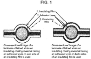
- the present inventors examined characteristics that allow characteristics necessary for obtaining an insulating coating material and/or an insulating film having excellent abrasion resistance to be confirmed using a method simpler than the conventional method, and discovered that, when an abrasion property is measured using the above method, a laminate of the structure of Fig. 1 can be prepared and used in the evaluation and thus, without the need of using a complicated process, a film having excellent abrasion resistance can be appropriately and efficiently obtained. That is, the present inventors found a correlation between abrasion resistance that is actually evaluated and a result of an abrasion property when a laminate of the structure of Fig. 1 is used.
- the present inventors prepared a large number of various films including an Apical film manufactured by Kaneka and a Kapton film manufactured by DuPont, which are already known as insulating films that are used in conventional insulating coating materials, and a film that is specifically disclosed in Patent Document 1 and has excellent dynamic cut resistance, and obtained insulating coating materials using the films, and performed various measurements of abrasion resistance of an insulated wire obtained by actually winding an insulating coating material on a wire and an abrasion property using the above-described laminate, and found that, when an insulating film or an insulating coating material is thin, in order for the abrasion resistance of an obtained insulated wire to be 200 times or more, the abrasion property obtained using the evaluation method in which the laminate of the present embodiment is used is at least 3.0 times or more.
- the present invention includes a method, which is a method for evaluating an abrasion property of an insulating coating material, in which the abrasion property is evaluated using a laminate obtained by laminating insulating films, adhesion layers and a conducting wire in the following order (a) or (b):
- An evaluation method of the abrasion property is not particularly limited. However, for example, a process can be adopted in which the above-described laminate is used in an evaluation method described in the British Standard Aerospace Series BS EN3475-503.
- the term "abrasion property evaluation” is synonymous with "abrasion property measurement", “abrasion resistance evaluation” or "abrasion resistance measurement.”
- a method described in Examples can be used.
- abrasion resistance of 100 times as a required physical property is described. This standard is referenced as a guide for abrasion resistance by aircraft manufacturers. Abrasion resistance of each of many insulating coating materials that are currently actually used for civil aircrafts and the like also depends on a thickness of the material. For a thin material, abrasion resistance of 100 times is used as a guide and the material is designed to have abrasion resistance larger than 100 times. However, in the present embodiment, in order to provide an insulating coating material having a higher degree of abrasion resistance, acceptable abrasion resistance is 300 times or higher.
- the abrasion resistance of an insulating coating material largely depends on characteristics of an insulating film and becomes worse as the insulating film becomes thinner.
- abrasion resistance of a resulting insulated cable is improved.
- a laminate is produced using a method described in the present specification and an abrasion property is 3.0 times or more.
- the abrasion property is preferably 3.5 times or more, more preferably 4.0 times or more, and particularly preferably 4.5 times or more.
- a value of the abrasion property is preferably as large as possible and an upper limit is not particularly set. However, for example, a value of 1000 times can be used as the upper limit.
- the laminate used in the evaluation has a structure as illustrated in Fig. 1 and is completely different both in structure and in production method from a long wire obtained by winding a long tape on a conducting wire and applying heat and pressure thereto.
- an insulating film may be used such that a measured abrasion property is 3.0 times or more.
- the adhesion layer is not particularly limited as long as the adhesion layer exhibits adhesiveness during the integration. However, from a point of view of capable of imparting an insulating property, it is preferable that a fluorine resin be used for the adhesion layer.
- An insulating film that can be used for the insulating coating material of the present embodiment is not particularly limited, and films formed from various insulating materials can be used.
- the insulating materials include polyurethane resin, poly (meth) acrylic resin, polyvinyl resin, polystyrene resin, polyethylene resin, polypropylene resin, polyimide resin, polyamide resin, polyacetal resin, polycarbonate resin, polyester resin, polyphenylene ether resin, polyphenylene sulfide resin, polyether sulfone resin, polyetheretherketone resin and the like. These materials can each be used alone, or two or more of these materials can be used in combination. Among these materials, a polyimide film using the polyimide resin is particularly preferable considering various characteristics such as heat resistance, electrical insulation, chemical resistance and flame resistance.
- the polyimide film is manufactured using polyamic acid as a precursor (hereinafter, the term "polyamic acid” is used synonymously with “polyimide precursor” in this specification).
- a method for manufacturing the polyamic acid is not particularly limited, and any commonly known method can be used.
- the polyamic acid can be manufactured by dissolving an acid dianhydride component and a diamine component in substantially equimolar amounts in an organic solvent and stirring the mixture under a controlled temperature condition until polymerization of the acid dianhydride component and the diamine component is completed.
- the polyamic acid is usually obtained at a concentration of 5 wt% (percent by weight) - 35 wt% and preferably 10 wt% - 30 wt%. When the concentration is in this range, appropriate molecular weight and viscosity are obtained.
- a polymerization method of the acid dianhydride component and the diamine component is not particularly limited, and any one of commonly known methods and any combination thereof can be used.
- One of characteristics of the polymerization method for the polymerization of the polyamic acid is an order of adding monomers, and various physical properties of resulting polyimide can be controlled by adjusting the order of adding the monomers.
- a method for adding the monomers for the polymerization of the polyamic acid is not particularly limited and any method may be used.
- examples of typical polymerization methods include the following methods.
- a method for obtaining a polyimide resin uses a method in which, first, a block component of a polyimide precursor is formed and thereafter a final polyimide precursor is formed using remaining diamine component and/or acid dianhydride component.
- the above methods 1) - 5) be used in partial combination.
- Example of a diamine component that can be used as a main component include 4,4'-diaminodiphenylpropane, 4,4'-diaminodiphenylmethane, 4,4'-diaminodiphenyl sulfide, 3,3'-diaminodiphenyl sulfone, 4,4'-diaminodiphenyl sulfone, 4,4'-oxydianiline, 3,3'-oxydianiline, 3,4'-oxydianiline, 4,4'-diaminodiphenyldiethylsilane, 4,4'-diaminodiphenylsilane, 4,4'-diaminodiphenylethylphosphine oxide, 4,4'-diaminodiphenyl N-methylamine, 4,4'-diaminodiphenyl N-phenylamine, 1,4-diaminobenzene (para-phenylenediamine (
- any diamine component can be used as an accessory component.
- examples of a diamine component that can be particularly preferably used include 4,4'-oxydianiline, 1,3-bis(4-aminophenoxy) benzene, 3,4'-oxydianiline, 1,4-diaminobenzene (p-phenylenediamine), and 2,2-bis[4-(4-aminophenoxy) phenyl] propane.
- Examples that can each be preferably used as an acid dianhydride component include pyromellitic acid dianhydride, 2,3,6,7-naphthalenetetracarboxylic acid dianhydride, 3,3',4,4'-benzophenonetetracarboxylic acid dianhydride, 2,2',3,3'-biphenyltetracarboxylic acid dianhydride, 3,3',4,4'-biphenyltetracarboxylic acid dianhydride, 2,2-bis(3,4-dicarboxyphenyl) propanoic acid dianhydride, p-phenylene bis(trimellitic acid monoester acid anhydride), 4,4'-oxydiphthalic acid dianhydride, and the like.
- acid dianhydride components selected from pyromellitic acid dianhydride, 3,3',4,4'-benzophenone tetracarboxylic acid dianhydride and 3,3',4,4'-biphenyltetracarboxylic acid dianhydride be used.
- a preferred solvent for synthesizing the polyamic acid is not particularly limited, and any solvent capable of dissolving the polyamic acid can be used.
- amide-based solvents that is, N,N-dimethylformamide (DMF), N,N-dimethylacetamide, N-methyl-2-pyrrolidone and the like, can be adopted.
- N,N-dimethylformamide and N,N-dimethylacetamide can be particularly preferably used.
- a filler can be added to the polyimide film for a purpose of improving various properties of the film such as slidability, thermal conductivity, electrical conductivity, corona resistance, loop stiffness and the like.
- Any filler may be used. However, preferred examples thereof include silica, titanium oxide, alumina, silicon nitride, boron nitride, calcium hydrogen phosphate, calcium phosphate, mica and the like.
- a method for manufacturing the polyimide film from a polyamic acid solution is not particularly limited, and various methods can be used. For example, a thermal imidization method and a chemical imidization method can be adopted, and a film can be manufactured using any one of the methods.
- processes for manufacturing a particularly preferred polyimide film include:
- a curing agent may be used that includes a dehydrating agent represented by an acid anhydride such as acetic anhydride, and an imidization catalyst represented by tertiary amines such as isoquinoline, quinoline, ⁇ -picoline, pyridine, diethylpyridine, and the like. Further, the dehydrating agent and the imidization catalyst can each be used alone.
- an insulating film can be selected by preparing a test specimen in which a conducting wire is sandwiched by an insulating coating material and an abrasion property thereof is evaluated such that the abrasion property is 3.0 times or more.
- the above-described abrasion property can be adjusted to become 3.0 times or more by selecting a monomer having a structure of a biphenyl skeleton as a polymerization component, by peeling off a gel film from a support and then stretching the gel film, or by selecting appropriate conditions such as setting a higher heating temperature in a process in which a gel film is peeled off from a support and thereafter is further heated to imidize remaining amic acid and to be dried.
- the above-described methods are merely examples.
- the methods may each be applied alone, or may be applied in combination of two or more thereof.
- Methods for obtaining an insulating film that satisfies the above two characteristics are not limited to the above-described methods.
- diamine component and acid dianhydride component it is more preferable to include ODA and PDA as the diamine component, and PMDA, BPDA and BTDA as the acid dianhydride component.
- the polymerization method is preferably a sequence polymerization method that includes steps of a first stage and a second stage.
- a "flexible chemical structure" segment be formed.
- at least ODA be used as a diamine component that forms the "flexible chemical structure” segment.
- at least BTDA be used as an acid dianhydride component.
- BTDA be contained at 10 mol% - 30 mol%.
- a monomer capable of forming a "rigid chemical structure" segment be used.
- PDA, PMDA or BPDA can be used as a monomer capable of forming a "rigid chemical structure" segment.
- PDA and PMDA be used as main components.
- the diamine component of the entire polyimide 40 mol% - 60 mol% be PDA.
- the acid dianhydride component of the entire polyimide 45 mol% - 85 mol% be PMDA.
- the acid dianhydride component of the entire polyimide 15 mol% - 25 mol% be BPDA.
- the thickness of the insulating film is not particularly limited. However, in order to realize weight reduction, for example, the thickness of the insulating film is preferably 20 ⁇ m or less, and more preferably 18 ⁇ m or less. According to the present invention, even for an insulating film that has been reduced in thickness in this way, it is possible to provide an insulating film and an insulating coating material that have excellent abrasion resistance.
- a lower limit of the thickness of the insulating film is not particularly limited. However, for example, the thickness of the insulating film is preferably 5 ⁇ m or more.
- An adhesion layer that can be used for the insulating coating material of the present embodiment is not particularly limited, and various adhesion layers can be used.
- any material may be used as long as the material can bond an insulating film to a conductor of an electric wire or a conducting wire such as a cable (wire).
- a thermoplastic resin it is preferable that a thermoplastic resin be used.
- thermoplastic resins from a point of view of an insulating property, chemical resistance and the like, it is preferable that a fluorine resin be used.
- a tetrafluoroethylene polymer for example, a tetrafluoroethylene polymer, a tetrafluoroethylene-hexafluoropropylene copolymer (FEP), a tetrafluoroethylene and perfluoro (alkyl vinyl ether) copolymer, a tetrafluoroethylene-ethylene copolymer, polychlorotrifluoroethylene, an ethylene-chlorotrifluoroethylene copolymer, polyvinylidene fluoride, a vinylidene fluoride and hexafluoropropylene copolymer, polyvinyl fluoride and the like can each be used alone or can be used in combination of two or more thereof.
- FEP tetrafluoroethylene-hexafluoropropylene copolymer
- tetrafluoroethylene polymer or tetrafluoroethylene and perfluoro (alkyl vinyl ether) copolymer be used. From a point of view of having a low melting point and allowing pressure bonding to be performed at a relatively low temperature and allowing a laminate to be easily and reliably obtained, it is more preferable that FEP be used.
- An adhesion layer may be provided as a dispersion applied on an insulating film and may also be provided by using a film as an adhesion layer.
- a thickness of the adhesion layer is not particularly limited as long as adhesiveness is developed. However, it is preferable that the thickness of the adhesion layer be 0.5-13 ⁇ m.
- At least one adhesion layer is formed on the insulating film. That is, the insulating coating material may have a two-layer structure. Further, it is also possible that the adhesion layer is formed on both surfaces of the insulating film. That is, the insulating coating material may have a three-layer structure. Further, it is also possible that multiple adhesion layers are formed on one side of the insulating film. Further, it is also possible that one adhesion layer is formed on one side of the insulating film and multiple adhesion layers are formed on the other side of the insulating film. Further, it is also possible that multiple adhesion layers are formed on both sides of the insulating film. That is, for example, the insulating coating material according to the present embodiment can be manufactured by covering one side or both sides of an insulating film such as polyimide film that functions as a base layer with an adhesion layer containing a fluorine resin.
- an insulating film such as polyimide film that functions as a base layer with an adhesion layer
- the insulating coating material according to the present embodiment has an adhesion layer on at least one side of an insulating film, and is obtained by heating and firing after laminating such an adhesion layer.
- the laminate of the insulating film and the adhesion layer can be manufactured by a person skilled in the art using any commonly known method. However, for example, the laminate can be usually obtained using a method in which a film-like adhesion layer is laminated on an insulating film or a method in which a resin dispersion of an adhesion layer is applied to an insulating film.
- the adhesion layer used in the present invention is a fluorine resin
- the dispersion for example, a dispersion obtained by dispersing a tetrafluoroethylene-hexafluoropropylene copolymer (FEP), a tetrafluoroethylene and perfluoro (alkyl vinyl ether) copolymer (PFA), polytetrafluoroethylene (PTFE), or the like, in water or in an organic solvent can be used.
- FEP tetrafluoroethylene-hexafluoropropylene copolymer
- PFA tetrafluoroethylene and perfluoro (alkyl vinyl ether) copolymer
- PTFE polytetrafluoroethylene
- a solid state component concentration of the dispersion used here is not particularly limited.
- a solid state component concentration of 10 wt% - 70 wt% is preferable in terms of handling.
- Typical examples of the film in the case of laminating include films of a tetrafluoroethylene-hexafluoropropylene copolymer, polytetrafluoroethylene, a tetrafluoroethylene-perfluoroalkyl vinyl ether copolymer, a tetrafluoroethylene-ethylene copolymer, polychlorotrifluoroethylene containing chlorine, and the like.
- the dispersion can be applied several times until a thickness of the fluorine resin used for the laminate of the polyimide and the fluorine resin according to the present embodiment reaches an appropriate thickness.
- An inorganic or organic filler or the like may be added to the dispersion or the film using a commonly known method. Further, a surface of the fluorine resin or a bonding surface of the fluorine resin to the polyimide film may be subjected to a commonly known surface treatment such as a corona discharge treatment or a plasma discharge treatment.
- the insulating coating material thus obtained is wound on a conducting wire, and the resulting wire is used as an insulated wire (insulated cable).
- the present invention can include an insulated cable (wire) with the above insulating coating material.
- an insulated cable for example, can be suitably used for a conducting wire such as an electric wire or a cable (wire) for aerospace applications such as aircrafts and the like.
- the conducting wire such as an electric wire or a cable (wire) can use any material as long as the material is a conductor.
- a metal is usually used. Examples of the metal include copper, aluminum, stainless steel and the like. Although copper is preferred, aluminum is also preferred from the point of view of weight reduction. Further, these metals may be various alloys, and their surfaces may be plated with various materials.
- a method for manufacturing the insulated cable is not particularly limited, and various methods can be used.
- the insulated cable can be manufactured by forming the insulating coating material into a tape (long object) and spirally winding such a tape of the insulating coating material around a conductor (such as a metal). Further, it is also possible that, after the tape of the insulating coating material is wound around the conductor once, a tape of another insulating coating material is further wound around the conductor in an overlapping manner.
- a tensional force applied to the tape can be widely varied from a tensional force enough to avoid occurrence of wrinkling to a range of a tensional force strong enough to pull the tape to cause neck down to occur. Even when the tensional force is small, due to an influence of heat (for example, heating to 240 °C - 500 °C) in a heat sealing process that is performed after the winding, the tape shrinks and thus, the conductor is covered with good adhesion by the insulating coating material.
- heat for example, heating to 240 °C - 500 °C
- the heat sealing process can be appropriately set according to the thickness of the insulating film, the thickness of the adhesion layer, the material of the conductor, a speed of a production line, a length of a seal oven, and the like. Further, the winding of the insulating coating material on the conductor can also be performed using a standard electric wire coating machine (wrapping machine) or the like.
- Embodiment (B) only portions that are different from Embodiment (A) are described, and for other portions, Embodiment (A) is incorporated.
- An insulating coating material includes an insulating film and an adhesion layer.
- yield strength obtained from a stress-strain curve which is obtained by tensile elastic modulus measurement, is 160 MPa or more and a stress (x) (MPa) and a strain (a) (%) in a plastic deformation region satisfy the following Formula (1).
- the present inventors found that, conventionally, in order to evaluate abrasion resistance of an insulating coating material, it is necessary to prepare a long insulating coating material that includes an insulating film and an adhesion layer and has a width of about 6 mm and to prepare an insulated wire by winding the insulating coating material around a conducting wire; evaluation of the insulated wire is itself very complicated, and it is difficult for an evaluation result of the insulated wire to be reflected in a design of an insulating film or in an insulating coating material using the insulating film; when an abrasion property is evaluated using a laminate, which is obtained by integrating members by laminating the members and applying heat and pressure thereto such that the laminate has a structure of insulating coating material/conducting wire/insulating coating material, for a larger value of the abrasion property, an insulating coating material having a more excellent abrasion resistance can be provided.
- the present inventors found that, when an insulating coating material is designed by focusing on properties of an insulating film, with respect to a laminate, which is obtained by integrating members by laminating the members and applying heat and pressure thereto such that the laminate has a structure of insulating film/adhesion layer/conducting wire/adhesion layer/insulating film, when an abrasion property is evaluated, and when an insulating film is used such that the value of the abrasion property is increased, the insulating coating material has excellent abrasion resistance.
- Conditions for producing the laminate for the abrasion property evaluation are not particularly limited. However, the heating temperature may be in a range of 280 - 340 °C, the pressure may be in a range of 35 - 90 kgf/cm 2 , and the heating time may be in a range of 5 - 20 minutes.
- AMG high performance conductor nickel coated copper
- CONST 19/32, diameter: 0.9 mm
- the adhesion layer that is used in the case where the insulating coating material is designed by focusing on the properties of the insulating film is not particularly limited as long as the adhesion layer exhibits adhesiveness during the integration. However, from a point of view of capable of imparting an insulating property, it is preferable that a fluorine resin be used for the adhesion layer.
- PTFE polytetrafluoroethylene
- PFA tetrafluoroethylene-perfluoroalkyl vinyl ether copolymer
- FEP tetrafluoroethylene-hexafluoropropylene copolymer
- the adhesion layer may be provided by applying a dispersion or may be provided by using a film.
- a thickness of the film is not particularly limited. However, from a point of view of transportability during processing, it is particularly preferable that a film having a thickness of 12 ⁇ m be used.
- the abrasion property can be evaluated according to a device and a protocol described in the British Standard Aerospace Series BS EN3475-503.
- a FEP film having a thickness of 12 ⁇ m can be used.
- the present inventors examined improvement for the abrasion property at 23 °C with respect to various insulating films, and found that, when the abrasion property exceeds 2.0 times, the abrasion resistance can reach about 200 times; when the abrasion property exceeds 3.0 times, the abrasion resistance can reach about 300 times; when the abrasion property exceeds 4.0 times, the abrasion resistance can reach about 400 times; and when the abrasion property exceeds 5.0 times, the abrasion resistance can reach about 500 times.
- the abrasion property is preferably 2.0 times or more, more preferably 3.0 times or more, even more preferably 4.0 times or more, and particularly preferably 5.0 or more.
- the British Standard Aerospace Series BS EN3475-503 is a standard that is referenced as a guide for abrasion resistance by aircraft manufacturers.
- Abrasion resistance of each of many insulating coating materials that are currently actually used for civil aircrafts and the like also depends on a thickness of the material.
- an abrasion resistance of 100 times is used as a guide and the material is designed to have an abrasion resistance larger than 100 times. Therefore, even when the abrasion property increases by only 0.5 times, a significant effect can be obtained in the abrasion resistance.
- a material having an abrasion property of 2.0 times or more (abrasion resistance of about 200 times or more) is preferable.
- the present inventors further advanced the study and examined what kind of an insulating film is to be used in order to provide an insulating coating material having excellent abrasion resistance, that is, an insulating coating material having a good abrasion property.
- a film having an excellent abrasion property leads to an insulating coating material in which an insulating film, which has a high yield strength in a stress-strain curve obtained by tensile elastic modulus measurement and in which a stress increases even in a plastic deformation region, has an excellent abrasion property.
- an insulating film used for the insulating coating material of the present embodiment is described in detail.
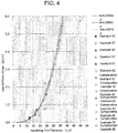
- the yield strength obtained from a stress-strain curve which is obtained by tensile elastic modulus measurement, is 160 MPa or more and a stress (x) (MPa) and a strain (a) (%) in a plastic deformation region satisfy the following Formula (1). 2.6 ⁇ a + 175 ⁇ x ⁇ 6.0 ⁇ a + 370
- a strain mode that is, in a tension mode
- the rise in the stress is steep from the beginning of pulling the film, and the yield strength is also large, and further, the stress increases even after passing a yield point and entering a plastic deformation region.
- an insulating film of which an absolute value of yield strength obtained using a stress-strain curve is large and a stress increases in a plastic deformation region, imparts excellent abrasion property to an insulating coating material.
- the stress-strain curve can be obtained by performing tensile elastic modulus measurement according to ASTM D882.
- the yield strength can be considered as a stress at an inflection point that first appears in the stress-strain curve.
- the yield strength is obtained as follows. First, a slope of a tangent at a strain of 1 % is obtained. Next, sequentially, for every 0.5% increase in strain, a slope of a tangent at that strain (such as a slope of a tangent at a strain of 1.5%, and a slope of a tangent at a strain of 2%) is obtained. Then, a stress at a point where slope reaches 14 MPa/% is read. The slope of 14 MPa/% is obtained from a stress curve where an inflection point appears most clearly in an experimental example.
- the yield strength in the present invention is 160 MPa or more. This is obtained as yield strength that is considered necessary to impart an excellent abrasion property to an insulating coating material, which does not include a conventionally commercially available insulating film for an insulating coating material or an insulating film disclosed in the prior art in the technical field of insulating coating materials. Higher yield strength is preferable.
- the yield strength is more preferably 175 MPa or more, further preferably 200 MPa or more, and particularly preferably 230 MPa or more.
- the stress (x) (MPa) in the plastic deformation region can be expressed using a relational formula with the strain (a) (%), and satisfies the following Relational Formula (1). 2.6 ⁇ a + 175 ⁇ x ⁇ 6.0 ⁇ a + 370
- the plastic deformation region is defined as follows. In the stress-strain curve, the slope of the tangent at the strain of 1% is obtained. Next, sequentially, a slope of a tangent is obtained for every 1% increase in strain. In this way, the slopes are obtained and a point where a difference between the slope at the strain of n% and the slope at the strain of (n + 1)% reaches 1 Mpa/% or less is obtained. In this case, a region from the point of the strain of n% to a point where breaking occurs is defined as the plastic deformation region, and whether or not the stress (x) in this region satisfies Formula (1) is determined.
- the insulating film used in the present invention exhibits a behavior that the stress (x) increases in the plastic deformation region.
- the stress (x) decreases slightly just before breaking and falls outside the range specified by Formula (1), the effect of the present invention is considered to be still present. Therefore, the slight decrease in the strain (x) just before breaking may be ignored.
- the stress (x) in the plastic deformation region of the insulating film of the present embodiment exceeds 2.6 ⁇ a + 175 (where "x" represents the stress (MPa) and "a” represents the strain (%)).
- the stress (x) in the plastic deformation region increases with a slope of at least 2.6 MPa/% with respect to the strain, and needs to be in a range larger than the above linear function with an intercept of 175. It is not preferable for the stress (x) to be below this range, because the abrasion property would deteriorate.
- the stress (x) of the insulating film of the present embodiment be as large as possible.
- the stress (x) increases with a slope of 6.0 MPa/% and be in a range smaller than a linear function with an intercept of 370.
- the stress (x) satisfy the following Formula (2), further preferable that the stress (x) satisfy the following Formula (3), and particularly preferable that the stress (x) satisfy the following Formula (4).
- 2.7 ⁇ a + 195 ⁇ x ⁇ 6.0 ⁇ a + 370 2.8 ⁇ a + 215 ⁇ x ⁇ 6.0 ⁇ a + 370 3.7 ⁇ a + 260 ⁇ x ⁇ 6.0 ⁇ a + 370
- An insulating film that can be used for the insulating coating material of the present embodiment is not particularly limited, and films formed from various insulating materials can be used.
- hydrolysis resistance may be required together with the abrasion resistance for the insulating film.
- the hydrolysis resistance for example, can be evaluated using tear strength retention rates before and after a PCT test (pressure cooker test). Tear strength can be evaluated before and after a PCT test according to ASTM D-1938. For example, a PCT test was conducted for 96 hours under conditions of 150 °C, 100% RH, 0.4 MPa. A value obtained by dividing tearing strength after a PCT test by tearing strength before the PCT test can be used as a tear strength PCT retention rate.
- an insulating film can be selected by preparing a test specimen in which a conducting wire is sandwiched by an insulating coating material and an abrasion property thereof is evaluated such that the abrasion property is 2.0 times or more.
- the above-described abrasion property can be adjusted to become 2.0 times or more by selecting a monomer having a structure of a biphenyl skeleton as a polymerization component, by peeling off a gel film from a support and then stretching the gel film, or by selecting appropriate conditions such as setting a higher heating temperature in a process in which a gel film is peeled off from a support and thereafter is further heated to imidize remaining amic acid and to be dried.
- examples of preferred methods for obtaining an insulating film satisfying the above characteristics include the following method.
- the thickness of the insulating film is not particularly limited. However, in order to realize weight reduction, for example, the thickness of the insulating film is preferably 25 ⁇ m or less, more preferably 20 ⁇ m or less, and particularly preferably 18 ⁇ m or less. According to the present invention, even for an insulating film that has been reduced in thickness in this way, it is possible to provide an insulating film and an insulating coating material that have excellent abrasion resistance.
- a lower limit of the thickness of the insulating film is not particularly limited. However, for example, the thickness of the insulating film is preferably 5 ⁇ m or more.
- Embodiment (A) is incorporated.
- the insulating coating material according to the present embodiment is obtained by laminating an adhesion layer on both sides or one side of an insulating film and by heating and firing after laminating such an adhesion layer.
- a thickness of the fluorine resin used for the laminate of the polyimide and the fluorine resin according to the present invention reaches an appropriate thickness.
- a film thickness of the film of the fluorine resin is preferably 7.5 - 25 ⁇ m.
- Embodiment (A) is incorporated.
- Embodiment (C) only portions that are different from Embodiments (A) and (B) are described, and for other portions, Embodiments (A) and (B) are incorporated.
- An insulating coating material according to the present embodiment has an adhesion layer on at least one side of an insulating film.
- k is 0.000105 or more.
- the loop stiffness value (a) (g/cm) is a value actually measured using a loop stiffness tester and, for example, can be measured using a loop stiffness tester manufactured by Toyo Seiki Seisaku-sho Ltd.
- the loop stiffness value (a) (g/cm) is a value obtained by reading a force when two minutes have elapsed after squashing under conditions that a sample width is 10 mm, a loop length is 50 mm, and a distance between squashings is 10 mm for the measurement.
- the thickness ( ⁇ m) of the insulating film can be measured using a contact thickness gauge.
- the present inventors found that, conventionally, in order to evaluate abrasion resistance of an insulating coating material, it is necessary to prepare a long insulating coating material that includes an insulating film and an adhesion layer and has a width of about 6 mm and to prepare an insulated wire by winding the insulating coating material around a conducting wire; evaluation of the insulated wire is itself very complicated, and it is difficult for an evaluation result of the insulated wire to be reflected in a design of an insulating film or in an insulating coating material using the insulating film; when an abrasion property is evaluated using a laminate, which is obtained by integrating members by laminating the members and applying heat and pressure thereto such that the laminate has a structure of insulating coating material/conducting wire/insulating coating material, for a larger value of the abrasion property, an insulating coating material having a more excellent abrasion resistance can be provided.
- the present inventors found that, when an insulating coating material is designed by focusing on properties of an insulating film, with respect to a laminate, which is obtained by integrating members by laminating the members and applying heat and pressure thereto such that the laminate has a structure of insulating film/adhesion layer/conducting wire/adhesion layer/insulating film, when an abrasion property is evaluated, and when an insulating film is used such that the value of the abrasion property is increased, the insulating coating material has excellent abrasion resistance.
- Conditions for producing the laminate for the abrasion property evaluation are not particularly limited.
- the heating temperature may be in a range of 280 - 340 °C
- the pressure may be in a range of 35 - 90 kgf/cm 2
- the heating time may be in a range of 5 - 20 minutes.
- the abrasion property is evaluated according to a device and a protocol described in the British Standard Aerospace Series BS EN3475-503.
- an insulating coating material having excellent abrasion resistance that is, an insulating coating material having a good abrasion property
- an insulating film having excellent abrasion resistance leads to an insulating coating material in which an insulating film of which a loop stiffness value and a thickness satisfy Formula (1) has an excellent abrasion property.
- Patent Document 4 suggests that a loop stiffness value is proportional to an elastic modulus of a film and is proportional to the cube of a thickness of the film. However, this indicates only a certain kind of tendency. Even in Patent Document 4, it is clear from the description and the examples that the loop stiffness value means only a measured value.
- the loop stiffness value used in the present invention refers to a measured value that is measured using a loop stiffness tester.
- the elastic modulus is one of film properties that are frequently measured by a person skilled in the art in the technical field as described in Patent Document 4.
- the present inventors found that the elastic modulus does not provide guidance for the design of the insulating film that leads to an insulating coating material having excellent abrasion resistance. That is, an insulating film having a high elastic modulus does not necessarily lead to an insulating coating material having excellent abrasion resistance.
- the present inventors prepared insulating films that exhibit different loop stiffness values by focusing on loop stiffness values that are not often measured in the field of insulating films used for insulating coating materials for covering electric wires and cables and by intensively examining types and composition ratios of monomers used as raw materials for the insulating films and manufacturing conditions and the like for film formation, stretching and the like.
- the present inventors found that an insulating film having a specific loop stiffness value is an insulating film that leads to an insulating coating material having excellent abrasion resistance, and thus accomplished the present invention.
- the insulating coating material of the present embodiment is a film different from those conventional insulating films that have been used, and is a novel insulating coating material using the insulating film.
- the insulating film used for the insulating coating material of the present embodiment solves the problem by having k being 0.000105 or more in Formula (1). However, it is more preferable that k be 0.000113 or more, and even more preferable that k be 0.000120.
- the loop stiffness value be as high as possible. However, from a point of view of suppressing spring back when the insulating coating material is wound around a conducting wire, it is more preferable that the loop stiffness value be 2.4 g/cm or less, and even more preferable that the loop stiffness value be 1.6 g/cm or less, and particularly preferable that the loop stiffness value be 1.0 g/cm or less.
- the insulating coating material according to the present embodiment has an excellent abrasion resistance as compared to a conventional insulating coating material not only when the film is thick but also when the film is thin.
- the thickness of the insulating film is not particularly limited.
- the thickness of the insulating film is preferably 25 ⁇ m or less, more preferably 20 ⁇ m or less, even more preferably 18 ⁇ m or less, and particularly preferably 17 ⁇ m or less. According to the present invention, even for an insulating film that has been reduced in thickness in this way, it is possible to provide an insulating film and an insulating coating material that have excellent abrasion resistance.
- a lower limit of the thickness of the insulating film is not particularly limited. However, for example, the thickness of the insulating film is preferably 5 ⁇ m or more.
- an insulating coating material by combining an insulating film having such characteristics with an adhesion layer (to be described later), preferably an adhesion layer containing a fluorine resin, abrasion resistance of an insulated wire obtained by winding the insulating coating material on a conducting wire or the like is significantly improved.
- An insulating coating material includes an insulating film and an adhesion layer.
- k is 0.000105 or more.
- a k ⁇ ⁇ b 3 (In Formula (1), "a" represents the loop stiffness value (g/cm), and “b” represents the thickness ( ⁇ m) of the insulating film).
- a method for adding monomers for polymerization of the polyamic acid is not particularly limited, and any method may be used. However, for example, the method described in the above in Embodiment (A) can be preferably used.
- the loop stiffness value can be easily measured. Therefore, it is possible to select the monomer and the polymerization method such that a desired loop stiffness value is obtained. There is a tendency that the loop stiffness value increases as the number of rigid chemical structures increases and decreases as the number of flexible chemical structures increases. Therefore, the adjustment of the loop stiffness value can be performed by adjusting a ratio of a component having a rigid structure to a component having a flexible structure in the acid dianhydride component and the diamine component.
- a method combined with the method 3) or 4) allows a unit having a flexible structure or a unit having a rigid structure to be selectively introduced with a desired unit length and thus is suitable for adjusting the loop stiffness value.
- Embodiments (A) and (B) are incorporated.
- hydrolysis resistance may be required together with the abrasion resistance for the insulating film.
- the hydrolysis resistance according to the present embodiment was evaluated using tear strength retention rates before and after a PCT test (pressure cooker test). The tear strength was measured before and after a PCT test according to ASTM D-1938. The PCT test was conducted for 96 hours under conditions of 150 °C, 100% RH, 0.4 MPa. A value obtained by dividing the tearing strength after the PCT test by the tearing strength before the PCT test was used as a tear strength PCT retention rate.
- a preferred method for obtaining an insulating film satisfying the tear strength PCT retention rate is the same as the method suitable for adjusting the loop stiffness value.
- a filler can be added to the polyimide film for a purpose of improving various properties of the film such as slidability, thermal conductivity, electrical conductivity, corona resistance, a loop stiffness value and the like.
- processes for manufacturing a particularly preferred polyimide film include:
- the loop stiffness value can be adjusted by adjusting a tensional force acting on the gel film after peeling off the gel film in the process iii). There is a tendency that the loop stiffness value increases when the tensional force acting on the gel film increases.
- a curing agent may be used that includes a dehydrating agent represented by an acid anhydride such as acetic anhydride, and an imidization catalyst represented by tertiary amines such as isoquinoline, quinoline, ⁇ -picoline, pyridine, diethylpyridine, and the like. Further, the dehydrating agent and the imidization catalyst can each be used alone.
- the loop stiffness value is set to a desired range by using these methods independently or in combination.
- an insulating film is obtained by physically removing the adhesion layer, such as scraping a surface of the insulating coating material, and a loop stiffness value of the insulating film is measured.
- Embodiment (A) is incorporated.
- the insulating coating material according to the present embodiment is obtained by laminating an adhesion layer on both sides or one side of an insulating film and by heating and firing after laminating such an adhesion layer.
- Embodiment (A) is incorporated.
- Embodiments (A) - (C) are appropriately combined is also an example of an embodiment of the present invention.
- Examples of forms in which Embodiments (A) - (C) are combined include, specifically, the following combinations.
- the present invention has the following structures.
- a polyimide precursor was prepared using 40 mol% of 3,3',4,4'-biphenyltetracarboxylic acid dianhydride, 60 mol% of pyromellitic acid dianhydride, 60 mol% para-phenylenediamine and 40 mol% of 4,4'diaminodiphenyl ether described in Example (1A) of Patent Document 1.
- the polyimide precursor (1A) (110 g) obtained in Synthesis Example (1A) contained the following chemical dehydrating agent and catalyst and DMF.
- the mixture was stirred and defoamed at a temperature of 0 °C or less, and was applied by casting on an aluminum foil using a comma coater.
- This resin film was heated at 118 °C for 110 seconds. Thereafter a self-supporting gel film was peeled off from the aluminum foil and was fixed to a metal frame, and was dried and imidized at 250 °C for 15 seconds, at 350 °C for 15 seconds, and at 450 °C for 110 seconds, and a polyimide film having a thickness of 18 ⁇ m was obtained.
- the polyimide precursor obtained in Synthesis Example (1A) contained the following chemical dehydrating agent and catalyst and DMF.
- the polyimide precursor containing the chemical dehydrating agent and the catalyst and the DMF was continuously extruded from a multi-manifold die having a lip width of 520 mm cooled to about 0 °C, and was cast on an endless belt made of SUS running 50 mm below the die. After the casting, heating was performed for 110 seconds stepwise in a temperature range of 50 °C - 140 °C, and a gel film that had developed a self-supporting property was peeled off from the SUS endless belt. The peeled gel film was fixed to a pin sheet and was dried and imidized stepwise in a temperature range of 250 °C - 400 °C. The obtained polyimide film had a thickness of 18 ⁇ m.
- An FEP (tetrafluoroethylene-hexafluoropropylene copolymer) aqueous dispersion was applied on both sides of the obtained polyimide film such that an FEP layer on each side of the polyimide film had a thickness of 2 ⁇ m.
- the resulting structure was dried at a temperature of 150 °C for 65 second and was fired at a temperature of 420 °C for 15 seconds, and thus an insulating coating material having a structure of FEP/polyimide/FEP and a total thickness of 22 ⁇ m was prepared.
- the obtained insulating coating material was slit into a tape shape to obtain a long tape-like insulating coating material.
- the obtained long tape-like insulating coating material was spirally wound around a 0.9 mm ⁇ conducting wire (high performance conductor nickel coated copper (AWG: 20, CONST: 19/32) manufactured by Phelps Dodge Corporation) to obtain a long wire.
- AMG high performance conductor nickel coated copper
- CONST 19/32 manufactured by Phelps Dodge Corporation
- Time required from when the chemical dehydrating agent and the catalyst and the DMF were contained in the polyimide precursor to when the long wire was obtained was 96 hours.
- measurement was performed five times according to British Standard Aerospace Series BS EN3475-503, and an average value thereof was used as the abrasion resistance.
- the Repeated Scrape Abrasion Tester (Cat 158L238G1), manufactured by WELLMAN Co., Ltd., was used. The result is shown in Table 1.
- a polyimide film was prepared in the same manner as in Example (1A).
- the obtained polyimide film had a thickness of 18 ⁇ m.
- An FEP (tetrafluoroethylene-hexafluoropropylene copolymer) aqueous dispersion was applied on one side of the obtained polyimide film such that an FEP layer on the one side of the polyimide film had a thickness of 2 ⁇ m.
- the resulting structure was dried at a temperature of 150 °C for 65 second and was fired at a temperature of 420 °C for 15 seconds, and thus an insulating coating material having a structure of FEP/polyimide was prepared.
- the laminate has a structure of insulating coating material/0.9 mm ⁇ conducting wire/insulating coating material in which the FEP (tetrafluoroethylene-hexafluoropropylene copolymer)surface of the insulating coating material is in contact with the conducting wire, by laminating members so as to have a structure of SUS plate /cushioning material/the above-described laminate/cushioning material/SUS plate and applying a pressure of 80 kgf/cm 2 at 305 °C for 20 minutes, a laminate was obtained.
- FEP tetrafluoroethylene-hexafluoropropylene copolymer
- a high performance conductor nickel coated copper (AWG: 20, CONST: 19/32, diameter: 0.9 mm) manufactured by Phelps Dodge Corporation was used.
- the abrasion property was evaluated in the same manner as in Example (1A). The result is shown in Table 1.
- a polyimide film was prepared in the same manner as in Example (1A).
- the obtained polyimide film had a thickness of 18 ⁇ m.
- An insulating coating material having a total thickness of 20 ⁇ m was obtained in the same manner as in Example (1 A) except that an FEP (tetrafluoroethylene-hexafluoropropylene copolymer) aqueous dispersion was applied on one side of the obtained polyimide film such that an FEP layer on the one side of the polyimide film had a thickness of 2 ⁇ m.
- an FEP tetrafluoroethylene-hexafluoropropylene copolymer
- a polyimide film was prepared in the same manner as in Example (1A).
- the obtained polyimide film had a thickness of 18 ⁇ m.
- a laminate was obtained in the same manner as in Example (2A) except that an FEP (tetrafluoroethylene-hexafluoropropylene copolymer) aqueous dispersion was applied on both sides of the obtained polyimide film such that an FEP layer on each side of the polyimide film had a thickness of 2 ⁇ m.
- Time required from when the chemical dehydrating agent and the catalyst and the DMF were contained in the polyimide precursor to when the laminate was obtained was 2.0 hours.
- the abrasion property was evaluated in the same manner as in Example (1A). The result is shown in Table 1.
- a polyimide film was prepared in the same manner as in Example (1A).
- the obtained polyimide film had a thickness of 18 ⁇ m.
- An insulating coating material having a total thickness of 22 ⁇ m was obtained in the same manner as in Example (2A) except that an FEP (tetrafluoroethylene-hexafluoropropylene copolymer) aqueous dispersion was applied on both sides of the obtained polyimide film such that an FEP layer on each side of the polyimide film had a thickness of 2 ⁇ m.
- an FEP tetrafluoroethylene-hexafluoropropylene copolymer
- a polyimide film was prepared in the same manner as in Example (1A) except that the polyimide precursor (2A) obtained in Synthesis Example (2A) was used.
- the obtained polyimide film had a thickness of 20 ⁇ m.
- a laminate was prepared in the same manner as in Example (1A). Time required from when the chemical dehydrating agent and the catalyst and the DMF were contained in the polyimide precursor to when the laminate was obtained was 0.9 hours. With respect to the obtained laminate, the abrasion property was evaluated in the same manner as in Example (1A). The result is shown in Table 1.
- a polyimide film was prepared in the same manner as in Example (1A) except that the polyimide precursor (2A) obtained in Synthesis Example (2A) was used.
- the obtained polyimide film had a thickness of 20 ⁇ m.
- an insulating coating material was obtained in the same manner as in Example (1A).
- a long wire was obtained in the same manner as in Example (1A). Time required from when the chemical dehydrating agent and the catalyst and the DMF were contained in the polyimide precursor to when the long wire was obtained was 96 hours. With respect to the obtained long wire, the abrasion resistance was evaluated in the same manner as in Example (1A). The result is shown in Table 1.
- Example (1A) As a polyimide film, an Apical AV (US product name (expressed as "Apical AH" in Japan)) having a thickness of 25 ⁇ m was used, and a laminate was obtained in the same manner as in Example (1A). Time required to obtain the laminate was 0.9 hours. With respect to the obtained laminate, the abrasion property was evaluated in the same manner as in Example (1A). The result is shown in Table 1.
- Example (1A) As a long polyimide film, an Apical AV having a thickness of 25 ⁇ m was used, and an insulating coating material having a structure of FEP/polyimide/FEP was prepared in the same manner as in Example (1A). Using the obtained insulating coating material, a long wire was obtained in the same manner as in Example (1A). Time required from a state of a film to when the long wire was obtained was 48 hours. With respect to the obtained long wire, the abrasion resistance was evaluated in the same manner as in Example (1A). The result is shown in Table 1.
- Example (1A) As a polyimide film, Kapton E having a thickness of 25 ⁇ m was used, and a laminate was obtained in the same manner as in Example (1A). Time required to obtain the laminate was 0.5 hours. With respect to the obtained laminate, the abrasion property was evaluated in the same manner as in Example (1A). The result is shown in Table 1.
- Example (1A) As a long polyimide film, Kapton E having a thickness of 25 ⁇ m was used, and an insulating coating material having a structure of FEP/polyimide/FEP was prepared in the same manner as in Example (1A). Using the obtained insulating coating material, a long wire was obtained in the same manner as in Example (1A). Time required from a state of a film to when the long wire was obtained was 48 hours. With respect to the obtained long wire, the abrasion resistance was evaluated in the same manner as in Example (1A). The result is shown in Table 1.
- Example (1A) As a polyimide film, an Apical AV having a thickness of 19 ⁇ m was used, and a laminate was obtained in the same manner as in Example (1A). Time required to obtain the laminate was 0.9 hours. With respect to the obtained laminate, the abrasion property was evaluated in the same manner as in Example (1A). The result is shown in Table 1.
- Example (1A) As a long polyimide film, an Apical AV having a thickness of 19 ⁇ m was used, and an insulating coating material having a structure of FEP/polyimide/FEP was prepared in the same manner as in Example (1A). Using the obtained insulating coating material, a long wire was obtained in the same manner as in Example (1A). Time required from a state of a film to when the long wire was obtained was 48 hours. With respect to the obtained long wire, the abrasion resistance was evaluated in the same manner as in Example (1A). The result is shown in Table 1.
- a polyimide film was prepared in the same manner as in Example (1A) except that the polyimide precursor (3A) obtained in Synthesis Example (3A) was used.
- the obtained polyimide film had a thickness of 19 ⁇ m.
- a laminate was prepared in the same manner as in Example (1A). Time required from when the chemical dehydrating agent and the catalyst and the DMF were contained in the polyimide precursor to when the laminate was obtained was 0.9 hours. With respect to the obtained laminate, the abrasion property was evaluated in the same manner as in Example (1A). The result is shown in Table 1.
- a polyimide film was prepared in the same manner as in Example (1A) except that the polyimide precursor (3A) obtained in Synthesis Example (3A) was used.
- the obtained polyimide film had a thickness of 18 ⁇ m.
- an insulating coating material was obtained in the same manner as in Example (1A).
- a long wire was obtained in the same manner as in Example (1A). Time required from when the chemical dehydrating agent and the catalyst and the DMF were contained in the polyimide precursor to when the long wire was obtained was 96 hours. With respect to the obtained long wire, the abrasion resistance was evaluated in the same manner as in Example (1A). The result is shown in Table 1.
- a polyimide film was prepared in the same manner as in Example (1A) except that the polyimide precursor (4A) obtained in Synthesis Example 4 was used and drying and imidization was performed at 120 °C for 150 seconds, at 250 °C for 18 seconds, at 350 °C for 18 seconds, and at 450 °C for 120 seconds.
- the obtained polyimide film had a thickness of 25 ⁇ m.
- a laminate was prepared in the same manner as in Example (1A). Time required from when the chemical dehydrating agent and the catalyst and the DMF were contained in the polyimide precursor to when the laminate was obtained was 0.9 hours. With respect to the obtained laminate, the abrasion resistance was evaluated in the same manner as in Example (1A). The result is shown in Table 1.
- a polyimide film was prepared in the same manner as in Example (1A) except that the polyimide precursor (4A) obtained in Synthesis Example 4 was used.
- the obtained polyimide film had a thickness of 25 ⁇ m.
- an insulating coating material was obtained in the same manner as in Example (1A).
- a long wire was obtained in the same manner as in Example (1A).
- Tensile elastic modulus measurement was performed according to ASTM D882.
- ASTM D882 An Autograph AGS-J manufactured by Shimadzu Corporation was used (sample measurement range: width: 15 mm; distance between jaws: 100 mm, tensile speed: 200 mm/min, measurement temperature: 23 °C).
- a sample for evaluation was obtained by laminating members to obtain a laminate having a structure of insulating film (4 cm ⁇ 20 cm) / adhesion layer (3 cm ⁇ 18 cm) / conducting wire (30 cm) / adhesion layer (3 cm ⁇ 23 cm) / insulating film (4 cm ⁇ 25 cm) and then laminating members so as to form a structure of SUS plate (3 mm thickness; mirror finish) / cushioning material (Kinyo board (manufactured by Kinyosha Co., Ltd.)) / the above-described laminate / cushioning material (Kinyo board (manufactured by Kinyosha Co., Ltd.)) / SUS plate (3 mm thickness; mirror finish), and applying a pressure of 80 kgf/cm 2 to the structure at 285 °C for 10 minutes.
- a compression molding machine (SFA-50 type) manufactured by Shinto Metal Industries Corporation was used.
- a high performance conductor nickel coated copper AMG: 20, CONST: 19/32, diameter: 0.9 mm
- FEP tetrafluoroethylene-hexafluoropropylene copolymer
- the abrasion property of the obtained sample for abrasion property evaluation was measured at 23 °C using the device and protocol described in British Standard Aerospace Series BS EN3475-503. The measurement was performed 5 times, and an average value thereof was used as the abrasion property.
- the Repeated Scrape Abrasion Tester (Cat 158L238G1), manufactured by WELLMAN Co., Ltd., was used.
- the hydrolysis resistance was evaluated using tear strength retention rates before and after a PCT test (pressure cooker test).
- the tear strength was measured at a temperature of 23 °C before and after a PCT processing according to ASTM D-1938. The measurement was performed three times for each sample, and an average value thereof was used as the tear strength.
- the PCT processing was performed for 96 hours under conditions of 150 °C, 100% RH, 0.4 MPa. A value obtained by dividing the tearing strength after the PCT by the tearing strength before the PCT was used as a tear strength PCT retention rate (%).
- 828.5 g of DMF was charged into a kettle having a capacity of 2 L; 97.7 g of 3,3',4,4'-biphenyltetracarboxylic acid dianhydride (BPDA) was added; 16.0 g of 3,3',4,4'-benzophenonetetracarboxylic acid dianhydride (BTDA) was added; 40.0 g of p-phenylenediamine (PDA) was added; and the mixture was stirred for 1 hour to dissolve. A separately prepared DMF solution (7 wt%) of PDA was gradually added to the above reaction solution until viscosity at 23 °C reached 2400 poise, and thus a polyimide precursor (1B) was obtained.
- BPDA 3,3',4,4'-biphenyltetracarboxylic acid dianhydride
- BTDA 3,3',4,4'-benzophenonetetracarboxylic acid dianhydride
- PDA p-phenylenediamine
- PDA p-phenylenediamine
- PMDA pyromellitic acid dianhydride
- a separately prepared DMF solution (7 wt%) of PMDA was gradually added to the above reaction solution until viscosity at 23 °C reached 2400 poise, and thus a polyimide precursor (3B) was obtained.
- DMF dimethyl methacrylate
- BAPP 2,2-bis[4-(4-aminophenoxy) phenyl] propane
- ODA 4,4'-oxydianiline
- BTDA 3,3',4,4'-benzophenonetetracarboxylic acid dianhydride
- PMDA pyromellitic acid dianhydride
- PDA p-phenylenediamine
- PMDA pyromellitic acid dianhydride
- a separately prepared DMF solution (7 wt%) of PMDA was gradually added to the above reaction solution until viscosity at 23 °C reached 2400 poise, and thus a polyimide precursor (5B) was obtained.
- the polyimide precursor (1B) (90 g) obtained in Synthesis Example (1B) contained the following chemical dehydrating agent and catalyst and DMF.
- the mixture was stirred and defoamed at a temperature of 0 °C or less, and was applied by casting on an aluminum foil using a comma coater.
- This resin film was heated at 125 °C for 120 seconds.
- a self-supporting gel film was peeled off from the aluminum foil and was fixed to a metal frame, and was dried and imidized at 250 °C for 15 seconds, at 350 °C for 15 seconds, and at 450 °C for 130 seconds, and a polyimide film having a thickness of 17 ⁇ m was obtained.
- elastic modulus measurement was performed to obtain a stress-strain curve.
- a sample for abrasion property evaluation was prepared, and the abrasion property was evaluated.
- the result is shown in Table 2.
- a graph plotting the stress (x) and the strain (a) is shown in Fig. 2 .
- the stress (x) and the strain (a) were positioned between an upper limit and a lower limit of Formula (1). That is, it was demonstrated that the stress (x) and the strain (a) in Example (1B) satisfy Formula (1).
- a polyimide film having a thickness of 19 ⁇ m was obtained under the same conditions as in Example (1B). With respect to the obtained polyimide film, elastic modulus measurement was performed to obtain a stress-strain curve. Subsequently, with respect to the obtained polyimide film, a sample for abrasion property evaluation was prepared, and the abrasion property was evaluated. The result is shown in Table 2. Further, a graph plotting the stress (x) and the strain (a) is shown in Fig. 2 . In Fig. 2 , the stress (x) and the strain (a) were positioned between an upper limit and a lower limit of Formula (1). That is, it was demonstrated that the stress (x) and the strain (a) in Example (2B) satisfy Formula (1).
- Polyimide films respectively having thickness of 17 ⁇ m and 19 ⁇ m were obtained by performing the same operation as Example (1B) except that the polyimide precursor (2B) (90 g) obtained in Synthesis Example (2B) contained the following chemical dehydrating agent and catalyst and DMF.
- a polyimide film having a thickness of 19 ⁇ m was obtained under the same conditions as in Example (2B). With respect to the obtained polyimide film, elastic modulus measurement was performed to obtain a stress-strain curve. Subsequently, with respect to the obtained polyimide film, a sample for abrasion property evaluation was prepared, and the abrasion property was evaluated. The result is shown in Table 2. Further, a graph plotting the stress (x) and the strain (a) is shown in Fig. 2 . In Fig. 2 , the stress (x) and the strain (a) were positioned between an upper limit and a lower limit of Formula (1). That is, it was demonstrated that the stress (x) and the strain (a) in Example (4B) satisfy Formula (1).
- a polyimide film having a thickness of 17 ⁇ m was obtained by performing the same operation as in Example (2B) except that the polyimide precursor (3B) (90 g) obtained in Synthesis Example (3B) was used. With respect to the obtained polyimide film, elastic modulus measurement was performed to obtain a stress-strain curve. Subsequently, with respect to the obtained polyimide film, a sample for abrasion property evaluation was prepared, and the abrasion property was evaluated. The result is shown in Table 2. Further, a graph plotting the stress (x) and the strain (a) is shown in Fig. 2 . In Fig. 2 , the stress (x) and the strain (a) were positioned between an upper limit and a lower limit of Formula (1). That is, it was demonstrated that the stress (x) and the strain (a) in Example (5B) satisfy Formula (1).
- a polyimide film having a thickness of 17 ⁇ m was obtained by performing the same operation as in Example (2B) except that the polyimide precursor (4B) (90 g) obtained in Synthesis Example (4B) was used. With respect to the obtained polyimide film, elastic modulus measurement was performed to obtain a stress-strain curve. Subsequently, with respect to the obtained polyimide film, a sample for abrasion property evaluation was prepared, and the abrasion property was evaluated. The result is shown in Table 2. Further, a graph plotting the stress (x) and the strain (a) is shown in Fig. 2 . In Fig. 2 , the stress (x) and the strain (a) were positioned between an upper limit and a lower limit of Formula (1). That is, it was demonstrated that the stress (x) and the strain (a) in Example (6B) satisfy Formula (1).
- a polyimide film having a thickness of 17 ⁇ m was obtained by performing the same operation as in Example (2B) except that the polyimide precursor (5B) (90 g) obtained in Synthesis Example (5B) was used. With respect to the obtained polyimide film, elastic modulus measurement was performed to obtain a stress-strain curve. Subsequently, with respect to the obtained polyimide film, a sample for abrasion property evaluation was prepared, and the abrasion property was evaluated. The result is shown in Table 2. Further, a graph plotting the stress (x) and the strain (a) is shown in Fig. 2 . In Fig. 2 , the stress (x) and the strain (a) were positioned below a lower limit of Formula (1). That is, it was demonstrated that the stress (x) and the strain (a) in Comparative Example (1B) do not satisfy Formula (1).
- a polyimide film having a thickness of 17 ⁇ m was obtained by performing the same operation as in Example (2B) except that the polyimide precursor (6B) (90 g) obtained in Synthesis Example (6B) was used. With respect to the obtained polyimide film, elastic modulus measurement was performed to obtain a stress-strain curve. Subsequently, with respect to the obtained polyimide film, a sample for abrasion property evaluation was prepared, and the abrasion property was evaluated. The result is shown in Table 2. Further, a graph plotting the stress (x) and the strain (a) is shown in Fig. 2 . In Fig. 2 , the stress (x) and the strain (a) were positioned below a lower limit of Formula (1). That is, it was demonstrated that the stress (x) and the strain (a) in Comparative Example (2B) do not satisfy Formula (1).
- Measurement was performed using a loop stiffness tester, manufactured by Toyo Seiki Seisaku-sho Ltd., under conditions that a sample width was 10 mm, a loop length was 50 mm, and a distance between squashings was 10 mm. A force when 2 minutes had passed after squashing was read. The measurement was performed three times for each sample, and an average value thereof was used as the loop stiffness value. With respect to an arbitrary place of a film included in the loop length, thickness measurement was performed at five points at substantially equal intervals in a longitudinal direction in a substantially central portion using a contact thickness gauge (MT12 manufactured by Heidenhain), and an average value thereof was used as the film thickness.
- MT12 contact thickness gauge
- Tensile elastic modulus measurement was performed according to ASTM D882.
- ASTM D882 An Autograph AGS-J manufactured by Shimadzu Corporation was used (sample measurement range: width: 15 mm; distance between jaws: 100 mm, tensile speed: 200 mm/min, measurement temperature: 23 °C).
- a sample for evaluation was obtained by laminating members to obtain a laminate having a structure of insulating film (4 cm ⁇ 20 cm) / adhesion layer (3 cm ⁇ 18 cm) / conducting wire (30 cm) / adhesion layer (3 cm ⁇ 18 cm) / insulating film (4 cm ⁇ 20 cm) and then laminating members so as to form a structure of SUS plate (3 mm thickness; mirror finish) / cushioning material (Kinyo board (manufactured by Kinyosha Co., Ltd.)) / the above-described laminate / cushioning material (Kinyo board (manufactured by Kinyosha Co., Ltd.)) / SUS plate (3 mm thickness; mirror finish), and applying a pressure of 80 kgf/cm 2 to the structure at 285 °C for 10 minutes.
- a compression molding machine (SFA-50 type) manufactured by Shinto Metal Industries Corporation was used.
- a high performance conductor nickel coated copper AMG: 20, CONST: 19/32, diameter: 0.9 mm
- FEP tetrafluoroethylene-hexafluoropropylene copolymer
- the abrasion property of the obtained sample for abrasion property evaluation was measured using the device and protocol described in British Standard Aerospace Series BS EN3475-503. The measurement was performed 5 times, and an average value thereof was used as the abrasion property.
- the Repeated Scrape Abrasion Tester (Cat 158L238G1), manufactured by WELLMAN Co., Ltd., was used.
- the hydrolysis resistance was evaluated using tear strength retention rates before and after a PCT test (pressure cooker test).
- the tear strength was measured at a temperature of 23 °C before and after a PCT processing according to ASTM D-1938. The measurement was performed three times for each sample, and an average value thereof was used as the tear strength.
- the PCT processing was performed for 96 hours under conditions of 150 °C, 100% RH, 0.4 MPa. A value obtained by dividing the tearing strength after the PCT by the tearing strength before the PCT was used as a tear strength PCT retention rate (%).
- the hydrolysis resistance was evaluated using tear strength retention rates before and after a PCT test (pressure cooker test).
- the tear strength was measured before and after PCT processing according to ASTM D-1938. The measurement was performed three times for each sample, and an average value thereof was used as the tear strength.
- the PCT processing was performed for 96 hours under conditions of 150 °C, 100% RH, 0.4 MPa. A value obtained by dividing the tearing strength after the PCT by the tearing strength before the PCT was used as a tear strength PCT retention rate.
- DMF dimethyl methacrylate
- BAPP 2,2-bis[4-(4-aminophenoxy) phenyl] propane
- ODA 4,4'-oxydianiline
- BTDA 3,3',4,4'-benzophenonetetracarboxylic acid dianhydride
- PMDA pyromellitic acid dianhydride
- the polyimide precursor (1C) obtained in Synthesis Example (1C) contained the following chemical dehydrating agent and catalyst and DMF.
- the obtained solution was stirred and defoamed at a temperature of 0 °C or less, and was applied by casting on an aluminum foil using a comma coater.
- This resin film was heated at 125 °C for 95 seconds. Thereafter a self-supporting gel film was peeled off from the aluminum foil and was fixed to a metal frame, and was dried and imidized at 250 °C for 12 seconds, at 350 °C for 12 seconds, and at 450 °C for 110 seconds, and a polyimide film having a thickness of about 12 ⁇ m was obtained.
- the obtained solution was stirred and defoamed at a temperature of 0 °C or less, and was applied by casting on an aluminum foil using a comma coater.
- This resin film was heated at 125 °C for 110 seconds. Thereafter a self-supporting gel film was peeled off from the aluminum foil and was fixed to a metal frame, and was dried and imidized at 250 °C for 15 seconds, at 350 °C for 15 seconds, and at 450 °C for 130 seconds, and a polyimide film having a thickness of about 24 ⁇ m was obtained.
- the obtained solution was stirred and defoamed at a temperature of 0 °C or less, and was applied by casting on an aluminum foil using a comma coater.
- This resin film was heated at 92 °C for 320 seconds. Thereafter a self-supporting gel film was peeled off from the aluminum foil and was fixed to a metal frame, and was dried and imidized at 150 °C for 65 seconds, at 250 °C for 65 seconds, and at 450 °C for 150 seconds, and a polyimide film having a thickness of about 50 ⁇ m was obtained.
- the loop stiffness value and the abrasion property were measured.
- the k value calculated from the loop stiffness value was larger than 0.000105.
- elastic modulus measurement was also performed.
- the polyimide precursor (2C) obtained in Synthesis Example (2C) contained the following chemical dehydrating agent and catalyst and DMF.
- the obtained solution was stirred and defoamed at a temperature of 0 °C or less, and was applied by casting on an aluminum foil using a comma coater.
- This resin film was heated at 125 °C for 110 seconds. Thereafter a self-supporting gel film was peeled off from the aluminum foil and was fixed to a metal frame, and was dried and imidized at 250 °C for 15 seconds, at 350 °C for 15 seconds, and at 450 °C for 130 seconds, and polyimide films respectively having thicknesses of about 18 ⁇ m and about 17 ⁇ m were obtained.
- the obtained solution was stirred and defoamed at a temperature of 0 °C or less, and was applied by casting on an aluminum foil using a comma coater.
- This resin film was heated at 92 °C for 320 seconds. Thereafter a self-supporting gel film was peeled off from the aluminum foil and was fixed to a metal frame, and was dried and imidized at 150 °C for 65 seconds, at 250 °C for 65 seconds, at 350 °C for 65 seconds, and at 450 °C for 150 seconds, and a polyimide film having a thickness of about 50 ⁇ m was obtained.
- the loop stiffness value and the abrasion property were measured.
- the k value calculated from the loop stiffness value was larger than 0.000105.
- elastic modulus measurement was also performed. The result is shown in Table 3.
- Loop stiffness value and abrasion property measurements were performed with respect to polyimide films (Apical AV) manufactured by Kaneka Corporation, the films respectively having thicknesses of 12 ⁇ m, 19 ⁇ m, 24 ⁇ m and 50 ⁇ m.
- the k values calculated from the loop stiffness values were smaller than 0.000105.
- elastic modulus measurement was also performed. The result is shown in Table 3.
- the polyimide precursor (3C) obtained in Synthesis Example (3C) contained the following chemical dehydrating agent and catalyst and DMF.
- the obtained solution was stirred and defoamed at a temperature of 0 °C or less, and was applied by casting on an aluminum foil using a comma coater.
- This resin film was heated at 125 °C for 95 seconds.
- a self-supporting gel film was peeled off from the aluminum foil and was fixed to a metal frame, and was dried and imidized at 250 °C for 12 seconds, at 350 °C for 12 seconds, and at 450 °C for 110 seconds, and polyimide films respectively having a thickness of 10 ⁇ m and a thickness of 13 ⁇ m were obtained.
- the obtained solution was stirred and defoamed at a temperature of 0 °C or less, and was applied by casting on an aluminum foil using a comma coater.
- This resin film was heated at 125 °C for 110 seconds. Thereafter a self-supporting gel film was peeled off from the aluminum foil and was fixed to a metal frame, and was dried and imidized at 250 °C for 15 seconds, at 350 °C for 15 seconds, and at 450 °C for 130 seconds, and a polyimide film having a thickness of 17 ⁇ m was obtained.
- the obtained solution was stirred and defoamed at a temperature of 0 °C or less, and was applied by casting on an aluminum foil using a comma coater.
- This resin film was heated at 92 °C for 320 seconds. Thereafter a self-supporting gel film was peeled off from the aluminum foil and was fixed to a metal frame, and was dried and imidized at 150 °C for 65 seconds, at 250 °C for 65 seconds, at 350 °C for 65 seconds, and at 450 °C for 150 seconds, and a polyimide film having a thickness of 50 ⁇ m was obtained.
- the loop stiffness value and the abrasion property were measured.
- the k value calculated from the loop stiffness value was smaller than 0.000105.
- elastic modulus measurement was also performed. The result is shown in Table 3.
- the insulating coating material according to the present invention has excellent abrasion resistance and thus is useful, for example, for electric wires and cables for aerospace applications, and can also be used in various industrial fields.
Landscapes
- Physics & Mathematics (AREA)
- Spectroscopy & Molecular Physics (AREA)
- Engineering & Computer Science (AREA)
- Manufacturing & Machinery (AREA)
- Chemical & Material Sciences (AREA)
- Chemical Kinetics & Catalysis (AREA)
- General Health & Medical Sciences (AREA)
- Analytical Chemistry (AREA)
- Biochemistry (AREA)
- Health & Medical Sciences (AREA)
- General Physics & Mathematics (AREA)
- Immunology (AREA)
- Pathology (AREA)
- Life Sciences & Earth Sciences (AREA)
- Laminated Bodies (AREA)
- Organic Insulating Materials (AREA)
- Insulated Conductors (AREA)
- Coating Of Shaped Articles Made Of Macromolecular Substances (AREA)
- Macromolecular Compounds Obtained By Forming Nitrogen-Containing Linkages In General (AREA)
- Insulating Bodies (AREA)
- Adhesive Tapes (AREA)
- Manufacture Of Macromolecular Shaped Articles (AREA)
- Adhesives Or Adhesive Processes (AREA)
Applications Claiming Priority (4)
| Application Number | Priority Date | Filing Date | Title |
|---|---|---|---|
| JP2014240249 | 2014-11-27 | ||
| JP2014240250 | 2014-11-27 | ||
| JP2014240248 | 2014-11-27 | ||
| PCT/JP2015/082304 WO2016084661A1 (fr) | 2014-11-27 | 2015-11-17 | Matériau de revêtement isolant possédant une excellente résistance à l'usure |
Publications (2)
| Publication Number | Publication Date |
|---|---|
| EP3226260A1 true EP3226260A1 (fr) | 2017-10-04 |
| EP3226260A4 EP3226260A4 (fr) | 2018-11-21 |
Family
ID=56074228
Family Applications (1)
| Application Number | Title | Priority Date | Filing Date |
|---|---|---|---|
| EP15863752.0A Withdrawn EP3226260A4 (fr) | 2014-11-27 | 2015-11-17 | Matériau de revêtement isolant possédant une excellente résistance à l'usure |
Country Status (5)
| Country | Link |
|---|---|
| US (1) | US10665362B2 (fr) |
| EP (1) | EP3226260A4 (fr) |
| JP (3) | JP6694826B2 (fr) |
| CN (3) | CN110066620B (fr) |
| WO (1) | WO2016084661A1 (fr) |
Families Citing this family (5)
| Publication number | Priority date | Publication date | Assignee | Title |
|---|---|---|---|---|
| CN108047978B (zh) | 2013-05-31 | 2021-06-08 | 株式会社钟化 | 绝缘包覆材料及其制造方法、绝缘缆线及其制造方法 |
| CN107907415B (zh) * | 2017-11-29 | 2023-12-05 | 中国电建集团成都勘测设计研究院有限公司 | 断续陡缓裂隙诱发岩体倾倒变形破坏的试验分析方法 |
| CN112955981B (zh) * | 2018-09-11 | 2022-03-29 | 株式会社润工社 | 长形体的制造方法 |
| KR102689315B1 (ko) * | 2021-12-20 | 2024-07-29 | 에스케이마이크로웍스 주식회사 | 필름, 다층전자장비 및 필름의 제조방법 |
| KR102946037B1 (ko) * | 2022-10-17 | 2026-03-31 | 피아이첨단소재 주식회사 | 폴리이미드 필름 및 그 제조방법 |
Family Cites Families (39)
| Publication number | Priority date | Publication date | Assignee | Title |
|---|---|---|---|---|
| JPS62162542A (ja) | 1986-01-13 | 1987-07-18 | 宇部興産株式会社 | 弗素樹脂層を有するポリイミドフイルム |
| JPS62162543A (ja) | 1986-01-13 | 1987-07-18 | 宇部興産株式会社 | 弗素樹脂層を有するポリイミドフイルム |
| US4801506A (en) | 1986-01-13 | 1989-01-31 | Ube Industries, Ltd. | Polyimide film having fluorocarbon resin layer |
| JPH02103804A (ja) | 1988-10-08 | 1990-04-16 | Hitachi Cable Ltd | 耐放射線性電線・ケーブル |
| JPH04303652A (ja) | 1991-04-01 | 1992-10-27 | Kanegafuchi Chem Ind Co Ltd | ポリイミド積層体 |
| JP3058198B2 (ja) | 1991-04-01 | 2000-07-04 | 鐘淵化学工業株式会社 | ポリイミド積層体 |
| JPH0737439A (ja) | 1993-07-26 | 1995-02-07 | Optec Dai Ichi Denko Co Ltd | 耐熱性絶縁電線 |
| US5731088A (en) * | 1996-06-04 | 1998-03-24 | E. I. Du Pont De Nemours And Company | Multilayer polyimide-fluoropolymer insulation having superior cut-through resistance |
| DE69702717T2 (de) | 1996-12-05 | 2001-03-29 | E.I. Du Pont De Nemours And Co., Wilmington | Polyimide mit hohem tg, hoher oxidativer thermischer stabilität und niedriger wasseraufnahmefähigkeit |
| WO1998031022A1 (fr) | 1997-01-14 | 1998-07-16 | Raychem Corporation | Conducteurs electriques isoles |
| US5859171A (en) | 1997-05-21 | 1999-01-12 | Dupont Toray | Polyimide copolymer, polyimide copolymer resin molded products and their preparation |
| JPH1158543A (ja) | 1997-08-26 | 1999-03-02 | Ube Ind Ltd | 絶縁特性の良好なスパイラル管状物およびその製造方法 |
| ATE375594T1 (de) | 2001-04-17 | 2007-10-15 | Judd Wire Inc | Mehrschichtiges isolationssystem für elektrische leiter |
| TWI304079B (fr) | 2001-09-28 | 2008-12-11 | Kaneka Corp | |
| JP4029732B2 (ja) | 2003-01-17 | 2008-01-09 | 宇部興産株式会社 | 低誘電率ポリイミド基板の製造法 |
| US7022402B2 (en) * | 2003-07-14 | 2006-04-04 | E. I. Du Pont De Nemours And Company | Dielectric substrates comprising a polymide core layer and a high temperature fluoropolymer bonding layer, and methods relating thereto |
| JP4993845B2 (ja) * | 2004-03-03 | 2012-08-08 | グンゼ株式会社 | 半導電性高濃度ポリイミド前駆体組成物及びそれを用いた半導電性ポリイミド管状物 |
| JP2007030501A (ja) | 2005-06-21 | 2007-02-08 | Ist Corp | ポリイミド複合フィルム及びその製造方法 |
| TWI298334B (en) * | 2005-07-05 | 2008-07-01 | Chang Chun Plastics Co Ltd | Polyamic acid resin composition modified with laminate nanometer silica sheet and polyimide prepared therefrom |
| JP5028772B2 (ja) | 2005-09-13 | 2012-09-19 | 東洋紡績株式会社 | ポリイミドフィルム |
| KR20070058812A (ko) * | 2005-12-05 | 2007-06-11 | 주식회사 코오롱 | 폴리이미드 필름 |
| JP5095142B2 (ja) | 2006-07-05 | 2012-12-12 | ユニチカ株式会社 | フレキシブルプリント配線板用基板及びその製造方法 |
| JP2008028488A (ja) | 2006-07-19 | 2008-02-07 | Nec Corp | 無線エリアネットワーク、基地局装置、無線ネットワーク制御装置及びそのhsdpaコード割り当て方法 |
| JP5041769B2 (ja) * | 2006-09-06 | 2012-10-03 | 住友化学株式会社 | スタートアップ方法 |
| WO2009032290A1 (fr) | 2007-09-06 | 2009-03-12 | Kaneka Texas Corporation | Films de polyimide comprenant un revêtement de fluoropolymère et procédés |
| WO2009085255A2 (fr) | 2007-12-28 | 2009-07-09 | Kaneka Texas Corporation | Couche de liaison de polyimides et de fluoropolymères à force adhésive améliorée |
| US20090297858A1 (en) * | 2008-05-29 | 2009-12-03 | E. I. Du Pont De Nemours And Company | Multilayer insulation for wire, cable or other conductive materials |
| WO2011021639A1 (fr) | 2009-08-20 | 2011-02-24 | 宇部興産株式会社 | Film polyimide et son procédé de fabrication |
| TWI628068B (zh) | 2009-08-21 | 2018-07-01 | 東麗 杜邦股份有限公司 | 聚醯亞胺膜 |
| EP2501741A1 (fr) * | 2009-11-20 | 2012-09-26 | E. I. du Pont de Nemours and Company | Compositions de couche de fermeture et procédés associés |
| JP2012195290A (ja) | 2011-03-02 | 2012-10-11 | Hitachi Cable Ltd | 絶縁電線 |
| JP2013030421A (ja) | 2011-07-29 | 2013-02-07 | Nitto Denko Corp | 電線用被覆テープ、被覆電線及び電気機器 |
| JP2013051030A (ja) | 2011-08-30 | 2013-03-14 | Sumitomo Electric Wintec Inc | 絶縁電線及びそれを用いた電機コイル、モータ |
| JP2013089585A (ja) | 2011-10-24 | 2013-05-13 | Sumitomo Electric Ind Ltd | 絶縁電線 |
| US9376596B2 (en) * | 2012-03-09 | 2016-06-28 | Hitachi Metals, Ltd. | Adhesive film and flat cable using the same |
| JP5761151B2 (ja) | 2012-10-16 | 2015-08-12 | 日立金属株式会社 | 絶縁電線及びコイル |
| JP5956314B2 (ja) | 2012-11-19 | 2016-07-27 | 日東電工株式会社 | モーター用電気絶縁性樹脂シート |
| CN108047978B (zh) | 2013-05-31 | 2021-06-08 | 株式会社钟化 | 绝缘包覆材料及其制造方法、绝缘缆线及其制造方法 |
| JP6226169B2 (ja) | 2013-06-11 | 2017-11-08 | 日立化成株式会社 | 絶縁被覆ワイヤ及びマルチワイヤ配線板 |
-
2015
- 2015-11-17 CN CN201910104613.2A patent/CN110066620B/zh active Active
- 2015-11-17 WO PCT/JP2015/082304 patent/WO2016084661A1/fr not_active Ceased
- 2015-11-17 CN CN201911043725.8A patent/CN110853796B/zh active Active
- 2015-11-17 JP JP2016561515A patent/JP6694826B2/ja active Active
- 2015-11-17 CN CN201580064129.1A patent/CN107004474B/zh active Active
- 2015-11-17 EP EP15863752.0A patent/EP3226260A4/fr not_active Withdrawn
-
2017
- 2017-05-26 US US15/606,508 patent/US10665362B2/en active Active
-
2020
- 2020-04-20 JP JP2020074776A patent/JP6907378B2/ja active Active
- 2020-04-20 JP JP2020074784A patent/JP6907379B2/ja active Active
Also Published As
| Publication number | Publication date |
|---|---|
| CN107004474B (zh) | 2019-11-29 |
| WO2016084661A1 (fr) | 2016-06-02 |
| US10665362B2 (en) | 2020-05-26 |
| JP6907379B2 (ja) | 2021-07-21 |
| CN110066620B (zh) | 2021-06-15 |
| CN110853796A (zh) | 2020-02-28 |
| US20170271044A1 (en) | 2017-09-21 |
| JP2020142520A (ja) | 2020-09-10 |
| JP2020142519A (ja) | 2020-09-10 |
| EP3226260A4 (fr) | 2018-11-21 |
| JPWO2016084661A1 (ja) | 2017-09-07 |
| CN110066620A (zh) | 2019-07-30 |
| JP6907378B2 (ja) | 2021-07-21 |
| CN110853796B (zh) | 2021-05-28 |
| CN107004474A (zh) | 2017-08-01 |
| JP6694826B2 (ja) | 2020-05-20 |
Similar Documents
| Publication | Publication Date | Title |
|---|---|---|
| KR102157067B1 (ko) | 절연 피복 재료 및 그의 용도 | |
| JP6907379B2 (ja) | 耐摩耗性の優れる絶縁被覆材料 | |
| TWI682019B (zh) | 多層接著膜及撓性貼金屬箔積層板 | |
| TWI545148B (zh) | 低介電聚醯亞胺膜及其製成方法 | |
| US10703860B2 (en) | Insulating coating material having excellent wear resistance | |
| JP7825567B2 (ja) | 複層ポリイミドフィルム、金属張積層板、及び複層ポリイミドフィルムの製造方法 | |
| WO2009032290A1 (fr) | Films de polyimide comprenant un revêtement de fluoropolymère et procédés | |
| US20240336801A1 (en) | Electrically insulated wires and cables | |
| JP7247038B2 (ja) | 被覆導体およびその製造方法 | |
| TW202609810A (zh) | 電絕緣導體 | |
| JP2012096491A (ja) | 多層フィルムの製造方法 |
Legal Events
| Date | Code | Title | Description |
|---|---|---|---|
| PUAI | Public reference made under article 153(3) epc to a published international application that has entered the european phase |
Free format text: ORIGINAL CODE: 0009012 |
|
| 17P | Request for examination filed |
Effective date: 20170626 |
|
| AK | Designated contracting states |
Kind code of ref document: A1 Designated state(s): AL AT BE BG CH CY CZ DE DK EE ES FI FR GB GR HR HU IE IS IT LI LT LU LV MC MK MT NL NO PL PT RO RS SE SI SK SM TR |
|
| AX | Request for extension of the european patent |
Extension state: BA ME |
|
| DAV | Request for validation of the european patent (deleted) | ||
| DAX | Request for extension of the european patent (deleted) | ||
| RIC1 | Information provided on ipc code assigned before grant |
Ipc: H01B 3/44 20060101ALI20180628BHEP Ipc: C08J 5/18 20060101ALI20180628BHEP Ipc: C08G 73/10 20060101ALI20180628BHEP Ipc: H01B 17/56 20060101AFI20180628BHEP Ipc: B32B 27/30 20060101ALI20180628BHEP Ipc: B32B 27/32 20060101ALI20180628BHEP Ipc: B32B 27/28 20060101ALI20180628BHEP Ipc: B32B 27/34 20060101ALI20180628BHEP Ipc: H01B 7/02 20060101ALI20180628BHEP |
|
| A4 | Supplementary search report drawn up and despatched |
Effective date: 20181023 |
|
| RIC1 | Information provided on ipc code assigned before grant |
Ipc: C08J 5/18 20060101ALI20181017BHEP Ipc: H01B 3/44 20060101ALI20181017BHEP Ipc: B32B 27/28 20060101ALI20181017BHEP Ipc: C08G 73/10 20060101ALI20181017BHEP Ipc: H01B 7/02 20060101ALI20181017BHEP Ipc: H01B 17/56 20060101AFI20181017BHEP Ipc: B32B 27/30 20060101ALI20181017BHEP Ipc: B32B 27/34 20060101ALI20181017BHEP Ipc: B32B 27/32 20060101ALI20181017BHEP |
|
| STAA | Information on the status of an ep patent application or granted ep patent |
Free format text: STATUS: THE APPLICATION HAS BEEN WITHDRAWN |
|
| 18W | Application withdrawn |
Effective date: 20190404 |