EP3228951B1 - Kältekreislaufvorrichtung - Google Patents
Kältekreislaufvorrichtung Download PDFInfo
- Publication number
- EP3228951B1 EP3228951B1 EP14907314.0A EP14907314A EP3228951B1 EP 3228951 B1 EP3228951 B1 EP 3228951B1 EP 14907314 A EP14907314 A EP 14907314A EP 3228951 B1 EP3228951 B1 EP 3228951B1
- Authority
- EP
- European Patent Office
- Prior art keywords
- water
- heat medium
- side heat
- heat exchanger
- refrigeration cycles
- Prior art date
- Legal status (The legal status is an assumption and is not a legal conclusion. Google has not performed a legal analysis and makes no representation as to the accuracy of the status listed.)
- Active
Links
Images


Classifications
-
- F—MECHANICAL ENGINEERING; LIGHTING; HEATING; WEAPONS; BLASTING
- F25—REFRIGERATION OR COOLING; COMBINED HEATING AND REFRIGERATION SYSTEMS; HEAT PUMP SYSTEMS; MANUFACTURE OR STORAGE OF ICE; LIQUEFACTION SOLIDIFICATION OF GASES
- F25B—REFRIGERATION MACHINES, PLANTS OR SYSTEMS; COMBINED HEATING AND REFRIGERATION SYSTEMS; HEAT PUMP SYSTEMS
- F25B13/00—Compression machines, plants or systems, with reversible cycle
-
- F—MECHANICAL ENGINEERING; LIGHTING; HEATING; WEAPONS; BLASTING
- F25—REFRIGERATION OR COOLING; COMBINED HEATING AND REFRIGERATION SYSTEMS; HEAT PUMP SYSTEMS; MANUFACTURE OR STORAGE OF ICE; LIQUEFACTION SOLIDIFICATION OF GASES
- F25B—REFRIGERATION MACHINES, PLANTS OR SYSTEMS; COMBINED HEATING AND REFRIGERATION SYSTEMS; HEAT PUMP SYSTEMS
- F25B47/00—Arrangements for preventing or removing deposits or corrosion, not provided for in another subclass
- F25B47/02—Defrosting cycles
-
- F—MECHANICAL ENGINEERING; LIGHTING; HEATING; WEAPONS; BLASTING
- F25—REFRIGERATION OR COOLING; COMBINED HEATING AND REFRIGERATION SYSTEMS; HEAT PUMP SYSTEMS; MANUFACTURE OR STORAGE OF ICE; LIQUEFACTION SOLIDIFICATION OF GASES
- F25B—REFRIGERATION MACHINES, PLANTS OR SYSTEMS; COMBINED HEATING AND REFRIGERATION SYSTEMS; HEAT PUMP SYSTEMS
- F25B49/00—Arrangement or mounting of control or safety devices
- F25B49/02—Arrangement or mounting of control or safety devices for compression type machines, plants or systems
-
- F—MECHANICAL ENGINEERING; LIGHTING; HEATING; WEAPONS; BLASTING
- F25—REFRIGERATION OR COOLING; COMBINED HEATING AND REFRIGERATION SYSTEMS; HEAT PUMP SYSTEMS; MANUFACTURE OR STORAGE OF ICE; LIQUEFACTION SOLIDIFICATION OF GASES
- F25B—REFRIGERATION MACHINES, PLANTS OR SYSTEMS; COMBINED HEATING AND REFRIGERATION SYSTEMS; HEAT PUMP SYSTEMS
- F25B2313/00—Compression machines, plants or systems with reversible cycle not otherwise provided for
- F25B2313/004—Outdoor unit with water as a heat sink or heat source
-
- F—MECHANICAL ENGINEERING; LIGHTING; HEATING; WEAPONS; BLASTING
- F25—REFRIGERATION OR COOLING; COMBINED HEATING AND REFRIGERATION SYSTEMS; HEAT PUMP SYSTEMS; MANUFACTURE OR STORAGE OF ICE; LIQUEFACTION SOLIDIFICATION OF GASES
- F25B—REFRIGERATION MACHINES, PLANTS OR SYSTEMS; COMBINED HEATING AND REFRIGERATION SYSTEMS; HEAT PUMP SYSTEMS
- F25B2400/00—Component parts or details not otherwise provided for in this subclass
- F25B2400/06—Several compression cycles arranged in parallel
Definitions
- An object of the invention is to overcome the above problem, and is to provide a refrigeration cycle apparatus that can continue the operation regardless of failure of any of multiple refrigerant circuits.
- a refrigeration cycle apparatus according to an embodiment of the invention is provided in claim 1.
- the refrigerant flow switching devices 4a, 4b, 4c, and 4d switch the flow of refrigerant upon the switching between a cooling mode and a heating mode.
- elements having an identical configuration may be collectively referred to as, in this case, "refrigerant flow switching devices 4.”
- the air-side heat exchangers 5a, 5b, 5c, and 5d function as condensers in the cooling mode and as evaporators in the heating mode.
- the air-side heat exchangers 5a, 5b, 5c, and 5d allow the refrigerant and the air supplied by the air-side heat exchanger fans 6a, 6b, 6c, and 6d to exchange heat with each other, for example.
- the main expansion valves 7a, 7b, 7c, and 7d serve as pressure reducing valves or expansion valves, and decompress to expand the refrigerant.
- a typical example of the main expansion valves 7a, 7b, 7c, and 7d is an electronic expansion valve having a controllable opening degree.
- the main expansion valves 7a, 7b, 7c, and 7d having an identical configuration may be collectively referred to as "main expansion valves 7."
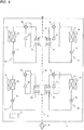
- the water-side heat exchangers 8a, 8b, 8c, and 8d allow the refrigerant flowing in the respective refrigeration cycles 2 and the water (heat medium) to exchange heat with each other.
- the water inlets of the water-side heat exchanger 8a and the water-side heat exchanger 8b are connected in parallel with a water pipe 9a.
- the water outlets of the water-side heat exchanger 8c and the water-side heat exchanger 8d are connected in parallel with a water pipe 9b.
- the water outlet of the water-side heat exchanger 8a and the water inlet of the water-side heat exchanger 8c are connected in series with a water pipe 9c.
- the water outlet of the water-side heat exchanger 8b and the water inlet of the water-side heat exchanger 8d are connected in series with a water pipe 9d.
- the water-side heat exchangers 8a, 8b, 8c, and 8d correspond to the "heat medium-side heat exchangers" in the present invention.
- the water pipes 9c and 9d correspond to the "first heat medium passage” and "second heat medium passage,” respectively, in the present invention.
- elements having an same configuration may be collectively referred to as "water-side heat exchangers 8.”
- a high humidity of the air and a low temperature equal to or lower than 0 degrees C at the heat transferring surfaces of the air-side heat exchangers 5 cause the water vapor in the air to condense and freeze and thus generate frost on the heat transferring surfaces.
- the frost on the air-side heat exchangers 5 increases the wind resistance thereof, resulting in insufficient performance of the air-side heat exchangers 5. This problem requires a defrosting operation for melting the frost on the air-side heat exchangers 5, which needs a heat source for melting the frost.
- the heat source controller 11 determines whether any one of the four refrigeration cycles 2a, 2b, 2c, and 2d is to conduct the defrosting operation. If any one of the refrigeration cycles is to conduct the defrosting operation; then the process goes to Step S5; otherwise the process goes to Step S1.
- the heat source controller 11 conducts the defrosting operation of the refrigeration cycle 2 being a target. The process then goes to Step S1.
- the water-side heat exchangers 8 according to Embodiment 2 are individually disposed in the respective refrigeration cycles 2a, 2b, 2c, and 2d. Even if any water-side heat exchanger 8 is punctured by freezing of water, for example, the other refrigeration cycles 2 can continue the operation for the moment because of the independent water-side heat exchangers 8.
- the water from the refrigeration cycle 2a and the water from the refrigeration cycle 2b join each other in the water pipe 9g.
- This configuration can suppress a decrease in the temperature of the water entering the refrigeration cycle 2c and the refrigeration cycle 2d and thus can stabilize the heating operations of the refrigeration cycle 2c and the refrigeration cycle 2d.
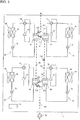
- Fig. 5 is a schematic diagram illustrating the configuration of the refrigeration cycle apparatus according to Embodiment 3 of the invention.
- the basic configuration of the heat source device 1 according to Embodiment 4 is same as that of the heat source device 1 according to Embodiment 1.
- the following description of Embodiment 3 thus focuses on the difference from Embodiment 1, i.e., the configuration of the water pipes 9 and additional valves 12 in the water pipes 9.
- the water inlets of the water-side heat exchanger 8a and the water-side heat exchanger 8b are connected in parallel with a water pipe 9m.
- the water outlets of the water-side heat exchanger 8c and the water-side heat exchanger 8d are connected in parallel with a water pipe 9n.
- the water outlet of the water-side heat exchanger 8a and the water inlet of the water-side heat exchanger 8c are connected in series with a water pipe 9o.
- the water outlet of the water-side heat exchanger 8b and the water inlet of the water-side heat exchanger 8d are connected in series with a water pipe 9p.
- This heat source controller 11 can vary the combination of the water pipes 9 in which water flows by switching the valves 12 depending on the operational mode of the heat source device 1.
- the heat source controller 11 can also vary the range of the flow rate of water in the heat source device 1.
- the heat source controller 11 can vary the combination of the water pipes 9 in which water flows and also vary the range of the flow rate of water in the heat source device 1 by switching the valves 12. That is, the range of the flow rate of water in the heat source device 1 can be varied by on-site operations of the heat source controller 11 to transmit signals to the valves 12 for switching the valves 12, without reconstruction of the water pipes 9.
Landscapes
- Engineering & Computer Science (AREA)
- Physics & Mathematics (AREA)
- Mechanical Engineering (AREA)
- Thermal Sciences (AREA)
- General Engineering & Computer Science (AREA)
- Other Air-Conditioning Systems (AREA)
- Heat-Pump Type And Storage Water Heaters (AREA)
Claims (5)
- Kältekreislaufvorrichtung, umfassend:eine Vielzahl von Kältekreisläufen (2a-2d), die es einem Kältemittel erlaubt, darin zu zirkulieren, wobei jeder der Kältekreisläufe (2a-2d) einen Kompressor (3a-3d), eine Kältemittelstrom-Schaltvorrichtung (4a-4d), einen luftseitigen Wärmetauscher (5a-5d), eine Druckverringerungsvorrichtung (7a-7d) und einen wärmemediumseitigen Wärmetauscher (8a-8d) umfasst, die in Reihe mit Kältemittelrohren verbunden sind, wobei die wärmemediumseitigen Wärmetauscher (8a-8d) es einem Wärmemedium und dem Kältemittel ermöglichen, Wärme miteinander auszutauschen;einen Wärmemediumauslass eines ersten wärmemediumseitigen Wärmetauschers (8a) und einen Wärmemediumeinlass eines dritten wärmemediumseitigen Wärmetauschers (8c), die in Reihe mit einem ersten Wärmemediumdurchlass (9o) verbunden sind,einen Wärmemediumauslass eines zweiten wärmemediumseitigen Wärmetauschers (8b) und einen Wärmemediumeinlass eines vierten wärmemediumseitigen Wärmetauschers (8d), die in Reihe mit einem zweiten Wärmemediumdurchlass (9p) verbunden sind,wobei der erste Wärmemediumdurchlass (9o) und der zweite Wärmemediumdurchlass (9p) parallel miteinander verbunden sind, wobei die Wärmemediumeinlässe des ersten wärmeseitigen Wärmetauschers (8a) und des zweiten wärmemediumseitigen Wärmetauschers (8b) parallel mit einem ersten Rohr (9m) verbunden sind und wobei die Wärmemediumauslässe des dritten wärmemediumseitigen Wärmetauschers (8c) und des vierten wärmemediumseitigen Wärmetauschers (8d) parallel mit einem zweiten Rohr (9n) verbunden sind,ein Wärmemediumauslass des ersten wärmemediumseitigen Wärmetauschers (8a) und der Wärmemediumeinlass des zweiten wärmemediumseitigen Wärmetauschers (8b) in Reihe mit einem dritten Rohr (9q) verbunden sind,der Wärmemediumauslass des vierten wärmemediumseitigen Wärmetauschers (8d) und ein Wärmemediumeinlass des dritten wärmemediumseitigen Wärmetauschers (8c) in Reihe mit einem vierten Rohr (9r) verbunden sind,das erste Rohr (9m) eine erste Verzweigung (13a) aufweist, von der aus sich das erste Rohr (9m) in den ersten wärmemediumseitigen Wärmetauscher (8a) und den zweiten wärmemediumseitigen Wärmetauscher (8b) verzweigt,das erste Rohr (9m) ein erstes Ventil (12a) zwischen der ersten Verzweigung (13a) und dem Wärmemediumeinlass des zweiten wärmemediumseitigen Wärmetauschers (8b) aufweist,das zweite Rohr (9n) eine zweite Verzweigung (13b) aufweist, von der aus sich das zweite Rohr (9n) in den dritten wärmemediumseitigen Wärmetauscher (8c) und den vierten wärmemediumseitigen Wärmetauscher (8d) verzweigt,das zweite Rohr (9n) ein zweites Ventil (12b) zwischen der zweiten Verzweigung (13b) und dem Wärmemediumauslass des vierten wärmemediumseitigen Wärmetauschers (8d) aufweist, unddas dritte Rohr (9q), das vierte Rohr (9r) und die ersten Wärmemediumdurchlässe (9o) ein drittes Ventil (12c), ein viertes Ventil (12d) bzw. ein fünftes Ventil (12e) aufweisen.
- Kältekreislaufvorrichtung nach Anspruch 1, ferner umfassend Gebläse (6a-6d) für die luftseitigen Wärmetauscher (5a-5d) und eine Wärmequellen-Steuervorrichtung (11), die ausgelegt ist, die Kompressoren (3a-3d), die Kältemittelstrom-Schaltvorrichtungen (4a-4d), die Druckverringerungsvorrichtungen (7a-7d) und die Gebläse (6a-6d) für die luftseitigen Wärmetauscher (5a-5d) zu steuern,
wobei die Wärmequellen-Steuervorrichtung (11) ausgelegt ist, um zu bestimmen, ob die Kältekreisläufe (2a-2d) Abtauvorgänge durchführen. - Kältekreislaufvorrichtung nach Anspruch 2, wobei
die Wärmequellen-Steuervorrichtung (11) ausgelegt ist, um, wenn gleichzeitige Abtauvorgänge der Kältekreisläufe (2a-2d) durchgeführt werden können, die Abtauvorgänge aller Kältekreisläufe (2a-2d) durchzuführen, oder andernfalls einen Abtauvorgang eines Kältekreislaufes (2a-2d) durchzuführen, der ein Abtauziel unter den Kältekreisläufen (2a-2d) ist. - Kältekreislaufvorrichtung nach Anspruch 1, ferner umfassend Gebläse (6a-6d) für die luftseitigen Wärmetauscher (5a-5d) und eine Wärmequellen-Steuervorrichtung (11), die ausgelegt ist, um den Kompressor (3a-3d), die Kältemittelstrom-Schaltvorrichtung (4a-4d), die Druckverringerungsvorrichtung (7a-7d) und die Gebläse (6a-6d) für die luftseitigen Wärmetauscher (5a-5d) zu steuern,
wobei die Wärmequellen-Steuervorrichtung (11) ausgelegt ist, um einen ersten Schritt (S1) des Bestimmens, ob gleichzeitige Abtauvorgänge der Vielzahl von Kältekreisläufen (2a-2d) durchgeführt werden können, und
einen zweiten Schritt (S2, S4) des Bestimmens, ob einer der Kältekreisläufe (2a-2d) einen Abtauvorgang durchführt,
auszuführen, und
wenn in dem ersten Schritt bestimmt wird, dass die gleichzeitigen Abtauvorgänge der Vielzahl von Kältekreisläufen (2a-2d) durchgeführt werden können, und wenn in dem zweiten Schritt bestimmt wird, dass einer der Kältekreisläufe (2a-2d) einen Abtauvorgang durchführt, die Abtauvorgänge aller Kältekreisläufe durchzuführen, während
wenn in dem ersten Schritt bestimmt wird, dass die gleichzeitigen Abtauvorgänge der Vielzahl von Kältekreisläufen (2a-2d) nicht durchgeführt werden können, und in dem zweiten Schritt bestimmt wird, dass einer der Kältekreisläufe (2a-2d) einen Abtauvorgang durchführt, einen dritten Schritt (S5) des Bestimmens, ob zumindest einer der Kältekreisläufe (2a-2d), der keiner der Kältekreisläufe ist, die die Abtauvorgänge durchführen, den Abtauvorgang durchführt, auszuführen, und
den Abtauvorgang von zumindest einem der Kältekreisläufe, die die Kältekreisläufe sind, die die Abtauvorgänge durchführen, durchzuführen, wenn in dem dritten Schritt (S5) bestimmt wird, dass die Kältekreisläufe (2a-2d), die nicht die Kältekreisläufe sind, die die Abtauvorgänge durchführen, nicht die Abtauvorgänge durchführen. - Kältekreislaufvorrichtung nach einem der Ansprüche 1 bis 4, wobei der erste Wärmemediumdurchlass (9o) und der zweite Wärmemediumdurchlass (9p) in der Lage sind, neu angeordnet zu werden.
Applications Claiming Priority (1)
| Application Number | Priority Date | Filing Date | Title |
|---|---|---|---|
| PCT/JP2014/082295 WO2016088262A1 (ja) | 2014-12-05 | 2014-12-05 | 冷凍サイクル装置 |
Publications (3)
| Publication Number | Publication Date |
|---|---|
| EP3228951A1 EP3228951A1 (de) | 2017-10-11 |
| EP3228951A4 EP3228951A4 (de) | 2018-07-04 |
| EP3228951B1 true EP3228951B1 (de) | 2021-01-27 |
Family
ID=56091233
Family Applications (1)
| Application Number | Title | Priority Date | Filing Date |
|---|---|---|---|
| EP14907314.0A Active EP3228951B1 (de) | 2014-12-05 | 2014-12-05 | Kältekreislaufvorrichtung |
Country Status (3)
| Country | Link |
|---|---|
| EP (1) | EP3228951B1 (de) |
| JP (1) | JP6410839B2 (de) |
| WO (1) | WO2016088262A1 (de) |
Families Citing this family (8)
| Publication number | Priority date | Publication date | Assignee | Title |
|---|---|---|---|---|
| JP6707192B2 (ja) * | 2017-05-19 | 2020-06-10 | 三菱電機株式会社 | チリングユニット及び水循環温調システム |
| JP6861821B2 (ja) * | 2017-08-03 | 2021-04-21 | 三菱電機株式会社 | 冷凍サイクル装置 |
| US20210048216A1 (en) * | 2018-03-02 | 2021-02-18 | Mitsubishi Electric Corporation | Air-conditioning apparatus |
| WO2019171486A1 (ja) * | 2018-03-07 | 2019-09-12 | 三菱電機株式会社 | 熱源装置および冷凍サイクル装置 |
| WO2021024404A1 (ja) * | 2019-08-07 | 2021-02-11 | 三菱電機株式会社 | チリングユニット及び空気調和システム |
| CN110617644A (zh) * | 2019-10-18 | 2019-12-27 | 珠海格力节能环保制冷技术研究中心有限公司 | 换热系统、空调器及空调器的控制方法 |
| JP7414586B2 (ja) * | 2020-02-28 | 2024-01-16 | 住友重機械工業株式会社 | 極低温冷凍機用圧縮機システムおよび補助冷却装置 |
| WO2024180660A1 (ja) * | 2023-02-28 | 2024-09-06 | 三菱電機株式会社 | 給湯システム |
Family Cites Families (13)
| Publication number | Priority date | Publication date | Assignee | Title |
|---|---|---|---|---|
| JP2697376B2 (ja) * | 1991-07-11 | 1998-01-14 | ダイキン工業株式会社 | 二元冷凍サイクルを有する冷却装置のためのデフロスト装置 |
| JPH05322265A (ja) * | 1992-05-28 | 1993-12-07 | Toshiba Corp | 空気調和機 |
| JPH07127954A (ja) * | 1993-06-15 | 1995-05-19 | Daikin Ind Ltd | 冷凍装置 |
| JPH07332817A (ja) * | 1994-06-08 | 1995-12-22 | Daikin Ind Ltd | ヒートポンプ式冷凍装置 |
| JP3394379B2 (ja) * | 1996-01-18 | 2003-04-07 | 松下エコシステムズ株式会社 | 熱交ユニット及び多室型空気調和装置 |
| JPH10267494A (ja) * | 1997-03-25 | 1998-10-09 | Mitsubishi Electric Corp | 冷却装置 |
| JP3438000B2 (ja) * | 2000-08-04 | 2003-08-18 | 株式会社日立製作所 | 空気調和機 |
| JP2002195609A (ja) * | 2000-12-26 | 2002-07-10 | Matsushita Electric Ind Co Ltd | 冷凍装置 |
| JP2006170505A (ja) * | 2004-12-15 | 2006-06-29 | Matsushita Electric Ind Co Ltd | 空気調和機 |
| JP5247853B2 (ja) * | 2011-07-04 | 2013-07-24 | 三菱電機株式会社 | 空調システム |
| WO2013021762A1 (ja) * | 2011-08-05 | 2013-02-14 | 東芝キヤリア株式会社 | 加温システム |
| JP5809872B2 (ja) * | 2011-08-08 | 2015-11-11 | 東芝キヤリア株式会社 | 加温装置 |
| JP5931412B2 (ja) * | 2011-11-22 | 2016-06-08 | 三菱重工業株式会社 | ヒートポンプシステム |
-
2014
- 2014-12-05 JP JP2016562178A patent/JP6410839B2/ja active Active
- 2014-12-05 WO PCT/JP2014/082295 patent/WO2016088262A1/ja not_active Ceased
- 2014-12-05 EP EP14907314.0A patent/EP3228951B1/de active Active
Non-Patent Citations (1)
| Title |
|---|
| None * |
Also Published As
| Publication number | Publication date |
|---|---|
| EP3228951A1 (de) | 2017-10-11 |
| WO2016088262A1 (ja) | 2016-06-09 |
| JPWO2016088262A1 (ja) | 2017-04-27 |
| JP6410839B2 (ja) | 2018-10-24 |
| EP3228951A4 (de) | 2018-07-04 |
Similar Documents
| Publication | Publication Date | Title |
|---|---|---|
| EP3228951B1 (de) | Kältekreislaufvorrichtung | |
| US11268743B2 (en) | Air-conditioning apparatus having heating-defrosting operation mode | |
| EP2975339B1 (de) | Klimaanlagenvorrichtung mit einheit zur erhöhung der heizleistung | |
| US10006678B2 (en) | Air-conditioning apparatus | |
| US10852027B2 (en) | Air conditioning system | |
| EP2669598B1 (de) | Klimaanlage | |
| JP6138711B2 (ja) | 空気調和装置 | |
| WO2013099047A1 (ja) | 空気調和装置 | |
| US10393418B2 (en) | Air-conditioning apparatus | |
| EP3379159B1 (de) | Klimaanlage | |
| US11874039B2 (en) | Refrigeration cycle apparatus | |
| JPWO2019224945A1 (ja) | 冷凍サイクル装置 | |
| JP6880204B2 (ja) | 空気調和装置 | |
| CN111854202A (zh) | 一种冷柜设备、制冷系统及其控制方法 | |
| JP6415701B2 (ja) | 冷凍サイクル装置 | |
| EP3236168B1 (de) | Klimatisierungsvorrichtung | |
| CN115038917A (zh) | 空调 | |
| KR20200007771A (ko) | 냉동 장치 및 온도 제어 장치 | |
| CN101270905A (zh) | 同时加热冷却型多空调及其控制方法 | |
| US20150211776A1 (en) | Air-conditioning apparatus | |
| JP6804648B2 (ja) | 冷凍サイクル装置 | |
| US20210048216A1 (en) | Air-conditioning apparatus | |
| CN116518480A (zh) | 空调及用于空调控制的方法、装置和存储介质 | |
| CN111854206A (zh) | 一种冷柜设备、制冷系统及其控制方法 | |
| JP2004232905A (ja) | 冷凍装置 |
Legal Events
| Date | Code | Title | Description |
|---|---|---|---|
| STAA | Information on the status of an ep patent application or granted ep patent |
Free format text: STATUS: THE INTERNATIONAL PUBLICATION HAS BEEN MADE |
|
| PUAI | Public reference made under article 153(3) epc to a published international application that has entered the european phase |
Free format text: ORIGINAL CODE: 0009012 |
|
| STAA | Information on the status of an ep patent application or granted ep patent |
Free format text: STATUS: REQUEST FOR EXAMINATION WAS MADE |
|
| 17P | Request for examination filed |
Effective date: 20170419 |
|
| AK | Designated contracting states |
Kind code of ref document: A1 Designated state(s): AL AT BE BG CH CY CZ DE DK EE ES FI FR GB GR HR HU IE IS IT LI LT LU LV MC MK MT NL NO PL PT RO RS SE SI SK SM TR |
|
| AX | Request for extension of the european patent |
Extension state: BA ME |
|
| DAX | Request for extension of the european patent (deleted) | ||
| A4 | Supplementary search report drawn up and despatched |
Effective date: 20180604 |
|
| RIC1 | Information provided on ipc code assigned before grant |
Ipc: F25B 49/02 20060101ALI20180528BHEP Ipc: F25B 13/00 20060101ALI20180528BHEP Ipc: F25B 47/02 20060101ALI20180528BHEP Ipc: F25B 1/00 20060101AFI20180528BHEP |
|
| STAA | Information on the status of an ep patent application or granted ep patent |
Free format text: STATUS: EXAMINATION IS IN PROGRESS |
|
| 17Q | First examination report despatched |
Effective date: 20200430 |
|
| GRAP | Despatch of communication of intention to grant a patent |
Free format text: ORIGINAL CODE: EPIDOSNIGR1 |
|
| STAA | Information on the status of an ep patent application or granted ep patent |
Free format text: STATUS: GRANT OF PATENT IS INTENDED |
|
| INTG | Intention to grant announced |
Effective date: 20200813 |
|
| GRAJ | Information related to disapproval of communication of intention to grant by the applicant or resumption of examination proceedings by the epo deleted |
Free format text: ORIGINAL CODE: EPIDOSDIGR1 |
|
| STAA | Information on the status of an ep patent application or granted ep patent |
Free format text: STATUS: EXAMINATION IS IN PROGRESS |
|
| GRAP | Despatch of communication of intention to grant a patent |
Free format text: ORIGINAL CODE: EPIDOSNIGR1 |
|
| STAA | Information on the status of an ep patent application or granted ep patent |
Free format text: STATUS: GRANT OF PATENT IS INTENDED |
|
| INTC | Intention to grant announced (deleted) | ||
| INTG | Intention to grant announced |
Effective date: 20201022 |
|
| GRAS | Grant fee paid |
Free format text: ORIGINAL CODE: EPIDOSNIGR3 |
|
| GRAA | (expected) grant |
Free format text: ORIGINAL CODE: 0009210 |
|
| STAA | Information on the status of an ep patent application or granted ep patent |
Free format text: STATUS: THE PATENT HAS BEEN GRANTED |
|
| AK | Designated contracting states |
Kind code of ref document: B1 Designated state(s): AL AT BE BG CH CY CZ DE DK EE ES FI FR GB GR HR HU IE IS IT LI LT LU LV MC MK MT NL NO PL PT RO RS SE SI SK SM TR |
|
| REG | Reference to a national code |
Ref country code: GB Ref legal event code: FG4D |
|
| REG | Reference to a national code |
Ref country code: CH Ref legal event code: EP |
|
| REG | Reference to a national code |
Ref country code: AT Ref legal event code: REF Ref document number: 1358706 Country of ref document: AT Kind code of ref document: T Effective date: 20210215 |
|
| REG | Reference to a national code |
Ref country code: IE Ref legal event code: FG4D |
|
| REG | Reference to a national code |
Ref country code: DE Ref legal event code: R096 Ref document number: 602014074681 Country of ref document: DE |
|
| REG | Reference to a national code |
Ref country code: NL Ref legal event code: MP Effective date: 20210127 |
|
| REG | Reference to a national code |
Ref country code: LT Ref legal event code: MG9D |
|
| REG | Reference to a national code |
Ref country code: AT Ref legal event code: MK05 Ref document number: 1358706 Country of ref document: AT Kind code of ref document: T Effective date: 20210127 |
|
| PG25 | Lapsed in a contracting state [announced via postgrant information from national office to epo] |
Ref country code: LT Free format text: LAPSE BECAUSE OF FAILURE TO SUBMIT A TRANSLATION OF THE DESCRIPTION OR TO PAY THE FEE WITHIN THE PRESCRIBED TIME-LIMIT Effective date: 20210127 Ref country code: PT Free format text: LAPSE BECAUSE OF FAILURE TO SUBMIT A TRANSLATION OF THE DESCRIPTION OR TO PAY THE FEE WITHIN THE PRESCRIBED TIME-LIMIT Effective date: 20210527 Ref country code: HR Free format text: LAPSE BECAUSE OF FAILURE TO SUBMIT A TRANSLATION OF THE DESCRIPTION OR TO PAY THE FEE WITHIN THE PRESCRIBED TIME-LIMIT Effective date: 20210127 Ref country code: GR Free format text: LAPSE BECAUSE OF FAILURE TO SUBMIT A TRANSLATION OF THE DESCRIPTION OR TO PAY THE FEE WITHIN THE PRESCRIBED TIME-LIMIT Effective date: 20210428 Ref country code: FI Free format text: LAPSE BECAUSE OF FAILURE TO SUBMIT A TRANSLATION OF THE DESCRIPTION OR TO PAY THE FEE WITHIN THE PRESCRIBED TIME-LIMIT Effective date: 20210127 Ref country code: BG Free format text: LAPSE BECAUSE OF FAILURE TO SUBMIT A TRANSLATION OF THE DESCRIPTION OR TO PAY THE FEE WITHIN THE PRESCRIBED TIME-LIMIT Effective date: 20210427 Ref country code: NO Free format text: LAPSE BECAUSE OF FAILURE TO SUBMIT A TRANSLATION OF THE DESCRIPTION OR TO PAY THE FEE WITHIN THE PRESCRIBED TIME-LIMIT Effective date: 20210427 |
|
| PG25 | Lapsed in a contracting state [announced via postgrant information from national office to epo] |
Ref country code: SE Free format text: LAPSE BECAUSE OF FAILURE TO SUBMIT A TRANSLATION OF THE DESCRIPTION OR TO PAY THE FEE WITHIN THE PRESCRIBED TIME-LIMIT Effective date: 20210127 Ref country code: AT Free format text: LAPSE BECAUSE OF FAILURE TO SUBMIT A TRANSLATION OF THE DESCRIPTION OR TO PAY THE FEE WITHIN THE PRESCRIBED TIME-LIMIT Effective date: 20210127 Ref country code: RS Free format text: LAPSE BECAUSE OF FAILURE TO SUBMIT A TRANSLATION OF THE DESCRIPTION OR TO PAY THE FEE WITHIN THE PRESCRIBED TIME-LIMIT Effective date: 20210127 Ref country code: PL Free format text: LAPSE BECAUSE OF FAILURE TO SUBMIT A TRANSLATION OF THE DESCRIPTION OR TO PAY THE FEE WITHIN THE PRESCRIBED TIME-LIMIT Effective date: 20210127 Ref country code: LV Free format text: LAPSE BECAUSE OF FAILURE TO SUBMIT A TRANSLATION OF THE DESCRIPTION OR TO PAY THE FEE WITHIN THE PRESCRIBED TIME-LIMIT Effective date: 20210127 |
|
| PG25 | Lapsed in a contracting state [announced via postgrant information from national office to epo] |
Ref country code: IS Free format text: LAPSE BECAUSE OF FAILURE TO SUBMIT A TRANSLATION OF THE DESCRIPTION OR TO PAY THE FEE WITHIN THE PRESCRIBED TIME-LIMIT Effective date: 20210527 |
|
| REG | Reference to a national code |
Ref country code: DE Ref legal event code: R097 Ref document number: 602014074681 Country of ref document: DE |
|
| PG25 | Lapsed in a contracting state [announced via postgrant information from national office to epo] |
Ref country code: SM Free format text: LAPSE BECAUSE OF FAILURE TO SUBMIT A TRANSLATION OF THE DESCRIPTION OR TO PAY THE FEE WITHIN THE PRESCRIBED TIME-LIMIT Effective date: 20210127 Ref country code: CZ Free format text: LAPSE BECAUSE OF FAILURE TO SUBMIT A TRANSLATION OF THE DESCRIPTION OR TO PAY THE FEE WITHIN THE PRESCRIBED TIME-LIMIT Effective date: 20210127 Ref country code: EE Free format text: LAPSE BECAUSE OF FAILURE TO SUBMIT A TRANSLATION OF THE DESCRIPTION OR TO PAY THE FEE WITHIN THE PRESCRIBED TIME-LIMIT Effective date: 20210127 |
|
| PG25 | Lapsed in a contracting state [announced via postgrant information from national office to epo] |
Ref country code: RO Free format text: LAPSE BECAUSE OF FAILURE TO SUBMIT A TRANSLATION OF THE DESCRIPTION OR TO PAY THE FEE WITHIN THE PRESCRIBED TIME-LIMIT Effective date: 20210127 Ref country code: SK Free format text: LAPSE BECAUSE OF FAILURE TO SUBMIT A TRANSLATION OF THE DESCRIPTION OR TO PAY THE FEE WITHIN THE PRESCRIBED TIME-LIMIT Effective date: 20210127 Ref country code: DK Free format text: LAPSE BECAUSE OF FAILURE TO SUBMIT A TRANSLATION OF THE DESCRIPTION OR TO PAY THE FEE WITHIN THE PRESCRIBED TIME-LIMIT Effective date: 20210127 |
|
| PLBE | No opposition filed within time limit |
Free format text: ORIGINAL CODE: 0009261 |
|
| STAA | Information on the status of an ep patent application or granted ep patent |
Free format text: STATUS: NO OPPOSITION FILED WITHIN TIME LIMIT |
|
| 26N | No opposition filed |
Effective date: 20211028 |
|
| PG25 | Lapsed in a contracting state [announced via postgrant information from national office to epo] |
Ref country code: AL Free format text: LAPSE BECAUSE OF FAILURE TO SUBMIT A TRANSLATION OF THE DESCRIPTION OR TO PAY THE FEE WITHIN THE PRESCRIBED TIME-LIMIT Effective date: 20210127 Ref country code: ES Free format text: LAPSE BECAUSE OF FAILURE TO SUBMIT A TRANSLATION OF THE DESCRIPTION OR TO PAY THE FEE WITHIN THE PRESCRIBED TIME-LIMIT Effective date: 20210127 |
|
| PG25 | Lapsed in a contracting state [announced via postgrant information from national office to epo] |
Ref country code: SI Free format text: LAPSE BECAUSE OF FAILURE TO SUBMIT A TRANSLATION OF THE DESCRIPTION OR TO PAY THE FEE WITHIN THE PRESCRIBED TIME-LIMIT Effective date: 20210127 |
|
| PG25 | Lapsed in a contracting state [announced via postgrant information from national office to epo] |
Ref country code: IT Free format text: LAPSE BECAUSE OF FAILURE TO SUBMIT A TRANSLATION OF THE DESCRIPTION OR TO PAY THE FEE WITHIN THE PRESCRIBED TIME-LIMIT Effective date: 20210127 |
|
| PG25 | Lapsed in a contracting state [announced via postgrant information from national office to epo] |
Ref country code: IS Free format text: LAPSE BECAUSE OF FAILURE TO SUBMIT A TRANSLATION OF THE DESCRIPTION OR TO PAY THE FEE WITHIN THE PRESCRIBED TIME-LIMIT Effective date: 20210527 |
|
| REG | Reference to a national code |
Ref country code: DE Ref legal event code: R119 Ref document number: 602014074681 Country of ref document: DE |
|
| PG25 | Lapsed in a contracting state [announced via postgrant information from national office to epo] |
Ref country code: MC Free format text: LAPSE BECAUSE OF FAILURE TO SUBMIT A TRANSLATION OF THE DESCRIPTION OR TO PAY THE FEE WITHIN THE PRESCRIBED TIME-LIMIT Effective date: 20210127 |
|
| REG | Reference to a national code |
Ref country code: CH Ref legal event code: PL |
|
| REG | Reference to a national code |
Ref country code: BE Ref legal event code: MM Effective date: 20211231 |
|
| PG25 | Lapsed in a contracting state [announced via postgrant information from national office to epo] |
Ref country code: LU Free format text: LAPSE BECAUSE OF NON-PAYMENT OF DUE FEES Effective date: 20211205 Ref country code: IE Free format text: LAPSE BECAUSE OF NON-PAYMENT OF DUE FEES Effective date: 20211205 Ref country code: DE Free format text: LAPSE BECAUSE OF NON-PAYMENT OF DUE FEES Effective date: 20220701 |
|
| PG25 | Lapsed in a contracting state [announced via postgrant information from national office to epo] |
Ref country code: FR Free format text: LAPSE BECAUSE OF NON-PAYMENT OF DUE FEES Effective date: 20211231 Ref country code: BE Free format text: LAPSE BECAUSE OF NON-PAYMENT OF DUE FEES Effective date: 20211231 |
|
| PG25 | Lapsed in a contracting state [announced via postgrant information from national office to epo] |
Ref country code: LI Free format text: LAPSE BECAUSE OF NON-PAYMENT OF DUE FEES Effective date: 20211231 Ref country code: CH Free format text: LAPSE BECAUSE OF NON-PAYMENT OF DUE FEES Effective date: 20211231 |
|
| PG25 | Lapsed in a contracting state [announced via postgrant information from national office to epo] |
Ref country code: HU Free format text: LAPSE BECAUSE OF FAILURE TO SUBMIT A TRANSLATION OF THE DESCRIPTION OR TO PAY THE FEE WITHIN THE PRESCRIBED TIME-LIMIT; INVALID AB INITIO Effective date: 20141205 |
|
| PG25 | Lapsed in a contracting state [announced via postgrant information from national office to epo] |
Ref country code: NL Free format text: LAPSE BECAUSE OF NON-PAYMENT OF DUE FEES Effective date: 20210127 Ref country code: CY Free format text: LAPSE BECAUSE OF FAILURE TO SUBMIT A TRANSLATION OF THE DESCRIPTION OR TO PAY THE FEE WITHIN THE PRESCRIBED TIME-LIMIT Effective date: 20210127 |
|
| REG | Reference to a national code |
Ref country code: GB Ref legal event code: 746 Effective date: 20240319 |
|
| PG25 | Lapsed in a contracting state [announced via postgrant information from national office to epo] |
Ref country code: MK Free format text: LAPSE BECAUSE OF FAILURE TO SUBMIT A TRANSLATION OF THE DESCRIPTION OR TO PAY THE FEE WITHIN THE PRESCRIBED TIME-LIMIT Effective date: 20210127 |
|
| PG25 | Lapsed in a contracting state [announced via postgrant information from national office to epo] |
Ref country code: TR Free format text: LAPSE BECAUSE OF FAILURE TO SUBMIT A TRANSLATION OF THE DESCRIPTION OR TO PAY THE FEE WITHIN THE PRESCRIBED TIME-LIMIT Effective date: 20210127 |
|
| PG25 | Lapsed in a contracting state [announced via postgrant information from national office to epo] |
Ref country code: MT Free format text: LAPSE BECAUSE OF FAILURE TO SUBMIT A TRANSLATION OF THE DESCRIPTION OR TO PAY THE FEE WITHIN THE PRESCRIBED TIME-LIMIT Effective date: 20210127 |
|
| PGFP | Annual fee paid to national office [announced via postgrant information from national office to epo] |
Ref country code: GB Payment date: 20251030 Year of fee payment: 12 |