EP3231673A1 - Reinigungssystem der windschutzscheibe eines fahrzeugs - Google Patents
Reinigungssystem der windschutzscheibe eines fahrzeugs Download PDFInfo
- Publication number
- EP3231673A1 EP3231673A1 EP17162609.6A EP17162609A EP3231673A1 EP 3231673 A1 EP3231673 A1 EP 3231673A1 EP 17162609 A EP17162609 A EP 17162609A EP 3231673 A1 EP3231673 A1 EP 3231673A1
- Authority
- EP
- European Patent Office
- Prior art keywords
- connecting piece
- wiper blade
- drive arm
- arm
- connector
- Prior art date
- Legal status (The legal status is an assumption and is not a legal conclusion. Google has not performed a legal analysis and makes no representation as to the accuracy of the status listed.)
- Withdrawn
Links
- 239000011521 glass Substances 0.000 claims abstract description 22
- 239000007788 liquid Substances 0.000 claims abstract description 20
- 238000000034 method Methods 0.000 claims description 8
- 238000005452 bending Methods 0.000 claims description 4
- 235000015243 ice cream Nutrition 0.000 claims 1
- 244000007853 Sarothamnus scoparius Species 0.000 description 21
- 239000012530 fluid Substances 0.000 description 13
- 230000008901 benefit Effects 0.000 description 4
- 238000005516 engineering process Methods 0.000 description 4
- 230000000712 assembly Effects 0.000 description 3
- 238000000429 assembly Methods 0.000 description 3
- 238000005507 spraying Methods 0.000 description 3
- 238000006073 displacement reaction Methods 0.000 description 2
- 238000003780 insertion Methods 0.000 description 2
- 230000037431 insertion Effects 0.000 description 2
- 230000014759 maintenance of location Effects 0.000 description 2
- XLYOFNOQVPJJNP-UHFFFAOYSA-N water Substances O XLYOFNOQVPJJNP-UHFFFAOYSA-N 0.000 description 2
- 230000005489 elastic deformation Effects 0.000 description 1
- 238000007747 plating Methods 0.000 description 1
- 238000000926 separation method Methods 0.000 description 1
- 239000007921 spray Substances 0.000 description 1
Images



Classifications
-
- B—PERFORMING OPERATIONS; TRANSPORTING
- B60—VEHICLES IN GENERAL
- B60S—SERVICING, CLEANING, REPAIRING, SUPPORTING, LIFTING, OR MANOEUVRING OF VEHICLES, NOT OTHERWISE PROVIDED FOR
- B60S1/00—Cleaning of vehicles
- B60S1/02—Cleaning windscreens, windows or optical devices
- B60S1/04—Wipers or the like, e.g. scrapers
- B60S1/32—Wipers or the like, e.g. scrapers characterised by constructional features of wiper blade arms or blades
-
- B—PERFORMING OPERATIONS; TRANSPORTING
- B60—VEHICLES IN GENERAL
- B60S—SERVICING, CLEANING, REPAIRING, SUPPORTING, LIFTING, OR MANOEUVRING OF VEHICLES, NOT OTHERWISE PROVIDED FOR
- B60S1/00—Cleaning of vehicles
- B60S1/02—Cleaning windscreens, windows or optical devices
- B60S1/04—Wipers or the like, e.g. scrapers
- B60S1/32—Wipers or the like, e.g. scrapers characterised by constructional features of wiper blade arms or blades
- B60S1/34—Wiper arms; Mountings therefor
- B60S1/3415—Wiper arms; Mountings therefor with means for supplying cleaning fluid to windscreen cleaners, e.g. washers
-
- B—PERFORMING OPERATIONS; TRANSPORTING
- B60—VEHICLES IN GENERAL
- B60S—SERVICING, CLEANING, REPAIRING, SUPPORTING, LIFTING, OR MANOEUVRING OF VEHICLES, NOT OTHERWISE PROVIDED FOR
- B60S1/00—Cleaning of vehicles
- B60S1/02—Cleaning windscreens, windows or optical devices
- B60S1/04—Wipers or the like, e.g. scrapers
- B60S1/32—Wipers or the like, e.g. scrapers characterised by constructional features of wiper blade arms or blades
- B60S1/34—Wiper arms; Mountings therefor
- B60S1/3425—Constructional aspects of the arm
-
- B—PERFORMING OPERATIONS; TRANSPORTING
- B60—VEHICLES IN GENERAL
- B60S—SERVICING, CLEANING, REPAIRING, SUPPORTING, LIFTING, OR MANOEUVRING OF VEHICLES, NOT OTHERWISE PROVIDED FOR
- B60S1/00—Cleaning of vehicles
- B60S1/02—Cleaning windscreens, windows or optical devices
- B60S1/04—Wipers or the like, e.g. scrapers
- B60S1/32—Wipers or the like, e.g. scrapers characterised by constructional features of wiper blade arms or blades
- B60S1/38—Wiper blades
-
- B—PERFORMING OPERATIONS; TRANSPORTING
- B60—VEHICLES IN GENERAL
- B60S—SERVICING, CLEANING, REPAIRING, SUPPORTING, LIFTING, OR MANOEUVRING OF VEHICLES, NOT OTHERWISE PROVIDED FOR
- B60S1/00—Cleaning of vehicles
- B60S1/02—Cleaning windscreens, windows or optical devices
- B60S1/04—Wipers or the like, e.g. scrapers
- B60S1/32—Wipers or the like, e.g. scrapers characterised by constructional features of wiper blade arms or blades
- B60S1/38—Wiper blades
- B60S1/3848—Flat-type wiper blade, i.e. without harness
- B60S1/3849—Connectors therefor; Connection to wiper arm; Attached to blade
- B60S1/3862—Transport of liquid there through
-
- B—PERFORMING OPERATIONS; TRANSPORTING
- B60—VEHICLES IN GENERAL
- B60S—SERVICING, CLEANING, REPAIRING, SUPPORTING, LIFTING, OR MANOEUVRING OF VEHICLES, NOT OTHERWISE PROVIDED FOR
- B60S1/00—Cleaning of vehicles
- B60S1/02—Cleaning windscreens, windows or optical devices
- B60S1/04—Wipers or the like, e.g. scrapers
- B60S1/32—Wipers or the like, e.g. scrapers characterised by constructional features of wiper blade arms or blades
- B60S1/40—Connections between blades and arms
-
- B—PERFORMING OPERATIONS; TRANSPORTING
- B60—VEHICLES IN GENERAL
- B60S—SERVICING, CLEANING, REPAIRING, SUPPORTING, LIFTING, OR MANOEUVRING OF VEHICLES, NOT OTHERWISE PROVIDED FOR
- B60S1/00—Cleaning of vehicles
- B60S1/02—Cleaning windscreens, windows or optical devices
- B60S1/04—Wipers or the like, e.g. scrapers
- B60S1/32—Wipers or the like, e.g. scrapers characterised by constructional features of wiper blade arms or blades
- B60S1/40—Connections between blades and arms
- B60S1/4067—Connections between blades and arms for arms provided with a side pin
-
- B—PERFORMING OPERATIONS; TRANSPORTING
- B60—VEHICLES IN GENERAL
- B60S—SERVICING, CLEANING, REPAIRING, SUPPORTING, LIFTING, OR MANOEUVRING OF VEHICLES, NOT OTHERWISE PROVIDED FOR
- B60S1/00—Cleaning of vehicles
- B60S1/02—Cleaning windscreens, windows or optical devices
- B60S1/04—Wipers or the like, e.g. scrapers
- B60S1/32—Wipers or the like, e.g. scrapers characterised by constructional features of wiper blade arms or blades
- B60S1/40—Connections between blades and arms
- B60S1/4067—Connections between blades and arms for arms provided with a side pin
- B60S1/407—Connections between blades and arms for arms provided with a side pin with means provided on the arm for locking the side pin
-
- B—PERFORMING OPERATIONS; TRANSPORTING
- B60—VEHICLES IN GENERAL
- B60S—SERVICING, CLEANING, REPAIRING, SUPPORTING, LIFTING, OR MANOEUVRING OF VEHICLES, NOT OTHERWISE PROVIDED FOR
- B60S1/00—Cleaning of vehicles
- B60S1/02—Cleaning windscreens, windows or optical devices
- B60S1/04—Wipers or the like, e.g. scrapers
- B60S1/32—Wipers or the like, e.g. scrapers characterised by constructional features of wiper blade arms or blades
- B60S1/40—Connections between blades and arms
- B60S1/4067—Connections between blades and arms for arms provided with a side pin
- B60S1/4074—Connections between blades and arms for arms provided with a side pin with means provided on the blade for locking the side pin
-
- B—PERFORMING OPERATIONS; TRANSPORTING
- B60—VEHICLES IN GENERAL
- B60S—SERVICING, CLEANING, REPAIRING, SUPPORTING, LIFTING, OR MANOEUVRING OF VEHICLES, NOT OTHERWISE PROVIDED FOR
- B60S1/00—Cleaning of vehicles
- B60S1/02—Cleaning windscreens, windows or optical devices
- B60S1/04—Wipers or the like, e.g. scrapers
- B60S1/32—Wipers or the like, e.g. scrapers characterised by constructional features of wiper blade arms or blades
- B60S1/40—Connections between blades and arms
- B60S1/4067—Connections between blades and arms for arms provided with a side pin
- B60S1/4077—Connections between blades and arms for arms provided with a side pin characterised by the connecting part of, or an intermediate element mounted on, the wiper blade
-
- B—PERFORMING OPERATIONS; TRANSPORTING
- B60—VEHICLES IN GENERAL
- B60S—SERVICING, CLEANING, REPAIRING, SUPPORTING, LIFTING, OR MANOEUVRING OF VEHICLES, NOT OTHERWISE PROVIDED FOR
- B60S1/00—Cleaning of vehicles
- B60S1/02—Cleaning windscreens, windows or optical devices
- B60S1/46—Cleaning windscreens, windows or optical devices using liquid; Windscreen washers
- B60S1/48—Liquid supply therefor
- B60S1/52—Arrangement of nozzles; Liquid spreading means
- B60S1/522—Arrangement of nozzles; Liquid spreading means moving liquid spreading means, e.g. arranged in wiper arms
- B60S1/524—Arrangement of nozzles; Liquid spreading means moving liquid spreading means, e.g. arranged in wiper arms arranged in wiper blades
Definitions
- the present invention relates in particular to a wiper system of a vehicle windshield, of the type comprising a wiper blade and a drive arm of this wiper.
- a wiper blade of a vehicle windshield includes a longitudinal body and a wiper blade, usually made of rubber, intended to rub against the window of the vehicle to evacuate water in the driving out of the driver's field of vision.
- the broom further includes a longitudinal vertebra which stiffens the wiper blade, so as to promote the application of this blade on the windshield.
- the broom is carried by an arm which is driven by a motor in an angular back and forth motion.
- the arm and the brush are connected together by means of connection and articulation about an axis, these means including a connector which is integral with the body of the brush.
- This technology has disadvantages.
- this technology is expensive because the broom and the arm are both equipped with washer fluid circulation means.
- the entire broom is replaced by a new one even if its circulation means are still operational, which is not economical.
- the arm of the supply means must be disconnected from the means of projection of the brush, which can wear the connecting parts of these means and generate washer fluid leaks after several broom replacement operations.
- the invention proposes a simple, effective and economical solution to at least some of these problems.
- the invention is particularly advantageous because it allows to benefit from the advantages associated with windscreen washer fluid projection means on a wiper blade, without the disadvantages described in the foregoing.
- the connecting piece equipped with the projection means is configured to follow the movements of the blade, particularly around an axis of articulation between the blade and the arm, when moving on a windshield.
- the projection means are therefore comparable to means on board the broom and allow to enjoy the benefits of this technology.
- the connecting piece is rotatably mounted on the arm, particularly directly on the latter, and is carried by the arm when the blade is separated from the arm. It is thus understood that it is not necessary to disconnect the liquid supply means from the projection means of the connecting piece during a wiper blade change, because these means are carried by the arm and the connecting piece. The risks of leakage mentioned above are therefore considerably reduced.
- the wiper blade can be of a conventional type devoid of means for spraying washer fluid, and therefore relatively inexpensive.
- the connecting piece is positioned on the hinge means of which the arm is equipped, in particular by threading at least part of this means into an orifice of the connecting piece.
- the connecting piece is in direct physical contact with the hinge means.
- the wiper system comprises a retaining means between the connecting piece and the drive arm for retaining the connecting piece on the drive arm.
- the retaining means and the stop means are arranged on either side of the shaft, in the longitudinal direction of the drive arm,
- the connecting piece is a cover that covers the brush connector
- the orifice of the connecting piece is advantageously aligned with the housing of the connector, when the connecting piece is in its mounting position on the connector
- the retaining means mentioned above in connection with the system or with one or other of the assemblies is a device which prevents the connecting piece from separating from the arm.
- the retaining means is for example formed by an outgrowth which emerges from the connecting piece.
- the retention means guaranteed that one of the orifices of the connecting piece remains engaged on the shaft of the articulation means when the connecting piece is translated on this shaft.
- the connecting piece may thus comprise at least one through hole of a shaft which defines the axis of articulation and which is integral with the arm.
- the shaft is fixed by one of its ends on the arm.
- the connecting piece can be mounted mobile directly on the arm by insertion of this shaft into the orifice of the connecting piece.
- This orifice is preferably a transverse orifice, which extends substantially perpendicularly to a longitudinal axis of the connecting piece.
- the shaft of the arm is centered and guided in a cylindrical housing of a brush connector.
- the connector is integral with the blade.
- the orifice of the connecting piece is advantageously aligned with the housing of the connector when the connecting piece is in its mounting position on the connector.
- This fastening technology commonly called side-lock in the technical field generally comprises a shaft whose end is fixed to one end of the arm and which is engaged by axial translation in a cylindrical housing of the brush connector.
- the arm generally comprises stop means which locks the blade vis-à-vis the arm.
- the abutment means of the arm and / or the retaining means are advantageously configured to limit the travel of the connecting piece with respect to the arm, in translation along the axis defined by the shaft and / or in rotation around this axis.
- This abutment means or this retaining means may take the form of a lug which extends parallel to the axis in which the shaft extends predominantly.
- the tab or at least one of the aforementioned tabs is preferably elastically deformable, for example in flexion. This elastic deformation capacity may be useful to possibly disassemble the connecting piece of the arm.
- the connecting piece is configured to follow a movement of the wiper blade on the glass surface, in particular by being secured to the connector fitted to the wiper blade. wiper. Following the movement of the wiper blade on the glass surface means that the wiper blade is rotatable about an axis of the hinge means, so as to allow a degree of freedom in rotation relative to to the drive arm and thus follow an evolution of the curve of the glass surface.
- the method may comprise, before step a), a step 0) of moving in rotation the connecting piece about the axis along which the shaft extends, until the retaining means comes to bear. on an inner surface of an upper wall of the drive arm.
- the method may comprise, after step c), a step d) consisting in moving the connecting piece in rotation around the axis defined by the shaft, until the connecting piece comes to bear on the means stop of the drive arm.
- the retaining means and the stop means are disposed on either side of the shaft, in the longitudinal direction of the drive arm, so that the rotation according to step 0) is operated in a direction opposite to the rotation performed in step d).
- the longitudinal or lateral designations relate to the orientation of a drive arm of a windscreen wiper blade or wiper blade.
- the longitudinal direction corresponds to the main axis of the arm or the broom in which it extends
- the lateral directions correspond to straight lines perpendicular to the longitudinal direction of the arm or the broom in its plane.
- the outer or inner names are assessed relative to the point of attachment of the blade on its drive arm, the inner denomination corresponding to the part where the arm and a half-brush extend.
- the upper or lower denominations correspond to directions perpendicular to the plane in which the arm or the broom extends, the lower denomination containing the plane of the glass surface.
- substantially parallel or substantially perpendicular / transverse it is understood that a degree of freedom of plus or minus five degrees is allowed.
- FIG 1 It is illustrated at figure 1 a wiper system according to the prior art of a vehicle windshield, in particular automobile.
- This system comprises a wiper blade 10 of the windshield and a drive arm 12 of this wiper, the arm 12 being partially shown and intended to be driven by a motor to follow an angular movement of va-et- comes to evacuate the water and possibly other undesirable elements covering the windshield.
- the blade 10 here comprises a longitudinal body 14, a longitudinal strip 16 wiping, usually rubber, and at least one longitudinal vertebra 18 which stiffens the blade 16 and promotes its application on the windshield.
- the body 14 of the blade 10 comprises an upper aerodynamic deflector 20 intended to improve the operation of the system, the purpose of this deflector 20 being to improve the plating of the blade 10 on the windshield and therefore the aerodynamic performance of the system.
- the blade 10 further comprises hooks or hooking clips 22 of the blade 16 and the vertebra 18 on the body, these clips 22 being located at each of the longitudinal ends of the body 14.
- the body 14 of the brush is here made in two independent parts which are arranged substantially end to end and connected to one another by an intermediate connector 24.
- the blade 10 comprises an adapter 26 mounted on the connector 24 and allowing an articulation of the blade 10 relative to the arm 12.
- the articulation of the blade 10 relative to the arm 12 is a hinge according to a rotational movement about an axis of rotation Y perpendicular to the longitudinal axis in which the body 14 of the blade 10 extends.
- the blade 10 must in fact have at least one degree of freedom in rotation with respect to the arm 12, and more specifically with respect to an end piece 28 of the arm 12, to allow the broom 10 to follow the curvature of the windshield.
- the invention relates to a particular type of wiper system which is equipped with washer fluid projection means on a glass surface of the vehicle, these projection means being carried by or formed on a connecting piece which is mounted movably in rotation on the drive arm, around the Y axis, so that this part can follow the movements of the wiper blade.
- the connecting piece equipped with the projection means is configured to be carried by the arm when the blade is separated from the arm.
- FIGS 2 to 5 represent an embodiment of the wiper system according to the invention, this system comprises a wiper blade 110 which is here a flat blade ( flat blade ) similar to that of the figure 1 .
- the system also includes a drive arm 112 for carrying and rotating the wiper blade 110.
- the wiper blade 110 comprises a connector 124 for connecting the wiper blade 110 to the drive arm 112.
- the connector 124 here has a generally parallelepipedal shape and comprises a cylindrical housing 130.
- the cylindrical housing is transverse in the sense that it extends substantially perpendicular to the longitudinal axis in which the wiper blade 110 extends ( figure 5 ).
- the longitudinal ends of the housing 130 open respectively to two lateral faces 132 of the connector 124, oriented in directions substantially opposite and substantially parallel to the longitudinal axis of the brush 110.
- the brush 110 may comprise the other characteristics described above with reference to the figure 1 .
- the connecting piece 23 carrying the liquid projection means is here intended to cap the connector 124 of the brush 110, in particular integrally.
- the connecting piece 23 is thus in contact with the connector 124.
- the connecting piece 23 is for example a cover 140, which when mounted on the connector 124 as illustrated in FIGS. Figures 2 to 4 ) covers partially or completely the connector 124.
- the cover 140 has in cross section a substantially U-shaped inverted and comprises two lateral flanks 142 substantially parallel.
- the side flanks 142 are connected to an upper wall 144 of the hood, by their upper longitudinal edges.
- the distance or transverse dimension (relative to the longitudinal axis of the blade) between the lateral flanks 142 of the cover is greater than the width of the connector 124 (or the distance or transverse dimension between the lateral faces 132 of the connector), so that the cover 140 can be mounted on the connector 124 so that the lateral flanks 142 of the cover extend substantially parallel to and opposite the lateral faces 132 of the connector, as shown in FIGS. Figures 2 to 4 .
- the connector 124 in the mounting position shown in Figures 2 to 4 , the connector 124 is housed in an internal cavity, otherwise called internal volume of the cover 140, defined by its upper wall 144 and its lateral flanks 142.
- the connecting piece 23 comprises at least one fastening means for attaching it to the connector of the wiper blade.
- the fixing means takes the form of at least one clipping hook formed on an edge of the connecting piece 23 and capable of gripping an edge of the connector.
- At least one of the side flanks 142 of the cover may comprise a through hole 197 (visible only in the drawings 7A and 7B) which, when the cover 140 is mounted on the connector 124, is aligned with the axis of the cylindrical housing 130 of the connector.
- This orifice has a substantially transverse orientation with respect to the longitudinal axis of the blade.
- the lateral flank opposite to that which receives the orifice may be devoid of orifice.
- the cover 140 may also have in longitudinal section a substantially inverted U shape and comprise two end flanks 146 which are substantially parallel to each other and connected to both the upper wall 144 and the lateral flanks 142.
- the distance or longitudinal dimension between the end flanks 146 of the cover 140 is greater than the length of the connector 124, so that the cover 140 can be mounted on the connector 124, as explained in the foregoing.
- the end flanks 146 of the hood may comprise notches 148 formed to receive baffle portions of the blade 110, as can be seen in FIG. figure 2 .
- the cover 140 comprises liquid projection means, in particular windshield washer fluid, which comprise at least projection orifices 150 intended to be oriented towards the glass surface of the vehicle, such as the windshield or the rear window.
- These projection orifices 150 may open at at least one of the lateral flanks 142 of the cover 140, as schematically shown in the drawings.
- the lateral flank 142 equipped with the projection orifices 150 may be the lateral flank opposite to that comprising the aforementioned orifice intended to be aligned with the housing 130 of the connector 124.
- the two side flanks 142 are equipped with such orifices 150, they are then able to project liquid when the brush 110 moves in the upward direction and in the downward direction.
- the or each lateral flank 142 is equipped with three projection orifices 150, one of which is located substantially in the middle of the lateral flank 142 and oriented to project liquid towards the glass surface in a direction substantially perpendicular to the axis. length of the broom (arrow 154 in figure 2 ), and whose two other projection orifices 150 are respectively located at the two longitudinal ends of the lateral flank 142 and are oriented to project liquid towards the glass surface in directions substantially opposite and parallel to the longitudinal axis of the blade (arrow 156 in figure 2 ).
- the projection ports 150 may be replaced by nozzles or liquid spray nozzles.
- the spraying orifices 150 are supplied with windshield washer fluid by means of liquid supply means which here comprise a flexible hose 160, for example made of rubber, which extends along the arm 112 and which is fixed thereto. by appropriate means.
- liquid supply means which here comprise a flexible hose 160, for example made of rubber, which extends along the arm 112 and which is fixed thereto. by appropriate means.
- One end of the pipe 160 is connected to the connecting piece 23, the latter may comprise a sleeve for receiving this pipe.
- the drive arm 112 has an elongated shape and comprises a hinge means 21 at its free end.
- the articulation means 21 allows rotation of a certain angle of the wiper blade around the axis of rotation Y.
- the articulation means 21 comprises a shaft 170 cylindrical and transverse to the longitudinal direction in which s extends the drive arm 112. This shaft 170 defines the axis Y of rotation of the blade 110 with respect to the arm 112.
- the shaft 170 and the axis Y are substantially perpendicular to the longitudinal axis of the drive arm 112 and the wiper blade 110, when the latter is mounted on the arm.
- the shaft 170 is fixed at one of its longitudinal ends on the arm 112 and is configured to be engaged by sliding in the cylindrical housing 130 of the connector 124 located on the brush 110, through the aforementioned orifice of one lateral flanks 142 of the cover 140.
- the cover 140 is thus positioned, in particular threaded on the shaft 170. This engagement is achieved by a translation of the brush 110 and the cover 140 mounted on the connector 124 of the brush 110 to the arm of 112, in a direction parallel to the Y axis, in particular coinciding with the Y axis of rotation ( Figures 2 and 3 ).
- the engagement of the shaft 170 in the connector 124 located on the wiper blade 110 makes it possible to allow the hood 140 and the wiper blade 110 to rotate about the axis of rotation Y. This engagement also allows to lock the wiper blade 110 vis-à-vis the hood 140, and the hood 140 vis-à-vis the brush 110.
- the arm 112 in particular its articulation means 21, further comprises stop means. These abutment means are also located at the free end of the arm 112.
- the abutment means is for example a transverse tab 172 intended to cooperate with the cover 140 to lock the cover 140 and the broom 110 vis-à-vis the drive arm 112.
- the transverse tab 172 is generally L-shaped and has a first transverse wall 174 extending from the arm substantially parallel to the shaft 170, at a distance therefrom.
- the transverse tab 172 has a second wall 176 connected to the first wall 174, at its free end.
- the second wall 176 forms a stop flange 176.
- the abutment flange 176 forms a right angle with the first wall 174.
- the transverse tab is connected by one of its ends to an edge upper arm drive 112, its opposite end being connected to the rim 176 which extends downwardly, that is to say on the opposite side to the aforementioned upper edge of the arm.
- the flange 176 may be considered as being substantially parallel to this side face 178 ( figure 4 ).
- the transverse tab 172 has a length or transverse dimension (relative to the longitudinal axis of the arm) which is greater than that of the cover 140, measured in the same direction, so that the cover can be inserted between the arm 112 and the lip 176 of the tab, and that the latter can bear or at least extend above the upper wall 144 of the hood, as can be seen in figure 2 .
- the transverse tab 172 allows rotation locking of the connecting piece 23 and of the brush 110 about the Y axis, beyond a certain predetermined angle value range.
- the transverse tab 172 also allows transverse locking of the connecting piece 23.
- the brush 110 and the cover 140 are locked vis-à-vis the drive arm 112 in particular by the transverse tab 172 and its abutment flange 176, the latter bearing on the lateral flank 142 of the hood opposite the arm of drive 112 so as to lock in translation the hood and the broom along the Y axis.
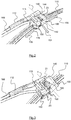
- the figure 2 represents the wiper system according to the invention in the operating position, the wiper 110 being connected to the arm 112 and locked relative thereto.
- the Figures 3 to 5 represent, in this order, steps of disassembly of the arm broom, for example for the replacement of the blade by a nine for example.
- the wiper blade 110 is rotated about the Y axis with respect to the drive arm 112 (arrow 180), so as to move it away from the tab 172 of the arm, and up to that the rim 176 of this tab is no longer opposite the lateral flank 142 of the cover and can therefore no longer cooperate with it.
- the swivel angle of the blade can be of the order of 20 ° to 40 °.
- the cover 140 which is integral with the connector 124, follows the movement of the blade on the glass surface.
- the pipe 160 is flexible and allows the pivoting of the cover 140 by deforming elastically.
- the wiper 110 is moved in translation along the Y axis away from the arm 112 (arrow 182), and until the shaft 170 on the drive arm 112 is removed from the housing 130 located on the connector 124 of the wiper blade 110.
- the distance of this movement is in particular a function of the length of the shaft 170.
- the brush 110 previously disassembled or a new broom may be mounted on the arm 112 by repeating the above operations in the opposite direction. More specifically, the connector 124 of the blade is engaged in the interior volume of the hood 140, by axial translation of the blade towards the hood 140 in a direction substantially perpendicular to the longitudinal axis of the drive arm.
- the cover 140 covers the connector 124 of the brush 110.
- the shaft 170 of the drive arm 112 is engaged in the housing 130 of the connector 124 by axial translation of the blade along the Y axis to the drive arm 112 , until the cover 140 bears laterally via its side flank 142 having the passage opening of the shaft 170, on the side face 178 of the arm 112.
- the wiper 110 is then moved in rotation around the Y axis ( figure 3 ), until the wall 144 of the hood bears on the transverse tab 172.
- the abutment flange 176 of the transverse tab 172 locks the cover 140 and therefore the blade 110 with respect to the drive arm 112, along the Y axis.
- the cover 140 can then be attached to the connector 124 , especially by clipping on the latter.
- the connecting piece 23 is integral with the connector 124 of the wiper blade 110.
- FIGS 6, 7A and 7B represent an alternative embodiment of the invention which comprises, in addition to the features described in the foregoing with reference to Figures 2 to 5 , means 25 for retaining the connecting piece 23 on the drive arm.
- These holding means 25 can be carried by the connecting piece 23 and are intended to cooperate with the arm 112.
- These retaining means 25 can also be carried by the drive arm 112 and are intended to cooperate with the connecting piece 23.
- the retaining means 25 may be integral with the connecting piece 23 or with the drive arm 112.
- These retaining means here comprise a side tab 190.
- the side tab 190 is carried by the cover 140 at a longitudinal end thereof.
- the side tab 190 extends here to a side of the cover 140 substantially in the extension of an end flank 146 thereof.
- the lateral lug 190 is parallel, or substantially parallel, to this end flank 146 and is therefore substantially parallel to the shaft 170 of the arm 112 and to the Y axis of rotation of the cap 140 with respect to the arm 112. , in mounting position.
- the side tab 190 emerges from the longitudinal end of the cover 140 which is intended to be located at the free end of the arm 112, when the cover 140 is in the operating position shown in FIG. figure 6 . In this position, the lateral tab 190 extends forward (or outside) of the free end of the arm 112.
- This free end of the arm 112 has an inverted U-shaped section and comprises two side walls 194 substantially parallel and interconnected by an upper wall 196.
- Side tab 190 is generally L-shaped and has a first wall 191 and a second wall 192 forming a stop.
- the second wall 192 forms for example a right angle with the first wall 191.
- the stop formed by the second wall 192 is intended to cooperate with the end of the arm 112.
- the second wall 192 is thus configured to abut on an internal lateral face of a side wall 194 of the arm, as can be seen in FIG. Figure 7B .
- This contact makes it possible to limit translational movement of the cover 140 along the Y axis with respect to the arm 112.
- This displacement is thus defined on the one hand by this cooperation between the second wall 192 of the side lug 190 and the arm 112 and on the other hand by the abutment of the cap 140 on the side wall 194 of the arm 112 .
- the first wall 191 of the side lug 190 has a length A always less than a length B corresponding to a free length of the shaft 170 on which the cover 140 can be inserted.
- the length A of the wall 191 is such that it allows in all cases to prevent the cover 140 from separating from the drive arm 112.
- the length A of the first wall 191 and the length B of the 170 are measured along directions parallel to each other.
- the second wall 192 is configured to rub on a lower face of the wall 196 of the arm 112 during its translational movement. This makes it possible to limit the rotational stroke of the cover 140 around the Y axis vis-à-vis the arm during the disassembly phase of the wiper blade.
- the rotational stroke is thus defined on the one hand by this cooperation between the second wall 192 of the side lug 190 and the arm 112 and on the other hand by the cooperation of the upper wall 144 of the hood with the transverse lug 172 carried by the arm 112.
- the transverse tabs 172 and side 190 may allow an angular deflection of 90 ° for example around the axis Y, when the holding means 25 is inactive. More precisely, the angular clearance allowed by the lateral lug 190 is greater than the minimum angular displacement necessary to allow the release of the hood 140 with respect to the transverse lug 172.
- the operating position of the hood 140 shown in figure 6 corresponds to that represented in figure 2 .
- the position of the hood 140 shown in the view of the Figure 7A corresponds to that represented in figure 3 wherein the cover 140 has been rotated about the Y axis, the flange 192 of the tab 190 being supported on the underside of the wall 196 of the arm 112.
- the position of the hood 140 shown in the view of the Figure 7B corresponds to that represented in figure 4 , in which the hood is remote from the arm and the wiper blade has been removed.
- the shaft 170 leaves free the inner volume 198 of the cover 140 and thus allows the insertion of the connector 124 of the blade in this inner volume 198, or its removal.
Landscapes
- Engineering & Computer Science (AREA)
- Mechanical Engineering (AREA)
- Water Supply & Treatment (AREA)
- Pivots And Pivotal Connections (AREA)
- Cleaning In General (AREA)
Applications Claiming Priority (1)
| Application Number | Priority Date | Filing Date | Title |
|---|---|---|---|
| FR1653279A FR3050158B1 (fr) | 2016-04-13 | 2016-04-13 | Systeme d’essuyage d’un pare-brise de vehicule |
Publications (1)
| Publication Number | Publication Date |
|---|---|
| EP3231673A1 true EP3231673A1 (de) | 2017-10-18 |
Family
ID=57113422
Family Applications (1)
| Application Number | Title | Priority Date | Filing Date |
|---|---|---|---|
| EP17162609.6A Withdrawn EP3231673A1 (de) | 2016-04-13 | 2017-03-23 | Reinigungssystem der windschutzscheibe eines fahrzeugs |
Country Status (4)
| Country | Link |
|---|---|
| US (1) | US20170297534A1 (de) |
| EP (1) | EP3231673A1 (de) |
| CN (1) | CN107444350A (de) |
| FR (1) | FR3050158B1 (de) |
Cited By (3)
| Publication number | Priority date | Publication date | Assignee | Title |
|---|---|---|---|---|
| WO2019120685A1 (de) * | 2017-12-19 | 2019-06-27 | Robert Bosch Gmbh | Scheibenwischervorrichtung |
| DE102019208390A1 (de) * | 2019-06-07 | 2020-12-10 | Robert Bosch Gmbh | Scheibenwischervorrichtung |
| WO2021032336A1 (de) * | 2019-08-22 | 2021-02-25 | Robert Bosch Gmbh | Wischervorrichtung UND SCHEIBENWISCHERSYSTEM MIT ZUMINDEST EINER WISCHERVORRICHTUNG |
Families Citing this family (4)
| Publication number | Priority date | Publication date | Assignee | Title |
|---|---|---|---|---|
| DE102018251764A1 (de) | 2018-12-28 | 2020-07-02 | Robert Bosch Gmbh | Wischarm mit Verbindungsadapter |
| DE102019204193A1 (de) * | 2019-03-27 | 2020-10-01 | Robert Bosch Gmbh | Scheibenwischervorrichtung mit einer Scheibenwasserverteilung |
| DE102019212251A1 (de) * | 2019-08-15 | 2021-02-18 | Robert Bosch Gmbh | Scheibenwischervorrichtung und Scheibenwischer mit einer Scheibenwischervorrichtung |
| FR3106548B1 (fr) * | 2020-01-28 | 2022-10-28 | Valeo Systemes Dessuyage | Essuyage pour petite surface |
Citations (3)
| Publication number | Priority date | Publication date | Assignee | Title |
|---|---|---|---|---|
| DE102005060617A1 (de) * | 2005-12-19 | 2007-06-28 | Volkswagen Ag | Scheibenwischeranlage für ein Fahrzeug |
| DE102012210167A1 (de) * | 2012-06-18 | 2013-12-19 | Robert Bosch Gmbh | Wischarmvorrichtung |
| FR3025473A1 (fr) * | 2014-09-08 | 2016-03-11 | Peugeot Citroen Automobiles Sa | Essuie-glace comportant un axe muni d'un gicleur |
Family Cites Families (6)
| Publication number | Priority date | Publication date | Assignee | Title |
|---|---|---|---|---|
| US2902063A (en) * | 1957-06-10 | 1959-09-01 | Roland R Keesee | Collapsible tube container and dispenser |
| JP2005059651A (ja) * | 2003-08-08 | 2005-03-10 | Asmo Co Ltd | 車両用ウォッシャノズル及び車両用ウォッシャ装置 |
| DE102006013900A1 (de) * | 2006-03-25 | 2007-09-27 | Valeo Systèmes d`Essuyage | Wischblatt |
| EP1847425B1 (de) * | 2006-04-21 | 2009-11-25 | Federal-Mogul S.A. | Scheibenwischervorrichtung |
| DE102009000860A1 (de) * | 2009-02-13 | 2010-08-19 | Robert Bosch Gmbh | Wischblatt mit einer Adaptereinheit zur Befestigung an einem Wischraum |
| CN105459962B (zh) * | 2014-06-06 | 2020-07-31 | 罗伯特·博世有限公司 | 刮水板 |
-
2016
- 2016-04-13 FR FR1653279A patent/FR3050158B1/fr not_active Expired - Fee Related
-
2017
- 2017-03-23 EP EP17162609.6A patent/EP3231673A1/de not_active Withdrawn
- 2017-04-12 US US15/485,632 patent/US20170297534A1/en not_active Abandoned
- 2017-04-13 CN CN201710239077.8A patent/CN107444350A/zh active Pending
Patent Citations (3)
| Publication number | Priority date | Publication date | Assignee | Title |
|---|---|---|---|---|
| DE102005060617A1 (de) * | 2005-12-19 | 2007-06-28 | Volkswagen Ag | Scheibenwischeranlage für ein Fahrzeug |
| DE102012210167A1 (de) * | 2012-06-18 | 2013-12-19 | Robert Bosch Gmbh | Wischarmvorrichtung |
| FR3025473A1 (fr) * | 2014-09-08 | 2016-03-11 | Peugeot Citroen Automobiles Sa | Essuie-glace comportant un axe muni d'un gicleur |
Cited By (6)
| Publication number | Priority date | Publication date | Assignee | Title |
|---|---|---|---|---|
| WO2019120685A1 (de) * | 2017-12-19 | 2019-06-27 | Robert Bosch Gmbh | Scheibenwischervorrichtung |
| US11524658B2 (en) | 2017-12-19 | 2022-12-13 | Robert Bosch Gmbh | Windshield wiper device |
| DE102019208390A1 (de) * | 2019-06-07 | 2020-12-10 | Robert Bosch Gmbh | Scheibenwischervorrichtung |
| US11541848B2 (en) | 2019-06-07 | 2023-01-03 | Robert Bosch Gmbh | Wiper arrangement |
| WO2021032336A1 (de) * | 2019-08-22 | 2021-02-25 | Robert Bosch Gmbh | Wischervorrichtung UND SCHEIBENWISCHERSYSTEM MIT ZUMINDEST EINER WISCHERVORRICHTUNG |
| US11772611B2 (en) | 2019-08-22 | 2023-10-03 | Robert Bosch Gmbh | Wiper device and windscreen wiper system having at least one wiper device |
Also Published As
| Publication number | Publication date |
|---|---|
| FR3050158B1 (fr) | 2019-08-09 |
| CN107444350A (zh) | 2017-12-08 |
| FR3050158A1 (fr) | 2017-10-20 |
| US20170297534A1 (en) | 2017-10-19 |
Similar Documents
| Publication | Publication Date | Title |
|---|---|---|
| FR3050158B1 (fr) | Systeme d’essuyage d’un pare-brise de vehicule | |
| EP2740638A1 (de) | Trägerelement, Haltevorrichtung eines Schlauchs, insbesondere für Fensterreinigungsflüssigkeit, und entsprechendes Reinigungssystem | |
| EP3165416B1 (de) | Adapter für ein kraftfahrzeugwischerblatt | |
| WO2013186503A1 (fr) | Balai d'essuyage a connecteur hydraulique | |
| EP3184379B1 (de) | Kappe und antriebsarm für eine reinigungsvorrichtung eines kraftfahrzeugs | |
| EP2707258B1 (de) | Flüssigsprühvorrichtung für ein wischblatt | |
| EP2692598B1 (de) | Verbindungsvorrichtung zwischen einem Wischerarm und einem Scheibenwischerelement | |
| EP2965958B1 (de) | Einheit aus einem mechanischen anschluss und einer kanüle für ein scheibenwischerblatt eines fahrzeugs | |
| EP2900525B1 (de) | Vorrichtung zur betätigung eines antriebsarms eines scheibenwischers, insbesondere für die heckscheibe eines kraftfahrzeuges, und wischsystem mit einer solchen vorrichtung | |
| EP3170709A1 (de) | Adapter, anschlussstück und einheit aus einem solchen anschlussstück und einem solchen adapter für einen scheibenwischer | |
| EP2965957B1 (de) | Schwenkbares verbindungselement für ein scheibenwischerblatt eines fahrzeugs | |
| EP3165417B1 (de) | Adapter für ein kraftfahrzeugwischerblatt | |
| EP3381754B1 (de) | Kappe und scheibenwischerarm für kraftfahrzeug | |
| EP3012163B1 (de) | Vorrichtung zum spritzen von scheibenwaschflüssigkeit für einen scheibenwischerarm des scheibenwischersystems eines fahrzeugs | |
| EP4448344A1 (de) | Endkappe und scheibenwischer für ein kraftfahrzeug | |
| FR3027268A1 (fr) | Dispositif de connexion entre un bras et un balai d'essuie-glace | |
| FR3031949A1 (fr) | Organe longitudinal pour un balai d'essuie-glace | |
| EP4188757B1 (de) | Verbinder für ein wischblatt | |
| WO2022175417A1 (fr) | Système de connexion d'un balai d'essuyage sur un bras d'un système d'essuyage | |
| FR3064961A1 (fr) | Bras d'entrainement et ensemble pour un dispositif d'essuyage pour vehicule automobile | |
| EP3192712B1 (de) | Adapter zum verbinden eines scheibenwischers mit einem antriebsarm | |
| EP3402703B1 (de) | Adapter zum anschliessen eines wischblatts an einem antriebsarm | |
| FR3030410A1 (fr) | Capot pour un bras d'essuie-glace | |
| FR3126378A1 (fr) | Adaptateur d’un système d’essuyage | |
| WO2021130023A1 (fr) | Système d'essuyage pour véhicule automobile |
Legal Events
| Date | Code | Title | Description |
|---|---|---|---|
| PUAI | Public reference made under article 153(3) epc to a published international application that has entered the european phase |
Free format text: ORIGINAL CODE: 0009012 |
|
| STAA | Information on the status of an ep patent application or granted ep patent |
Free format text: STATUS: REQUEST FOR EXAMINATION WAS MADE |
|
| 17P | Request for examination filed |
Effective date: 20170323 |
|
| AK | Designated contracting states |
Kind code of ref document: A1 Designated state(s): AL AT BE BG CH CY CZ DE DK EE ES FI FR GB GR HR HU IE IS IT LI LT LU LV MC MK MT NL NO PL PT RO RS SE SI SK SM TR |
|
| AX | Request for extension of the european patent |
Extension state: BA ME |
|
| R17P | Request for examination filed (corrected) |
Effective date: 20170323 |
|
| GRAP | Despatch of communication of intention to grant a patent |
Free format text: ORIGINAL CODE: EPIDOSNIGR1 |
|
| STAA | Information on the status of an ep patent application or granted ep patent |
Free format text: STATUS: GRANT OF PATENT IS INTENDED |
|
| INTG | Intention to grant announced |
Effective date: 20201012 |
|
| STAA | Information on the status of an ep patent application or granted ep patent |
Free format text: STATUS: THE APPLICATION IS DEEMED TO BE WITHDRAWN |
|
| 18D | Application deemed to be withdrawn |
Effective date: 20210223 |