EP3233348B1 - Systèmes et procédés pour mesures de capteur à semi-conducteur de câbles de soudage - Google Patents
Systèmes et procédés pour mesures de capteur à semi-conducteur de câbles de soudage Download PDFInfo
- Publication number
- EP3233348B1 EP3233348B1 EP15797539.2A EP15797539A EP3233348B1 EP 3233348 B1 EP3233348 B1 EP 3233348B1 EP 15797539 A EP15797539 A EP 15797539A EP 3233348 B1 EP3233348 B1 EP 3233348B1
- Authority
- EP
- European Patent Office
- Prior art keywords
- welding
- magnetic field
- weld cable
- tone
- field sensor
- Prior art date
- Legal status (The legal status is an assumption and is not a legal conclusion. Google has not performed a legal analysis and makes no representation as to the accuracy of the status listed.)
- Active
Links
- 238000003466 welding Methods 0.000 title claims description 247
- 238000000034 method Methods 0.000 title claims description 69
- 239000007787 solid Substances 0.000 title claims description 52
- 238000005259 measurement Methods 0.000 title claims description 12
- 230000008569 process Effects 0.000 claims description 33
- 238000004891 communication Methods 0.000 claims description 15
- 238000012512 characterization method Methods 0.000 claims description 8
- 230000005355 Hall effect Effects 0.000 claims description 3
- 230000004907 flux Effects 0.000 claims description 3
- 230000026676 system process Effects 0.000 claims 1
- 230000006870 function Effects 0.000 description 38
- 239000007789 gas Substances 0.000 description 15
- 230000036962 time dependent Effects 0.000 description 15
- 238000003860 storage Methods 0.000 description 10
- 238000004458 analytical method Methods 0.000 description 9
- 230000004044 response Effects 0.000 description 7
- 239000013598 vector Substances 0.000 description 7
- 238000010586 diagram Methods 0.000 description 6
- 230000005540 biological transmission Effects 0.000 description 5
- 238000006243 chemical reaction Methods 0.000 description 5
- 230000000875 corresponding effect Effects 0.000 description 5
- 239000002184 metal Substances 0.000 description 5
- 229910052751 metal Inorganic materials 0.000 description 5
- 238000009795 derivation Methods 0.000 description 4
- 238000012545 processing Methods 0.000 description 4
- 238000012546 transfer Methods 0.000 description 4
- 238000012937 correction Methods 0.000 description 3
- 125000004122 cyclic group Chemical group 0.000 description 3
- 239000000945 filler Substances 0.000 description 3
- 238000010438 heat treatment Methods 0.000 description 3
- 239000011159 matrix material Substances 0.000 description 3
- 230000010363 phase shift Effects 0.000 description 3
- XKRFYHLGVUSROY-UHFFFAOYSA-N Argon Chemical compound [Ar] XKRFYHLGVUSROY-UHFFFAOYSA-N 0.000 description 2
- CURLTUGMZLYLDI-UHFFFAOYSA-N Carbon dioxide Chemical compound O=C=O CURLTUGMZLYLDI-UHFFFAOYSA-N 0.000 description 2
- 230000009286 beneficial effect Effects 0.000 description 2
- 230000001419 dependent effect Effects 0.000 description 2
- 230000007613 environmental effect Effects 0.000 description 2
- 230000006698 induction Effects 0.000 description 2
- 239000011261 inert gas Substances 0.000 description 2
- 238000012360 testing method Methods 0.000 description 2
- 241000272470 Circus Species 0.000 description 1
- 230000004913 activation Effects 0.000 description 1
- 229910052786 argon Inorganic materials 0.000 description 1
- 239000010953 base metal Substances 0.000 description 1
- 239000003990 capacitor Substances 0.000 description 1
- 229910002092 carbon dioxide Inorganic materials 0.000 description 1
- 239000001569 carbon dioxide Substances 0.000 description 1
- 230000023402 cell communication Effects 0.000 description 1
- 230000001276 controlling effect Effects 0.000 description 1
- 230000002596 correlated effect Effects 0.000 description 1
- 230000008878 coupling Effects 0.000 description 1
- 238000010168 coupling process Methods 0.000 description 1
- 238000005859 coupling reaction Methods 0.000 description 1
- 230000000694 effects Effects 0.000 description 1
- 239000001307 helium Substances 0.000 description 1
- 229910052734 helium Inorganic materials 0.000 description 1
- SWQJXJOGLNCZEY-UHFFFAOYSA-N helium atom Chemical compound [He] SWQJXJOGLNCZEY-UHFFFAOYSA-N 0.000 description 1
- 238000011065 in-situ storage Methods 0.000 description 1
- 238000012880 independent component analysis Methods 0.000 description 1
- 230000007246 mechanism Effects 0.000 description 1
- 230000003287 optical effect Effects 0.000 description 1
- 230000000704 physical effect Effects 0.000 description 1
- 238000000513 principal component analysis Methods 0.000 description 1
- 230000001105 regulatory effect Effects 0.000 description 1
- 238000000926 separation method Methods 0.000 description 1
- WFKWXMTUELFFGS-UHFFFAOYSA-N tungsten Chemical compound [W] WFKWXMTUELFFGS-UHFFFAOYSA-N 0.000 description 1
- 239000010937 tungsten Substances 0.000 description 1
- 229910052721 tungsten Inorganic materials 0.000 description 1
Images


Classifications
-
- B—PERFORMING OPERATIONS; TRANSPORTING
- B23—MACHINE TOOLS; METAL-WORKING NOT OTHERWISE PROVIDED FOR
- B23K—SOLDERING OR UNSOLDERING; WELDING; CLADDING OR PLATING BY SOLDERING OR WELDING; CUTTING BY APPLYING HEAT LOCALLY, e.g. FLAME CUTTING; WORKING BY LASER BEAM
- B23K9/00—Arc welding or cutting
- B23K9/095—Monitoring or automatic control of welding parameters
- B23K9/0953—Monitoring or automatic control of welding parameters using computing means
-
- H—ELECTRICITY
- H04—ELECTRIC COMMUNICATION TECHNIQUE
- H04B—TRANSMISSION
- H04B3/00—Line transmission systems
- H04B3/54—Systems for transmission via power distribution lines
-
- B—PERFORMING OPERATIONS; TRANSPORTING
- B23—MACHINE TOOLS; METAL-WORKING NOT OTHERWISE PROVIDED FOR
- B23K—SOLDERING OR UNSOLDERING; WELDING; CLADDING OR PLATING BY SOLDERING OR WELDING; CUTTING BY APPLYING HEAT LOCALLY, e.g. FLAME CUTTING; WORKING BY LASER BEAM
- B23K9/00—Arc welding or cutting
- B23K9/095—Monitoring or automatic control of welding parameters
- B23K9/0956—Monitoring or automatic control of welding parameters using sensing means, e.g. optical
-
- B—PERFORMING OPERATIONS; TRANSPORTING
- B23—MACHINE TOOLS; METAL-WORKING NOT OTHERWISE PROVIDED FOR
- B23K—SOLDERING OR UNSOLDERING; WELDING; CLADDING OR PLATING BY SOLDERING OR WELDING; CUTTING BY APPLYING HEAT LOCALLY, e.g. FLAME CUTTING; WORKING BY LASER BEAM
- B23K9/00—Arc welding or cutting
- B23K9/10—Other electric circuits therefor; Protective circuits; Remote controls
- B23K9/1006—Power supply
- B23K9/1043—Power supply characterised by the electric circuit
- B23K9/1056—Power supply characterised by the electric circuit by using digital means
- B23K9/1062—Power supply characterised by the electric circuit by using digital means with computing means
-
- H—ELECTRICITY
- H04—ELECTRIC COMMUNICATION TECHNIQUE
- H04B—TRANSMISSION
- H04B2203/00—Indexing scheme relating to line transmission systems
- H04B2203/54—Aspects of powerline communications not already covered by H04B3/54 and its subgroups
- H04B2203/5429—Applications for powerline communications
- H04B2203/5458—Monitor sensor; Alarm systems
Definitions
- the present disclosure relates generally to welding systems and, more particularly, to systems and methods for solid state sensors for welding cable measurements.
- Welding is a process that has become increasingly prevalent in various industries and applications. Such processes may be automated in certain contexts, although a large number of applications continue to exist for manual welding applications. In both cases, such welding applications rely on a variety of types of equipment to ensure that the supply of welding consumables (e.g., wire, shielding gas, etc.) is provided to the weld in an appropriate amount at the desired time.
- welding consumables e.g., wire, shielding gas, etc.
- MIG metal inert gas
- welding typically relies on a wire feeder to enable a welding wire to reach a welding torch. The wire is continuously fed during welding to provide filler metal.
- a welding power source ensures that arc heating is available to melt the filler metal and the underlying base metal.
- power cables supply power from the welding power source to a welding torch performing a welding application.
- the welding power source may provide a welding voltage and current that may be utilized between the welding torch and a workpiece to perform the welding application.
- the arrangement and characteristics of power cables within the welding system may cause various distortions within the weld cable system that influence the welding process voltage and current. It may be beneficial to provide for systems and methods that efficiently and accurately compensate for distortions within the weld cable system and that provide for improved welding cable measurement systems.
- a remote control unit of an arc welding system is known.
- the remote control unit is located at a power source and includes a capacitor operable in response to closing of a gun switch to place an override current on the welding cables, and sensing means operable in response to such an override current to affect closing of a power source contactor to supply welding current to electrode and ground welding cables.
- the techniques described herein improve measurement and control of voltages and currents used in welding equipment, such as equipment used in welding, cutting, grinding, induction heating, testing, and so on.
- the welding equipment may more precisely operate at certain voltages and currents, for example, by providing for desired waveforms used in more precisely controlling a welding arc.
- impedance of the welding cable may alter the welding power delivered to the workpiece such that it is significantly different than the welding power, for example, at terminal outputs of the welding power supply.
- the techniques described herein provide for a solid state magnetic field sensor and for techniques suitable for more precisely measuring current close to or on a welding torch.
- the solid state magnetic field sensor may be combined with signal processing (e.g., digital signal processing [DSP]) techniques to calibrate sensor drift, to null ambient fields to facilitate welding, to provide for gain compensation, and/or to subtract contributions of stray magnetic fields from adjacent welding processes, thus improving welding equipment control and work quality.
- the solid state magnetic field sensor may be combined with certain techniques provided by weld cable communications (WCC) circuitry suitable for communications via a weld cable and also suitable for characterizing the weld cable. That is, certain characteristics of a specific weld cable may be derived by the WCC circuitry, such as impedance, resistance, and the like, that may result in power supplied by the welding power supply being slightly different than power being applied to the workpiece.
- WCC derivations may be compared with measurements obtained via the solid state magnetic field sensor to further adjust the WCC and/or welding power supply, thus improving welding operations.
- FIG. 1 is a block diagram of an embodiment of a welding system 10 having a welding power supply 12, a wire feeder 14, and a welding torch 16.
- the welding system 10 powers, controls, and supplies consumables to a welding application.
- the welding power source 12 directly supplies input power to the welding torch 16.
- the welding torch 16 may be a torch configured for stick welding, tungsten inert gas (TIG) welding, or gas metal arc welding (GMAW), based on the desired welding application.
- the welding power source 12 is configured to supply power to the wire feeder 14, and the wire feeder 14 may be configured to route the input power to the welding torch 16.
- the wire feeder 14 may supply a filler metal to a welding torch 14 for various welding applications (e.g., GMAW welding, flux core arc welding (FCAW)).
- GMAW flux core arc welding
- the welding power supply 12 receives primary power 18 (e.g., from the AC power grid, an engine/generator set, a battery, or other energy generating or storage devices, or a combination thereof), conditions the primary power, and provides an output power to one or more welding devices in accordance with demands of the system 10.
- the primary power 18 may be supplied from an offsite location (e.g., the primary power may originate from the power grid).
- the welding power supply 12 includes power conversion circuitry 20 that may include circuit elements such as transformers, rectifiers, switches, and so forth, capable of converting the AC input power to AC or DC output power as dictated by the demands of the system 10 (e.g., particular welding processes and regimes).
- the power conversion circuitry 20 may be configured to convert the primary power 18 to both weld and auxiliary power outputs. However, in other embodiments, the power conversion circuitry 20 may be adapted to convert primary power only to a weld power output, and a separate auxiliary converter may be provided to convert primary power to auxiliary power. Still further, in some embodiments, the welding power supply 12 may be adapted to receive a converted auxiliary power output directly from a wall outlet. Indeed, any suitable power conversion system or mechanism may be employed by the welding power supply 12 to generate and supply both weld and auxiliary power.
- the welding power supply 12 includes control circuitry 22 to control the operation of the welding power supply 12.
- the welding power supply 12 also includes a user interface 24.
- the control circuitry 22 may receive input from the user interface 24 through which a user may choose a process and input desired parameters (e.g., voltages, currents, particular pulsed or non-pulsed welding regimes, and so forth).
- the user interface 24 may receive inputs using any input device, such as via a keypad, keyboard, buttons, touch screen, voice activation system, wireless device, etc.
- the control circuitry 22 may control operating parameters based on input by the user as well as based on other current operating parameters.
- the user interface 24 may include a display 26 for presenting, showing, or indicating, information to an operator.
- the control circuitry 22 may also include interface circuitry for communicating data to other devices in the system 10, such as the wire feeder 14.
- the welding power supply 12 may wirelessly communicate with other welding devices within the welding system 10.
- the welding power supply 12 may communicate with other welding devices using a wired connection, such as by using a network interface controller (NIC) to communicate data via a network (e.g., ETHERNET, 10baseT, 10base100, etc.).
- NIC network interface controller
- the control circuitry 22 may communicate and interact with weld cable communications (WCC) circuitry 28, as further described in detail below.
- WCC weld cable communications
- the control circuitry 22 includes at least one controller or processor 30 that controls the operations of the welding power supply 12, and may be configured to receive and process multiple inputs regarding the performance and demands of the system 10.
- the processor 30 may include one or more microprocessors, such as one or more "general-purpose" microprocessors, one or more special-purpose microprocessors and/or ASICS, or some combination thereof.
- the processor 30 may include one or more digital signal processors (DSPs).
- DSPs digital signal processors
- the control circuitry 22 may include a storage device 32 and a memory device 34.
- the storage device 32 (e.g., nonvolatile storage) may include ROM, flash memory, a hard drive, or any other suitable optical, magnetic, or solid-state storage medium, or a combination thereof.
- the storage device 32 may store data (e.g., data corresponding to a welding application), instructions (e.g., software or firmware to perform welding processes), and any other suitable data.
- data that corresponds to a welding application may include an attitude (e.g., orientation) of a welding torch, a distance between the contact tip and a workpiece, a voltage, a current, welding device settings, and so forth.
- the memory device 34 may include a volatile memory, such as random access memory (RAM), and/or a nonvolatile memory, such as read-only memory (ROM).
- RAM random access memory
- ROM read-only memory
- the memory device 34 may store a variety of information and may be used for various purposes.
- the memory device 34 may store processor-executable instructions (e.g., firmware or software) for the processor 30 to execute.
- processor-executable instructions e.g., firmware or software
- control regimes for various welding processes, along with associated settings and parameters may be stored in the storage device 32 and/or memory device 34, along with code configured to provide a specific output (e.g., initiate wire feed, enable gas flow, capture welding current data, detect short circuit parameters, determine amount of spatter) during operation.
- the welding power flows from the power conversion circuitry 20 through a weld cable 36 to the wire feeder 14 and the welding torch 16.
- welding data may be provided with the weld cable 36 such that welding power and weld data are provided and transmitted together over the weld cable system.
- the WCC circuitry 28 may be communicatively coupled to the weld cable 36 to communicate (e.g., send/receive) data over the weld cable 36.
- the WCC circuitry 28 may be implemented based on various types of power line communications methods and techniques.
- the WCC circuitry 28 may utilize IEEE standard P1901.2 to provide data communications over the weld cable 36.
- the weld cable 36 may be utilized to provide welding power from the welding power supply 12 to the wire feeder 14 and the welding torch 16. Furthermore, the weld cable 36 may also be utilized to transmit (and/or receive) data communications to the wire feeder 14 and the welding torch 16. In addition, the WCC circuitry 28 may be communicatively coupled to the weld cable 36, for example, via a cable data coupler 37, to characterize the weld cable 36, as described in more detail below.
- the WCC circuitry 28 includes one or more processors 30, a digital to analog convertor 38 (e.g. DAC 38, which may function as a transmitter), an analog to digital converter 40 (e.g., ADC 40, which may function as a receiver), and a filter function 42 (e.g., filter circuitry, digital filter function circuitry, filter function software executable by the one or more processors 30, or any combination thereof).
- a digital to analog convertor 38 e.g. DAC 38, which may function as a transmitter
- an analog to digital converter 40 e.g., ADC 40, which may function as a receiver
- a filter function 42 e.g., filter circuitry, digital filter function circuitry, filter function software executable by the one or more processors 30, or any combination thereof.
- the WCC circuitry 28 may be utilized to determine channel equalization filter coefficients representative of a distortive characteristic and/or a distortion related to a weld cable.
- the distortive characteristic may be a frequency and time dependent amplitude and phase distortion (e.g., amplitude and/or phase distortion that is both frequency dependent and time dependent), as further described with respect to FIGS. 2-3 .
- the WCC circuitry 28 may be configured to utilize the channel equalization filter coefficients to compensate for the distortive characteristic of the weld cable.
- the WCC circuitry 28 may include one or more processors 30 separate from the processors 30 of the control circuitry 22.
- the WCC circuitry 28 may utilize the processors 30 of the control circuitry 22.
- the WCC circuitry 28 may be incorporated within, or may be coupled to, the control circuitry 22.
- the DAC 38 may be coupled to the processor 30, and is configured to transmit data communications utilizing one or more carrier channels or "tones." Specifically, the one or more tones may be described as complex sinusoidal signals that are transmitted by the DAC 38. In certain embodiments, the DAC 38 may be disposed within the welding power supply 12, and the tones may be transmitted to one or more components of the welding system 10, such as to the welding torch 16 and/or the wire feeder 14. In other embodiments, the DAC 38 may be disposed within the welding torch 16, and the tones may be transmitted to the welding power supply 12 and/or the wire feeder 14.
- one or more components of the WCC circuitry 28 may be disposed anywhere within the welding system 10, such as within the wire feeder 14 and/or the welding torch 16.
- the DAC 38 may transmit modulated tones and/or unmodulated tones.
- Modulated tones may be utilized to communicate (e.g., send/receive) data using one or more known techniques for modulating a signal for data transmission.
- the DAC 38 may utilize a hybrid amplitude and phase modulation scheme, such as Bi-Phase Shift Keying (BPSK), Quadrature Phase Shift Keying (QPSK), 16-ary Quadrature Amplitude Shift Keying (16-QAM) or similar variations.
- BPSK Bi-Phase Shift Keying
- QPSK Quadrature Phase Shift Keying
- 16-QAM 16-ary Quadrature Amplitude Shift Keying
- the modulated tones transmitted may include any type of information useful for the welding process or operation.
- the data transmitted by the WCC circuitry 28 may include information related to any welding parameter (e.g., weld voltage, wire speed) that is transmitted to the wire feeder 14 and/or the welding torch 16 for
- the DAC 38 may also transmit unmodulated tones (also known as "pilot tones") that do not carry data.
- unmodulated tones may be sinusoidal signals that have predefined or known characteristics, such as a predefined amplitude, frequency and phase.
- the DAC 38 may transmit unmodulated tones having the same amplitude but a different frequency, which may be an integral multiple of a lower reference frequency and a phase offset value.
- modulated tones may be distinguishable from unmodulated tones based on their assigned frequency, or their position within an OFDM frame.
- the positional assignment of modulated versus unmodulated tones may be preassigned and this position may be known at the receiver (e.g., the ADC 40). Since the characteristics of the unmodulated tones are also known, unmodulated tones may be utilized as reference tones. In certain embodiments, a set of modulated tones with known characteristics may also be transmitted. For example, modulated tones with a known data modulation scheme, and a known (or predefined) data sequence may be transmitted in lieu of and/or along with the known unmodulated tones.
- the data sequence may be of the form of cyclic prefix within the OFDM frame, for example, such that the last N symbols of an OFDM frame are appended to the beginning of the frame.
- the receiver e.g., the ADC 40
- a circular convolution of the received frame may be performed and the results of that convolution may be used to compute the equivalent frequency and time dependent amplitude and phase distortion in the weld cable 36, and from that information a set of coefficients for a correcting channel equalization filter (e.g., an inverse function of the measured distortion) may be determined.
- a correcting channel equalization filter e.g., an inverse function of the measured distortion
- either a known modulated or a known unmodulated tone may be utilized as a reference.
- the DAC 38 may transmit a plurality of tones, any number of which may be modulated or unmodulated. For example, out of 64 tones transmitted by the DAC 38, 48 of the tones may be modulated tones utilized for data transmission and 16 tones may be unmodulated tones utilized as reference tones (without any data modulation). It should be noted that the DAC 38 may be configured to transmit any number of modulated tones and unmodulated tones.
- the ADC 40 of the WCC circuitry 28 may be configured to receive the several transmitted modulated and unmodulated tones, as described with respect to FIGS. 2-3 .
- the filter function 42 may be configured to process and analyze the received modulated and unmodulated tones to characterize the weld cable 36. More specifically, the filter function 42 of the WCC circuitry 28 may be configured to apply a digital filter function that is configured to compare the unmodulated tones transmitted by the DAC 38 with the unmodulated tones received by the ADC 40. In particular, based on the differences (if any) between the transmitted unmodulated signals and received unmodulated signals, the filter function 42 may be configured to determine one or more coefficients (e.g., values, polynomials, etc.).
- the one or more coefficients may correspond to distortion characteristics of the weld cable 36.
- the filter function 42 may be configured to utilize the determined coefficients to compensate for possible frequency and time dependent amplitude and phase distortion in the weld cable 36, as further described with respect to FIGS. 2-3 .
- the WCC circuitry 28 is configured to communicate with the control circuitry 22, which may be configured to adjust a welding voltage provided to the welding torch 16 (and/or to the wire feeder 14) based on information received from the filter function 42.
- the storage device 32 or the memory device 34 may be configured to store data related to the WCC circuitry 28, such as characteristics (e.g., a phase, an amplitude, a frequency) of each unmodulated tone transmitted or received by the WCC circuitry 28, information related to the frequency of each tone transmitted or received by the WCC circuitry 28, the number and/or grouping of the unmodulated or modulated tones, the one or more determined frequency and time dependent amplitude and phase distortions in the weld cable 36, the location of the DAC 38 and/or the ADC 40, the channel equalization filter coefficients calculated or determined by the WCC circuitry 28, a current, previous, actual, or corrected welding operating parameter (e.g., welding voltage, wire speed), and any other information related to the WCC circuitry 28.
- characteristics e.g., a phase, an amplitude, a frequency
- information related to the frequency of each tone transmitted or received by the WCC circuitry 28 the number and/or grouping of the unmodulated or modulated tones, the one or more
- the storage device 32 or the memory device 34 may be configured to store one or more templates of unmodulated (e.g., reference) or modulated tones that have known characteristics.
- the one or more templates may include 16 unmodulated tones each having a known amplitude, a known frequency, and a known phase shift.
- the WCC circuitry 28 may be configured to compare the received modulated or unmodulated tones with a corresponding template.
- One or more magnetic field solid state sensor(s) 44 provide for certain measurements at a weld cable 36 location close to the welding torch 16 and/or on the welding torch 16.
- the magnetic field solid state sensor(s) 44 may be disposed on the weld cable 36 proximate to the welding torch 16, such as a location approximately between 0 to 0.5 inches (i.e., less than approximately 0.5 inches), 0.25 to 1 inch, 0 to 5 inches (i.e., less than approximately 5 inches) or more from the welding torch 16 along a length of the weld cable 36.
- the magnetic field solid state sensor(s) 44 may include a microelectromechanical system (MEMS) suitable for converting a magnetic field to a signal, such as a voltage signal, representative of a magnetic field generated by current flowing through the weld cable 36 and detected by the magnetic field solid state sensor(s) 44.
- MEMS microelectromechanical system
- the voltage signal may then be processed, for example, by the ADC(s) 40 to convert the signal into data, such as a measurement of a magnetic field and/or measurement of a current.
- the data may be transmitted to the processor(s) 30, to derive a current being applied through the welding torch 16, as well as to derive certain welding curves (e.g., current curves, voltage curves) used in operations of the welding system 10.
- the magnetic field solid state sensor(s) 44 may include a 1-axis magnetic sensor disposed in a single chip, such as a magnetoresistive sensor model number HMC1061 available from Honeywell, of New Jersey, U.S.A. Additionally or alternatively, the magnetic field solid state sensor(s) 44 may include 2-axis and/or 3-axis sensors. Each axis may be orthogonal to the other axis or axes. Additionally, or alternatively, the magnetic field solid state sensor(s) 44 may include a Hall effect sensor, such as a transducer that varies its output voltage in response to a magnetic field through the Hall effect.
- a Hall effect sensor such as a transducer that varies its output voltage in response to a magnetic field through the Hall effect.
- magnétique field sensor types may be used, suitable for converting a magnetic field into a signal (e.g., voltage signal), including flux gate magnetometers.
- a signal e.g., voltage signal
- flux gate magnetometers e.g., flux gate magnetometers.
- the magnetic field solid state magnetic field sensor(s) 44 may advantageously provide for a suitable sensor for welding system applications, including welding, cutting, grinding, induction heating, testing, and the like.
- signals from the magnetic field solid state sensor(s) 44 may be transmitted to the ADC 40.
- the ADC 40 may be located in the wire feeder 14, in the welding power supply 12, and or in custom enclosures proximate to the magnetic field solid state sensor(s) 44.
- the ADC 40 may then convert magnetic field solid state sensor(s) 44 signals into digital data, and communicate the data to the processor(s) 30.
- the processor(s) 30 may be located in the wire feeder 14, in the welding power supply 12, and or in custom enclosures proximate to the magnetic field solid state sensor(s) 44. Signals from the magnetic field solid state sensor(s) 44 and data from the ADC 40 may be communicated using wired and/or wireless communication techniques.
- the weld cable 36 itself may be used to transmit signals and/or data from the magnetic field solid state sensor(s) 44 and the ADC 40.
- the WCC circuitry 28 disposed in the welding power supply 12 may communicate with other WCC circuitry 28 disposed, for example, at a weld cable 36 location close to the welding torch 16 (e.g., in the wire feeder 14) and communicatively coupled to the magnetic field solid state sensor 44. Any and all techniques used by the WCC circuitry to transmit via the transmitter 38 and to receive via the receiver 40 may be used.
- the WCC circuitry 28 may utilize IEEE standard P1901.2 to provide welding power and data communications over the weld cable 36.
- One or more carrier channels or "tones” may be used as describe above to send data between WCC circuitry 28.
- the tones may apply cell communication techniques (e.g., code division multiple access [CDMA], global system for mobile [GSM] communications), and the like.
- wireless systems e.g., WiFi, mesh network systems, RFC systems, Bluetooth systems, ZigBee, and the like
- Wired conduits between the welding power supply 12, the wire feeder 14, and/or the magnetic field solid state sensor(s) 44 may also be used for communication.
- the processor(s) 30 may receive signals from the magnetic field solid state sensor(s) 44 and/or data from the ADC 40 to derive, for example, the actual current being delivered during operations (e.g., through the weld cable 36 and/or at the welding torch 16), as opposed to the current being measured at the welding power supply 12.
- the processor(s) 30 may additionally compare certain characterizations of the weld cable 36 derived via the WCC circuitry 28 with data from the magnetic field solid state sensor(s) 44 to calibrate the WCC circuitry 28 and/or the welding power supply 12, as described in more detail below with respect to FIG. 4 .
- the processor(s) 30 may use magnetic field solid state sensor(s) 44 signals and/or data to recalibrate the magnetic field solid state sensor(s) 44.
- the processor(s) 30 may recalibrate sensor drift of the magnetic field solid state sensor(s) 44, apply the magnetic field solid state sensor(s) 44 to null ambient fields to facilitate welding, provide for gain compensation, and/or to subtract contributions of stray magnetic fields from adjacent welding processes, also as described in more detail below with respect to FIG. 4 .
- a gas supply 45 provides shielding gases, such as argon, helium, carbon dioxide, and so forth, depending upon the welding application.
- the shielding gas flows to a valve 46, which controls the flow of gas, and if desired, may be selected to allow for modulating or regulating the amount of gas supplied to a welding application.
- the valve 46 may be opened, closed, or otherwise operated by the control circuitry 22 to enable, inhibit, or control gas flow (e.g., shielding gas) through the valve 46.
- Shielding gas exits the valve 46 and flows through a cable 48 (which in some implementations may be packaged with the welding power output) to the wire feeder 14 which provides the shielding gas to the welding application.
- certain embodiments of the welding system 10 may not include the gas supply 45, the valve 46, and/or the cable 48.
- the wire feeder 14 may use the welding power to power the various components in the wire feeder 14, such as to power control circuitry 50.
- the weld cable 36 may be configured to provide or supply the welding power.
- the welding power supply 12 may also communicate with the wire feeder 14 using the weld cable 36 and the WCC circuitry 28 disposed within the welding power supply 12.
- the wire feeder 14 may include the WCC circuitry 28, which is substantially similar to the WCC circuitry 28 of the welding power supply 12. Indeed, the WCC circuitry 28 of the wire feeder 14 may cooperate with the control circuitry 50 of the wire feeder 14 in similar ways as the welding power supply 12 cooperates with the control circuitry 22.
- the control circuitry 50 controls the operations of the wire feeder 14.
- the wire feeder 14 may use the control circuitry 50 to detect whether the wire feeder 14 is in communication with the welding power supply 12 and to detect a current welding process of the welding power supply 12 if the wire feeder 14 is in communication with the welding power supply 12.
- a contactor 52 (e.g., high amperage relay) is controlled by the control circuitry 50 and configured to enable or inhibit welding power to continue to flow to the weld cable 36 for the welding application.
- the contactor 52 may be an electromechanical device, while in other embodiments the contactor 52 may be any other suitable device, such as a solid state device.
- the wire feeder 14 includes a wire drive 54 that receives control signals from the control circuit 50 to drive rollers 56 that rotate to pull wire off a spool 58 of wire. The wire is provided to the welding application through a wire cable 60. Likewise, the wire feeder 14 may provide the shielding gas through the cable 48.
- the cables 36, 48, and 60 may be bundled together or individually provided to the welding torch 16.
- the welding torch 16 delivers the wire, welding power, and shielding gas for a welding application.
- the welding torch 16 is used to establish a welding arc between the welding torch 16 and a workpiece 62.
- a work cable 64 which may be terminated with a clamp 65 (or another power connecting device), couples the welding power supply 12 to the workpiece 62 to complete a welding power circu it.
- FIG. 2 is a flow diagram of an embodiment of a method 66 for correcting a distortive characteristic of the weld cable 36 in the weld system 10, in accordance with aspects of the present disclosure.
- the distortive characteristic may be a frequency and time dependent amplitude and phase distortion of the weld cable 36.
- the distortive characteristic may be determined by determining one or more channel equalization filter coefficients. Further, the WCC circuitry 28 may compensate for the distortive characteristic by utilizing the determined channel equalization filter coefficients.
- the WCC circuitry 28 of the welding power supply 12 may be configured to characterize the parameters or properties of the weld cable 36 with one or more channel equalization filter coefficients.
- the one or more channel equalization filter coefficients may be values that are representative of various characteristics of the weld cable 36.
- the channel equalization filter coefficients may be representative of a distortive characteristic of the weld cable 36.
- the channel equalization filter coefficients may be representative of frequency and time dependent amplitude and phase distortions of the weld cable 36.
- the systems and methods described herein allow for the characterization of the weld cable 36, and obviate the need for taking actual measurements to characterize the weld cable 36, as further described in detail below.
- the one or more channel equalization filter coefficients may be utilized to compensate for frequency and time dependent amplitude and phase distortion within the weld cable 36 that may influence the power or data being transmitted. For example, certain embodiments address situations in which the welding voltage provided by the welding power supply 12 would be substantially different than the welding voltage received by the welding torch 16 due to frequency and time dependent amplitude and phase distortion in the weld cable 36 if not mitigated.
- the WCC circuitry 28 may be configured to determine one or more channel equalization filter coefficients that may be representative of distortion characteristics of the weld cable 36. Further, the WCC circuitry 28 may be configured to utilize the one or more channel equalization filter coefficients that are determined to compensate for any frequency and time dependent amplitude and phase distortion within the weld cable 36, as further described below.
- the method 66 begins with the WCC circuitry 28 transmitting modulated tones and unmodulated tones (block 68) from the welding power supply 12 and/or the wire feeder 14.
- the DAC 38 of the WCC circuitry 28 may be configured to transmit the modulated and unmodulated tones.
- modulated tones may include information related to the welding process or operation, such as information related to an operating parameter (e.g., weld voltage, wire speed, etc.) of the welding system 10 or related to an adjusted operating parameter of the welding system 10.
- unmodulated tones e.g., pilot tones transmitted by the DAC 38 may not carry any information related to the welding process or operation.
- unmodulated tones may be sinusoidal reference signals that have predefined or known characteristics, such as a predefined amplitude, frequency, and/or phase.
- all of the unmodulated tones transmitted may have the same frequency and amplitude.
- the modulated tones transmitted may also have known characteristics that allow the modulated tones to be utilized as the reference tones.
- the unmodulated tones may each be transmitted at a known phase. For example, each of the unmodulated tones transmitted may be equally spaced in tone frequency, such that each succeeding tone increments its phase reference to the first tone by 90 degrees.
- a first unmodulated tone is at a reference of 0 degrees of phase
- a second unmodulated tone may be at 90 degrees phase
- a third unmodulated tone may be at 180 degrees phase
- the unmodulated tones may be configured at any alternate unmodulated tone configuration, so long as the frequency, amplitude and phase configurations are known and substantially constant.
- the phase of each unmodulated tone need not be equally spaced, so long as the phase is known.
- the method 66 further includes the WCC circuitry 28 receiving the transmitted modulated and unmodulated tones at the ADC 40 (block 70).
- the WCC circuitry 28 may transmit the modulated tones and unmodulated tones to the welding torch 16 and may receive the transmitted tones from the welding torch 16.
- the WCC circuitry 28 may be configured to account or compensate for the distortion of the weld cable 36 twice and/or in two directions (e.g., a first distortion from the WCC circuitry 28 to the welding torch 16 and a second distortion from the welding torch 16 to the WCC circuitry 28).
- the welding torch 16 may include a DAC 38 that is configured to transmit the modulated and unmodulated tones.
- the WCC circuitry 28 may be configured to account or compensate or the distortion of the weld cable 36 once and/or in one direction.
- the ADC 40 may be configured to receive the modulated and unmodulated tones, and may also be configured to receive the original location from which the tones were transmitted.
- the ADC 40 may provide the received tones (e.g., modulated and unmodulated) to the filter function 42 for further processing.
- the method 66 includes applying a digital filter function to the received modulated and unmodulated tones with the filter function 42 (block 72).
- the digital filter function may be utilized to compare the transmitted unmodulated tones with the received unmodulated tones.
- the transmitted unmodulated tones are transmitted with a known amplitude, frequency, and phase. Accordingly, in certain embodiments, the transmitted unmodulated tones may be utilized as reference tones and compared with the received unmodulated tones within the filter function 42 to determine one or more differences, such as differences in phase, amplitude, or frequency.
- the filter function 42 may be configured to determine one or more channel equalization filter coefficients.
- the channel equalization filter coefficients may be representative of the distortive characteristics of the weld cable 36, as further described with respect to FIG. 3 .
- the method 66 includes compensating for the frequency and time dependent amplitude and phase distortion (e.g., distortive characteristic of the weld cable 36) utilizing the channel equalization filter coefficients (block 74).
- the WCC circuitry 28 may be configured to adjust one or more welding parameters based on the one or more determined coefficients and based on the characteristics of the weld cable 36. For example, in certain situations, the WCC circuitry 28 may increase or decrease a welding voltage provided by the welding power supply 12 to the wire feeder 14 and/or the welding torch 16 based on the calculated channel equalization filter coefficients. As a further example, the WCC circuitry 28 may be configured to increase or decrease a wire speed provided by the wire feeder 14 based on the calculated channel equalization filter coefficients.
- the WCC circuitry 28 provides this information to the control circuitry 22, so that the control circuitry 22 may make the proper adjustments to the welding parameters and/or provide the information to other components of the welding system 10.
- the WCC circuitry 28 may be configured to provide to the welding system 10 the determined and/or calculated distortive characteristics and/or coefficients of the weld cable 36. Accordingly, the calculated or determined distortive characteristics and/or coefficients may be provided by the control circuitry 22 as actual feedback to other components of the welding system 10.
- the method 66 may be utilized as a continuous feedback loop 75 that allows for the correction of power and data transmitted via the weld cable 36 in subsequent times based on the information calculated and determined.
- the WCC circuitry 28 may be configured to regulate and correct for any frequency and time dependent amplitude and phase distortion in the weld cable 36 in a dynamic process during the operation of the welding torch 16. Accordingly, more accurate welding operating parameters may be utilized during the welding process.
- the WCC circuitry 28 may dynamically adjust the welding voltage provided to the welding torch 16 and workpiece 62 during the welding process.
- FIG. 3 is a flow diagram of an embodiment of a method 76 for calculating the one or more channel equalization filter coefficients of FIG. 2 , in accordance with aspects of the present disclosure.
- the filter function 42 of the WCC circuitry 28 may be configured to apply a digital filter function to the modulated and unmodulated tones received by the ADC 40 and transmitted by the DAC 38.
- the filter function 42 may be configured to calculate or determine one or more channel equalization filter coefficients based on the modulated and unmodulated tones received by the ADC 40, as further described below.
- the method 76 begins with separating the unmodulated tones from the modulated tones received by the ADC 40 (block 78).
- the ADC 40 may receive 64 tones, of which 48 tones are modulated tones utilized for data transmission and 16 tones are unmodulated tones. Accordingly, the unmodulated tones may be separated from the modulated tones by the filter function 42 for further processing to determine the one or more coefficients.
- the method further includes compensating for timing and phasing of the unmodulated tones (block 80).
- the filter function 42 may be configured to compensate for the frequency error between the DAC 38 and the ADC 40 with one or more frequency and/or phase control loops.
- the ADC 40 may be configured to associate each transmitted tone with a corresponding received tone.
- 16 unmodulated tones may be transmitted by the DAC 38 with a known amplitude, a known frequency, and at a known phase shift. Accordingly, each of the 16 transmitted unmodulated tones may correspond to each of the 16 received unmodulated tones.
- compensating for frequency and phase may include associating the transmitted tone with its corresponding received tone.
- the method 76 may be configured to compensate and correct for the frequency variations between the DAC 38 and the ADC 40 before separating the modulated tones from the unmodulated tones.
- the method 76 may include measuring the characteristics (e.g., phase, amplitude and/or frequency) of the received unmodulated tones.
- the filter function 42 may be configured to measure the actual amplitude, and the actual phase of the received unmodulated tones (block 82).
- the transmitted unmodulated tones may be transmitted with a known frequency, a known amplitude, and a known phase and may thus be utilized as a reference tone.
- the method 76 may include comparing the characteristics of the received unmodulated tones with the characteristics of the transmitted (reference) unmodulated tones (block 84). Comparing the received unmodulated tones and the transmitted (reference) unmodulated tones may be done in any suitable manner.
- the received unmodulated tones are multiplied by the complex conjugate of the original transmitted (reference) unmodulated tones.
- the expected result of a vector multiplied by its complex conjugate is a vector with an amplitude and no imaginary part. In this case, the expected answer would be "1 + j0.”
- the error vector resulting from the multiplication of the complex conjugate of the received unmodulated tones and the original transmitted (reference) tones is utilized to perform an interpolation.
- the interpolation populates missing members of the set of tones, at each indexed frequency, with a phasor with an interpolated amplitude and an interpolated phase.
- the actual result of a vector multiplied by its complex conjugate indicates an amplitude and phase distortion for each tone.
- the actual answer is a series of vectors, each with amplitude and phase, for each pilot tone frequency.
- the actual result of the digital filter function process may be a 3 x 64 matrix with frequency, amplitude, and phase as column vectors and each of the 64 values assuming a row position.
- the 16 measured error vectors populate the positions in the 3 x 64 matrix assigned to the reference tones and the 48 'missing' tones, assigned to the data tones, are populated with interpolated values.
- the resulting 3 x 64 matrix is then used as the data to calculate the channel equalization filter and also the inverse of the channel equalization filter.
- Other reference tone versus data tone configurations, FFT lengths and OFDM symbol configurations are possible.
- the filter function 42 may be configured to utilize the differences determined between the received unmodulated tones and the transmitted (reference) unmodulated tones to determine the channel equalization filter coefficients (block 86).
- the channel equalization filter coefficients define a Finite Impulse Response (FIR) or Infinite Impulse Response (IIR) filter with a length that is determined by the number of tones used in the OFDM system, otherwise specified as the symbols in an OFDM frame, excluding any cyclic prefix, and which filter provides an inverse function to the frequency dependent amplitude and phase distortion of the weld cable 36.
- FIR Finite Impulse Response
- IIR Infinite Impulse Response
- the inverse of the channel equalization filter is the analytic description of the two port transfer function of the weld cable as a transmission line.
- the inverse of the channel equalization filter coefficients may be transformed, using a mathematical algorithm, to describe any characteristic or physical property of the weld cable 36 that may have an effect on the power or data transmitted by the weld cable 36.
- the transfer function (inverse channel equalization filter) may be representative of a length of the weld cable 36, a resistance, an inductance, and so forth.
- the inverse channel equalization filter (transfer function) is not the characteristic itself, but are merely an abstract representation of the characteristics as defined in a sampled time reference system.
- the method 76 further includes utilizing the channel equalization filter coefficients determined from the unmodulated tones pre-distort each of the modulated and unmodulated tones that will be transmitted by the DAC 38 in the next iteration of the function (block 88).
- the unmodulated tones may be multiplied with the modulated tones by the channel equalization (FIR) filter to correct for the frequency and time dependent amplitude and phase distortion of the weld cable 36 (e.g., distortive characteristic of the weld cable 36).
- FIR channel equalization
- the method 76 calculates the channel equalization filter and its inverse function.
- the inverse function of the channel equalization filter provides the equivalent two port transfer function of the weld cable and can be used as an element in the feedback loop within the welding power supply 12 control system, effectively replacing the voltage sense cable 92.
- FIG. 4 is a block diagram of an embodiment of the welding system 10 of FIG. 1 , illustrating the WCC circuitry 28 and the magnetic field solid state sensor(s) 44 communicatively coupled to the ADC 40, the one or more processor(s) 30 and to the weld cable 36.
- the magnetic field solid state sensor(s) 44 may transmit signals, such as voltage signals, to the ADC 40, which may then translate the signals into digital signals delivered to the processor(s) 30.
- the ADC 40 may be disposed, for example, in the wire feeder 14, in the welding power supply 12, and/or proximate to the magnetic field solid state sensor(s) 44.
- the depicted embodiment also shows the WCC circuitry 28 operatively coupled to the weld cable 36 via the cable data coupler 37.
- the cable data coupler 37 may be a non-intrusive coupling system that may be attached to the outside of the weld cable 36 and sense the weld cable's magnetic field. Additionally or alternatively, the cable data coupler 37 may pierce the weld cable 36 to sense current and/or voltage from the weld cable 36 and deliver the sensed data to the WCC circuitry 28.
- the welding power supply 12 provides a specific welding process power having a desired current profile and/or a desired waveform (e.g., current waveform, voltage waveform, and so forth).
- a desired current profile and/or a desired waveform e.g., current waveform, voltage waveform, and so forth
- information regarding the current profile and/or waveform is communicated to the WCC circuitry(s) 28 and/or stored by the processor(s) 30 (e.g., in the storage device 32 and/or the memory device 34).
- the communicated/stored data e.g., expected current profile and/or waveform
- the magnetic field solid state sensor(s) 44 may be used to observe deviations from the expected current.
- the processor(s) 30 may then derive and apply correction factors (e.g., gain compensation for current, voltage) to more closely deliver the desired current profile and/or waveform.
- correction factors e.g., gain compensation for current, voltage
- the magnetic field solid state sensor(s) 44 may be recalibrated via the processor(s) 30.
- the communicated/stored data becomes a template of a discrete time (sampled) function which may be transformed by a filter, such as a channel equalization filter, so as to better match the current as modified by the weld cable 36 (e.g., modified by weld cable 36 impedance).
- a filter such as a channel equalization filter
- the results of applying the filter and may then be correlated with data measured via the magnetic field solid state sensor(s) 44. Data that correlates well may then be separated and saved for further use. Residual data is likely noise and not used.
- the saved data may then be processed to derive and apply correction factors (e.g., gain compensation for current, voltage) to more closely deliver the desired current profile and/or waveform.
- the weld cable 36 and related grounds may be linear systems, and thus the theory of superposition holds such that a net response at a given place and time caused by two or more stimuli is the sum of the responses which would have been caused by each stimulus individually. That is, the myriad of combined signals on the weld cable 36 are likely a linear combination of separate time varying functions.
- DSP techniques may be used to separate out a know pattern (e.g., desired waveform).
- principal component analysis, independent component analysis, blind or near-blind signal separation analysis may be used to determine the actual signal delivered by the welding power supply 12 versus signals coming from neighboring welding power supplies 12.
- ambient fields may be nullified.
- the magnetic field solid state sensor(s) 44 may be used to derive stray ambient fields and, in certain embodiments, a field generator 47 may be used to generate an opposing magnetic field in a weld region, thus nullifying the ambient fields.
- the WCC circuitry 28 may be used to characterize the weld cable 36. Improvements to this characterization may be made by applying data received from the magnetic field solid state sensor(s) 44. For example, after characterizing the weld cable 36, the WCC circuitry 28 may be used to predict current at the location of the magnetic field solid state sensor(s) 44. This prediction may be validated by the magnetic field solid state sensor(s) 44, and any deviations may be used to adjust the WCC circuitry 28. Similarly, sensor drift, or calibration of the magnetic field solid state sensor(s) 44 may be provided.
- the magnetic field solid state sensor(s) 44 may be calibrated in situ to account for "drifting" of readings based on elapsed time and/or environmental conditions (e.g., temperature, pressure, and so forth). For example, data measured via the magnetic field solid state sensor(s) 44 may be logged and used to determine that one or more magnetic field solid state sensors 44 may be drifting over time, or based on certain environmental conditions. Logged data may show certain patterns, such as an increase in drift over time, different measurements based on differing temperatures, and so on. The one or more magnetic field solid state sensors 44 determined to be drifting may then be re-calibrated. Additionally, the WCC circuitry 28 may be used to communicate the magnetic field solid state sensor(s) 44 data, for example, from the wire feeder 14 to the power supply 12.
- environmental conditions e.g., temperature, pressure, and so forth.
- data measured via the magnetic field solid state sensor(s) 44 may be logged and used to determine that one or more magnetic field solid state sensors 44 may be drifting over time,
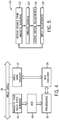
- FIG. 5 is a flowchart of an embodiment of a process 110 suitable for applying the magnetic field sensor(s) 44 and/or the WCC circuitry 28 to improve operations of the welding system 10.
- the process 110 may include receiving signals from the magnetic field solid state sensor(s) 44, for example, signals representative of the magnetic field at a location proximate to the welding torch 16 (block 112). The signals may be converted into digital data by the ADC 40.
- the process 110 may then include analyzing the received data (block 114), for example, to derive a magnetic field at the sensed location(s).
- the analysis (block 114) may also include deriving differences between expected current and/or waveforms and actual current and/or waveforms delivered to the workpiece 62.
- the analysis (block 114) may additionally include any and all derivations provided by the WCC circuitry 28, such as characterizations of the weld cable 36.
- the analysis (block 114) may further include DSP analyses suitable to determine influences (e.g., magnetic interference) of neighboring welding power supplies, and analyses determining ambient field magnetic fields.
- the analysis may include finding an average or a median value between the multiple sensors 44.
- the analysis may include deriving multiple measurements corresponding to the magnetic field of each location.
- the process 110 may then include deriving adjustments (block 116) to the welding system 10 based on the data received (block 112) and/or the analysis of the data (block 114).
- the adjustments may include a gain compensation of the welding power delivered by the welding power supply 12, adjustments to voltage/current delivered by the welding power supply 12, adjustments to the derivations of the characterizations determined by using the WCC circuitry 28, adjustments to nullify ambient fields, and/or adjustments to calibrate the magnetic field solid state sensor(s) 44, and adjustments to better operate the welding power supply 12 (e.g., adjustments to current, voltage, when there are contributions of stray magnetic fields from adjacent welding processes).
- the process 110 may then including applying the adjustments (block 118) to improve system operations, for example, by compensating gain, adjusting power of the welding power supply 12, adjusting derivations of the WCC circuitry 28, nullifying ambient magnetic fields, and subtracting contributions of stray magnetic fields from adjacent welding processes.
- the magnetic generator 47 may be used to provide for an opposite magnetic field.
Landscapes
- Engineering & Computer Science (AREA)
- Physics & Mathematics (AREA)
- Plasma & Fusion (AREA)
- Mechanical Engineering (AREA)
- Theoretical Computer Science (AREA)
- Power Engineering (AREA)
- Computer Networks & Wireless Communication (AREA)
- Signal Processing (AREA)
- Arc Welding Control (AREA)
Claims (15)
- Système de soudage (10), comprenant :- une alimentation électrique de soudage (12) configurée pour fournir de la puissance de soudage ;- un câble de soudage (36) couplé à l'alimentation électrique (12) et configuré pour émettre la puissance de soudage ;- un chalumeau de soudage (16) couplé au câble de soudage (36) et configuré pour appliquer la puissance de soudage afin de produire un arc de soudage ; et- un capteur de champ magnétique (44) disposé sur le câble de soudage (36),
caractérisé en ce que
le capteur de champ magnétique (44) est disposé à proximité du chalumeau de soudage (16) et configuré pour détecter un signal représentatif d'un courant dans le câble de soudage (36) à proximité du chalumeau de soudage (16), l'alimentation électrique de soudage (12) comprenant un circuit de commande (28) configuré pour ajuster la puissance de soudage sur la base au moins en partie d'un signal reçu du capteur de champ magnétique (44) . - Système de soudage (10) selon la revendication 1,
le capteur de champ magnétique (44) comprenant un capteur de champ magnétique à semi-conducteurs. - Système de soudage (10) selon la revendication 2, le capteur de champ magnétique à semi-conducteurs (44) comprenant un système micro-électromécanique, c'est-à-dire un MEMS, un capteur à effet Hall (44), un magnétomètre à grille de flux ou une combinaison de ceux-ci .
- Système de soudage (10) selon l'une des revendications précédentes,
le circuit de commande (28) étant configuré pour recalibrer le capteur de champ magnétique (44), pour annuler un champ ambiant détecté par le capteur de champ magnétique (44), pour soustraire une contribution d'un champ magnétique parasite d'un processus de système de soudage adjacent détecté par le capteur de champ magnétique (44), pour ajuster un niveau de courant de la puissance de soudage, pour ajuster un niveau de tension de la puissance de soudage, pour ajuster une forme d'onde du courant ou de la tension, ou une combinaison de ceux-ci, sur la base au moins en partie du signal reçu du capteur de champ magnétique (44). - Système de soudage (10) selon l'une des revendications précédentes,
comprenant un circuit de communication par câble soudé (28), c'est-à-dire un circuit WCC, ayant un émetteur (38) et un récepteur (40) et configuré pour émettre et recevoir une ou plusieurs tonalités modulées ou non modulées pour fournir une caractérisation du câble de soudage (36), une tonalité étant un signal sinusoïdal complexe, une tonalité modulée étant une tonalité ayant un schéma de modulation de données et une tonalité non modulée étant une tonalité ayant une caractéristique prédéfinie ou connue, le circuit de commande (28) étant configuré pour ajuster la puissance de soudage sur la base au moins en partie de la caractérisation du câble de soudage (36). - Système de soudage (10) selon la revendication 5,
le circuit WCC (28) étant configuré pour émettre la ou les tonalités modulées ou non modulées, pour recevoir la ou les tonalités modulées ou non modulées, ou une combinaison de celles-ci, et pour dériver la caractérisation du câble de soudage (36) via une fonction de filtrage numérique. - Système de soudage (10) selon la revendication 5 ou 6, le circuit WCC (28) étant configuré pour :- émettre une tonalité modulée initiale et une tonalité de référence initiale à travers le câble de soudage (36) depuis l'émetteur (38) ;- recevoir une tonalité modulée et une tonalité de référence à travers le câble de soudage (36) au niveau du récepteur (40) ;- appliquer la fonction de filtrage numérique à la tonalité de référence pour déterminer une ou plusieurs différences entre un modèle pour la tonalité de référence initiale et la tonalité de référence reçue ; et- déterminer un ou plusieurs coefficients de filtre d'égalisation des canaux sur la base des différences entre la tonalité de référence du modèle et la tonalité de référence reçue.
- Système de soudage (10) selon l'une des revendications précédentes,
le capteur de champ magnétique (44) étant disposé sur le câble de soudage (36) à moins de 12,7 cm, soit 5 pouces, du chalumeau de soudage (16). - Système de soudage (10) selon l'une des revendications précédentes,
le capteur de champ magnétique (44) comprenant un capteur à trois axes, un capteur à deux axes, un capteur à un axe, ou une combinaison de ceux-ci. - Système de soudage (10) selon l'une des revendications précédentes,
comprenant un convertisseur analogique-numérique (40), c'est-à-dire un CAN, et un processeur (30) disposé à proximité du capteur de champ magnétique (44), le CAN étant configuré pour convertir le signal en données numériques et le processeur (30) étant configuré pour recevoir les données numériques du CAN afin de dériver un ajustement du capteur de champ magnétique (44), une mesure du courant de soudage, ou une combinaison de ceux-ci . - Procédé, comprenant :- la réception d'un signal provenant d'un capteur de champ magnétique (44) disposé sur un câble de soudage (36) ;- l'analyse du signal pour déterminer un courant ; caractérisé par- la dérivation d'un ajustement d'un système de soudage (10) sur la base au moins du courant déterminé ; et- l'application de l'ajustement au système de soudage (10),
le capteur de champ magnétique (44) étant disposé à proximité d'un chalumeau de soudage (16) réalisant une opération de système de soudage et étant configuré pour détecter un signal représentatif du courant dans le câble de soudage (36) à proximité du chalumeau de soudage (16),
l'ajustement du système de soudage (10) comprenant un ajustement de la puissance de soudage. - Procédé selon la revendication 11,
l'analyse du signal comprenant la caractérisation du câble de soudage (36) pour déterminer une forme d'onde de courant attendue à travers le câble de soudage (36) pendant le fonctionnement du système de soudage, et la comparaison de la forme d'onde de courant attendue avec une forme d'onde de courant réelle mesurée par le capteur de champ magnétique (44). - Procédé selon la revendication 12,
la caractérisation du câble de soudage (36) comprenant :- l'émission d'une tonalité modulée initiale et d'une tonalité de référence initiale à travers le câble de soudage (36) à partir d'un émetteur (38) ;- la réception d'une tonalité modulée et d'une tonalité de référence à travers le câble de soudage (36) au niveau d'un récepteur (40) ;- l'application d'une fonction de filtrage numérique à la tonalité de référence pour déterminer une ou plusieurs différences entre un modèle pour la tonalité de référence initiale et la tonalité de référence reçue ; et- la détermination d'un ou plusieurs coefficients de filtre d'égalisation des canaux sur la base des différences entre la tonalité de référence du modèle et la tonalité de référence reçue ;
une tonalité étant un signal sinusoïdal complexe, une tonalité modulée étant une tonalité ayant un schéma de modulation de données. - Procédé selon l'une des revendications 11 à 13,
la dérivation de l'ajustement du système de soudage (10) comprenant le recalibrage du capteur de champ magnétique (44), l'annulation d'une valeur de champ ambiant détectée par le capteur de champ magnétique (44), la soustraction d'une contribution d'un champ magnétique parasite d'un processus du système de soudage adjacent (10) détecté par le capteur de champ magnétique (44), l'ajustement d'un niveau de courant d'une puissance de soudage délivrée via le câble de soudage (36), l'ajustement d'un niveau de tension de la puissance de soudage, l'ajustement d'une forme d'onde d'un courant de soudage ou d'une tension de soudage, ou une combinaison de ceux-ci. - Procédé selon l'une des revendications 11 à 14,
l'application de l'ajustement comprenant l'application de l'ajustement pendant les opérations de soudage.
Applications Claiming Priority (2)
| Application Number | Priority Date | Filing Date | Title |
|---|---|---|---|
| US14/575,725 US10449614B2 (en) | 2014-12-18 | 2014-12-18 | Systems and methods for solid state sensor measurements of welding cables |
| PCT/US2015/059641 WO2016099697A1 (fr) | 2014-12-18 | 2015-11-08 | Systèmes et procédés pour mesures de capteur à semi-conducteur de câbles de soudage |
Publications (2)
| Publication Number | Publication Date |
|---|---|
| EP3233348A1 EP3233348A1 (fr) | 2017-10-25 |
| EP3233348B1 true EP3233348B1 (fr) | 2020-09-23 |
Family
ID=54602043
Family Applications (1)
| Application Number | Title | Priority Date | Filing Date |
|---|---|---|---|
| EP15797539.2A Active EP3233348B1 (fr) | 2014-12-18 | 2015-11-08 | Systèmes et procédés pour mesures de capteur à semi-conducteur de câbles de soudage |
Country Status (4)
| Country | Link |
|---|---|
| US (1) | US10449614B2 (fr) |
| EP (1) | EP3233348B1 (fr) |
| CN (1) | CN107580533B (fr) |
| WO (1) | WO2016099697A1 (fr) |
Families Citing this family (5)
| Publication number | Priority date | Publication date | Assignee | Title |
|---|---|---|---|---|
| US20160297025A1 (en) * | 2015-04-08 | 2016-10-13 | Lincoln Global, Inc. | System for monitoring and controlling air quality during welding |
| JP6748584B2 (ja) * | 2017-01-20 | 2020-09-02 | 住友電気工業株式会社 | 管理システムおよびセンサ設置方法 |
| US11204394B2 (en) | 2017-09-20 | 2021-12-21 | Esab Ab | External connector and sensor unit for welding equipment |
| JP7431170B2 (ja) * | 2018-03-27 | 2024-02-14 | イリノイ トゥール ワークス インコーポレイティド | 真のガウス磁気測定を用いる磁気検査装置 |
| US11311958B1 (en) * | 2019-05-13 | 2022-04-26 | Airgas, Inc. | Digital welding and cutting efficiency analysis, process evaluation and response feedback system for process optimization |
Family Cites Families (219)
| Publication number | Priority date | Publication date | Assignee | Title |
|---|---|---|---|---|
| US2043331A (en) | 1934-11-26 | 1936-06-09 | J D Adams Mfg Company | Control for welding apparatus |
| US2175891A (en) | 1935-09-26 | 1939-10-10 | Westinghouse Electric & Mfg Co | Control system |
| US2526597A (en) | 1945-08-10 | 1950-10-17 | Winslow Paul Howard | Current control system |
| US2617913A (en) | 1950-09-30 | 1952-11-11 | Harnischfeger Corp | Low open circuit voltage alternating current welding circuit |
| US2642515A (en) | 1950-10-30 | 1953-06-16 | Earle W Bagg | Remote control for arc welding |
| US3496328A (en) | 1967-11-24 | 1970-02-17 | Delford A Moerke | Welding gun |
| US3689734A (en) | 1969-03-04 | 1972-09-05 | North American Rockwell | Programmed control system |
| US3689737A (en) | 1969-03-27 | 1972-09-05 | Aerojet General Co | Radiant heat gun |
| US3930209A (en) | 1973-06-05 | 1975-12-30 | Gen Signal Corp | Transmission line simulator |
| US4051344A (en) | 1975-04-28 | 1977-09-27 | Robbins Dennis R | Remote control for an arc welding machine |
| US3992565A (en) | 1975-07-07 | 1976-11-16 | Belden Corporation | Composite welding cable having gas ducts and switch wires therein |
| NO136138C (no) | 1975-09-26 | 1980-12-02 | Jon Erlend Gloemmen | Anordning for fjernregulering av nettdrevne likestroem- og vekselstroem-sveisemaskiner |
| US4079231A (en) | 1976-03-30 | 1978-03-14 | Union Carbide Corporation | Touchwork system for a MIG arc welding apparatus |
| US4147919A (en) * | 1977-01-24 | 1979-04-03 | Matasovic John L | Remote control portable wirefeed arc welding system |
| US4247752A (en) | 1978-03-31 | 1981-01-27 | Westinghouse Electric Corp. | Constant current arc welder |
| US4216367A (en) | 1978-04-18 | 1980-08-05 | Miller Electric Manufacturing Company | Wireless remote control for electric welder |
| US4216368A (en) | 1978-11-27 | 1980-08-05 | Delay Calvin J | Remote control device for arc welding |
| US4227066A (en) | 1979-02-12 | 1980-10-07 | Bulwidas Jr John J | Hand-operated remote control unit and mounting structure for an arc welding machine |
| US4359622A (en) | 1980-05-19 | 1982-11-16 | Vanzetti Infrared & Computer Systems, Inc. | Controller for spot welding |
| KR840002189B1 (ko) | 1980-07-08 | 1984-11-28 | 미쯔비시덴끼 가부시기가이샤 | 펄스 아아크 용접장치 |
| US4467174A (en) | 1981-02-19 | 1984-08-21 | Gilliland Malcolm T | Remote control of open circuit voltage in a welding power supply |
| US4384188A (en) | 1981-04-09 | 1983-05-17 | Carrier Corporation | Control system for pulsed DC arc welding power supply |
| US4410789A (en) | 1981-09-09 | 1983-10-18 | Story Alan R | Remote control for welding machine amperage |
| ATA386782A (de) | 1982-10-21 | 1984-05-15 | Fronius Schweissmasch | Geregeltes schaltnetzgeraet zum gleich- und/oder wechselstromlichtbogenschweissen |
| US4521672A (en) | 1981-10-27 | 1985-06-04 | Miller Electric Manufacturing Company | Electronic welding apparatus |
| US4471399A (en) | 1982-03-11 | 1984-09-11 | Westinghouse Electric Corp. | Power-line baseband communication system |
| US4479215A (en) | 1982-09-24 | 1984-10-23 | General Electric Company | Power-line carrier communications system with interference avoidance capability |
| US4450340A (en) | 1982-12-10 | 1984-05-22 | Miller Electric Manufacturing Company | Arc welder power supply with fail-safe voltage reducing circuit |
| US4561059A (en) | 1983-02-24 | 1985-12-24 | Beckworth Davis International, Inc. | Microprocessor controlled welding apparatus |
| JPS59193768A (ja) | 1983-04-18 | 1984-11-02 | Matsushita Electric Ind Co Ltd | ア−ク溶接装置 |
| JPS59206159A (ja) | 1983-05-04 | 1984-11-21 | Shinko Electric Co Ltd | 溶接電源の制御方法および装置 |
| US4641292A (en) | 1983-06-20 | 1987-02-03 | George Tunnell | Voice controlled welding system |
| US4608482A (en) | 1983-09-23 | 1986-08-26 | Ron Cox | Control for welding system |
| US4584685A (en) | 1983-12-22 | 1986-04-22 | General Electric Company | Method for improving message reception from multiple sources |
| US4508954A (en) | 1984-05-18 | 1985-04-02 | Oxo Welding Equipment Co., Inc. | Portable arc voltage wirefeed welding system |
| US4531045A (en) | 1984-06-27 | 1985-07-23 | Hobart Brothers Company | Trigger hold circuit for welding power supply |
| JPS61137675A (ja) | 1984-12-10 | 1986-06-25 | Nippon Steel Corp | 自動溶接機 |
| US4749935A (en) | 1984-12-21 | 1988-06-07 | Unipower International Pty. Ltd. | Alternator and controlled rectifier for producing pulse width modulated DC output pulses |
| JPS61273260A (ja) | 1985-05-30 | 1986-12-03 | Mitsubishi Electric Corp | ア−ク溶接電圧制御回路 |
| US5059766A (en) | 1985-10-25 | 1991-10-22 | Gilliland Malcolm T | Method and apparatus for improved arc striking |
| IT1204121B (it) | 1986-02-27 | 1989-03-01 | Cebora Spa | Torcia di saldatura o taglio al plasma con arco non trasferito |
| US4794232A (en) | 1986-09-17 | 1988-12-27 | Kinetic Energy Corporation | Control for gas metal arc welding system |
| US4866247A (en) | 1986-12-11 | 1989-09-12 | The Lincoln Electric Company | Apparatus and method of short circuiting arc welding |
| US4728768A (en) * | 1987-06-19 | 1988-03-01 | General Electric Company | Percussion weld monitoring |
| US4769754A (en) | 1987-07-27 | 1988-09-06 | Miller Electric Mfg., Co. | Stabilized welding power source including a series-resonant current-regulated converter using a transformer having an air-gapped core |
| US4947021A (en) | 1987-12-29 | 1990-08-07 | The Lincoln Electric Company | Method and apparatus for TIG welding |
| JPH07115183B2 (ja) | 1988-06-29 | 1995-12-13 | 三菱電機株式会社 | 負荷電圧検出システムと該検出システムを用いたパルスアーク溶接装置並びにパルスレーザ装置及び表面処理装置 |
| US4918517A (en) | 1989-01-26 | 1990-04-17 | Westinghouse Electric Corp. | System and process for video monitoring a welding operation |
| US4973821A (en) | 1989-04-03 | 1990-11-27 | Donald L. Martin | Control unit for welding apparatus having offset and tracking control features |
| US5625863A (en) | 1989-04-28 | 1997-04-29 | Videocom, Inc. | Video distribution system using in-wall wiring |
| US6104707A (en) | 1989-04-28 | 2000-08-15 | Videocom, Inc. | Transformer coupler for communication over various lines |
| US5063282A (en) | 1989-06-30 | 1991-11-05 | Gilliland Malcolm T | Apparatus and method for optimizing a welding operation |
| DE3925100A1 (de) | 1989-07-28 | 1991-01-31 | Trw Nelson Bolzenschweiss Tech | Elektrisches bolzenschweissgeraet |
| JPH0616946B2 (ja) | 1990-10-26 | 1994-03-09 | デンヨー株式会社 | エンジン溶接機の遠隔制御方法並びにその装置 |
| JPH0616948B2 (ja) | 1990-10-26 | 1994-03-09 | デンヨー株式会社 | エンジン溶接機の遠隔制御方法 |
| DE4112985C2 (de) | 1991-04-20 | 1995-08-31 | Juergen Dipl Ing Borowka | Verfahren und Vorrichtung zur selbsttätigen Führung eines Schweißkopfes |
| JP3155786B2 (ja) | 1991-10-11 | 2001-04-16 | 日立ビアメカニクス株式会社 | 半自動アーク溶接機 |
| FI91497B (fi) | 1992-06-15 | 1994-03-31 | Kemppi Oy | Laitteisto ja menetelmä hitsauskoneen virtalähteen ja/tai apulaitteiden säätämiseksi radiotaajuisilla signaaleilla |
| US5406050A (en) | 1992-10-08 | 1995-04-11 | Advanced Fusion Technologies, Inc. | Multiple operator welding apparatus |
| US5276305A (en) | 1992-12-09 | 1994-01-04 | Industrial Technology Research Institute | Remote control setting device for electric welding machines |
| US5357078A (en) | 1992-12-17 | 1994-10-18 | Snap-On Incorporated | Precision linear variable current control |
| US5376894A (en) | 1992-12-31 | 1994-12-27 | Pacific Communication Sciences, Inc. | Phase estimation and synchronization using a PSK demodulator |
| US5278390A (en) | 1993-03-18 | 1994-01-11 | The Lincoln Electric Company | System and method for controlling a welding process for an arc welder |
| JP2742545B2 (ja) | 1994-02-25 | 1998-04-22 | ミヤチテクノス株式会社 | 抵抗溶接制御方法 |
| US5600550A (en) | 1994-06-08 | 1997-02-04 | Progressive Dynamics, Inc. | Power converter for recreational vehicles and the like |
| KR0124988B1 (ko) | 1994-09-28 | 1997-12-26 | 김준성 | 자동 용접기의 용접선 경로 보정방법 |
| CA2154298C (fr) | 1995-07-20 | 2002-06-18 | Robert S. Hannebauer | Systeme de transmission de donnees a etalement du spectre |
| US6307868B1 (en) | 1995-08-25 | 2001-10-23 | Terayon Communication Systems, Inc. | Apparatus and method for SCDMA digital data transmission using orthogonal codes and a head end modem with no tracking loops |
| JP3114579B2 (ja) | 1995-08-30 | 2000-12-04 | 松下電器産業株式会社 | 産業用ロボットおよびその制御装置 |
| US5614811A (en) | 1995-09-26 | 1997-03-25 | Dyalem Concepts, Inc. | Power line control system |
| US6225596B1 (en) | 1996-03-20 | 2001-05-01 | Century Mfg. Co. | Portable welding unit |
| DE19646747C1 (de) | 1996-11-01 | 1998-08-13 | Nanotron Ges Fuer Mikrotechnik | Verfahren zur drahtlosen Übertragung einer einem Signal aufgeprägten Nachricht |
| JPH10264067A (ja) | 1997-03-28 | 1998-10-06 | Fanuc Ltd | 作業線探索機能を備えたロボット−レーザセンサシステム |
| US6091048A (en) | 1997-05-16 | 2000-07-18 | Illinois Tool Works Inc. | Welding machine with automatic parameter setting |
| JP3284930B2 (ja) | 1997-07-09 | 2002-05-27 | 株式会社日立製作所 | 高周波パルスアーク溶接法とその装置及び用途 |
| JP3418777B2 (ja) | 1997-07-16 | 2003-06-23 | 克彦 安田 | 半自動ティグ溶接装置 |
| US5864116A (en) | 1997-07-25 | 1999-01-26 | The Lincoln Electric Company | D.C. chopper with inductance control for welding |
| US6458157B1 (en) | 1997-08-04 | 2002-10-01 | Suaning Gregg Joergen | Retinal stimulator |
| US5982253A (en) | 1997-08-27 | 1999-11-09 | Nartron Corporation | In-line module for attenuating electrical noise with male and female blade terminals |
| US6154488A (en) | 1997-09-23 | 2000-11-28 | Hunt Technologies, Inc. | Low frequency bilateral communication over distributed power lines |
| JPH11129077A (ja) | 1997-10-29 | 1999-05-18 | Miyachi Technos Corp | 抵抗溶接電源装置 |
| GB9800405D0 (en) | 1998-01-10 | 1998-03-04 | Reed Edward John | Welding method and apparatus |
| US6040555A (en) | 1998-02-20 | 2000-03-21 | Illinois Tool Works Inc. | Remote control for welders and method therefor |
| US5991169A (en) | 1998-03-16 | 1999-11-23 | Lincoln Global, Inc. | Arc welding power supply |
| US6166506A (en) | 1998-06-19 | 2000-12-26 | Tregaskiss, Ltd. | Wireless safety clutch |
| US6115273A (en) | 1998-07-09 | 2000-09-05 | Illinois Tool Works Inc. | Power converter with low loss switching |
| US6130407A (en) * | 1998-07-29 | 2000-10-10 | Tregaskiss, Ltd. | Arc welding torch |
| US6015964A (en) | 1998-08-03 | 2000-01-18 | Lincoln Global, Inc. | Electric arc welder with controlled arc |
| US6133543A (en) | 1998-11-06 | 2000-10-17 | Hypertherm, Inc. | System and method for dual threshold sensing in a plasma ARC torch |
| JP4130264B2 (ja) | 1998-12-08 | 2008-08-06 | 松下電器産業株式会社 | 電力線搬送通信システム |
| US6156999A (en) | 1998-12-28 | 2000-12-05 | Plasma-Laser Technologies Ltd. | Method and device for welding arc ignition for arc welding apparatus |
| AT406942B (de) | 1999-01-15 | 2000-10-25 | Fronius Schweissmasch | Fernreglereinheit für ein schweissgerät oder eine stromquelle |
| US6111216A (en) | 1999-01-19 | 2000-08-29 | Lincoln Global, Inc. | High current welding power supply |
| CN1133283C (zh) | 1999-03-12 | 2003-12-31 | 西门子公司 | 发射接收机 |
| US6160241A (en) | 1999-03-16 | 2000-12-12 | Lincoln Global, Inc. | Method and apparatus for electric arc welding |
| US6114657A (en) | 1999-04-01 | 2000-09-05 | Illinois Tool Works Inc. | Method and apparatus for welding with a trigger hold |
| US6103994A (en) | 1999-04-12 | 2000-08-15 | Illinois Tool Works | Welding device with remote device detection |
| JP3484457B2 (ja) | 1999-04-23 | 2004-01-06 | ミヤチテクノス株式会社 | 抵抗溶接電源装置 |
| AT409833B (de) | 1999-06-04 | 2002-11-25 | Fronius Schweissmasch Prod | Verfahren zur ermittlung der schweissprozessspannung |
| AT409601B (de) | 1999-11-02 | 2002-09-25 | Fronius Schweissmasch Prod | Verfahren zur datenübertragung und/oder synchronisierung zwischen zumindest zwei schweissgeräten und die vorrichtung hierzu |
| JP2001276971A (ja) | 2000-03-29 | 2001-10-09 | Hitachi Ltd | 高周波パルス溶接機の制御方法及び装置 |
| US6329636B1 (en) | 2000-03-31 | 2001-12-11 | Illinois Tool Works Inc. | Method and apparatus for receiving a universal input voltage in a welding plasma or heating power source |
| US6365874B1 (en) | 2000-05-22 | 2002-04-02 | Lincoln Global, Inc. | Power supply for electric arc welding |
| US6710927B2 (en) | 2000-06-26 | 2004-03-23 | Angus Duncan Richards | Multi-mode display device |
| US6275144B1 (en) | 2000-07-11 | 2001-08-14 | Telenetwork, Inc. | Variable low frequency offset, differential, ook, high-speed power-line communication |
| US6335513B1 (en) | 2000-07-31 | 2002-01-01 | Weld-Aid Products, Inc. | Apparatus and method for electromagnetic removal of spatter from a nozzle of an arc welding torch |
| US6472633B1 (en) | 2000-08-18 | 2002-10-29 | Illinois Tool Works Inc. | Method and system for welding with paralleled power supplies |
| US6479795B1 (en) | 2000-10-11 | 2002-11-12 | Illinois Tool Works Inc. | Portable welding wire feeder and housing |
| US6624388B1 (en) | 2001-01-25 | 2003-09-23 | The Lincoln Electric Company | System and method providing distributed welding architecture |
| US6359258B1 (en) | 2001-02-16 | 2002-03-19 | Lincoln Global, Inc. | Method of determining cable impedance |
| CA2345836A1 (fr) | 2001-02-23 | 2002-08-27 | Tony Lee Arndt | Methode et systeme de soudage au fil chaud |
| US6479791B1 (en) | 2001-05-11 | 2002-11-12 | Illinois Tool Works Inc. | Dynamic voltage sensing with failure indication |
| US6627849B2 (en) | 2001-05-11 | 2003-09-30 | Illinois Tool Works Inc. | Automatic detection of robot type |
| DE10133749B4 (de) | 2001-07-11 | 2010-09-16 | Robert Bosch Gmbh | Netzwerkkomponente für ein optisches Netzwerk mit Notlauffunktion, insbesondere für ein optisches Netzwerk in Ringtopologie |
| JP2003088957A (ja) | 2001-09-18 | 2003-03-25 | Daihen Corp | 消耗電極式アーク溶接装置 |
| US6717108B2 (en) | 2001-10-12 | 2004-04-06 | Lincoln Global, Inc. | Electric arc welder and method of designing waveforms therefor |
| US7301308B2 (en) | 2001-11-02 | 2007-11-27 | Aker Wade Power Technologies, Llc | Fast charger for high capacity batteries |
| GB2393338B (en) | 2001-11-07 | 2004-12-29 | Sansha Electric Mfg Co Ltd | Power supply apparatus |
| JP2003154455A (ja) | 2001-11-21 | 2003-05-27 | Daihen Corp | 消耗電極式アーク溶接装置 |
| JP4739621B2 (ja) | 2001-12-25 | 2011-08-03 | 株式会社ダイヘン | 消耗電極式アーク溶接装置 |
| AU2003237796A1 (en) | 2002-01-24 | 2003-09-02 | Matsushita Electric Industrial Co., Ltd. | Method of and system for power line carrier communications |
| JP4777589B2 (ja) | 2002-02-19 | 2011-09-21 | 株式会社ダイヘン | 非消耗電極式アーク溶接装置 |
| WO2003088537A1 (fr) | 2002-04-12 | 2003-10-23 | Matsushita Electric Industrial Co., Ltd. | Dispositif de communication multiporteuse et procede de communication multiporteuse |
| US6909285B2 (en) | 2002-09-11 | 2005-06-21 | Visteon Global Technologies, Inc. | Method for detecting failure of a relay |
| US8199705B2 (en) | 2002-09-17 | 2012-06-12 | Broadcom Corporation | System and method for providing a wireless access point (WAP) having multiple integrated transceivers for use in a hybrid wired/wireless network |
| US6909067B2 (en) | 2002-10-09 | 2005-06-21 | Illinois Tool Works Inc. | Method and apparatus for welding with CV control |
| FR2850463A1 (fr) | 2003-01-23 | 2004-07-30 | Soudure Autogene Francaise | Procede et dispositif pour determiner la tension d'arc en soudage a l'arc |
| EP1452878A1 (fr) | 2003-02-27 | 2004-09-01 | Liaisons Electroniques-Mecaniques Lem S.A. | Capteur de courant électrique |
| US7105772B2 (en) | 2003-03-24 | 2006-09-12 | Lincoln Global, Inc. | Arc welding system and method |
| US6818860B1 (en) | 2003-06-26 | 2004-11-16 | Lincoln Global, Inc. | Portable welder with integral battery charger |
| US7205503B2 (en) | 2003-07-24 | 2007-04-17 | Illinois Tool Works Inc. | Remotely controlled welding machine |
| US6930279B2 (en) | 2003-07-25 | 2005-08-16 | Lincoln Global, Inc. | Electric arc welder and method for controlling the welding process of the welder |
| US7064290B2 (en) | 2003-09-08 | 2006-06-20 | Lincoln Global, Inc. | Electric arc welder and method for controlling the welding process of the welder |
| US7049545B2 (en) | 2003-09-23 | 2006-05-23 | Illinois Tool Works Inc. | MIG welding machine having 115V inverter |
| US6906285B2 (en) | 2003-10-24 | 2005-06-14 | Lincoln Global, Inc. | Remote wire feeder |
| US7173214B2 (en) | 2004-04-01 | 2007-02-06 | Lincoln Global, Inc. | Electric arc pulse welder with short circuit control |
| US8592724B2 (en) | 2004-04-16 | 2013-11-26 | Illinois Tool Works Inc. | Remote wire feeder using binary phase shift keying to modulate communications of command/control signals to be transmitted over a weld cable |
| US9012807B2 (en) | 2004-04-16 | 2015-04-21 | Illinois Tool Works Inc. | Remote wire feeder using binary phase shift keying to modulate communications of command/control signals to be transmitted over a weld cable |
| US7180029B2 (en) | 2004-04-16 | 2007-02-20 | Illinois Tool Works Inc. | Method and system for a remote wire feeder where standby power and system control are provided via weld cables |
| US8785816B2 (en) | 2004-07-13 | 2014-07-22 | Lincoln Global, Inc. | Three stage power source for electric arc welding |
| US8581147B2 (en) | 2005-03-24 | 2013-11-12 | Lincoln Global, Inc. | Three stage power source for electric ARC welding |
| US8269141B2 (en) | 2004-07-13 | 2012-09-18 | Lincoln Global, Inc. | Power source for electric arc welding |
| US9956639B2 (en) | 2005-02-07 | 2018-05-01 | Lincoln Global, Inc | Modular power source for electric ARC welding and output chopper |
| JP4698990B2 (ja) | 2004-09-14 | 2011-06-08 | 株式会社三社電機製作所 | 溶接機用電源装置 |
| US20100030802A1 (en) * | 2004-10-21 | 2010-02-04 | Access Co., Ltd. | System and method tha allows relational data to be modeled efficiently and synchronized without creating dangling references |
| US7381922B2 (en) | 2004-10-27 | 2008-06-03 | Illinois Tool Works Inc. | Method and apparatus for remotely controlling a welding system |
| DE102005012709A1 (de) | 2005-03-22 | 2006-09-28 | Robert Bosch Gmbh | Magnetfeldsensor |
| US9647555B2 (en) | 2005-04-08 | 2017-05-09 | Lincoln Global, Inc. | Chopper output stage for arc welder power source |
| US8975558B2 (en) | 2005-04-27 | 2015-03-10 | Lincoln Global, Inc. | Selector device for electric arc welder |
| JP3844004B1 (ja) | 2005-05-31 | 2006-11-08 | 松下電器産業株式会社 | パルスアーク溶接制御方法及びパルスアーク溶接装置 |
| EP1748573B1 (fr) | 2005-07-29 | 2010-03-31 | Grundfos Management A/S | Méthode pour la transmission de données entre une pompe et une entité de contrôle et pompe correspondante. |
| ES2267404B1 (es) | 2005-08-31 | 2007-11-16 | Hispamig, S.L. | Pistola para soldadura con doble conductor. |
| US8692157B2 (en) | 2005-09-15 | 2014-04-08 | Lincoln Global, Inc. | Welding system sequence control apparatus |
| US10099308B2 (en) | 2006-02-09 | 2018-10-16 | Illinois Tool Works Inc. | Method and apparatus for welding with battery power |
| US8525077B2 (en) | 2006-05-09 | 2013-09-03 | Lincoln Global, Inc. | Touch screen waveform design apparatus for welders |
| US7683290B2 (en) | 2006-05-12 | 2010-03-23 | Lincoln Global, Inc. | Method and apparatus for characterizing a welding output circuit path |
| KR101375955B1 (ko) | 2006-05-12 | 2014-03-18 | 애플 인크. | 메모리 디바이스 내의 왜곡 추정 및 상쇄 |
| US8680433B2 (en) | 2006-05-19 | 2014-03-25 | Illinois Tool Works Inc. | Method and apparatus for hand held and robotic welder |
| US8963045B2 (en) | 2006-09-19 | 2015-02-24 | Lincoln Global, Inc. | Non-linear adaptive control system and method for welding |
| US8785817B2 (en) | 2006-11-16 | 2014-07-22 | Illinois Tool Works Inc. | Method and apparatus for wireless remote control communication of a welder |
| DE102006061731A1 (de) | 2006-12-28 | 2008-07-03 | Robert Bosch Gmbh | Dosiervorrichtung für Flüssig-Reduktionsmittel |
| SE531142C2 (sv) | 2007-05-11 | 2009-01-07 | Esab Ab | Svetskraftaggregat, förfarande samt datorprogramprodukt |
| CA2633152C (fr) | 2007-06-12 | 2016-08-16 | Sennet Communications | Radio cognitive a tonalites pour la communication opportuniste |
| US20110043374A1 (en) | 2007-07-09 | 2011-02-24 | Semitech Innovarins Pty Ltd | Communication methods and devices |
| CN101755371B (zh) | 2007-07-24 | 2013-03-20 | 松下电器产业株式会社 | 充电监视装置 |
| EP2020758A1 (fr) | 2007-08-01 | 2009-02-04 | Sony Corporation | Procédé pour la transmission d'un signal sur un canal de réseau électrique et modem de communications de réseau électrique |
| GB0721683D0 (en) | 2007-11-05 | 2007-12-19 | Pilkington Automotive D Gmbh | Wired glazing |
| WO2009089337A1 (fr) | 2008-01-09 | 2009-07-16 | Illinois Tool Works Inc. | Système de surveillance d'arc de soudage automatique |
| US20090200281A1 (en) * | 2008-02-08 | 2009-08-13 | Gm Global Technology Operations, Inc. | Welding power supply with neural network controls |
| US20090272222A1 (en) | 2008-05-01 | 2009-11-05 | Freedom Special Technologies, Inc. | Wireless foot pedal controller for welding system |
| WO2009146359A1 (fr) | 2008-05-28 | 2009-12-03 | Illinois Tool Works Inc. | Système de formation au soudage |
| US8472576B2 (en) | 2008-06-06 | 2013-06-25 | Maxim Integrated Products, Inc. | Jammer canceller for power-line communication |
| US8592722B2 (en) | 2008-11-03 | 2013-11-26 | Illinois Tool Works Inc. | Weld parameter interface |
| IT1392427B1 (it) | 2008-12-19 | 2012-03-02 | St Microelectronics Srl | Metodo e dispositivo per generare un segnale rappresentativo di una corrente di un convertitore |
| EP2389617A4 (fr) | 2009-01-26 | 2015-02-25 | Geneva Cleantech Inc | Surveillance de la consommation d'énergie avec affichage à distance et détection automatique d'un appareil incluant une interface utilisateur graphique |
| US8859936B2 (en) | 2009-03-23 | 2014-10-14 | Panasonic Corporation | Method of controlling welding |
| US8546726B2 (en) | 2009-06-03 | 2013-10-01 | Illinois Tool Works Inc. | Systems and devices for determining weld cable inductance |
| US8455794B2 (en) * | 2009-06-03 | 2013-06-04 | Illinois Tool Works Inc. | Welding power supply with digital control of duty cycle |
| WO2011007803A1 (fr) | 2009-07-17 | 2011-01-20 | 日本電信電話株式会社 | Dispositif de calcul de quantité de dispersion en longueur d'onde, dispositif de réception de signal optique, dispositif de transmission de signal optique et procédé de calcul de quantité de dispersion en longueur d'onde |
| SG178165A1 (en) | 2009-07-29 | 2012-03-29 | American Science & Eng Inc | Top-down x-ray inspection trailer |
| JP5346255B2 (ja) | 2009-09-02 | 2013-11-20 | パナソニック株式会社 | 電源供給装置 |
| JP2011091791A (ja) | 2009-09-24 | 2011-05-06 | Toyota Central R&D Labs Inc | 移動体用電力線通信方法 |
| US8957344B2 (en) | 2009-09-30 | 2015-02-17 | Illinois Tool Works Inc. | Welding system with power line communication |
| JP5466484B2 (ja) | 2009-11-06 | 2014-04-09 | 株式会社神戸製鋼所 | アーク溶接システム、シングルアーク溶接システムおよびタンデムアーク溶接システム |
| EP2326026A1 (fr) | 2009-11-19 | 2011-05-25 | Thales | Système à courants porteurs en ligne à bus d'énergie à courant continu. |
| WO2011091312A1 (fr) | 2010-01-22 | 2011-07-28 | Illinois Tool Works Inc. | Système de soudage à réseau intelligent |
| US20110220619A1 (en) | 2010-03-10 | 2011-09-15 | Illinois Tool Works Inc. | Positional monitoring systems and methods for welding devices |
| US20110240620A1 (en) | 2010-04-05 | 2011-10-06 | Illinois Tool Works Inc. | Welding system and method utilizing internal ethernet communications |
| US20120037354A1 (en) | 2010-08-12 | 2012-02-16 | Mccoy Robert H | Systems and Methods for Downhole OFDM Communications |
| US8675779B2 (en) | 2010-09-28 | 2014-03-18 | Landis+Gyr Technologies, Llc | Harmonic transmission of data |
| US20120097644A1 (en) | 2010-10-26 | 2012-04-26 | Illinois Tool Works Inc. | Modular data over power converter for welding power supply |
| US8189702B1 (en) | 2010-11-23 | 2012-05-29 | Ralink Technology Corp. | Scattering-parameter estimation method and transceiver using the same |
| US9084333B2 (en) | 2010-12-08 | 2015-07-14 | Devtech Pte Ltd. | System for monitoring and controlling high intensity discharge (HID) lamps |
| JP2012156861A (ja) | 2011-01-27 | 2012-08-16 | Renesas Electronics Corp | 電力線通信装置及びノイズ検出方法 |
| US20120248080A1 (en) * | 2011-03-29 | 2012-10-04 | Illinois Tool Works Inc. | Welding electrode stickout monitoring and control |
| US9789558B2 (en) | 2011-08-18 | 2017-10-17 | Illinois Tool Works Inc. | System and device operating using a welding power bus |
| US9095921B2 (en) | 2011-10-14 | 2015-08-04 | Lincoln Global, Inc. | Real time inductance monitoring in welding and cutting power supply |
| US20130119037A1 (en) | 2011-11-11 | 2013-05-16 | Lincoln Global, Inc. | Systems and methods for utilizing welder power source data |
| JP5782366B2 (ja) | 2011-11-18 | 2015-09-24 | ルネサスエレクトロニクス株式会社 | 受信装置、信号処理装置、信号処理方法 |
| US9573215B2 (en) | 2012-02-10 | 2017-02-21 | Illinois Tool Works Inc. | Sound-based weld travel speed sensing system and method |
| DE112012005893B4 (de) | 2012-02-17 | 2015-06-03 | Mitsubishi Electric Corporation | Stromumwandlungsvorrichtung und Stromumwandlungssystem |
| KR20130104722A (ko) | 2012-03-15 | 2013-09-25 | 에스티엑스조선해양 주식회사 | 광통신을 이용한 scr 용접기 |
| US9415459B2 (en) | 2012-04-06 | 2016-08-16 | Illinois Tool Works Inc. | Welding systems having non-contact temperature measurement systems |
| US20130288211A1 (en) | 2012-04-27 | 2013-10-31 | Illinois Tool Works Inc. | Systems and methods for training a welding operator |
| US10155277B2 (en) * | 2012-06-06 | 2018-12-18 | Illinois Tool Works Inc. | Welding device for remotely controlling welding power supply settings |
| US9463523B2 (en) | 2012-06-08 | 2016-10-11 | Illinois Tool Works Inc. | Controlled waveform welding wire feeder system and method |
| US9503380B2 (en) | 2012-06-08 | 2016-11-22 | Nec Corporation | Communication apparatus, communication method, and computer readable medium |
| US20140001169A1 (en) | 2012-06-28 | 2014-01-02 | Lincoln Global, Inc. | Two-way communication between a wire feeder and a welding power source providing improved operation |
| US10112251B2 (en) | 2012-07-23 | 2018-10-30 | Illinois Tool Works Inc. | Method and apparatus for providing welding type power |
| US9266183B2 (en) * | 2012-07-27 | 2016-02-23 | Illinois Tool Works Inc. | Welder generator engine speed control |
| GB2505684A (en) | 2012-09-07 | 2014-03-12 | Enmodus Ltd | Cancellation of transmitter leakage in a transceiver using a predetermined phase relationship between transmit and receive carriers |
| US10097240B2 (en) | 2013-02-19 | 2018-10-09 | Astrolink International, Llc | System and method for inferring schematic and topological properties of an electrical distribution grid |
| US8891605B2 (en) | 2013-03-13 | 2014-11-18 | Qualcomm Incorporated | Variable line cycle adaptation for powerline communications |
| US10076809B2 (en) | 2013-03-13 | 2018-09-18 | Illinois Tool Works Inc. | Voltage sensing wire feeder with weld procedure memories |
| US9077489B2 (en) * | 2013-03-13 | 2015-07-07 | Qualcomm Incorporated | Adjusting multi-carrier modulation and transmission power properties |
| US9955547B2 (en) | 2013-03-14 | 2018-04-24 | Lutron Electronics Co., Inc. | Charging an input capacitor of a load control device |
| US20150196970A1 (en) | 2014-01-10 | 2015-07-16 | Illinois Tool Works Inc. | Devices and methods for communicating in a welding system |
| US11185940B2 (en) | 2014-03-12 | 2021-11-30 | Illinois Tool Works Inc. | Systems and methods for controlling an output power of a welding power supply |
| JP6396091B2 (ja) | 2014-06-25 | 2018-09-26 | 株式会社ダイヘン | 溶接システム、および、溶接システムの通信方法 |
-
2014
- 2014-12-18 US US14/575,725 patent/US10449614B2/en active Active
-
2015
- 2015-11-08 EP EP15797539.2A patent/EP3233348B1/fr active Active
- 2015-11-08 CN CN201580076447.XA patent/CN107580533B/zh not_active Expired - Fee Related
- 2015-11-08 WO PCT/US2015/059641 patent/WO2016099697A1/fr not_active Ceased
Non-Patent Citations (1)
| Title |
|---|
| None * |
Also Published As
| Publication number | Publication date |
|---|---|
| US10449614B2 (en) | 2019-10-22 |
| CN107580533A (zh) | 2018-01-12 |
| US20160175963A1 (en) | 2016-06-23 |
| EP3233348A1 (fr) | 2017-10-25 |
| CN107580533B (zh) | 2021-06-08 |
| WO2016099697A1 (fr) | 2016-06-23 |
Similar Documents
| Publication | Publication Date | Title |
|---|---|---|
| EP3233351B1 (fr) | Systèmes et procédés de mesure des caractéristiques d'un câble de soudage | |
| EP3233348B1 (fr) | Systèmes et procédés pour mesures de capteur à semi-conducteur de câbles de soudage | |
| US11911858B2 (en) | Systems and methods for measuring characteristics of a welding cable with a low power transceiver | |
| EP3233352B1 (fr) | Systèmes et procédés de communication duplex par le biais d'un câble de soudage | |
| EP3233353B1 (fr) | Systèmes et procédés de commande adaptative de communications de câble de soudage | |
| EP3233357B1 (fr) | Systèmes et procédés de commande adaptative des couches physiques pour les communications par câble de soudage |
Legal Events
| Date | Code | Title | Description |
|---|---|---|---|
| STAA | Information on the status of an ep patent application or granted ep patent |
Free format text: STATUS: THE INTERNATIONAL PUBLICATION HAS BEEN MADE |
|
| PUAI | Public reference made under article 153(3) epc to a published international application that has entered the european phase |
Free format text: ORIGINAL CODE: 0009012 |
|
| STAA | Information on the status of an ep patent application or granted ep patent |
Free format text: STATUS: REQUEST FOR EXAMINATION WAS MADE |
|
| 17P | Request for examination filed |
Effective date: 20170626 |
|
| AK | Designated contracting states |
Kind code of ref document: A1 Designated state(s): AL AT BE BG CH CY CZ DE DK EE ES FI FR GB GR HR HU IE IS IT LI LT LU LV MC MK MT NL NO PL PT RO RS SE SI SK SM TR |
|
| AX | Request for extension of the european patent |
Extension state: BA ME |
|
| DAV | Request for validation of the european patent (deleted) | ||
| DAX | Request for extension of the european patent (deleted) | ||
| STAA | Information on the status of an ep patent application or granted ep patent |
Free format text: STATUS: EXAMINATION IS IN PROGRESS |
|
| 17Q | First examination report despatched |
Effective date: 20190709 |
|
| GRAP | Despatch of communication of intention to grant a patent |
Free format text: ORIGINAL CODE: EPIDOSNIGR1 |
|
| STAA | Information on the status of an ep patent application or granted ep patent |
Free format text: STATUS: GRANT OF PATENT IS INTENDED |
|
| INTG | Intention to grant announced |
Effective date: 20200407 |
|
| GRAS | Grant fee paid |
Free format text: ORIGINAL CODE: EPIDOSNIGR3 |
|
| GRAA | (expected) grant |
Free format text: ORIGINAL CODE: 0009210 |
|
| STAA | Information on the status of an ep patent application or granted ep patent |
Free format text: STATUS: THE PATENT HAS BEEN GRANTED |
|
| AK | Designated contracting states |
Kind code of ref document: B1 Designated state(s): AL AT BE BG CH CY CZ DE DK EE ES FI FR GB GR HR HU IE IS IT LI LT LU LV MC MK MT NL NO PL PT RO RS SE SI SK SM TR |
|
| REG | Reference to a national code |
Ref country code: GB Ref legal event code: FG4D |
|
| REG | Reference to a national code |
Ref country code: CH Ref legal event code: EP |
|
| REG | Reference to a national code |
Ref country code: IE Ref legal event code: FG4D |
|
| REG | Reference to a national code |
Ref country code: DE Ref legal event code: R096 Ref document number: 602015059575 Country of ref document: DE Ref country code: AT Ref legal event code: REF Ref document number: 1315889 Country of ref document: AT Kind code of ref document: T Effective date: 20201015 |
|
| PG25 | Lapsed in a contracting state [announced via postgrant information from national office to epo] |
Ref country code: FI Free format text: LAPSE BECAUSE OF FAILURE TO SUBMIT A TRANSLATION OF THE DESCRIPTION OR TO PAY THE FEE WITHIN THE PRESCRIBED TIME-LIMIT Effective date: 20200923 Ref country code: HR Free format text: LAPSE BECAUSE OF FAILURE TO SUBMIT A TRANSLATION OF THE DESCRIPTION OR TO PAY THE FEE WITHIN THE PRESCRIBED TIME-LIMIT Effective date: 20200923 Ref country code: SE Free format text: LAPSE BECAUSE OF FAILURE TO SUBMIT A TRANSLATION OF THE DESCRIPTION OR TO PAY THE FEE WITHIN THE PRESCRIBED TIME-LIMIT Effective date: 20200923 Ref country code: NO Free format text: LAPSE BECAUSE OF FAILURE TO SUBMIT A TRANSLATION OF THE DESCRIPTION OR TO PAY THE FEE WITHIN THE PRESCRIBED TIME-LIMIT Effective date: 20201223 Ref country code: GR Free format text: LAPSE BECAUSE OF FAILURE TO SUBMIT A TRANSLATION OF THE DESCRIPTION OR TO PAY THE FEE WITHIN THE PRESCRIBED TIME-LIMIT Effective date: 20201224 Ref country code: BG Free format text: LAPSE BECAUSE OF FAILURE TO SUBMIT A TRANSLATION OF THE DESCRIPTION OR TO PAY THE FEE WITHIN THE PRESCRIBED TIME-LIMIT Effective date: 20201223 |
|
| REG | Reference to a national code |
Ref country code: AT Ref legal event code: MK05 Ref document number: 1315889 Country of ref document: AT Kind code of ref document: T Effective date: 20200923 |
|
| PG25 | Lapsed in a contracting state [announced via postgrant information from national office to epo] |
Ref country code: LV Free format text: LAPSE BECAUSE OF FAILURE TO SUBMIT A TRANSLATION OF THE DESCRIPTION OR TO PAY THE FEE WITHIN THE PRESCRIBED TIME-LIMIT Effective date: 20200923 Ref country code: RS Free format text: LAPSE BECAUSE OF FAILURE TO SUBMIT A TRANSLATION OF THE DESCRIPTION OR TO PAY THE FEE WITHIN THE PRESCRIBED TIME-LIMIT Effective date: 20200923 |
|
| REG | Reference to a national code |
Ref country code: NL Ref legal event code: MP Effective date: 20200923 |
|
| REG | Reference to a national code |
Ref country code: LT Ref legal event code: MG4D |
|
| PG25 | Lapsed in a contracting state [announced via postgrant information from national office to epo] |
Ref country code: PT Free format text: LAPSE BECAUSE OF FAILURE TO SUBMIT A TRANSLATION OF THE DESCRIPTION OR TO PAY THE FEE WITHIN THE PRESCRIBED TIME-LIMIT Effective date: 20210125 Ref country code: RO Free format text: LAPSE BECAUSE OF FAILURE TO SUBMIT A TRANSLATION OF THE DESCRIPTION OR TO PAY THE FEE WITHIN THE PRESCRIBED TIME-LIMIT Effective date: 20200923 Ref country code: SM Free format text: LAPSE BECAUSE OF FAILURE TO SUBMIT A TRANSLATION OF THE DESCRIPTION OR TO PAY THE FEE WITHIN THE PRESCRIBED TIME-LIMIT Effective date: 20200923 Ref country code: EE Free format text: LAPSE BECAUSE OF FAILURE TO SUBMIT A TRANSLATION OF THE DESCRIPTION OR TO PAY THE FEE WITHIN THE PRESCRIBED TIME-LIMIT Effective date: 20200923 Ref country code: LT Free format text: LAPSE BECAUSE OF FAILURE TO SUBMIT A TRANSLATION OF THE DESCRIPTION OR TO PAY THE FEE WITHIN THE PRESCRIBED TIME-LIMIT Effective date: 20200923 Ref country code: CZ Free format text: LAPSE BECAUSE OF FAILURE TO SUBMIT A TRANSLATION OF THE DESCRIPTION OR TO PAY THE FEE WITHIN THE PRESCRIBED TIME-LIMIT Effective date: 20200923 |
|
| PG25 | Lapsed in a contracting state [announced via postgrant information from national office to epo] |
Ref country code: PL Free format text: LAPSE BECAUSE OF FAILURE TO SUBMIT A TRANSLATION OF THE DESCRIPTION OR TO PAY THE FEE WITHIN THE PRESCRIBED TIME-LIMIT Effective date: 20200923 Ref country code: IS Free format text: LAPSE BECAUSE OF FAILURE TO SUBMIT A TRANSLATION OF THE DESCRIPTION OR TO PAY THE FEE WITHIN THE PRESCRIBED TIME-LIMIT Effective date: 20210123 Ref country code: ES Free format text: LAPSE BECAUSE OF FAILURE TO SUBMIT A TRANSLATION OF THE DESCRIPTION OR TO PAY THE FEE WITHIN THE PRESCRIBED TIME-LIMIT Effective date: 20200923 Ref country code: AT Free format text: LAPSE BECAUSE OF FAILURE TO SUBMIT A TRANSLATION OF THE DESCRIPTION OR TO PAY THE FEE WITHIN THE PRESCRIBED TIME-LIMIT Effective date: 20200923 Ref country code: AL Free format text: LAPSE BECAUSE OF FAILURE TO SUBMIT A TRANSLATION OF THE DESCRIPTION OR TO PAY THE FEE WITHIN THE PRESCRIBED TIME-LIMIT Effective date: 20200923 |
|
| REG | Reference to a national code |
Ref country code: DE Ref legal event code: R119 Ref document number: 602015059575 Country of ref document: DE |
|
| PG25 | Lapsed in a contracting state [announced via postgrant information from national office to epo] |
Ref country code: SK Free format text: LAPSE BECAUSE OF FAILURE TO SUBMIT A TRANSLATION OF THE DESCRIPTION OR TO PAY THE FEE WITHIN THE PRESCRIBED TIME-LIMIT Effective date: 20200923 Ref country code: MC Free format text: LAPSE BECAUSE OF FAILURE TO SUBMIT A TRANSLATION OF THE DESCRIPTION OR TO PAY THE FEE WITHIN THE PRESCRIBED TIME-LIMIT Effective date: 20200923 |
|
| REG | Reference to a national code |
Ref country code: CH Ref legal event code: PL |
|
| PG25 | Lapsed in a contracting state [announced via postgrant information from national office to epo] |
Ref country code: LU Free format text: LAPSE BECAUSE OF NON-PAYMENT OF DUE FEES Effective date: 20201108 |
|
| PLBE | No opposition filed within time limit |
Free format text: ORIGINAL CODE: 0009261 |
|
| STAA | Information on the status of an ep patent application or granted ep patent |
Free format text: STATUS: NO OPPOSITION FILED WITHIN TIME LIMIT |
|
| REG | Reference to a national code |
Ref country code: BE Ref legal event code: MM Effective date: 20201130 |
|
| GBPC | Gb: european patent ceased through non-payment of renewal fee |
Effective date: 20201223 |
|
| PG25 | Lapsed in a contracting state [announced via postgrant information from national office to epo] |
Ref country code: CH Free format text: LAPSE BECAUSE OF NON-PAYMENT OF DUE FEES Effective date: 20201130 Ref country code: DK Free format text: LAPSE BECAUSE OF FAILURE TO SUBMIT A TRANSLATION OF THE DESCRIPTION OR TO PAY THE FEE WITHIN THE PRESCRIBED TIME-LIMIT Effective date: 20200923 Ref country code: SI Free format text: LAPSE BECAUSE OF FAILURE TO SUBMIT A TRANSLATION OF THE DESCRIPTION OR TO PAY THE FEE WITHIN THE PRESCRIBED TIME-LIMIT Effective date: 20200923 Ref country code: LI Free format text: LAPSE BECAUSE OF NON-PAYMENT OF DUE FEES Effective date: 20201130 |
|
| 26N | No opposition filed |
Effective date: 20210624 |
|
| PG25 | Lapsed in a contracting state [announced via postgrant information from national office to epo] |
Ref country code: FR Free format text: LAPSE BECAUSE OF NON-PAYMENT OF DUE FEES Effective date: 20201123 Ref country code: IT Free format text: LAPSE BECAUSE OF FAILURE TO SUBMIT A TRANSLATION OF THE DESCRIPTION OR TO PAY THE FEE WITHIN THE PRESCRIBED TIME-LIMIT Effective date: 20200923 Ref country code: IE Free format text: LAPSE BECAUSE OF NON-PAYMENT OF DUE FEES Effective date: 20201108 |
|
| PG25 | Lapsed in a contracting state [announced via postgrant information from national office to epo] |
Ref country code: GB Free format text: LAPSE BECAUSE OF NON-PAYMENT OF DUE FEES Effective date: 20201223 Ref country code: DE Free format text: LAPSE BECAUSE OF NON-PAYMENT OF DUE FEES Effective date: 20210601 |
|
| PG25 | Lapsed in a contracting state [announced via postgrant information from national office to epo] |
Ref country code: IS Free format text: LAPSE BECAUSE OF FAILURE TO SUBMIT A TRANSLATION OF THE DESCRIPTION OR TO PAY THE FEE WITHIN THE PRESCRIBED TIME-LIMIT Effective date: 20210123 Ref country code: TR Free format text: LAPSE BECAUSE OF FAILURE TO SUBMIT A TRANSLATION OF THE DESCRIPTION OR TO PAY THE FEE WITHIN THE PRESCRIBED TIME-LIMIT Effective date: 20200923 Ref country code: MT Free format text: LAPSE BECAUSE OF FAILURE TO SUBMIT A TRANSLATION OF THE DESCRIPTION OR TO PAY THE FEE WITHIN THE PRESCRIBED TIME-LIMIT Effective date: 20200923 Ref country code: CY Free format text: LAPSE BECAUSE OF FAILURE TO SUBMIT A TRANSLATION OF THE DESCRIPTION OR TO PAY THE FEE WITHIN THE PRESCRIBED TIME-LIMIT Effective date: 20200923 |
|
| PG25 | Lapsed in a contracting state [announced via postgrant information from national office to epo] |
Ref country code: MK Free format text: LAPSE BECAUSE OF FAILURE TO SUBMIT A TRANSLATION OF THE DESCRIPTION OR TO PAY THE FEE WITHIN THE PRESCRIBED TIME-LIMIT Effective date: 20200923 |
|
| PG25 | Lapsed in a contracting state [announced via postgrant information from national office to epo] |
Ref country code: BE Free format text: LAPSE BECAUSE OF NON-PAYMENT OF DUE FEES Effective date: 20201130 |
|
| PG25 | Lapsed in a contracting state [announced via postgrant information from national office to epo] |
Ref country code: NL Free format text: LAPSE BECAUSE OF NON-PAYMENT OF DUE FEES Effective date: 20200923 |