EP3236101A1 - Accouplement - Google Patents
Accouplement Download PDFInfo
- Publication number
- EP3236101A1 EP3236101A1 EP16166127.7A EP16166127A EP3236101A1 EP 3236101 A1 EP3236101 A1 EP 3236101A1 EP 16166127 A EP16166127 A EP 16166127A EP 3236101 A1 EP3236101 A1 EP 3236101A1
- Authority
- EP
- European Patent Office
- Prior art keywords
- operating
- holding brake
- brake
- unit
- speed
- Prior art date
- Legal status (The legal status is an assumption and is not a legal conclusion. Google has not performed a legal analysis and makes no representation as to the accuracy of the status listed.)
- Granted
Links
Images


Classifications
-
- F—MECHANICAL ENGINEERING; LIGHTING; HEATING; WEAPONS; BLASTING
- F16—ENGINEERING ELEMENTS AND UNITS; GENERAL MEASURES FOR PRODUCING AND MAINTAINING EFFECTIVE FUNCTIONING OF MACHINES OR INSTALLATIONS; THERMAL INSULATION IN GENERAL
- F16D—COUPLINGS FOR TRANSMITTING ROTATION; CLUTCHES; BRAKES
- F16D25/00—Fluid-actuated clutches
- F16D25/12—Details not specific to one of the before-mentioned types
-
- F—MECHANICAL ENGINEERING; LIGHTING; HEATING; WEAPONS; BLASTING
- F16—ENGINEERING ELEMENTS AND UNITS; GENERAL MEASURES FOR PRODUCING AND MAINTAINING EFFECTIVE FUNCTIONING OF MACHINES OR INSTALLATIONS; THERMAL INSULATION IN GENERAL
- F16D—COUPLINGS FOR TRANSMITTING ROTATION; CLUTCHES; BRAKES
- F16D67/00—Combinations of couplings and brakes; Combinations of clutches and brakes
- F16D67/02—Clutch-brake combinations
- F16D67/04—Clutch-brake combinations fluid actuated
-
- B—PERFORMING OPERATIONS; TRANSPORTING
- B63—SHIPS OR OTHER WATERBORNE VESSELS; RELATED EQUIPMENT
- B63H—MARINE PROPULSION OR STEERING
- B63H23/00—Transmitting power from propulsion power plant to propulsive elements
- B63H23/30—Transmitting power from propulsion power plant to propulsive elements characterised by use of clutches
-
- F—MECHANICAL ENGINEERING; LIGHTING; HEATING; WEAPONS; BLASTING
- F16—ENGINEERING ELEMENTS AND UNITS; GENERAL MEASURES FOR PRODUCING AND MAINTAINING EFFECTIVE FUNCTIONING OF MACHINES OR INSTALLATIONS; THERMAL INSULATION IN GENERAL
- F16D—COUPLINGS FOR TRANSMITTING ROTATION; CLUTCHES; BRAKES
- F16D13/00—Friction clutches
- F16D13/22—Friction clutches with axially-movable clutching members
- F16D13/38—Friction clutches with axially-movable clutching members with flat clutching surfaces, e.g. discs
- F16D13/52—Clutches with multiple lamellae ; Clutches in which three or more axially moveable members are fixed alternately to the shafts to be coupled and are pressed from one side towards an axially-located member
-
- F—MECHANICAL ENGINEERING; LIGHTING; HEATING; WEAPONS; BLASTING
- F16—ENGINEERING ELEMENTS AND UNITS; GENERAL MEASURES FOR PRODUCING AND MAINTAINING EFFECTIVE FUNCTIONING OF MACHINES OR INSTALLATIONS; THERMAL INSULATION IN GENERAL
- F16D—COUPLINGS FOR TRANSMITTING ROTATION; CLUTCHES; BRAKES
- F16D13/00—Friction clutches
- F16D13/58—Details
- F16D13/72—Features relating to cooling
-
- F—MECHANICAL ENGINEERING; LIGHTING; HEATING; WEAPONS; BLASTING
- F16—ENGINEERING ELEMENTS AND UNITS; GENERAL MEASURES FOR PRODUCING AND MAINTAINING EFFECTIVE FUNCTIONING OF MACHINES OR INSTALLATIONS; THERMAL INSULATION IN GENERAL
- F16D—COUPLINGS FOR TRANSMITTING ROTATION; CLUTCHES; BRAKES
- F16D13/00—Friction clutches
- F16D13/58—Details
- F16D13/74—Features relating to lubrication
-
- F—MECHANICAL ENGINEERING; LIGHTING; HEATING; WEAPONS; BLASTING
- F16—ENGINEERING ELEMENTS AND UNITS; GENERAL MEASURES FOR PRODUCING AND MAINTAINING EFFECTIVE FUNCTIONING OF MACHINES OR INSTALLATIONS; THERMAL INSULATION IN GENERAL
- F16D—COUPLINGS FOR TRANSMITTING ROTATION; CLUTCHES; BRAKES
- F16D25/00—Fluid-actuated clutches
- F16D25/12—Details not specific to one of the before-mentioned types
- F16D25/123—Details not specific to one of the before-mentioned types in view of cooling and lubrication
Definitions
- the present invention relates to an operating assembly for mechanically connecting an engine to a work machine.
- Such operating assemblies are well known in the art.
- An engine is usually connected to a drive shaft unit, and a work machine is connected to an output shaft unit. It is known between drive shaft unit and output shaft unit z.
- B. use hydraulically operated multi-plate clutches. Since it is known that under certain circumstances multi-plate clutches depending on the device operating state and unwanted drag torque transmitted - this is the case especially in oil-lubricated multi-plate clutches - a holding brake is optionally used in the field of output shaft unit or output shaft to finalize the machine.
- Such units are used in different applications, for example in maritime applications between diesel engine and propeller plant, but also in power generator units and the like.
- Multi-disc clutches are also known per se assemblies in which rotate directly or indirectly connected with a drive shaft slats against the housing side fixed slats. These disk packs are movable against spring force or other bias, for example by means of hydraulic force in the axial direction, so that the distance between the rotating and the fixed blades is variable. In the case of full contact, the power is transmitted (speed x torque); if completely detached, the drive and output are separated from each other at a sufficient final position. Intermediates can be controlled by conventional systems by appropriate control of the pressure medium.
- the drive shaft of the clutch unit is set in rotation.
- pressure medium z As pressure oil, the multi-plate clutch is engaged, thus enabling a corresponding transmission of rotation.
- the slip of the clutches generates a power loss.
- the cooling performance is of corresponding importance.
- the resulting power loss in slipping operation is dissipated from the clutch via the internally supplied oil.
- This energy input must be removed from the system via a cooler. This usually happens via a water-oil heat exchanger.
- the amount of oil made available on the coupling side is correspondingly decisive.
- the dissipation of high power losses requires large quantities of oil.
- a correspondingly large amount of cooling oil must be available.
- this large amount of oil results in open clutch to the fact that high drag torques arise, which can already lead to correspondingly high speeds on the output side. These speeds are usually not desirable but with the clutch open. The goal would be the stepless speed adjustment to zero.
- a possible remedy is a holding brake, with which the output side is finally fixed. But there remains an uncontrollable speed range.
- the present invention Based on the described prior art, the present invention, the TASK basis to provide an operating assembly of the generic type, with which larger speed ranges especially low speeds are clearly controlled.
- a method for operating corresponding operating modules to be specified with the invention.
- a dynamically controllable brake as a holding brake.
- the holding brake can be controlled dynamically and it can be adjusted to a needs-based braking torque.
- Both the clutches and the brakes can be operated with different media.
- auxiliary energy Generally one speaks of auxiliary energy. If in the context of the present application by way of example of hydraulics, control of the hydraulic pressure, hydraulic clutch, hydraulic brake and the like is spoken, so this is not limiting. Also included are all other possible auxiliary powers with which corresponding clutches and brakes can be actuated.
- the multi-plate clutch and the holding brake may be integrated in a housing.
- a particularly compact unit can be created, which in a waveguide, among other things Can have propeller shafts, can be used.
- a corresponding operating subassembly may have auxiliary drives which, according to a further proposal of the invention, can be used for a hydraulic supply of the required power flows, lubricant flows and / or cooling oil flows.
- Such auxiliary drives can be connected, for example, with the drive shaft unit.
- the operating assembly has a control unit.
- This is designed so that it includes a unit for continuously variable control of the hydraulic pressure at the multi-plate clutch, so that the multi-plate clutch between full power transmission on the one hand and complete separation on the other hand is adjustable.
- the control unit comprises a unit for adjusting the hydraulic pressure on the holding brake, so that it is adjustable between freewheel and fixation.
- an operating assembly which can be built and used in a simple manner. According to an advantageous proposal of the invention, this is used for example for a marine propulsion drive between diesel engine and propeller.
- the use of the device according to the invention can compensate for the drag torque of the clutch by pressure variation on the brake piston to the extent that the output speed can be set to the value desired by the operator. If the drag torque is too low, the brake is fully opened and the slipping clutch can raise the output speed as usual to the desired value.
- the speed control takes place via the speed compensation between input and output speed and the associated pressure adjustment by means of, for example, proportional valves. With the invention it is also possible to apply a fixed pressure to the brake, namely in the range of slow output speeds, which is so high that the maximum drag torque occurring is completely compensated. If pressure generation fails, the holding brake can be manually engaged by means of a device.
- the method side is proposed with the invention to adjust both the pressure on the multi-plate clutch and the pressure on the holding brake or to regulate.
- the use of a controllable hydraulic brake is required, as proposed by the invention.
- the scheme thus makes it possible to make an output speed completely independent of the speed of the engine. It is understood, of course, that the engine provides a correspondingly higher speed.
- the engine is operated mi mi minimum speed.
- emergency functions can be supplied, for example, the emergency operation of safety systems, or operating conditions such as a ship, inter alia keep position in countercurrent, slow speed in the port area, operate fire pumps and compensate for the recoil and the like.
- clutch and brake are both controlled.
- a dynamically controllable brake is used.
- the device thus comprises a clutch and a brake, both of which are dynamically controllable such that a controllable output speed can be set and maintained even at low speeds.
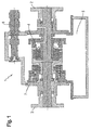
- the embodiment consists of an integrated assembly in which a drive shaft unit 2 is performed via a multi-plate clutch 4 and a holding brake 7 on a driven shaft unit 3. Hydraulic oil is provided from an oil sump 5, which is conveyed for example via a connected pump 6.
- the holding brake 7, like the multi-plate clutch 4, is a dynamically controllable module.
- FIG. 2 For example, the rotational speed of a drive shaft 21 driven by an engine 20 and an output shaft 24 transmitting on a work machine 25 is compared.
- the control unit (not shown) ensures that a corresponding torque is set, which is indicated by 31.
- FIG. 3 shows an example of an application, with a marine diesel 10 gives its power to the drive shaft 11.
- the operating group unit 1 transmits power as needed to the output shaft 13. Via a gear 14, a propeller 15 of a propeller group 12 is driven accordingly.
Landscapes
- Engineering & Computer Science (AREA)
- General Engineering & Computer Science (AREA)
- Mechanical Engineering (AREA)
- Chemical & Material Sciences (AREA)
- Combustion & Propulsion (AREA)
- Ocean & Marine Engineering (AREA)
- Hydraulic Clutches, Magnetic Clutches, Fluid Clutches, And Fluid Joints (AREA)
- Braking Arrangements (AREA)
- Control Of Transmission Device (AREA)
Priority Applications (4)
| Application Number | Priority Date | Filing Date | Title |
|---|---|---|---|
| EP16166127.7A EP3236101B1 (fr) | 2016-04-20 | 2016-04-20 | Accouplement |
| CN201610346518.XA CN105864314B (zh) | 2016-04-20 | 2016-05-23 | 离合器组件 |
| US15/172,521 US10352386B2 (en) | 2016-04-20 | 2016-06-03 | Clutch assembly |
| JP2017074228A JP7144128B2 (ja) | 2016-04-20 | 2017-04-04 | クラッチアセンブリ |
Applications Claiming Priority (1)
| Application Number | Priority Date | Filing Date | Title |
|---|---|---|---|
| EP16166127.7A EP3236101B1 (fr) | 2016-04-20 | 2016-04-20 | Accouplement |
Publications (2)
| Publication Number | Publication Date |
|---|---|
| EP3236101A1 true EP3236101A1 (fr) | 2017-10-25 |
| EP3236101B1 EP3236101B1 (fr) | 2021-03-17 |
Family
ID=55970771
Family Applications (1)
| Application Number | Title | Priority Date | Filing Date |
|---|---|---|---|
| EP16166127.7A Active EP3236101B1 (fr) | 2016-04-20 | 2016-04-20 | Accouplement |
Country Status (4)
| Country | Link |
|---|---|
| US (1) | US10352386B2 (fr) |
| EP (1) | EP3236101B1 (fr) |
| JP (1) | JP7144128B2 (fr) |
| CN (1) | CN105864314B (fr) |
Families Citing this family (2)
| Publication number | Priority date | Publication date | Assignee | Title |
|---|---|---|---|---|
| US20180252272A1 (en) * | 2017-03-06 | 2018-09-06 | Wpt Power Corporation | Power takeoff unit with actuation and lubrication fluid channels |
| EP3592643B1 (fr) | 2017-03-10 | 2023-06-14 | ZF Friedrichshafen AG | Agencement de transmission saildrive |
Citations (5)
| Publication number | Priority date | Publication date | Assignee | Title |
|---|---|---|---|---|
| US5190129A (en) * | 1992-01-24 | 1993-03-02 | Midwest Brake Bond Co. | Press drive with oil shear clutch/brake drives |
| WO1996001957A1 (fr) * | 1994-07-07 | 1996-01-25 | Midwest Brake Bond Company | Commande de presse a embrayage/frein a huile fonctionnant par friction a volant de freinage interne |
| EP2090800A1 (fr) * | 2008-02-15 | 2009-08-19 | Herion Systemtechnik GmbH | Combinaison de freinage pour embrayage |
| EP2295825A2 (fr) * | 2008-07-08 | 2011-03-16 | Goizper, S. Coop. | Dispositif de frein et embrayage combiné pour presses |
| DE102015114926A1 (de) * | 2015-09-07 | 2016-03-03 | Desch Antriebstechnik Gmbh & Co. Kg | Kombinierte Kupplungs- und Bremsvorrichtung, Verwendung einer Kupplungs- und Bremsvorrichtung und Verfahren zur Betätigung einer Kupplungs- und Bremsvorrichtung |
Family Cites Families (20)
| Publication number | Priority date | Publication date | Assignee | Title |
|---|---|---|---|---|
| US2658412A (en) * | 1948-04-13 | 1953-11-10 | Borg Warner | Transmission |
| GB665743A (en) * | 1948-10-29 | 1952-01-30 | Albert Doebeli | Improvements in and relating to electro-magnetically actuated friction couplings with servo-action, more particularly for power driven vehicles |
| US2786560A (en) * | 1953-08-07 | 1957-03-26 | Lambert & Brake Corp | Clutch and brake combination for power transmission systems of farm tractors and thelike |
| US4074581A (en) * | 1976-05-11 | 1978-02-21 | Caterpillar Tractor Co. | Compact transmission having a power takeoff shaft and hydraulically actuated clutches |
| JPS5786643A (en) * | 1980-11-17 | 1982-05-29 | Komatsu Ltd | Clutch brake for vehicle |
| EP0200335B1 (fr) * | 1985-04-03 | 1989-11-15 | Eaton Corporation | Structure d'embrayage pour déconnecter et court-circuiter un convertisseur de couple pour transmission mécanique automatique |
| US4828089A (en) * | 1985-05-07 | 1989-05-09 | Eaton Corporation | Brake/clutch with direct liquid cooling |
| JP2503709B2 (ja) * | 1990-02-26 | 1996-06-05 | 株式会社豊田自動織機製作所 | 産業車両におけるインチング制御装置 |
| JP2590343Y2 (ja) * | 1991-03-06 | 1999-02-10 | 株式会社 神崎高級工機製作所 | 舶用推進装置 |
| JPH06144377A (ja) * | 1991-11-15 | 1994-05-24 | Yanmar Diesel Engine Co Ltd | 減速逆転機の中立ブレーキ解除装置 |
| US5291977A (en) * | 1992-07-27 | 1994-03-08 | Midwest Brake Bond Co. | Electrically actuated clutch brake apparatus |
| JP2004042801A (ja) * | 2002-07-12 | 2004-02-12 | Komatsu Forklift Co Ltd | 産業車両の走行制御装置 |
| CN1884866A (zh) * | 2006-06-30 | 2006-12-27 | 刘建平 | 机动车柔性可控离合装置 |
| JP2009202732A (ja) * | 2008-02-27 | 2009-09-10 | Yamaha Motor Co Ltd | 船舶用推進システム |
| US9194473B1 (en) * | 2009-06-26 | 2015-11-24 | Hydro-Gear Limited Partnership | Modular power distribution and drive system |
| US8393236B1 (en) * | 2009-06-26 | 2013-03-12 | Hydro-Gear Limited Partnership | Modular power distribution and drive system |
| CN201902488U (zh) * | 2010-12-31 | 2011-07-20 | 周云飞 | 一种带离合器的车辆缓速装置 |
| US9221336B1 (en) * | 2011-11-14 | 2015-12-29 | Hydro-Gear Limited Partnership | Integral power distribution assembly for engine |
| JP6110603B2 (ja) * | 2012-04-24 | 2017-04-05 | 富士重工業株式会社 | 車両 |
| PL3416847T3 (pl) * | 2016-02-18 | 2024-01-22 | Twin Disc, Inc. | Hydrauliczna przystawka odbioru mocy z układem rozłączania hamulca do napędów przemysłowych |
-
2016
- 2016-04-20 EP EP16166127.7A patent/EP3236101B1/fr active Active
- 2016-05-23 CN CN201610346518.XA patent/CN105864314B/zh active Active
- 2016-06-03 US US15/172,521 patent/US10352386B2/en active Active
-
2017
- 2017-04-04 JP JP2017074228A patent/JP7144128B2/ja active Active
Patent Citations (5)
| Publication number | Priority date | Publication date | Assignee | Title |
|---|---|---|---|---|
| US5190129A (en) * | 1992-01-24 | 1993-03-02 | Midwest Brake Bond Co. | Press drive with oil shear clutch/brake drives |
| WO1996001957A1 (fr) * | 1994-07-07 | 1996-01-25 | Midwest Brake Bond Company | Commande de presse a embrayage/frein a huile fonctionnant par friction a volant de freinage interne |
| EP2090800A1 (fr) * | 2008-02-15 | 2009-08-19 | Herion Systemtechnik GmbH | Combinaison de freinage pour embrayage |
| EP2295825A2 (fr) * | 2008-07-08 | 2011-03-16 | Goizper, S. Coop. | Dispositif de frein et embrayage combiné pour presses |
| DE102015114926A1 (de) * | 2015-09-07 | 2016-03-03 | Desch Antriebstechnik Gmbh & Co. Kg | Kombinierte Kupplungs- und Bremsvorrichtung, Verwendung einer Kupplungs- und Bremsvorrichtung und Verfahren zur Betätigung einer Kupplungs- und Bremsvorrichtung |
Also Published As
| Publication number | Publication date |
|---|---|
| US20170307037A1 (en) | 2017-10-26 |
| CN105864314B (zh) | 2021-05-04 |
| US10352386B2 (en) | 2019-07-16 |
| EP3236101B1 (fr) | 2021-03-17 |
| CN105864314A (zh) | 2016-08-17 |
| JP7144128B2 (ja) | 2022-09-29 |
| JP2017194155A (ja) | 2017-10-26 |
Similar Documents
| Publication | Publication Date | Title |
|---|---|---|
| DE69528078T2 (de) | Hydraulikmotorsystem | |
| DE69702806T2 (de) | Hybridantrieb mit Zusatzantrieben | |
| EP3468826B1 (fr) | Système hydraulique d'actionnement d'un embrayage muni d'une lubrification à la demande de l'embrayage | |
| EP3080473B1 (fr) | Système hydraulique pour double embrayage ainsi que procédé de commande ou de refroidissement du double embrayage | |
| DE2925268A1 (de) | Vorrichtung zur steuerung eines schwenkrollen-getriebes | |
| EP2503160A1 (fr) | Système d'entraînement hydraulique | |
| EP3954926B1 (fr) | Procédé de réalisation d'une interface de couple et de vitesse de rotation à performances limitées pour transmissions hydrostatiques | |
| DE102011077552A1 (de) | Hydraulikanordnung für ein Getriebe | |
| DE112016001216T5 (de) | Verdrängungspumpenanordnung für antriebsstrangsysteme und hydrauliksteuersystem, das diese einbezieht | |
| DE102017207569B4 (de) | Hydrostatisches Getriebe und Verfahren zur Bremsung damit | |
| DE112009004351B4 (de) | Bremsschmiervorrichtung und Verfahren zu deren Steuerung | |
| DE102018214427A1 (de) | Hydrauliksystem für ein Doppelkupplungsgetriebe | |
| DE102017202273B4 (de) | Hydrostatisches Getriebe und Verfahren zur Bremsung damit | |
| EP3236101B1 (fr) | Accouplement | |
| DE102017103648B4 (de) | Hydraulisches steuersystem | |
| DE102011108946A1 (de) | Verfahren zum Betrieb eines stufenlosen Getriebes mit hydrostatisch-mechanischer Leistungsverzweigung sowie Getriebe zur Durchführung des Verfahrens | |
| DE4019687C2 (de) | Schiffsantrieb mit Trolling-Einrichtung | |
| DE112016001266T5 (de) | Wegeventil für Mehrdruck-Hydrauliksteuersystem | |
| DE102009012805A1 (de) | Vorsatzspindel | |
| DE102014118446B4 (de) | Kreislauf zum Steuern von Hydraulikdruck eines Drehmomentwandlers | |
| DE10358486A1 (de) | Vorrichtung zum Antrieb bewegbarer mechanischer Komponenten | |
| DE10150598A1 (de) | Kupplungssystem mit wenigstens einer druckmittelbetätigbaren, für einen Betrieb unter Einwirkung eines Betriebsmediums vorgesehenen Kupplungsanordnung | |
| EP0470950B1 (fr) | Dispositif d'actionnement electro-hydraulique de l'embrayage de blocage du differentiel repartiteur d'un vehicule | |
| DE102006006179A1 (de) | Vorrichtung zum Betreiben eines hydrodynamischen Drehmomentwandlers und einer damit korrespondierenden Wandlerüberbrückungskupplung einer Getriebeeinrichtung | |
| EP2113688A1 (fr) | Alimentation en fluide de pression pour un agencement d'amortisseur d'oscillations de torsion d'un liquide sous pression |
Legal Events
| Date | Code | Title | Description |
|---|---|---|---|
| PUAI | Public reference made under article 153(3) epc to a published international application that has entered the european phase |
Free format text: ORIGINAL CODE: 0009012 |
|
| STAA | Information on the status of an ep patent application or granted ep patent |
Free format text: STATUS: THE APPLICATION HAS BEEN PUBLISHED |
|
| AK | Designated contracting states |
Kind code of ref document: A1 Designated state(s): AL AT BE BG CH CY CZ DE DK EE ES FI FR GB GR HR HU IE IS IT LI LT LU LV MC MK MT NL NO PL PT RO RS SE SI SK SM TR |
|
| AX | Request for extension of the european patent |
Extension state: BA ME |
|
| STAA | Information on the status of an ep patent application or granted ep patent |
Free format text: STATUS: REQUEST FOR EXAMINATION WAS MADE |
|
| 17P | Request for examination filed |
Effective date: 20180425 |
|
| RBV | Designated contracting states (corrected) |
Designated state(s): AL AT BE BG CH CY CZ DE DK EE ES FI FR GB GR HR HU IE IS IT LI LT LU LV MC MK MT NL NO PL PT RO RS SE SI SK SM TR |
|
| GRAP | Despatch of communication of intention to grant a patent |
Free format text: ORIGINAL CODE: EPIDOSNIGR1 |
|
| STAA | Information on the status of an ep patent application or granted ep patent |
Free format text: STATUS: GRANT OF PATENT IS INTENDED |
|
| INTG | Intention to grant announced |
Effective date: 20201111 |
|
| GRAS | Grant fee paid |
Free format text: ORIGINAL CODE: EPIDOSNIGR3 |
|
| GRAA | (expected) grant |
Free format text: ORIGINAL CODE: 0009210 |
|
| STAA | Information on the status of an ep patent application or granted ep patent |
Free format text: STATUS: THE PATENT HAS BEEN GRANTED |
|
| AK | Designated contracting states |
Kind code of ref document: B1 Designated state(s): AL AT BE BG CH CY CZ DE DK EE ES FI FR GB GR HR HU IE IS IT LI LT LU LV MC MK MT NL NO PL PT RO RS SE SI SK SM TR |
|
| REG | Reference to a national code |
Ref country code: GB Ref legal event code: FG4D Free format text: NOT ENGLISH |
|
| REG | Reference to a national code |
Ref country code: CH Ref legal event code: EP |
|
| REG | Reference to a national code |
Ref country code: DE Ref legal event code: R096 Ref document number: 502016012587 Country of ref document: DE |
|
| REG | Reference to a national code |
Ref country code: IE Ref legal event code: FG4D Free format text: LANGUAGE OF EP DOCUMENT: GERMAN |
|
| REG | Reference to a national code |
Ref country code: AT Ref legal event code: REF Ref document number: 1372522 Country of ref document: AT Kind code of ref document: T Effective date: 20210415 |
|
| REG | Reference to a national code |
Ref country code: LT Ref legal event code: MG9D |
|
| PG25 | Lapsed in a contracting state [announced via postgrant information from national office to epo] |
Ref country code: BG Free format text: LAPSE BECAUSE OF FAILURE TO SUBMIT A TRANSLATION OF THE DESCRIPTION OR TO PAY THE FEE WITHIN THE PRESCRIBED TIME-LIMIT Effective date: 20210617 Ref country code: FI Free format text: LAPSE BECAUSE OF FAILURE TO SUBMIT A TRANSLATION OF THE DESCRIPTION OR TO PAY THE FEE WITHIN THE PRESCRIBED TIME-LIMIT Effective date: 20210317 Ref country code: GR Free format text: LAPSE BECAUSE OF FAILURE TO SUBMIT A TRANSLATION OF THE DESCRIPTION OR TO PAY THE FEE WITHIN THE PRESCRIBED TIME-LIMIT Effective date: 20210618 Ref country code: HR Free format text: LAPSE BECAUSE OF FAILURE TO SUBMIT A TRANSLATION OF THE DESCRIPTION OR TO PAY THE FEE WITHIN THE PRESCRIBED TIME-LIMIT Effective date: 20210317 Ref country code: NO Free format text: LAPSE BECAUSE OF FAILURE TO SUBMIT A TRANSLATION OF THE DESCRIPTION OR TO PAY THE FEE WITHIN THE PRESCRIBED TIME-LIMIT Effective date: 20210617 |
|
| REG | Reference to a national code |
Ref country code: NL Ref legal event code: MP Effective date: 20210317 |
|
| PG25 | Lapsed in a contracting state [announced via postgrant information from national office to epo] |
Ref country code: RS Free format text: LAPSE BECAUSE OF FAILURE TO SUBMIT A TRANSLATION OF THE DESCRIPTION OR TO PAY THE FEE WITHIN THE PRESCRIBED TIME-LIMIT Effective date: 20210317 Ref country code: LV Free format text: LAPSE BECAUSE OF FAILURE TO SUBMIT A TRANSLATION OF THE DESCRIPTION OR TO PAY THE FEE WITHIN THE PRESCRIBED TIME-LIMIT Effective date: 20210317 Ref country code: SE Free format text: LAPSE BECAUSE OF FAILURE TO SUBMIT A TRANSLATION OF THE DESCRIPTION OR TO PAY THE FEE WITHIN THE PRESCRIBED TIME-LIMIT Effective date: 20210317 |
|
| PG25 | Lapsed in a contracting state [announced via postgrant information from national office to epo] |
Ref country code: NL Free format text: LAPSE BECAUSE OF FAILURE TO SUBMIT A TRANSLATION OF THE DESCRIPTION OR TO PAY THE FEE WITHIN THE PRESCRIBED TIME-LIMIT Effective date: 20210317 |
|
| PG25 | Lapsed in a contracting state [announced via postgrant information from national office to epo] |
Ref country code: LT Free format text: LAPSE BECAUSE OF FAILURE TO SUBMIT A TRANSLATION OF THE DESCRIPTION OR TO PAY THE FEE WITHIN THE PRESCRIBED TIME-LIMIT Effective date: 20210317 Ref country code: EE Free format text: LAPSE BECAUSE OF FAILURE TO SUBMIT A TRANSLATION OF THE DESCRIPTION OR TO PAY THE FEE WITHIN THE PRESCRIBED TIME-LIMIT Effective date: 20210317 Ref country code: CZ Free format text: LAPSE BECAUSE OF FAILURE TO SUBMIT A TRANSLATION OF THE DESCRIPTION OR TO PAY THE FEE WITHIN THE PRESCRIBED TIME-LIMIT Effective date: 20210317 Ref country code: SM Free format text: LAPSE BECAUSE OF FAILURE TO SUBMIT A TRANSLATION OF THE DESCRIPTION OR TO PAY THE FEE WITHIN THE PRESCRIBED TIME-LIMIT Effective date: 20210317 |
|
| PG25 | Lapsed in a contracting state [announced via postgrant information from national office to epo] |
Ref country code: IS Free format text: LAPSE BECAUSE OF FAILURE TO SUBMIT A TRANSLATION OF THE DESCRIPTION OR TO PAY THE FEE WITHIN THE PRESCRIBED TIME-LIMIT Effective date: 20210717 Ref country code: PL Free format text: LAPSE BECAUSE OF FAILURE TO SUBMIT A TRANSLATION OF THE DESCRIPTION OR TO PAY THE FEE WITHIN THE PRESCRIBED TIME-LIMIT Effective date: 20210317 Ref country code: PT Free format text: LAPSE BECAUSE OF FAILURE TO SUBMIT A TRANSLATION OF THE DESCRIPTION OR TO PAY THE FEE WITHIN THE PRESCRIBED TIME-LIMIT Effective date: 20210719 Ref country code: SK Free format text: LAPSE BECAUSE OF FAILURE TO SUBMIT A TRANSLATION OF THE DESCRIPTION OR TO PAY THE FEE WITHIN THE PRESCRIBED TIME-LIMIT Effective date: 20210317 Ref country code: RO Free format text: LAPSE BECAUSE OF FAILURE TO SUBMIT A TRANSLATION OF THE DESCRIPTION OR TO PAY THE FEE WITHIN THE PRESCRIBED TIME-LIMIT Effective date: 20210317 |
|
| REG | Reference to a national code |
Ref country code: DE Ref legal event code: R097 Ref document number: 502016012587 Country of ref document: DE |
|
| PG25 | Lapsed in a contracting state [announced via postgrant information from national office to epo] |
Ref country code: LU Free format text: LAPSE BECAUSE OF NON-PAYMENT OF DUE FEES Effective date: 20210420 |
|
| REG | Reference to a national code |
Ref country code: BE Ref legal event code: MM Effective date: 20210430 |
|
| PLBE | No opposition filed within time limit |
Free format text: ORIGINAL CODE: 0009261 |
|
| STAA | Information on the status of an ep patent application or granted ep patent |
Free format text: STATUS: NO OPPOSITION FILED WITHIN TIME LIMIT |
|
| PG25 | Lapsed in a contracting state [announced via postgrant information from national office to epo] |
Ref country code: DK Free format text: LAPSE BECAUSE OF FAILURE TO SUBMIT A TRANSLATION OF THE DESCRIPTION OR TO PAY THE FEE WITHIN THE PRESCRIBED TIME-LIMIT Effective date: 20210317 Ref country code: MC Free format text: LAPSE BECAUSE OF FAILURE TO SUBMIT A TRANSLATION OF THE DESCRIPTION OR TO PAY THE FEE WITHIN THE PRESCRIBED TIME-LIMIT Effective date: 20210317 Ref country code: LI Free format text: LAPSE BECAUSE OF NON-PAYMENT OF DUE FEES Effective date: 20210430 Ref country code: AL Free format text: LAPSE BECAUSE OF FAILURE TO SUBMIT A TRANSLATION OF THE DESCRIPTION OR TO PAY THE FEE WITHIN THE PRESCRIBED TIME-LIMIT Effective date: 20210317 Ref country code: CH Free format text: LAPSE BECAUSE OF NON-PAYMENT OF DUE FEES Effective date: 20210430 Ref country code: ES Free format text: LAPSE BECAUSE OF FAILURE TO SUBMIT A TRANSLATION OF THE DESCRIPTION OR TO PAY THE FEE WITHIN THE PRESCRIBED TIME-LIMIT Effective date: 20210317 |
|
| 26N | No opposition filed |
Effective date: 20211220 |
|
| GBPC | Gb: european patent ceased through non-payment of renewal fee |
Effective date: 20210617 |
|
| PG25 | Lapsed in a contracting state [announced via postgrant information from national office to epo] |
Ref country code: SI Free format text: LAPSE BECAUSE OF FAILURE TO SUBMIT A TRANSLATION OF THE DESCRIPTION OR TO PAY THE FEE WITHIN THE PRESCRIBED TIME-LIMIT Effective date: 20210317 |
|
| PG25 | Lapsed in a contracting state [announced via postgrant information from national office to epo] |
Ref country code: IE Free format text: LAPSE BECAUSE OF NON-PAYMENT OF DUE FEES Effective date: 20210420 Ref country code: GB Free format text: LAPSE BECAUSE OF NON-PAYMENT OF DUE FEES Effective date: 20210617 |
|
| PG25 | Lapsed in a contracting state [announced via postgrant information from national office to epo] |
Ref country code: IS Free format text: LAPSE BECAUSE OF FAILURE TO SUBMIT A TRANSLATION OF THE DESCRIPTION OR TO PAY THE FEE WITHIN THE PRESCRIBED TIME-LIMIT Effective date: 20210717 |
|
| REG | Reference to a national code |
Ref country code: AT Ref legal event code: MM01 Ref document number: 1372522 Country of ref document: AT Kind code of ref document: T Effective date: 20210420 |
|
| PG25 | Lapsed in a contracting state [announced via postgrant information from national office to epo] |
Ref country code: BE Free format text: LAPSE BECAUSE OF NON-PAYMENT OF DUE FEES Effective date: 20210430 |
|
| PG25 | Lapsed in a contracting state [announced via postgrant information from national office to epo] |
Ref country code: AT Free format text: LAPSE BECAUSE OF NON-PAYMENT OF DUE FEES Effective date: 20210420 |
|
| PG25 | Lapsed in a contracting state [announced via postgrant information from national office to epo] |
Ref country code: HU Free format text: LAPSE BECAUSE OF FAILURE TO SUBMIT A TRANSLATION OF THE DESCRIPTION OR TO PAY THE FEE WITHIN THE PRESCRIBED TIME-LIMIT; INVALID AB INITIO Effective date: 20160420 |
|
| P01 | Opt-out of the competence of the unified patent court (upc) registered |
Effective date: 20230522 |
|
| PG25 | Lapsed in a contracting state [announced via postgrant information from national office to epo] |
Ref country code: CY Free format text: LAPSE BECAUSE OF FAILURE TO SUBMIT A TRANSLATION OF THE DESCRIPTION OR TO PAY THE FEE WITHIN THE PRESCRIBED TIME-LIMIT Effective date: 20210317 |
|
| PG25 | Lapsed in a contracting state [announced via postgrant information from national office to epo] |
Ref country code: MK Free format text: LAPSE BECAUSE OF FAILURE TO SUBMIT A TRANSLATION OF THE DESCRIPTION OR TO PAY THE FEE WITHIN THE PRESCRIBED TIME-LIMIT Effective date: 20210317 |
|
| PG25 | Lapsed in a contracting state [announced via postgrant information from national office to epo] |
Ref country code: TR Free format text: LAPSE BECAUSE OF FAILURE TO SUBMIT A TRANSLATION OF THE DESCRIPTION OR TO PAY THE FEE WITHIN THE PRESCRIBED TIME-LIMIT Effective date: 20210317 |
|
| PG25 | Lapsed in a contracting state [announced via postgrant information from national office to epo] |
Ref country code: MT Free format text: LAPSE BECAUSE OF FAILURE TO SUBMIT A TRANSLATION OF THE DESCRIPTION OR TO PAY THE FEE WITHIN THE PRESCRIBED TIME-LIMIT Effective date: 20210317 |
|
| PGFP | Annual fee paid to national office [announced via postgrant information from national office to epo] |
Ref country code: DE Payment date: 20250623 Year of fee payment: 10 |
|
| PGFP | Annual fee paid to national office [announced via postgrant information from national office to epo] |
Ref country code: IT Payment date: 20250424 Year of fee payment: 10 |
|
| PGFP | Annual fee paid to national office [announced via postgrant information from national office to epo] |
Ref country code: FR Payment date: 20250425 Year of fee payment: 10 |