EP3236156B1 - Procédé de fabrication d'un bouclier thermique d'une chambre de combustion - Google Patents
Procédé de fabrication d'un bouclier thermique d'une chambre de combustion Download PDFInfo
- Publication number
- EP3236156B1 EP3236156B1 EP17167410.4A EP17167410A EP3236156B1 EP 3236156 B1 EP3236156 B1 EP 3236156B1 EP 17167410 A EP17167410 A EP 17167410A EP 3236156 B1 EP3236156 B1 EP 3236156B1
- Authority
- EP
- European Patent Office
- Prior art keywords
- combustor
- sheet
- panel
- material forming
- combustor panel
- Prior art date
- Legal status (The legal status is an assumption and is not a legal conclusion. Google has not performed a legal analysis and makes no representation as to the accuracy of the status listed.)
- Active
Links
Images


Classifications
-
- F—MECHANICAL ENGINEERING; LIGHTING; HEATING; WEAPONS; BLASTING
- F23—COMBUSTION APPARATUS; COMBUSTION PROCESSES
- F23R—GENERATING COMBUSTION PRODUCTS OF HIGH PRESSURE OR HIGH VELOCITY, e.g. GAS-TURBINE COMBUSTION CHAMBERS
- F23R3/00—Continuous combustion chambers using liquid or gaseous fuel
- F23R3/002—Wall structures
-
- B—PERFORMING OPERATIONS; TRANSPORTING
- B23—MACHINE TOOLS; METAL-WORKING NOT OTHERWISE PROVIDED FOR
- B23P—METAL-WORKING NOT OTHERWISE PROVIDED FOR; COMBINED OPERATIONS; UNIVERSAL MACHINE TOOLS
- B23P15/00—Making specific metal objects by operations not covered by a single other subclass or a group in this subclass
- B23P15/008—Rocket engine parts, e.g. nozzles, combustion chambers
-
- F—MECHANICAL ENGINEERING; LIGHTING; HEATING; WEAPONS; BLASTING
- F23—COMBUSTION APPARATUS; COMBUSTION PROCESSES
- F23M—CASINGS, LININGS, WALLS OR DOORS SPECIALLY ADAPTED FOR COMBUSTION CHAMBERS, e.g. FIREBRIDGES; DEVICES FOR DEFLECTING AIR, FLAMES OR COMBUSTION PRODUCTS IN COMBUSTION CHAMBERS; SAFETY ARRANGEMENTS SPECIALLY ADAPTED FOR COMBUSTION APPARATUS; DETAILS OF COMBUSTION CHAMBERS, NOT OTHERWISE PROVIDED FOR
- F23M5/00—Casings; Linings; Walls
- F23M5/04—Supports for linings
-
- F—MECHANICAL ENGINEERING; LIGHTING; HEATING; WEAPONS; BLASTING
- F23—COMBUSTION APPARATUS; COMBUSTION PROCESSES
- F23R—GENERATING COMBUSTION PRODUCTS OF HIGH PRESSURE OR HIGH VELOCITY, e.g. GAS-TURBINE COMBUSTION CHAMBERS
- F23R3/00—Continuous combustion chambers using liquid or gaseous fuel
- F23R3/02—Continuous combustion chambers using liquid or gaseous fuel characterised by the air-flow or gas-flow configuration
- F23R3/04—Air inlet arrangements
- F23R3/06—Arrangement of apertures along the flame tube
-
- F—MECHANICAL ENGINEERING; LIGHTING; HEATING; WEAPONS; BLASTING
- F23—COMBUSTION APPARATUS; COMBUSTION PROCESSES
- F23R—GENERATING COMBUSTION PRODUCTS OF HIGH PRESSURE OR HIGH VELOCITY, e.g. GAS-TURBINE COMBUSTION CHAMBERS
- F23R2900/00—Special features of, or arrangements for continuous combustion chambers; Combustion processes therefor
- F23R2900/00018—Manufacturing combustion chamber liners or subparts
-
- F—MECHANICAL ENGINEERING; LIGHTING; HEATING; WEAPONS; BLASTING
- F23—COMBUSTION APPARATUS; COMBUSTION PROCESSES
- F23R—GENERATING COMBUSTION PRODUCTS OF HIGH PRESSURE OR HIGH VELOCITY, e.g. GAS-TURBINE COMBUSTION CHAMBERS
- F23R2900/00—Special features of, or arrangements for continuous combustion chambers; Combustion processes therefor
- F23R2900/03042—Film cooled combustion chamber walls or domes
-
- F—MECHANICAL ENGINEERING; LIGHTING; HEATING; WEAPONS; BLASTING
- F23—COMBUSTION APPARATUS; COMBUSTION PROCESSES
- F23R—GENERATING COMBUSTION PRODUCTS OF HIGH PRESSURE OR HIGH VELOCITY, e.g. GAS-TURBINE COMBUSTION CHAMBERS
- F23R2900/00—Special features of, or arrangements for continuous combustion chambers; Combustion processes therefor
- F23R2900/03045—Convection cooled combustion chamber walls provided with turbolators or means for creating turbulences to increase cooling
-
- Y—GENERAL TAGGING OF NEW TECHNOLOGICAL DEVELOPMENTS; GENERAL TAGGING OF CROSS-SECTIONAL TECHNOLOGIES SPANNING OVER SEVERAL SECTIONS OF THE IPC; TECHNICAL SUBJECTS COVERED BY FORMER USPC CROSS-REFERENCE ART COLLECTIONS [XRACs] AND DIGESTS
- Y02—TECHNOLOGIES OR APPLICATIONS FOR MITIGATION OR ADAPTATION AGAINST CLIMATE CHANGE
- Y02T—CLIMATE CHANGE MITIGATION TECHNOLOGIES RELATED TO TRANSPORTATION
- Y02T50/00—Aeronautics or air transport
- Y02T50/60—Efficient propulsion technologies, e.g. for aircraft
Definitions
- the present disclosure relates to a combustor thermal shield to be used in a gas turbine and its method of fabrication.
- Gas turbine engines such as those that power modern commercial and military aircraft, include a fan section to propel the aircraft, a compressor section to pressurize a supply of air from the fan section, a combustor section to burn a hydrocarbon fuel in the presence of the pressurized air, and a turbine section to extract energy from the resultant combustion gases and generate thrust.
- Combustors used in these engines rely on panels of combustor thermal shields to guide combustion gases into the turbine. These panels can be curved, thin-walled cast sheets, with a "cold” side for maintaining thermal shield integrity and life, and an opposite "hot” side for guiding and containing the combustion gases.
- annular combustor design calls for both inner diameter (“ID”) and outer diameter (“OD”) panels as well as a bulkhead panel at the entrance which may or may not be curved, forming an inner and outer diameter wall, between which the combustion gases travel.
- ID inner diameter
- OD outer diameter
- the resultant assembly typically employs a variety of complex thin-walled castings with a variety of integrally cast attachment and cooling features. Any changes to the design result in costly and time-consuming casting changes.
- EP 2873921 A1 discloses a prior art combustion chamber heat shield.
- WO 2015/069466 A1 and US 5560197A A1 disclose other prior art systems.
- the foregoing method may also include treating the sheet of material forming the combustor panel to be a substrate for the cooling feature.
- the sheet of material may comprise a metal alloy.
- the joining may comprise at least one of brazing, welding, soldering, or interference fitting.
- a hot forming press may curve the combustor panel.
- a cold forming press may curve the combustor panel.
- the curving may be performed after additively manufacturing the cooling feature and after attaching the attachment feature.
- the curving may be performed prior to additively manufacturing the cooling feature and prior to attaching the attachment feature.
- Any of the foregoing methods may also include creating a cooling hole in the sheet of material forming the combustor panel.
- joining the cooling feature onto the sheet of material forming the combustor panel may comprise at least one of brazing, welding, soldering, or interference fitting.
- the sheet of material may comprise a metal alloy.
- joining the screw or bolt to the sheet of material may comprise at least one of brazing, welding, soldering or interference fitting.
- curving the panel may comprise using a hot forming press.
- curving the panel may comprise using a cold forming press.
- the curving may be performed after additively manufacturing the cooling feature and after attaching the attachment feature.
- the curving may be performed prior to joining the cooling feature and prior to attaching the attachment feature to the sheet of material forming the combustor panel.
- any reference to singular includes plural embodiments, and any reference to more than one component or step may include a singular embodiment or step.
- Surface shading lines may be used throughout the figures to denote different parts but not necessarily to denote the same or different materials.
- aft refers to the direction associated with the exhaust (e.g., the back end) of a gas turbine engine.
- forward refers to the direction associated with the intake (e.g., the front end) of a gas turbine engine.
- a first component that is "axially outward" of a second component means that a first component is positioned at a greater distance in the aft or forward direction away from the longitudinal center of the gas turbine along the longitudinal axis of the gas turbine, than the second component.
- a first component that is "axially inward” of a second component means that the first component is positioned closer to the longitudinal center of the gas turbine along the longitudinal axis of the gas turbine, than the second component.
- a first component that is "radially outward" of a second component means that a first component is positioned at a greater distance away from the engine central longitudinal axis, than the second component.
- a first component that is “radially inward” of a second component means that the first component is positioned closer to the engine central longitudinal axis, than the second component.
- a first component that is radially inward of a second component rotates through a circumferentially shorter path than the second component.
- the terminology “radially outward” and “radially inward” may also be used relative to references other than the engine central longitudinal axis. For example, a first component of a combustor that is radially inward or radially outward of a second component of a combustor is positioned relative to the central longitudinal axis of the combustor.
- the combustor section may have an annular wall assembly having inner and outer shells that support respective inner and outer heat shielding liners.
- the liners may be comprised of a plurality of heat shields or panels that together define an annular combustion chamber.
- An annular cooling cavity is defined between the respective shells and liners for supplying cooling air to an opposite hot side of the panels through a plurality of strategically placed effusion holes. Impingement holes are located in the shell for supply cooling air from an outer air plenum and into the cavity.
- the effusion holes are generally orientated to create a protective blanket, or, air film over the hot side of the panels, thereby protecting the panels from the hot combustion gases in the chamber.
- Gas turbine engine 2 may be a two-spool turbofan that generally incorporates a fan section 4, a compressor section 6, a combustor section 8 and a turbine section 10.
- Alternative engines may include, for example, an augmentor section among other systems or features.
- fan section 4 can drive air along a bypass flow-path B while compressor section 6 can drive air along a core flow-path C for compression and communication into combustor section 8 then expansion through turbine section 10.
- turbofan gas turbine engine 2 depicted as a turbofan gas turbine engine 2 herein, it should be understood that the concepts described herein are not limited to use with turbofans as the teachings may be applied to other types of turbine engines including three-spool architectures.
- Gas turbine engine 2 may generally comprise a low speed spool 12 and a high speed spool 14 mounted for rotation about an engine central longitudinal axis X-X' relative to an engine static structure 16 via several bearing systems 18-1, 18-2, and 18-3. It should be understood that various bearing systems at various locations may alternatively or additionally be provided, including for example, bearing system 18-1, bearing system 18-2, and bearing system 18-3.
- Low speed spool 12 may generally comprise an inner shaft 20 that interconnects a fan 22, a low pressure compressor section 24 (e.g., a first compressor section) and a low pressure turbine section 26 (e.g., a first turbine section).
- Inner shaft 20 may be connected to fan 22 through a geared architecture 28 that can drive the fan 22 at a lower speed than low speed spool 12.
- Geared architecture 28 may comprise a gear assembly 42 enclosed within a gear housing 44.
- Gear assembly 42 couples the inner shaft 20 to a rotating fan structure.
- High speed spool 14 may comprise an outer shaft 30 that interconnects a high pressure compressor section 32 (e.g., second compressor section) and high pressure turbine section 34 (e.g., second turbine section).
- a combustor 36 may be located between high pressure compressor section 32 and high pressure turbine section 34.
- a mid-turbine frame 38 of engine static structure 16 may be located generally between high pressure turbine section 34 and low pressure turbine section 26.
- Mid-turbine frame 38 may support one or more bearing systems 18 (such as 18-3) in turbine section 10.
- Inner shaft 20 and outer shaft 30 may be concentric and rotate via bearing systems 18 about the engine central longitudinal axis X-X', which is collinear with their longitudinal axes.
- a "high pressure" compressor or turbine experiences a higher pressure than a corresponding "low pressure” compressor or turbine.
- the core airflow C may be compressed by low pressure compressor section 24 then high pressure compressor section 32, mixed and burned with fuel in combustor 36, then expanded over high pressure turbine section 34 and low pressure turbine section 26.
- Mid-turbine frame 38 includes airfoils 40, which are in the core airflow path. Turbines 26, 34 rotationally drive the respective low speed spool 12 and high speed spool 14 in response to the expansion.
- Gas turbine engine 2 may be, for example, a high-bypass geared aircraft engine.
- the bypass ratio of gas turbine engine 2 may be greater than about six.
- the bypass ratio of gas turbine engine 2 may be greater than ten.
- geared architecture 28 may be an epicyclic gear train, such as a star gear system (sun gear in meshing engagement with a plurality of star gears supported by a carrier and in meshing engagement with a ring gear) or other gear system.
- Geared architecture 28 may have a gear reduction ratio of greater than about 2.3 and low pressure turbine section 26 may have a pressure ratio that is greater than about 5.
- the bypass ratio of gas turbine engine 2 is greater than about ten.
- the diameter of fan 22 may be significantly larger than that of the low pressure compressor section 24, and the low pressure turbine section 26 may have a pressure ratio that is greater than about 5:1.
- Low pressure turbine section 26 pressure ratio may be measured prior to inlet of low pressure turbine section 26 as related to the pressure at the outlet of low pressure turbine section 26 prior to an exhaust nozzle. It should be understood, however, that the above parameters are exemplary of various embodiments of a suitable geared architecture engine and that the present disclosure contemplates other turbine engines including direct drive turbofans.
- next generation of turbofan engines may be designed for higher efficiency, which may be associated with higher pressure ratios and higher temperatures in the high speed spool 14. These higher operating temperatures and pressure ratios may create operating environments that may cause thermal loads that are higher than thermal loads conventionally encountered, which may shorten the operational life of current components.
- operating conditions in high pressure compressor section 32 may be approximately 1400 °F (approximately 760 °C) or more, and operating conditions in combustor 36 may be higher.
- combustor section 8 may comprise one or more combustor 36.
- the core airflow C may be compressed, then mixed with fuel and ignited in the combustor 36 to produce high speed exhaust gases.
- Combustor 36 is thus exposed to high temperature flame and/or gases during the operation of the gas turbine engine 2.
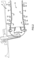
- one or more combustor thermal shields 108 may be positioned in combustor 36 to protect various features of the combustor 36 from the high temperature flame and/or gases.
- a combustor 36 may comprise a combustor chamber 102 defined by a combustor outer shell 104 and a combustor inner shell 184.
- the combustor chamber 102 may form a region of mixing of core airflow C and fuel, and may direct the high-speed exhaust gases produced by the ignition of this mixture inside the combustor 36.
- the combustor outer shell 104 and the combustor inner shell 184 may provide structural support to the combustor 36 and its components.
- a combustor outer shell 104 and a combustor inner shell 184 may comprise a substantially cylindrical canister portion defining an inner area comprising the combustor chamber 102.
- One or more combustor thermal shields 108 may be disposed inside the combustor chamber 102 and may provide such protection.
- a combustor thermal shield 108 may comprise a partial cylindrical surface section (e.g., may have a cross-section comprising an arc length).
- One or more combustor thermal shields 108 may be arranged radially inward of the combustor outer shell 104, for example, circumferentially about the inner surface of the combustor outer shell 104.
- One or more combustor thermal shields 108 may also be arranged radially outward of the combustor inner shell 184.
- the combustor thermal shields 108 may comprise a variety of materials.
- a material deposition process or an “additive material deposition process” may include at least one of 3D printing, lithography such as stereolithography (“SLA”), various laser sintering processes, or any other appropriate technique or combination of techniques.
- a combustor thermal shield 108 may be formed by an additive material deposition process wherein materials, including dissimilar materials, such as metal and ceramic, may be mixed according to various ratios and formed into various aspects of a combustor thermal shield 108.
- materials, including dissimilar materials, such as metal and ceramic may be mixed according to various ratios and formed into various aspects of a combustor thermal shield 108.
- a combustor thermal shield 108 may comprise a unitary body, various elements of the combustor thermal shield 108 may have various different material compositions.
- the combustor thermal shields 108 comprise a combustor panel 110, attachment features 114, and cooling features 116.
- a combustor panel 110 may be made of a thermal insulator material.
- the combustor panel 110 may have a partial cylindrical surface section (e.g., may have a cross-section comprising an arc length).
- the combustor panel 110 may be directly exposed to the heat and/or flame in the combustor chamber 102.
- the combustor panel 110 may be made of any suitable heat tolerant material.
- the combustor panel 110 may be resistant to thermal mechanical fatigue, such that cracking and liberation of portions of the combustor panel 110 into the core airflow C may be ameliorated.
- the combustor thermal shield 108 may be made of a material composition including a metal material, or any suitable heat tolerant material.
- the combustor thermal shield 108 comprises one or more attachment features 114.
- the attachment feature 114 comprises a threaded stud that extends through a corresponding aperture in the combustor outer shell 104 or the combustor inner shell 184, and is retained in position by an attachment nut 106 disposed outward of the combustor outer shell 104 and torqued so that the attachment feature 114 is preloaded with a retaining force and securely affixes the combustor thermal shield 108 in substantially fixed position relative to the combustor outer shell 104 or the combustor inner shell 184.
- the attachment feature 114 may be made of a material composition including a metal material, such as an austenitic nickel-chromium-based alloy or any ductile material sufficiently ductile to withstand the pre-loading exerted by the attachment nut 106.
- a metal material such as an austenitic nickel-chromium-based alloy or any ductile material sufficiently ductile to withstand the pre-loading exerted by the attachment nut 106.
- the combustor thermal shield 108 further comprises one or more cooling features 116.
- the cooling features 116 are pins extending radially outward relative to the combustor panel 110.
- the cooling features 116 may mechanically contact the inner face of the combustor outer shell 104 or the combustor inner shell 184 so that in response to the attachment nut 106 tightening, a shield spacing distance is maintained between the combustor thermal shield 108 and the combustor outer shell 104 or the combustor inner shell 184.
- the combustor thermal shield 108 is made by casting a metal material to form the combustor panel 110 and the attachment features 114 in a single piece.
- the cooling features 116 are also cast as part of the combustor panel 110 along with attachment features 114. While casting the combustor thermal shield 108 may result in achieving a required curved profile in a structurally solid product, if adjustments to the overall design of the arrangement of combustor thermal shields 108 within the combustor 36 are modified, fabricating the adjusted combustor thermal shields 108 by casting may prove to be expensive, both in terms of cost and time. Previously cast combustor thermal shields may not be capable of adjustment, which means adjustments to combustor thermal shield design results in re-casting of the combustor thermal shields 108.
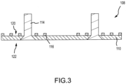
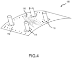
- a flat sheet of prefabricated wrought sheet of material may be used to form the combustor panel 110 (as shown in FIG. 3 ), and later curved (as shown in FIG. 4 ) to achieve a desired profile according to the design of the combustor 36.
- the sheet of material may be a commercially available sheet of metal having properties appropriate for use as a combustor panel, such as being heat tolerant and resistant to heat fatigue.
- the sheet of metal is made of a nickel based superalloy.
- Attachment features 114 are attached by creating or drilling a hole in the sheet of material to create an aperture.
- a screw or bolt forming the attachment feature 114 is inserted into the aperture and the screw or bolt is permanently joined to the sheet of material.
- the screw or bolt is joined by brazing, welding, soldering, or interference fitting.
- the screw or bolt is welded on the side 122 of the combustor panel 110 which will face axially inward when installed in the combustor 36 on the combustor outer shell 104 and axially outward when installed in the combustor 36 on the combustor inner shell 184.
- the attachment point of the sheet of material and the screw or bolt is ground down or sanded down to create a substantially flat surface on the "hot side" facing the combustion gases.
- Cooling features 116 are formed on the sheet of material forming the combustor panel 110 using an additive process, to either a flat sheet or a curved sheet.
- the cooling features 116 are fabricated separately and bonded to the sheet of material, either to a flat sheet or a curved sheet.
- the cooling features 116 may be fabricated onto a flat sheet substrate and subsequently bonded, welded, or brazed onto the flat or curved sheet of material onto side 120, which will face axially outward when the combustor thermal shield 108 is installed in the combustor 36 on the combustor outer shell 104 or will face axially inward when the combustor thermal shield 108 is installed in the combustor 36 on the combustor inner shell 184.
- holes may be created when the panel is in a flat or curved state.
- the holes are cooling holes 118 formed by drilling or creating holes into the sheet of material forming the combustor panel 110.
- the holes may also be diffusion or effusion holes, ignitor holes, fuel nozzle holes, combustion holes, or dilution holes of any size and any arrangement.
- the cooling features 116 are formed separately on a separate sheet of material and the separate sheet of material is bonded to the sheet of material forming the combustor panel 110, either to a flat sheet or a curved sheet.
- the method described herein especially permits test-engine or "rig-based” testing to demonstrate multiple design iterations, such as modifications to cooling features, coating types, or both, within a single test.
- the method described herein also allows scaling of design concepts up or down, to larger or smaller combustors in size, very quickly. Achieving this using casting is impossible, as a cast panel has its shape, curvature, and attachment points fixed.
- a sheet of material is prepared (step 502).
- the sheet of material is a metal material, as described herein.
- the sheet of material is initially formed into rolls, and a section of the roll to be used in the panel is flattened and may be shaped according to the design. Shaping of the sheet of material forming the panel is achieved by milling, grinding, laser cutting, waterjet cutting, or electrical discharge machining. Once flat and shaped, the sheet of material forming the panel may be treated or prepared in order to be a substrate for direct-bonded, additively manufactured cooling features. Treating the sheet of material may include cleaning the sheet of material, priming the sheet of material, chemical etching, or abrasive blasting of the sheet of material. Any combination of the methods of treating the sheet of material may be used.
- Cooling features are added to the sheet of material forming the combustor panel (step 504).
- cooling features include cooling pins (e.g., cooling features 116), cooling holes (e.g., cooling holes 118), fins, rails, and any other feature used for cooling.
- the cooling features are additively manufactured and formed onto the sheet of material forming the combustor panel using additive manufacturing methods.
- the additive manufacturing methods include direct laser metal sintering using powders which may be comprised of the same base alloy as the wrought sheet of metal material.
- the features are welded, soldered, brazed, or interference fit onto the sheet of material forming the panel.
- Attachment features are added to the sheet of material forming the combustor panel (step 506).
- the attachment features may be attached by drilling holes through the panel, inserting an appropriate screw or bolt forming the attachment feature, and joining the screw or bolt to the sheet of material by brazing, welding, soldering, or interference fitting.
- the sheet of material forming the panel is curved according to the design of the combustor (step 508).
- the sheet of material forming the panel is curved using a hot forming press or a cool forming press and the curving is performed in a manner such that loading, load rate, temperatures, and other characteristics of the panel are optimized to retain the additively manufactured features by not allowing for dis-bonding or cracking within the additively manufactured features or between the additively manufactured features and the substrate.
- the process 500 illustrates adding cooling features in step 504, adding attachment features in step 506 and then curving the panel in step 508, the order is not critical, and may be switched.
- the attachment features may be attached, the cooling features additively formed, and the panel may then be curved.
- the panel may first be curved, then the cooling features and attachment features added, in any order.
- one of the attachment features or cooling features are added, the panel is curved, and then the other of the cooling features or attachment features are added.
- Coatings are applied to the combustor panel (step 510).
- the coatings provide structural support and rigidity for the combustor panel.
- the coatings provide thermal resistance and oxidation resistance properties to the combustor panel.
- attachment features and/or cooling features may be added to, removed from, or relocated on the curved combustor panel.
- cooling and attachment features in cast panels are typically easily damaged, particularly the attachment features.
- the time and cost of replacing the damaged features is significantly reduced.
- cooling and attachment features in cast panels are damaged, the entire panel is replaced or performance is affected.
- the screw or bolt forming the damaged attachment feature is first removed. Then, a hole in the combustor panel is created. In various embodiments, removal of the screw or bolt forming the damaged attachment feature creates the hole. A new screw or bolt forming the replacement attachment feature is inserted and the new screw or bolt is attached to the combustor panel, as described herein. Also as described herein, the attachment feature addition process may be performed on an already curved combustor panel, so the sheet of material forming the combustor panel is not required to be flattened prior to replacement of the damaged attachment feature.
- the damaged cooling feature is first removed from the combustor panel.
- the combustor panel is prepared to be a substrate for a new additively manufactured cooling feature.
- the additively manufactured replacement cooling feature is formed on the combustor panel. As described herein, the additive manufacturing process may be performed on a curved combustor panel, so the sheet of material forming the combustor panel is no longer flattened prior to forming of the replacement cooling feature.
Landscapes
- Engineering & Computer Science (AREA)
- Chemical & Material Sciences (AREA)
- Combustion & Propulsion (AREA)
- Mechanical Engineering (AREA)
- General Engineering & Computer Science (AREA)
- Turbine Rotor Nozzle Sealing (AREA)
- Powder Metallurgy (AREA)
Claims (13)
- Procédé de fabrication d'un bouclier thermique de chambre de combustion (108) destiné à être utilisé dans une chambre de combustion de moteur à turbine à gaz (36), le procédé comprenant :la mise en forme d'une feuille de matériau utilisée pour former un panneau de chambre de combustion (110) du bouclier thermique de chambre de combustion (108) par fraisage, meulage, découpe au laser, découpe au jet d'eau ou usinage par décharge électrique ;la fabrication de manière additive d'un élément de refroidissement (116) sur la feuille de matériau formant le panneau de chambre de combustion (110) ;la fixation d'un élément de fixation (114) à la feuille de matériau formant le panneau de chambre de combustion (110) ; etaprès la mise en forme de la feuille de matériau, la courbure de la feuille de matériau formant le panneau de chambre de combustion (110) pour obtenir un profil courbe selon une conception de la chambre de combustion de moteur à turbine à gaz (36), dans lequel la fixation de l'élément de fixation (114) à la feuille du matériau formant le panneau de chambre de combustion (110) comprend :la création d'un trou dans la feuille de matériau formant le panneau de chambre de combustion (110) ;l'insertion d'au moins un parmi un goujon fileté, une vis ou un boulon à travers le trou, l'au moins un parmi le goujon fileté, la vis ou le boulon formant l'élément de fixation (114) ; etl'assemblage de l'au moins un parmi le goujon fileté, la vis ou le boulon à la feuille de matériau formant le panneau de chambre de combustion (110), dans lequel un point de fixation de la feuille de matériau et de l'au moins un goujon fileté, une vis ou un boulon est meulé vers le bas ou poncé pour créer une surface plate sur un côté chaud du panneau de chambre de combustion (110) configuré pour faire face à des gaz de combustion.
- Procédé selon la revendication 1, comprenant en outre le traitement de la feuille de matériau formant le panneau de chambre de combustion (110) pour en faire un substrat pour l'élément de refroidissement (116).
- Procédé selon la revendication 1 ou 2, comprenant en outre la création d'un trou de refroidissement (118) dans la feuille de matériau formant le panneau de chambre de combustion (110).
- Procédé selon la revendication 1, 2 ou 3, dans lequel la courbure est réalisée avant la fabrication additive de l'élément de refroidissement (116) et avant la fixation de l'élément de fixation (114).
- Procédé de fabrication d'un bouclier thermique de chambre de combustion (108) destiné à être utilisé dans une chambre de combustion de moteur à turbine à gaz (36), le procédé comprenant :la mise en forme d'une feuille de matériau utilisée pour former un panneau de chambre de combustion (110) du bouclier thermique de chambre de combustion (108) ;la fabrication de manière additive séparée d'un élément de refroidissement (116) ;l'assemblage de l'élément de refroidissement (116) sur la feuille de matériau formant le panneau de chambre de combustion (110) ;la fixation d'un élément de fixation (114) à la feuille de matériau formant le panneau de chambre de combustion (110) ; etaprès la mise en forme de la feuille de matériau, la courbure de la feuille de matériau formant le panneau de chambre de combustion (110) pour obtenir un profil courbe selon une conception de la chambre de combustion de moteur à turbine à gaz (36) ;dans lequel l'étape de fixation de l'élément de fixation (114) à la feuille de matériau formant le panneau de chambre de combustion (110) comprend :la création d'un trou dans la feuille de matériau formant le panneau de chambre de combustion (110) ;l'insertion d'au moins un parmi un goujon fileté, une vis ou un boulon à travers le trou, l'au moins un parmi le goujon fileté, la vis ou le boulon formant l'élément de fixation (114) ; etl'assemblage de l'au moins un parmi le goujon fileté, la vis ou le boulon à la feuille de matériau formant le panneau de chambre de combustion (110), dans lequel un point de fixation de la feuille de matériau et de l'au moins un goujon fileté, une vis ou un boulon est meulé vers le bas ou poncé pour créer une surface plate sur un côté chaud du panneau de chambre de combustion (110) configuré pour faire face à des gaz de combustion.
- Procédé selon la revendication 5, dans lequel l'assemblage de l'élément de refroidissement (116) sur la feuille de matériau formant le panneau de chambre de combustion (110) comprend au moins l'un parmi le brasage, le soudage, le brasage tendre ou l'ajustement serré.
- Procédé selon la revendication 5 ou 6, dans lequel la courbure est réalisée avant d'assembler l'élément de refroidissement (116) et avant de fixer l'élément de fixation (114) à la feuille de matériau formant le panneau de combustion (110).
- Procédé selon l'une quelconque des revendications 1 à 3 ou 5, dans lequel la courbure est réalisée après fabrication additive de l'élément de refroidissement (116) et après fixation de l'élément de fixation (114).
- Procédé selon une quelconque revendication précédente, dans lequel la feuille de matériau comprend un alliage métallique.
- Procédé selon une quelconque revendication précédente, dans lequel l'assemblage de la vis ou du boulon à la feuille de matériau comprend au moins l'un parmi le brasage, le soudage, le brasage tendre ou l'ajustement serré.
- Procédé selon une quelconque revendication précédente, dans lequel la courbure du panneau (110) comprend l'utilisation d'une presse de formage à chaud.
- Procédé selon l'une quelconque des revendications 1 à 10, dans lequel la courbure du panneau (110) comprend l'utilisation d'une presse de formage à froid.
- Bouclier thermique de chambre de combustion (108) pour une chambre de combustion de moteur à turbine à gaz (36) fabriqué par le procédé selon une quelconque revendication précédente.
Applications Claiming Priority (1)
| Application Number | Priority Date | Filing Date | Title |
|---|---|---|---|
| US15/134,511 US10443846B2 (en) | 2016-04-21 | 2016-04-21 | Combustor thermal shield fabrication method |
Publications (2)
| Publication Number | Publication Date |
|---|---|
| EP3236156A1 EP3236156A1 (fr) | 2017-10-25 |
| EP3236156B1 true EP3236156B1 (fr) | 2023-03-22 |
Family
ID=58606089
Family Applications (1)
| Application Number | Title | Priority Date | Filing Date |
|---|---|---|---|
| EP17167410.4A Active EP3236156B1 (fr) | 2016-04-21 | 2017-04-20 | Procédé de fabrication d'un bouclier thermique d'une chambre de combustion |
Country Status (2)
| Country | Link |
|---|---|
| US (1) | US10443846B2 (fr) |
| EP (1) | EP3236156B1 (fr) |
Families Citing this family (4)
| Publication number | Priority date | Publication date | Assignee | Title |
|---|---|---|---|---|
| US11377976B2 (en) | 2018-12-19 | 2022-07-05 | Unison Industries, Llc | Surface cooler and method of forming |
| WO2020136565A2 (fr) * | 2018-12-26 | 2020-07-02 | 3M Innovative Properties Company | Brûleurs et procédés de fabrication additive |
| US20200300469A1 (en) | 2019-03-19 | 2020-09-24 | United Technologies Corporation | Aerodynamic component for a gas turbine engine |
| CN113787306B (zh) * | 2021-09-02 | 2023-01-06 | 北京航空航天大学江西研究院 | 一种燃烧室帽罩流动控制精准热成形方法 |
Citations (3)
| Publication number | Priority date | Publication date | Assignee | Title |
|---|---|---|---|---|
| US5560197A (en) * | 1993-12-22 | 1996-10-01 | Societe Nationale D'etude Et De Construction De Moteurs D'aviation "Snecma" | Fixing arrangement for a thermal protection tile in a combustion chamber |
| US20150204543A1 (en) * | 2014-01-17 | 2015-07-23 | Mitsubishi Heavy Industries, Ltd. | Gas turbine combustor and gas turbine |
| CA2903808A1 (fr) * | 2014-10-17 | 2016-04-17 | Pratt & Whitney Canada Corp. | Production de composantes de turbine dotees de caracteristiques d'extraction de chaleur au moyen d'un procede de fabrication additif |
Family Cites Families (17)
| Publication number | Priority date | Publication date | Assignee | Title |
|---|---|---|---|---|
| US4302941A (en) * | 1980-04-02 | 1981-12-01 | United Technologies Corporation | Combuster liner construction for gas turbine engine |
| US4628694A (en) * | 1983-12-19 | 1986-12-16 | General Electric Company | Fabricated liner article and method |
| US4944151A (en) * | 1988-09-26 | 1990-07-31 | Avco Corporation | Segmented combustor panel |
| US5964091A (en) * | 1995-07-11 | 1999-10-12 | Hitachi, Ltd. | Gas turbine combustor and gas turbine |
| US9511447B2 (en) * | 2013-12-12 | 2016-12-06 | General Electric Company | Process for making a turbulator by additive manufacturing |
| US8580672B2 (en) | 2011-10-25 | 2013-11-12 | Globalfoundries Inc. | Methods of forming bump structures that include a protection layer |
| JP5821550B2 (ja) * | 2011-11-10 | 2015-11-24 | 株式会社Ihi | 燃焼器ライナ |
| US8910378B2 (en) * | 2012-05-01 | 2014-12-16 | United Technologies Corporation | Method for working of combustor float wall panels |
| US20140216042A1 (en) * | 2012-09-28 | 2014-08-07 | United Technologies Corporation | Combustor component with cooling holes formed by additive manufacturing |
| DE102012022199A1 (de) * | 2012-11-13 | 2014-05-28 | Rolls-Royce Deutschland Ltd & Co Kg | Brennkammerschindel einer Gasturbine |
| WO2014200588A2 (fr) * | 2013-03-14 | 2014-12-18 | United Technologies Corporation | Panneau d'habillage pour chambre de combustion de moteur à turbine à gaz à fabrication additive |
| US12529321B2 (en) * | 2013-10-02 | 2026-01-20 | Rtx Corporation | Segmented ceramic coating interlayer |
| WO2015057304A1 (fr) | 2013-10-18 | 2015-04-23 | Burd Steven W | Panneaux à trous de refroidissement et ses procédés de fabrication |
| EP3066391B1 (fr) | 2013-11-05 | 2019-01-16 | United Technologies Corporation | Panneau de paroi flottante de chambre de combustion refroidie |
| DE102013223258A1 (de) * | 2013-11-14 | 2015-06-03 | Rolls-Royce Deutschland Ltd & Co Kg | Brennkammerhitzeabschirmelement einer Gasturbine |
| US9517507B2 (en) * | 2014-07-17 | 2016-12-13 | Pratt & Whitney Canada Corp. | Method of shaping green part and manufacturing method using same |
| US10450874B2 (en) * | 2016-02-13 | 2019-10-22 | General Electric Company | Airfoil for a gas turbine engine |
-
2016
- 2016-04-21 US US15/134,511 patent/US10443846B2/en active Active
-
2017
- 2017-04-20 EP EP17167410.4A patent/EP3236156B1/fr active Active
Patent Citations (3)
| Publication number | Priority date | Publication date | Assignee | Title |
|---|---|---|---|---|
| US5560197A (en) * | 1993-12-22 | 1996-10-01 | Societe Nationale D'etude Et De Construction De Moteurs D'aviation "Snecma" | Fixing arrangement for a thermal protection tile in a combustion chamber |
| US20150204543A1 (en) * | 2014-01-17 | 2015-07-23 | Mitsubishi Heavy Industries, Ltd. | Gas turbine combustor and gas turbine |
| CA2903808A1 (fr) * | 2014-10-17 | 2016-04-17 | Pratt & Whitney Canada Corp. | Production de composantes de turbine dotees de caracteristiques d'extraction de chaleur au moyen d'un procede de fabrication additif |
Also Published As
| Publication number | Publication date |
|---|---|
| US10443846B2 (en) | 2019-10-15 |
| EP3236156A1 (fr) | 2017-10-25 |
| US20170307216A1 (en) | 2017-10-26 |
Similar Documents
| Publication | Publication Date | Title |
|---|---|---|
| EP3385621B1 (fr) | Refroidissement d'un bouclier thermique | |
| EP3453965B1 (fr) | Configuration de refroidissement pour caractéristique de fixation de chambre de combustion | |
| EP3587928B1 (fr) | Coque de chambre de combustion | |
| EP3404330B1 (fr) | Rail d'extrémité redondant pour panneau de chambre de combustion | |
| EP3086041B1 (fr) | Écran thermique de brûleur à fabrication additive | |
| EP3032175B1 (fr) | Ensemble paroi refroidi destiné à une chambre de combustion et procédé de conception | |
| EP3453968B1 (fr) | Configurations de refroidissement pour caractéristiques de fixation de chambre de combustion | |
| EP2995863B1 (fr) | Brûleur à paroi unique pour un moteur à turbine à gaz et procédé de fabrication | |
| EP2995864B1 (fr) | Circuit de refroidissement par film pour une chemise de chambre de combustion et procede de fabrication du circuit de refroidissement | |
| EP3236156B1 (fr) | Procédé de fabrication d'un bouclier thermique d'une chambre de combustion | |
| EP3633268B1 (fr) | Enveloppe de chambre de combustion fabriquée de manière additive avec structure de support en matériau consommable | |
| EP3453967B1 (fr) | Panneau de chambre de combustion avec configuration de refroidissement pour élément de fixation dudit panneau | |
| EP3056817B1 (fr) | Écran thermique de chambre de combustion à fabrication additive et méthode de fabrication correspondante | |
| EP3330612A1 (fr) | Systèmes et procédés pour chambre de combustion | |
| EP3453966B1 (fr) | Panneau de chambre de combustion | |
| EP3453969B1 (fr) | Panneaux de chambre de combustion avec des caractéristiques de fixation | |
| US11175041B2 (en) | Systems and methods for combustor panel |
Legal Events
| Date | Code | Title | Description |
|---|---|---|---|
| PUAI | Public reference made under article 153(3) epc to a published international application that has entered the european phase |
Free format text: ORIGINAL CODE: 0009012 |
|
| STAA | Information on the status of an ep patent application or granted ep patent |
Free format text: STATUS: THE APPLICATION HAS BEEN PUBLISHED |
|
| AK | Designated contracting states |
Kind code of ref document: A1 Designated state(s): AL AT BE BG CH CY CZ DE DK EE ES FI FR GB GR HR HU IE IS IT LI LT LU LV MC MK MT NL NO PL PT RO RS SE SI SK SM TR |
|
| AX | Request for extension of the european patent |
Extension state: BA ME |
|
| STAA | Information on the status of an ep patent application or granted ep patent |
Free format text: STATUS: REQUEST FOR EXAMINATION WAS MADE |
|
| 17P | Request for examination filed |
Effective date: 20180425 |
|
| RBV | Designated contracting states (corrected) |
Designated state(s): AL AT BE BG CH CY CZ DE DK EE ES FI FR GB GR HR HU IE IS IT LI LT LU LV MC MK MT NL NO PL PT RO RS SE SI SK SM TR |
|
| STAA | Information on the status of an ep patent application or granted ep patent |
Free format text: STATUS: EXAMINATION IS IN PROGRESS |
|
| 17Q | First examination report despatched |
Effective date: 20200127 |
|
| RAP1 | Party data changed (applicant data changed or rights of an application transferred) |
Owner name: RAYTHEON TECHNOLOGIES CORPORATION |
|
| GRAJ | Information related to disapproval of communication of intention to grant by the applicant or resumption of examination proceedings by the epo deleted |
Free format text: ORIGINAL CODE: EPIDOSDIGR1 |
|
| GRAP | Despatch of communication of intention to grant a patent |
Free format text: ORIGINAL CODE: EPIDOSNIGR1 |
|
| GRAP | Despatch of communication of intention to grant a patent |
Free format text: ORIGINAL CODE: EPIDOSNIGR1 |
|
| STAA | Information on the status of an ep patent application or granted ep patent |
Free format text: STATUS: GRANT OF PATENT IS INTENDED |
|
| INTG | Intention to grant announced |
Effective date: 20220419 |
|
| GRAJ | Information related to disapproval of communication of intention to grant by the applicant or resumption of examination proceedings by the epo deleted |
Free format text: ORIGINAL CODE: EPIDOSDIGR1 |
|
| STAA | Information on the status of an ep patent application or granted ep patent |
Free format text: STATUS: EXAMINATION IS IN PROGRESS |
|
| GRAP | Despatch of communication of intention to grant a patent |
Free format text: ORIGINAL CODE: EPIDOSNIGR1 |
|
| STAA | Information on the status of an ep patent application or granted ep patent |
Free format text: STATUS: GRANT OF PATENT IS INTENDED |
|
| INTC | Intention to grant announced (deleted) | ||
| INTG | Intention to grant announced |
Effective date: 20221005 |
|
| GRAS | Grant fee paid |
Free format text: ORIGINAL CODE: EPIDOSNIGR3 |
|
| GRAA | (expected) grant |
Free format text: ORIGINAL CODE: 0009210 |
|
| STAA | Information on the status of an ep patent application or granted ep patent |
Free format text: STATUS: THE PATENT HAS BEEN GRANTED |
|
| AK | Designated contracting states |
Kind code of ref document: B1 Designated state(s): AL AT BE BG CH CY CZ DE DK EE ES FI FR GB GR HR HU IE IS IT LI LT LU LV MC MK MT NL NO PL PT RO RS SE SI SK SM TR |
|
| REG | Reference to a national code |
Ref country code: GB Ref legal event code: FG4D |
|
| REG | Reference to a national code |
Ref country code: CH Ref legal event code: EP |
|
| REG | Reference to a national code |
Ref country code: IE Ref legal event code: FG4D |
|
| REG | Reference to a national code |
Ref country code: DE Ref legal event code: R096 Ref document number: 602017066960 Country of ref document: DE |
|
| REG | Reference to a national code |
Ref country code: AT Ref legal event code: REF Ref document number: 1555508 Country of ref document: AT Kind code of ref document: T Effective date: 20230415 |
|
| P01 | Opt-out of the competence of the unified patent court (upc) registered |
Effective date: 20230520 |
|
| REG | Reference to a national code |
Ref country code: LT Ref legal event code: MG9D |
|
| REG | Reference to a national code |
Ref country code: NL Ref legal event code: MP Effective date: 20230322 |
|
| PG25 | Lapsed in a contracting state [announced via postgrant information from national office to epo] |
Ref country code: RS Free format text: LAPSE BECAUSE OF FAILURE TO SUBMIT A TRANSLATION OF THE DESCRIPTION OR TO PAY THE FEE WITHIN THE PRESCRIBED TIME-LIMIT Effective date: 20230322 Ref country code: NO Free format text: LAPSE BECAUSE OF FAILURE TO SUBMIT A TRANSLATION OF THE DESCRIPTION OR TO PAY THE FEE WITHIN THE PRESCRIBED TIME-LIMIT Effective date: 20230622 Ref country code: LV Free format text: LAPSE BECAUSE OF FAILURE TO SUBMIT A TRANSLATION OF THE DESCRIPTION OR TO PAY THE FEE WITHIN THE PRESCRIBED TIME-LIMIT Effective date: 20230322 Ref country code: LT Free format text: LAPSE BECAUSE OF FAILURE TO SUBMIT A TRANSLATION OF THE DESCRIPTION OR TO PAY THE FEE WITHIN THE PRESCRIBED TIME-LIMIT Effective date: 20230322 Ref country code: HR Free format text: LAPSE BECAUSE OF FAILURE TO SUBMIT A TRANSLATION OF THE DESCRIPTION OR TO PAY THE FEE WITHIN THE PRESCRIBED TIME-LIMIT Effective date: 20230322 |
|
| REG | Reference to a national code |
Ref country code: AT Ref legal event code: MK05 Ref document number: 1555508 Country of ref document: AT Kind code of ref document: T Effective date: 20230322 |
|
| PG25 | Lapsed in a contracting state [announced via postgrant information from national office to epo] |
Ref country code: SE Free format text: LAPSE BECAUSE OF FAILURE TO SUBMIT A TRANSLATION OF THE DESCRIPTION OR TO PAY THE FEE WITHIN THE PRESCRIBED TIME-LIMIT Effective date: 20230322 Ref country code: NL Free format text: LAPSE BECAUSE OF FAILURE TO SUBMIT A TRANSLATION OF THE DESCRIPTION OR TO PAY THE FEE WITHIN THE PRESCRIBED TIME-LIMIT Effective date: 20230322 Ref country code: GR Free format text: LAPSE BECAUSE OF FAILURE TO SUBMIT A TRANSLATION OF THE DESCRIPTION OR TO PAY THE FEE WITHIN THE PRESCRIBED TIME-LIMIT Effective date: 20230623 Ref country code: FI Free format text: LAPSE BECAUSE OF FAILURE TO SUBMIT A TRANSLATION OF THE DESCRIPTION OR TO PAY THE FEE WITHIN THE PRESCRIBED TIME-LIMIT Effective date: 20230322 |
|
| PG25 | Lapsed in a contracting state [announced via postgrant information from national office to epo] |
Ref country code: SM Free format text: LAPSE BECAUSE OF FAILURE TO SUBMIT A TRANSLATION OF THE DESCRIPTION OR TO PAY THE FEE WITHIN THE PRESCRIBED TIME-LIMIT Effective date: 20230322 Ref country code: RO Free format text: LAPSE BECAUSE OF FAILURE TO SUBMIT A TRANSLATION OF THE DESCRIPTION OR TO PAY THE FEE WITHIN THE PRESCRIBED TIME-LIMIT Effective date: 20230322 Ref country code: PT Free format text: LAPSE BECAUSE OF FAILURE TO SUBMIT A TRANSLATION OF THE DESCRIPTION OR TO PAY THE FEE WITHIN THE PRESCRIBED TIME-LIMIT Effective date: 20230724 Ref country code: ES Free format text: LAPSE BECAUSE OF FAILURE TO SUBMIT A TRANSLATION OF THE DESCRIPTION OR TO PAY THE FEE WITHIN THE PRESCRIBED TIME-LIMIT Effective date: 20230322 Ref country code: EE Free format text: LAPSE BECAUSE OF FAILURE TO SUBMIT A TRANSLATION OF THE DESCRIPTION OR TO PAY THE FEE WITHIN THE PRESCRIBED TIME-LIMIT Effective date: 20230322 Ref country code: AT Free format text: LAPSE BECAUSE OF FAILURE TO SUBMIT A TRANSLATION OF THE DESCRIPTION OR TO PAY THE FEE WITHIN THE PRESCRIBED TIME-LIMIT Effective date: 20230322 |
|
| RAP4 | Party data changed (patent owner data changed or rights of a patent transferred) |
Owner name: RTX CORPORATION |
|
| PG25 | Lapsed in a contracting state [announced via postgrant information from national office to epo] |
Ref country code: SK Free format text: LAPSE BECAUSE OF FAILURE TO SUBMIT A TRANSLATION OF THE DESCRIPTION OR TO PAY THE FEE WITHIN THE PRESCRIBED TIME-LIMIT Effective date: 20230322 Ref country code: PL Free format text: LAPSE BECAUSE OF FAILURE TO SUBMIT A TRANSLATION OF THE DESCRIPTION OR TO PAY THE FEE WITHIN THE PRESCRIBED TIME-LIMIT Effective date: 20230322 Ref country code: IS Free format text: LAPSE BECAUSE OF FAILURE TO SUBMIT A TRANSLATION OF THE DESCRIPTION OR TO PAY THE FEE WITHIN THE PRESCRIBED TIME-LIMIT Effective date: 20230722 |
|
| REG | Reference to a national code |
Ref country code: CH Ref legal event code: PL |
|
| PG25 | Lapsed in a contracting state [announced via postgrant information from national office to epo] |
Ref country code: LU Free format text: LAPSE BECAUSE OF NON-PAYMENT OF DUE FEES Effective date: 20230420 |
|
| REG | Reference to a national code |
Ref country code: DE Ref legal event code: R097 Ref document number: 602017066960 Country of ref document: DE |
|
| REG | Reference to a national code |
Ref country code: BE Ref legal event code: MM Effective date: 20230430 |
|
| PG25 | Lapsed in a contracting state [announced via postgrant information from national office to epo] |
Ref country code: MC Free format text: LAPSE BECAUSE OF FAILURE TO SUBMIT A TRANSLATION OF THE DESCRIPTION OR TO PAY THE FEE WITHIN THE PRESCRIBED TIME-LIMIT Effective date: 20230322 |
|
| PLBE | No opposition filed within time limit |
Free format text: ORIGINAL CODE: 0009261 |
|
| STAA | Information on the status of an ep patent application or granted ep patent |
Free format text: STATUS: NO OPPOSITION FILED WITHIN TIME LIMIT |
|
| PG25 | Lapsed in a contracting state [announced via postgrant information from national office to epo] |
Ref country code: SI Free format text: LAPSE BECAUSE OF FAILURE TO SUBMIT A TRANSLATION OF THE DESCRIPTION OR TO PAY THE FEE WITHIN THE PRESCRIBED TIME-LIMIT Effective date: 20230322 Ref country code: MC Free format text: LAPSE BECAUSE OF FAILURE TO SUBMIT A TRANSLATION OF THE DESCRIPTION OR TO PAY THE FEE WITHIN THE PRESCRIBED TIME-LIMIT Effective date: 20230322 Ref country code: LI Free format text: LAPSE BECAUSE OF NON-PAYMENT OF DUE FEES Effective date: 20230430 Ref country code: DK Free format text: LAPSE BECAUSE OF FAILURE TO SUBMIT A TRANSLATION OF THE DESCRIPTION OR TO PAY THE FEE WITHIN THE PRESCRIBED TIME-LIMIT Effective date: 20230322 Ref country code: CZ Free format text: LAPSE BECAUSE OF FAILURE TO SUBMIT A TRANSLATION OF THE DESCRIPTION OR TO PAY THE FEE WITHIN THE PRESCRIBED TIME-LIMIT Effective date: 20230322 Ref country code: CH Free format text: LAPSE BECAUSE OF NON-PAYMENT OF DUE FEES Effective date: 20230430 |
|
| REG | Reference to a national code |
Ref country code: IE Ref legal event code: MM4A |
|
| 26N | No opposition filed |
Effective date: 20240102 |
|
| PG25 | Lapsed in a contracting state [announced via postgrant information from national office to epo] |
Ref country code: BE Free format text: LAPSE BECAUSE OF NON-PAYMENT OF DUE FEES Effective date: 20230430 |
|
| PG25 | Lapsed in a contracting state [announced via postgrant information from national office to epo] |
Ref country code: IE Free format text: LAPSE BECAUSE OF NON-PAYMENT OF DUE FEES Effective date: 20230420 |
|
| PG25 | Lapsed in a contracting state [announced via postgrant information from national office to epo] |
Ref country code: IE Free format text: LAPSE BECAUSE OF NON-PAYMENT OF DUE FEES Effective date: 20230420 |
|
| PG25 | Lapsed in a contracting state [announced via postgrant information from national office to epo] |
Ref country code: IT Free format text: LAPSE BECAUSE OF FAILURE TO SUBMIT A TRANSLATION OF THE DESCRIPTION OR TO PAY THE FEE WITHIN THE PRESCRIBED TIME-LIMIT Effective date: 20230322 |
|
| PG25 | Lapsed in a contracting state [announced via postgrant information from national office to epo] |
Ref country code: BG Free format text: LAPSE BECAUSE OF FAILURE TO SUBMIT A TRANSLATION OF THE DESCRIPTION OR TO PAY THE FEE WITHIN THE PRESCRIBED TIME-LIMIT Effective date: 20230322 |
|
| PG25 | Lapsed in a contracting state [announced via postgrant information from national office to epo] |
Ref country code: BG Free format text: LAPSE BECAUSE OF FAILURE TO SUBMIT A TRANSLATION OF THE DESCRIPTION OR TO PAY THE FEE WITHIN THE PRESCRIBED TIME-LIMIT Effective date: 20230322 |
|
| PGFP | Annual fee paid to national office [announced via postgrant information from national office to epo] |
Ref country code: DE Payment date: 20250319 Year of fee payment: 9 |
|
| PG25 | Lapsed in a contracting state [announced via postgrant information from national office to epo] |
Ref country code: CY Free format text: LAPSE BECAUSE OF FAILURE TO SUBMIT A TRANSLATION OF THE DESCRIPTION OR TO PAY THE FEE WITHIN THE PRESCRIBED TIME-LIMIT; INVALID AB INITIO Effective date: 20170420 |
|
| PG25 | Lapsed in a contracting state [announced via postgrant information from national office to epo] |
Ref country code: HU Free format text: LAPSE BECAUSE OF FAILURE TO SUBMIT A TRANSLATION OF THE DESCRIPTION OR TO PAY THE FEE WITHIN THE PRESCRIBED TIME-LIMIT; INVALID AB INITIO Effective date: 20170420 |
|
| REG | Reference to a national code |
Ref country code: DE Ref legal event code: R081 Ref document number: 602017066960 Country of ref document: DE Owner name: RTX CORPORATION (N.D.GES.D. STAATES DELAWARE),, US Free format text: FORMER OWNER: RAYTHEON TECHNOLOGIES CORP., FARMINGTON, CT, US |
|
| PG25 | Lapsed in a contracting state [announced via postgrant information from national office to epo] |
Ref country code: TR Free format text: LAPSE BECAUSE OF FAILURE TO SUBMIT A TRANSLATION OF THE DESCRIPTION OR TO PAY THE FEE WITHIN THE PRESCRIBED TIME-LIMIT Effective date: 20230322 |
|
| PGFP | Annual fee paid to national office [announced via postgrant information from national office to epo] |
Ref country code: GB Payment date: 20260319 Year of fee payment: 10 |
|
| PGFP | Annual fee paid to national office [announced via postgrant information from national office to epo] |
Ref country code: FR Payment date: 20260320 Year of fee payment: 10 |