EP3236806B1 - Procédé de fabrication d'une brosse ou d'un pinceau ainsi que dispositif à cette fin - Google Patents
Procédé de fabrication d'une brosse ou d'un pinceau ainsi que dispositif à cette fin Download PDFInfo
- Publication number
- EP3236806B1 EP3236806B1 EP15808611.6A EP15808611A EP3236806B1 EP 3236806 B1 EP3236806 B1 EP 3236806B1 EP 15808611 A EP15808611 A EP 15808611A EP 3236806 B1 EP3236806 B1 EP 3236806B1
- Authority
- EP
- European Patent Office
- Prior art keywords
- bundle
- bristle
- brush
- strand
- holding portion
- Prior art date
- Legal status (The legal status is an assumption and is not a legal conclusion. Google has not performed a legal analysis and makes no representation as to the accuracy of the status listed.)
- Active
Links
Images



Classifications
-
- A—HUMAN NECESSITIES
- A46—BRUSHWARE
- A46B—BRUSHES
- A46B9/00—Arrangements of the bristles in the brush body
- A46B9/02—Position or arrangement of bristles in relation to surface of the brush body, e.g. inclined, in rows, in groups
- A46B9/021—Position or arrangement of bristles in relation to surface of the brush body, e.g. inclined, in rows, in groups arranged like in cosmetics brushes, e.g. mascara, nail polish, eye shadow
-
- A—HUMAN NECESSITIES
- A46—BRUSHWARE
- A46B—BRUSHES
- A46B9/00—Arrangements of the bristles in the brush body
- A46B9/02—Position or arrangement of bristles in relation to surface of the brush body, e.g. inclined, in rows, in groups
- A46B9/028—Bristle profile, the end of the bristle defining a surface other than a single plane or deviating from a simple geometric form, e.g. cylinder, sphere or cone
-
- A—HUMAN NECESSITIES
- A46—BRUSHWARE
- A46D—MANUFACTURE OF BRUSHES
- A46D1/00—Bristles; Selection of materials for bristles
- A46D1/08—Preparing uniform tufts of bristles
-
- A—HUMAN NECESSITIES
- A46—BRUSHWARE
- A46D—MANUFACTURE OF BRUSHES
- A46D3/00—Preparing, i.e. Manufacturing brush bodies
- A46D3/005—Preparing, i.e. Manufacturing brush bodies by moulding or casting a body around bristles or tufts of bristles
-
- A—HUMAN NECESSITIES
- A46—BRUSHWARE
- A46D—MANUFACTURE OF BRUSHES
- A46D3/00—Preparing, i.e. Manufacturing brush bodies
- A46D3/04—Machines for inserting or fixing bristles in bodies
- A46D3/045—Machines for inserting or fixing bristles in bodies for fixing bristles by fusing or gluing to a body
-
- A—HUMAN NECESSITIES
- A46—BRUSHWARE
- A46B—BRUSHES
- A46B2200/00—Brushes characterized by their functions, uses or applications
- A46B2200/10—For human or animal care
- A46B2200/1046—Brush used for applying cosmetics
-
- A—HUMAN NECESSITIES
- A46—BRUSHWARE
- A46B—BRUSHES
- A46B2200/00—Brushes characterized by their functions, uses or applications
- A46B2200/10—For human or animal care
- A46B2200/1066—Toothbrush for cleaning the teeth or dentures
Definitions
- the invention relates to a method for producing a brush or a paintbrush, in particular a paintbrush such as a nail polish brush, by fastening at least one bundle of bristles to a support section of the brush or the paintbrush without anchoring.
- the invention also relates to a device for producing a brush or a paintbrush, by means of which at least one bundle of bristles is fastened to the brush or the paintbrush without anchoring.
- Anchors are either metal plates or wire loops that lock folded bundles of bristles to a holding section of the brush or paintbrush and cut into the edge of the corresponding opening.
- the holding section of the brush is the part of the brush body to which at least one bundle of bristles is attached.
- the holding section is an integral part of the brush body.
- Another variant provides for the brush body to be made of several parts, so that a type of plate or tube is first produced, to which or in which the bundle of bristles is then attached. This separate part is then connected to the rest of the brush body.
- the rest of the brush body can already be manufactured and form a separate part, which is then connected to the bristled part, for example by gluing.
- the bristled part can also be overmolded, whereby the rest of the brush body is then manufactured.
- the bristle bundle is attached by the openings in the corresponding part with the holding section.
- the bristle ends are connected to one another at the back, for example by thermal forming, ie melting.
- This section of the brush is then covered at the back by means of a cover or by means of an overmoulding.
- Another possibility for fastening without an anchor is to arrange the bristle bundle(s) in an injection moulding tool insert and, after the bristles have been connected at the back, to overmould the bundle(s) at their rear end.
- the bristle bundles are taken from a magazine in which the bristles are arranged next to each other and are stored under lateral pre-tension.
- a so-called bundle remover takes an individual bundle from this magazine.
- a brush manufacturing machine which has a multiple feed for strand-shaped bristle material with a feed device for the bristle strands. Furthermore, a cutting device for bristle bundles and a feed device for feeding the bristle bundles to a device for connecting the bristle bundles to a brush body are provided. Shearing devices for cutting the bristle strands are arranged next to them. The bristle strands are introduced into a bundle carrier and then cut off so that bristle bundles are formed in the bundle carrier. The bristle bundles are then pushed into a perforated plate by a pusher.
- the EN 10 2009 053 663 A1 discloses a method for the anchorless production of bristle goods.
- Strand-shaped bristle material is introduced into a bundle carrier and a bristle bundle is then formed by cutting the strand-shaped bristle material with a knife.
- the bristle bundle is then transported into the bristle body using compressed air.
- the brush body acts as a holding section for the bristle bundle.
- the present invention provides a method for producing a brush and an apparatus for producing a brush in which the bristle supply is simplified.
- the bundle carrier is already the holding section of the brush or paintbrush itself.
- the holding section is therefore part of the later brush or paintbrush body.
- the holding section itself can merge into the rest of the brush or paintbrush body as one piece and form a section of it. This is the case, for example, when the entire brush body of a toothbrush, including the head, neck and handle, is manufactured in advance and then stuffed and possibly only overmolded on the back in the head area.
- the holding section can be a previously manufactured component, for example a plate with one or more openings or a sleeve on a paintbrush. This stuffed component is then part of the later brush or paintbrush body by being subsequently connected to the rest of the brush or paintbrush body, for example by overmolded or by attaching it to another prefabricated part of the body, e.g. the handle.
- the already cut bristles are not taken from a magazine, but immediately before the production of the brush or paintbrush, they are taken from at least one endless spool and only cut off in the bundle carrier. This means that this cutting of the bristles takes place in the device for producing the brush itself.
- the fibers are of course preferably arranged parallel in the spool and not twisted together as in a rope.
- strands can be pulled off several spools at the same time and combined into a common strand. This common strand is then inserted into the opening of the bundle carrier and then cut off.
- strands can also be pulled from several spools at the same time and pushed into several openings in the bundle carrier and then cut off.
- several spools can also be combined to form one strand.
- the strands can be different, i.e. have different fibers in color or cross-section, for example.
- the bristle bundle can be held on or in the holder section in such a way that it has an arched front bundle end when viewed from the side of the bristles or when viewed from above. This improves the application of the paint, particularly with a nail polish brush.
- the unwinding of the strand from the spool can be carried out by at least one roller acting on the drawn-off section of the strand.
- This roller is driven, although of course a non-driven or driven counter-roller can also be present if necessary, so that the strand is clamped between the rollers.
- rollers for several spools to unwind strands simultaneously.
- the multiple strands from several spools can be unwound by a driven roller.
- This roller has sections separated from each other, for example by providing intermediate discs that form rollers between them. Each roller can then be assigned to one strand.
- the roller or rollers can have a profiled outer surface that engages the strand and changes the cross-sectional shape of the strand and thus the position of the fibers on the output side. This means that an intermediate stage to the final cross-sectional shape of the bristle bundle or the final cross-sectional shape of the bristle bundle can be formed via the profiled outer surface.
- the strand(s) do not have to be in their final position in the bundle carrier before they are cut. Rather, it is possible to move the bristle bundle further into the bundle carrier towards the front after cutting, for example using a type of stamp or a type of moving plate.
- the bristle material can be inserted so far into the bundle carrier when it comes from the spool that it already protrudes from the front.
- the bristle ends protruding from the back can then be attached to the holder section.
- One way of attaching them is to fuse the bristle ends protruding from the back together after passing through the holder section.
- the material of the holder section can also be fuse together, although this is not absolutely necessary. However, since the materials of the bristles and the holder section can also be different, it is also optionally possible for only the bristle ends to be fuse together at the back to form a homogeneous section, thus preventing them from being pulled out to the front.
- the holder section can be attached to a handle, as briefly mentioned above.
- This handle can be coupled to the bundle carrier, for example, via a snap connection.
- the brush body (intermediate magazine or plate as part of the complete brush body or brush body itself) has several openings, these can be equipped by one or more coils with bundles of bristles that are then later separated.
- the bobbin(s) or the brush body are moved in two directions, e.g. with or without the use of an insertion device between the roller and the brush body, in order to achieve a relative movement of these parts. For example, one hole after the other is plugged with a bobbin and after the strand has been inserted it is cut off.
- strands and spools with different fibers can be used.
- three spools may be sufficient.
- Spools can also be switched on or off during a filling process of a brush body with multiple openings when their strand is no longer needed. Furthermore, strands can also be inserted one after the other into the same opening in the insertion device so that it positions different strands one after the other.
- strands can also be combined if large tufts need to be created in the brush. For example, for a toothbrush with 20 holes, it may be necessary to use 25 spools, where the strands from ten spools are combined into five common strands.
- the bundle carrier is the holding section of the brush or paintbrush itself, whereby the holding section is a section that merges integrally into the rest of the brush or paintbrush body or is a separate, previously manufactured component that is part of the later bundle carrier.
- the feeding device can have at least one roller engaging the withdrawn portion of the strand for withdrawing the strand.
- rollers can be present.
- sections separated from one another on a roller can also form the rollers.
- Each roller is assigned to one strand of a spool.
- a profiled outer surface can be present on the roller or rollers in order to change the cross-sectional profile of the strand on the output side.
- an insertion device with at least one insertion channel can be provided.
- the end of the strand is first inserted into this insertion channel and then threaded through.
- the end of the insertion channel on the opposite side should be opposite the rear mouth of the opening on the bundle carrier, whereby the bundle carrier and insertion device can also be minimally spaced from each other.
- the insertion device can also be used to align or combine several strands from several coils.
- the strands of these several coils extend through the insertion device and/or several strands in the insertion device combine to form one strand on the output side.
- the opening or, depending on whether an introduction device is also provided the introduction device has different cross-sections at the inlet side of the opening or the introduction channel compared to the outlet side.
- the channel or the opening can narrow in a funnel shape, or several sub-channels can be provided on the inlet side, which then combine to form a common channel on the outlet side.
- Another possibility is to form several sub-sections on the inlet side, for example like a cloverleaf, which are separated from one another in sections, whereas the opening or the channel on the outlet side then has a completely different cross-sectional shape.
- the insertion channel or opening on the back can have a different cross-section at the mouth than on the front to make it easier to thread the strand(s) and/or to change the cross-section of the strand(s).
- the insertion channel or opening can taper from the back to the front mouth and/or the front and back mouths can have different cross-sectional shapes.
- Cross-sectional shapes means that the shape itself is different, i.e. not just a change from a small circle to a larger circle, for example, or from a small rectangle to a larger rectangle, but that the insertion channel or opening changes, for example, from a circular mouth on the back to an oval or rectangular mouth on the front.
- the term "different cross-section" includes both changes in the cross-sectional shape and just changes in the cross-sectional area, i.e. from a small rectangle to a larger rectangle.
- the device according to the invention can also have several spools on which strands are wound and which are combined to form a common strand or which are inserted into separate openings in bundle carriers.
- an alignment tool can be provided.
- the shape of the at least one bristle bundle is determined using this alignment tool, with the alignment tool being arranged on the front of the holding section.
- this alignment tool can be provided with channels or openings that run at an angle and/or have a specific cross-sectional shape (arched, rectangular or the like).
- the bristle bundle(s) are pushed into the channel(s) or opening(s), thereby retaining a specific shape, and only then are the bristles attached to the holding section, for example by fusing them together on the back or by overmolding them. This list is not exhaustive.
- the bundle carrier can be an intermediate magazine reused in the device, which is equipped with the at least one cut-to-length bundle of bristles and from which the at least one bundle of bristles is pushed in particular into the holding section and then fastened to the holding section.
- the intermediate magazine can form an injection molding tool insert, or the bundle(s) of bristles are pushed further from the intermediate magazine into an injection molding tool insert and then finally overmolded.
- the device can be designed such that the feeding device pushes the severed bundle of bristles further into the holding section so that the bundle of bristles and previously the strand(s) are not already in their final position before cutting.
- the invention is defined by a method according to claim 1 and an apparatus according to claim 8.
- Advantageous embodiments are disclosed by the features of the dependent claims 2-7, and 9-15.
- a paint brush in particular a nail polish brush, is shown, which has a two-part brush body 10 with a handle 12 and a bundle carrier 14 manufactured separately therefrom, the bundle carrier being a sleeve- or tube-shaped plastic part.
- a bundle of bristles 16 is attached to the bundle carrier 14.
- the bundle carrier 14 can be connected to the handle 12 via a snap-in connection, whereby an adhesive connection or a welded connection can also be provided for additional securing, for example, although this is not necessarily the case.
- the bristle bundle 16 has a special cross-sectional shape, with a view to the free end of the bristle bundle 16 in Figure 3
- the bristle bundle 16 has an arched cross-sectional shape to improve the paint application.
- a correspondingly curved opening 18 is provided in the bundle carrier 14.
- the tubular bundle carrier 14 has a continuous opening 18 through which, as will be explained later, the bristle bundle 16 is inserted and secured there at the back.
- At least the mouth 20 of the opening 18 (see Figure 3 ) on the front side 22 of the bundle carrier 14 is curved in order to determine the profile of the bristle bundle 16.
- the rear mouth of the opening 18, which is in Figure 1 can be curved or have a different cross-section than the front opening 20. In Figure 1 the rear mouth is oval.
- the opening 18 it is not absolutely necessary for the opening 18 to already define the later shape of the cross-sectional profile of the bristle bundle 16 before the bristle bundle 16 is attached to the bundle carrier 14.
- the bristle ends can also be glued, welded, sprayed or thermally formed in the bundle carrier 16, and the profile is then determined using these attachment methods.
- the opening 18 in the bundle carrier 14 may be different in cross-section as regards the front and rear openings.
- the opening 18 may, for example, be tapered and/or have different cross-sectional shapes, such as, by way of example only, the oval rear opening according to Figure 1 and an arched mouth on the front according to Figure 3 , but all other geometries are also possible. This may depend on the desired profile of the bristle bundle 16.
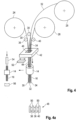
- FIG 4 is shown schematically how the device for producing the brush can be designed.
- the bristles are not taken from a magazine in which the bristles are already cut to length, but rather endless spools 24 to 28 are used for production, on which strands 30 to 34 of fibers arranged next to one another are rolled up.
- the fibers then later form the individual bristles. This will be explained in more detail later.
- the individual strands 30 to 34 are different in terms of color, number of fibers and/or diameter of the fibers.
- the fibers of strand 30 may be black and have a diameter of 0.1 mm, whereas the fibers of strand 32 are red and have a diameter of 0.05 mm, and the fibers of strand 34 could again be black with a diameter of 0.1 mm.
- These strands 30 to 34 are unrolled from the spools 24 to 28, for example by rollers 36 to 38 (and usually also corresponding counter rollers, which are not shown here for the sake of simplicity) engaging the respective strand 30 to 34 and unrolling it.
- the device for producing the brush has an introduction device 42 between the rollers 36 to 40 and the bundle carrier 14, which is shown in a simplified manner and in which the strands 30 to 34 are combined to form a common strand 44.
- the introduction device has an introduction channel 46 which has a rear (in Figure 4 visible) and an opposite mouth on the front.
- the mouths have different cross-sections.
- the rear mouth has a larger cross-section than the front mouth.
- other cross-sectional shapes can also be realized on the front and rear.
- the introduction channel 46 it has a channel section at the front that branches off into several sub-channels at the back. A strand 30 to 34 can then be threaded into each of these sub-channels and these strands 30 to 34 are brought together within the introduction device 42 when they reach the common channel section. This has the advantage that the position of the strands 30 to 34 is kept stable for a very long time in order to ensure that the individual fibers of the strands 30 to 34 are always aligned and positioned as identically as possible within the common strand 44.
- rollers 36 to 40 A variant of the rollers 36 to 40 is in Figure 4a can be seen, because here a roller 48, which is driven, is divided by disc-like partitions 50 into segments that define rollers 36 to 40.
- a common drive can be used, and in addition, the strands 30 to 34 are stably positioned before they enter the insertion device 42.
- the common strand 44 extends at the rear into the bundle carrier 14 and is pushed through it to the front so that the front end of the strand 44 protrudes from the bundle carrier 14.
- the strand 14 is severed at the rear of the bundle carrier 14 by a cutting device 52, so that the bristle bundle 16 is formed.
- the bristle bundle 16 is then transported further within the device and pushed deeper into the bundle carrier 14 by a plunger 54, which is part of the feed device, until the front end of the bristle bundle 16 rests against a stop 56.
- the individual rear bristle ends can then be fused together by a hot stamp or simply by applying heat, so that they form a kind of layer or lump within the bundle carrier 14.
- the stop 56 can, as in Figure 4 shown, to determine the shape of the tip of the bundle.
- the stop is then part of a so-called alignment tool for the bristle bundle 16.
- the alignment tool can alternatively be designed as a plate-shaped body with openings, wherein the opening cross-section and the orientation of the opening determine the orientation of the bristle bundle 16 and its cross-section.
- the alignment tool can be used similarly to the alignment tool 58 in Figure 10 in which the opening 60 is inclined and has an elongated contour in cross-section. However, this is only to be understood as an example.
- Figure 6 shows that the rollers 36, 36' can be profiled on their outer surfaces, for example by making one roller convex in cross section and one roller concave on its outer surface. This profiling gives the strand 30 a corresponding cross-section profile in the direction of movement after the rollers 36, 36' in order to be able to be more easily introduced into the corresponding opening in the bundle carrier 14.
- the profile of the strand 30 after the rollers 36, 36 ⁇ does not have to be the final profile of the later bristle bundle 16, but can take on an intermediate shape that is closer to the later shape than the cross section of the strand 30 before the rollers 36, 36 ⁇ .
- the outer bristles of the entire bristle bundle 16 may be thinner bristles or of a different color than the central bristles coming from the strand 32.
- the individual sub-bundles are arranged in a changing manner even more often.
- a fastening device 62 for fastening the bristle bundle 16 to the holding section, here to the bundle carrier 14, is symbolically shown.
- the fastening device 62 is designed here as a hot stamp which is pressed into the opening 18 from the rear side, so that a kind of lump 64 of melted bristle ends is formed, ie all bundles are connected to one another and thus also secured against being pulled out of the bundle carrier to the front.
- the feeding device formed by the rollers 36 to 40 can of course also be designed differently.
- the strand or strands can preferably be inserted into the bristle carrier perpendicular to its rear side.
- the bundle carrier 14 forms the holding section of the brush body and a is a separate, previously manufactured component
- the entire brush body or brush body is a prefabricated part into which the bundles are inserted.
- the mounting section is the section of the brush body in the area of the bundles.
- a toothbrush is stuffed which, as in all embodiments, has bundles of bristles 16 attached to it without anchors.
- the brush body 66 has a handle, neck and a head 68 with several openings 18 provided.
- the head 68 here forms the holding section for the bundles of bristles 16.
- the stuffing takes place on the back.
- the bundle carrier in this embodiment is a so-called intermediate magazine 70 which is reused in the device and into which strands are inserted from the spool(s) 24 to 28 into the magazine 70, which, after being inserted, are cut into bundles at the rear by the cutting device 32.
- the intermediate magazine 70 can have one or more openings 72.
- the intermediate magazine 70 preferably has the same hole pattern as the hole pattern of the holding section, which here simultaneously forms the brush body.
- the intermediate magazine 70 is thus completely filled with bundles 16. Strands can be fed from one or more spools 24 to 28 simultaneously or one after the other into different or identical openings in the intermediate magazine. This is all variable as desired.
- the intermediate magazine 70 is moved to the head 68, or vice versa, and the bristle bundles 16 are then pushed individually or together from the intermediate magazine into the opposite openings in the head 68, e.g. via corresponding plungers 54, which are part of the feed device.
- the brush body (intermediate magazine or plate as part of the complete brush body or brush body itself) has several openings, as in Figure 9 , these can be equipped with one or more spools with bundles of bristles which are then separated later.
- the bobbin/bobbins or the brush body are moved in two directions between the roller and the brush body, e.g. with or without the use of an insertion device 42, in order to achieve a relative movement of these parts. For example, one hole after the other is plugged with a bobbin and after the strand has been inserted it is cut off.
- strands and spools with different fibers can be used.
- three spools may be sufficient.
- Spools can also be switched on or off during a filling process of a brush body with multiple openings when their strand is no longer needed. Furthermore, strands can also be inserted one after the other into the same opening in the insertion device so that it positions different strands one after the other.
- strands can also be combined if large tufts need to be created in the brush. For example: for a toothbrush with 20 holes, it may be necessary to use 25 spools, where the strands from ten spools are combined into five common strands.
- the alignment tool 58 is located directly or slightly spaced apart from the front of the holder section, with corresponding channels or openings 74 into which the bristle bundles 16 extend.
- the cross-sectional shape and orientation of the openings 74 can then again determine the Define the orientation or profile of the bristle bundles 16 in the holder section.
- a possibly profiled stop 56 may also be present on the front.
- Figure 10 shows, using an example, how the alignment tool 58 defines the shape of the bundle of bristles 16 that is later pushed in.
- a bundle of bristles is to be introduced into the head 68, which is inclined on the one hand and has an elongated shape on the other.
- two bundles of bristles are combined within the holding section, here the head 68, so that the holding section simultaneously forms the insertion device, as is used, for example, in connection with Figure 4 was explained.
- the head 68 has an opening 18 which is at the front (in Figure 10 below) has a single opening with a specific cross-section. At the back, however, the opening splits into two partial openings 76, 78, which are separated from one another by an intermediate web 80. The opening 18 thus opens into two smaller partial openings 76, 78 with a different cross-section.
- Each partial opening 76, 78 or each corresponding opening is provided for a strand into which the hair is threaded directly.
- the strands are then cut off at the back, as explained in the previous figures.
- An insertion bevel 82 serves to deflect the common bundle of bristles into the obliquely positioned opening 60.
- the strands are not introduced directly into the holding section, here the head 68, but rather are stored in an intermediate magazine, as shown in Figure 9 shown, bundles of bristles are cut to length, which are then stuffed into the holder section and secured to the holder section.
- bristle bundles or strands can be inserted into insertion channels or openings that have a different mouth cross-section on the back than on the front, in order to facilitate the insertion of the On the one hand, to facilitate the profiling of the bristle bundle on the front side and, on the other hand, to ensure profiling of the bristle bundle on the front side or at least to support the profiling.
- FIG. 11 Such a variant of cross-sections at the mouths on the front and back is based on Figure 11 for a head 68 of a toothbrush, whereby corresponding variants can also be used for a bundle carrier 70 such as an intermediate magazine or for an insertion device 42.
- Each opening 18 is in Figure 11 represented with two lines, with a thick line symbolizing the mouth cross-section on the front and a thin line symbolizing the mouth cross-section of the corresponding opening 18 on the back.
- the mouths can also be defined by sections of the thick line if the thick line intersects the outer thin line towards the outside.
- Figure 12 is symbolically shown how individual or multiple bristle bundles 16 can be anchored in the bundle carrier 14.
- the lump 64 that is formed when the bristle ends melt is partially in the corresponding opening in the bundle carrier 14 in this embodiment.
- the melted material can also form a layer on the back.
- Figure 12 also shows at its right end that the mouths of the opening 18 have a different cross-section at the front and back, here the opening 18 tapers from the back to the front.
- the center points 84, 86 of the mouth cross-sections at the front and back are laterally offset from one another, as shown by the axis lines.
- the insertion channel 46 or the corresponding openings in the intermediate magazine can of course also have corresponding shapes.
- Figure 14 shows a bundle carrier, which can optionally also be designed as an intermediate magazine and which is an injection molding tool insert 90.
- Openings 18 are formed in this injection molding tool insert 90, into which the strands from the rollers can be either directly introduced, with or without an insertion device 42.
- the already cut bristle bundles can be fed via an intermediate magazine, as shown in Figure 9 shown, and then pushed into the openings 18.
- the injection mold insert 90 finally has bristle bundles protruding from the rear, which are then connected at the back, for example by melting.
- the equipped injection mold insert 90 is then placed in an injection mold half 92, see Figure 15 used, in which, in the example shown, which is not to be understood as limiting, partial cavities 94 are also provided for the handle of the brush.
- a corresponding upper mold half 96 can also have partial cavities.
- the rear ends of the bristle bundle are overmolded to form the brush body, which forms a holding section in the area of the bundle.
- the bristle bundles 16 can also be attached to a separate, previously manufactured component, namely a plate-like bundle carrier 14, which is then inserted into the corresponding cavity 98 in the injection mold insert 90 and is subsequently overmolded to form the remaining part of the brush body.
- a separate, previously manufactured component namely a plate-like bundle carrier 14, which is then inserted into the corresponding cavity 98 in the injection mold insert 90 and is subsequently overmolded to form the remaining part of the brush body.
Landscapes
- Engineering & Computer Science (AREA)
- Manufacturing & Machinery (AREA)
- Physics & Mathematics (AREA)
- Geometry (AREA)
- Brushes (AREA)
Claims (15)
- Procédé de fabrication d'une brosse ou d'un pinceau, en particulier d'un pinceau à peinture par la fixation sans ancrage d'au moins une touffe de poils (16) sur un tronçon de retenue de la brosse ou du pinceau,ladite au moins une touffe de poils (16) étant fixée sans ancrage sur le tronçon de retenue, etladite au moins une touffe de poils (16) à fixer dans la brosse ou le pinceau étant fabriquée au moyen des étapes suivantes :a) fournir un support de touffe (14) qui présente une face avant et une face arrière opposée et au moins une ouverture traversante (18) reliant la face avant et la face arrière,b) dérouler du matériau de poils d'au moins une bobine (24 - 28) sous forme de cordon (30 - 34) d'une pluralité de fibres agencées les unes à côté des autres,c) insérer le matériau de poils non coupé à longueur dans le support de touffe (14), en particulier depuis la face arrière et en particulier sensiblement perpendiculairement à la face arrière, etd) ensuite couper le matériau de poils en saillie dans le support de touffe (14) die manière à former une touffe de poils (16) réalisée dans le support de touffe, caractérisé en ce quele support de touffe (14) est le tronçon de retenue de la brosse ou du pinceau lui-même, le tronçon de retenue étant un tronçon se fondant d'un seul tenant dans le reste du corps de brosse ou de pinceau ou une pièce séparée fabriquée au préalable, laquelle fait partie du corps de brosse ou de pinceau ultérieur.
- Procédé selon la revendication 1, caractérisé en ce que des cordons (30 - 34) sont simultanément déroulés de plusieurs bobines (24 - 28) et sont réunis en un cordon commun (44) qui est inséré dans l'ouverture (18) du support de touffe (14) et est ensuite coupé, les cordons (30 - 34) se trouvant sur les bobines (24 - 28) étant en particulier différents les uns des autres.
- Procédé selon l'une des revendications précédentes, caractérisé en ce que la touffe de poils (16) est retenue sur ou dans le tronçon de retenue de sorte que dans une vue latérale par rapport aux poils ou dans une vue de dessus sur les poils, elle présente une extrémité de touffe avant en arc.
- Procédé selon l'une des revendications précédentes, caractérisé en ce qu'après l'étape d), la touffe de poils (16) coupée est déplacée plus loin à travers le support de touffe (14) en direction de la face avant.
- Procédé selon l'une des revendications précédentes, caractérisé en ce que le matériau de poil est inséré dans le support de touffe (14) jusqu'à faire saillie par rapport à la face avant.
- Procédé selon l'une des revendications précédentes, caractérisé en ce que les extrémités de poils en saille sur la face arrière sont fixées sur le tronçon de retenue, en particulier en ce que les extrémités de poils en saillie sur la face arrière sont fondues les unes avec les autres sur la face arrière après le passage à travers le tronçon de retenue.
- Procédé selon l'une des revendications précédentes, caractérisé en ce qu'après la fixation de la touffe de poils (16) sur le tronçon de retenue, le tronçon de retenue est fixé sur une poignée (12), une liaison par enclenchement étant en particulier prévue entre la poignée (12) et le support de poil (14).
- Dispositif de fabrication d'une brosse ou d'un pinceau, en particulier pour la réalisation du procédé selon l'une des revendications précédentes, caractérisé en ce qu'il est prévu un support de touffe (14) à équiper d'au moins une touffe de poils (16), lequel présente une face avant et une face arrière opposée ainsi qu'une ouverture traversante (18) reliant la face avant et la face arrière, le dispositif comprenant :au moins une bobine (24 - 28) sur laquelle est enroulé un cordon (30 - 34) formé par une pluralité de fibres sans fin agencées les unes à côté des autres,un dispositif d'amenée qui déroule le cordon (30 - 34) d'au moins une bobine (24 - 28) et l'insert dans l'ouverture dans le support de touffe (14) qui est le tronçon de retenue de la brosse ou du pinceau lui-même, le tronçon de retenue étant un tronçon se fondant d'un seul tenant dans le reste du corps de brosse ou de pinceau ou un composant séparé fabriqué au préalable, lequel fait partie du support de touffe (14) ultérieur,un dispositif de coupe (52) qui sépare une touffe de poils (16) du cordon (30 - 34) après l'insertion de l'extrémité du cordon dans l'ouverture (18),
etun dispositif de fixation (62) pour la fixation de la touffe de poils (16) sur un tronçon de retenue de la brosse ou du pinceau, en particulier un dispositif de fixation (62) sous forme de dispositif de fusion. - Dispositif selon la revendication 8, caractérisé en ce que le dispositif d'amenée comprend au moins un rouleau (36 - 40) qui s'engage sur le tronçon extrait du cordon (30 - 34) pour l'extraction du cordon (30 - 34), en particulier en ce que plusieurs rouleaux séparés (36 - 40) sont présents pour le déroulement de plusieurs cordons (30 - 34), ou en ce que des tronçons séparés les uns des autre sur un cylindre (48) forment les rouleaux (36 - 40), chaque rouleau (36 - 40) étant par exemple associé à un cordon (30 - 34) d'une bobine (24 - 28).
- Dispositif selon l'une des revendications 8 et 9, caractérisé en ce qu'entre la bobine (24 - 28) et le support de touffe (14), il est prévu un dispositif d'insertion (42) qui comprend au moins un canal d'insertion (46) dans lequel l'extrémité du cordon (30 - 34) est insérée en premier, et l'extrémité du canal d'insertion étant agencée en face de l'embouchure arrière de l'ouverture (18) sur le support de touffe (14), une pluralité de cordons (30 - 34) de plusieurs bobines (24 - 28) s'étendant en particulier à travers le dispositif d'insertion (42), et/ou en ce que plusieurs cordons (30 - 34) se réunissent en particulier en un cordon (44) du côté de la sortie dans le dispositif d'insertion (42).
- Dispositif selon l'une des revendications 8 à 10, caractérisé en ce que ledit au moins un canal d'insertion (46) ou l'ouverture (18) présente sur la face arrière une autre section transversale au niveau de l'embouchure que sur la face avant, en particulier en ce que le canal d'insertion (46) ou l'ouverture (18) s'effile de l'embouchure arrière vers l'embouchure avant et/ou l'embouchure avant et arrière ont différentes formes de section transversale.
- Dispositif selon l'une des revendications 8 à 11, caractérisé en ce qu'il est prévu plusieurs bobines (24 - 28) sur lesquelles des cordons (30 - 34) sont enroulés qui sont réunis pour former un cordon commun (44) ou qui sont insérés dans des ouvertures séparées (18) dans le support de touffe (14).
- Dispositif selon l'une des revendications 8 à 12, caractérisé en ce qu'il est prévu un outil d'alignement (58) au moyen duquel la forme de ladite au moins une touffe de poils (16) est déterminée, l'outil d'alignement (58) étant agencé sur la face avant du tronçon de retenue.
- Dispositif selon l'une des revendications 8 à 13, caractérisé en ce que le support de touffe (14) est un magasin intermédiaire (50) réutilisé dans le dispositif, qui est équipé de ladite au moins une touffe de poils (16) coupée à longueur et à partir duquel ladite au moins une touffe de poils (16) est en particulier poussée dans le tronçon de retenue et est ensuite fixée sur le tronçon de retenue, ou en ce que le magasin intermédiaire (50) est un insert d'outil de moulage par injection (90) pour la fabrication au moins de la partie du corps de brosse ou de pinceau formant le tronçon de retenue, ou en ce que ladite au moins une touffe de poils (16) est apte à être déplacée dans un insert d'outil de moulage par injection (90) par le magasin intermédiaire (50).
- Dispositif selon l'une des revendications 8 à 14, caractérisé en ce que le dispositif est réalisé de telle sorte que le dispositif d'amenée pousse la touffe de poils séparée plus loin dans le tronçon de retenue.
Applications Claiming Priority (2)
| Application Number | Priority Date | Filing Date | Title |
|---|---|---|---|
| BE2014/5156A BE1022487B1 (de) | 2014-12-23 | 2014-12-23 | Verfahren zum Herstellen einer Bürste oder eines Pinsels sowie Vorrichtung hierfür |
| PCT/EP2015/079539 WO2016102221A1 (fr) | 2014-12-23 | 2015-12-14 | Procédé de fabrication d'une brosse ou d'un pinceau ainsi que dispositif à cette fin |
Publications (2)
| Publication Number | Publication Date |
|---|---|
| EP3236806A1 EP3236806A1 (fr) | 2017-11-01 |
| EP3236806B1 true EP3236806B1 (fr) | 2024-08-21 |
Family
ID=52813850
Family Applications (1)
| Application Number | Title | Priority Date | Filing Date |
|---|---|---|---|
| EP15808611.6A Active EP3236806B1 (fr) | 2014-12-23 | 2015-12-14 | Procédé de fabrication d'une brosse ou d'un pinceau ainsi que dispositif à cette fin |
Country Status (4)
| Country | Link |
|---|---|
| EP (1) | EP3236806B1 (fr) |
| BE (1) | BE1022487B1 (fr) |
| TW (1) | TWI675632B (fr) |
| WO (1) | WO2016102221A1 (fr) |
Cited By (1)
| Publication number | Priority date | Publication date | Assignee | Title |
|---|---|---|---|---|
| DE102024110543A1 (de) * | 2024-04-15 | 2025-10-16 | Zahoransky Ag | Transportplatte für Borstenfilamente, Transportvorrichtung und Borstenwarenherstellungsmaschine |
Families Citing this family (6)
| Publication number | Priority date | Publication date | Assignee | Title |
|---|---|---|---|---|
| DE102017106531A1 (de) * | 2017-03-27 | 2018-09-27 | Gb Boucherie Nv | Verfahren und Vorrichtung sowie Spritzgussformhälftenteil zum Herstellen einer Bürste |
| BE1024476B1 (de) * | 2017-03-27 | 2018-04-24 | Bart Gerard Boucherie | Verfahren und Vorrichtung sowie Spritzgussformhälftenteil zum Herstellen einer Bürste |
| CN109965502B (zh) * | 2019-03-12 | 2020-07-07 | 安徽环美刷业有限公司 | 一种毛刷制造用捆丝装置 |
| EP3750442B1 (fr) * | 2019-06-13 | 2026-02-11 | Trisa Holding AG | Dispositif applicateur |
| DE102020111870B3 (de) * | 2020-04-30 | 2021-07-15 | Gb Boucherie Nv | Verfahren und Vorrichtung zum Herstellen einer Rundbürste |
| DE202020103678U1 (de) * | 2020-06-25 | 2020-07-07 | Gb Boucherie Nv | Schlingenwerkzeugspitze, Führungsbacke hierfür sowie Bürstenstopfvorrichtung |
Family Cites Families (4)
| Publication number | Priority date | Publication date | Assignee | Title |
|---|---|---|---|---|
| FR2687055B1 (fr) * | 1992-02-11 | 1994-04-29 | Oreal | Pinceau pour l'application de vernis a ongles, ou de produit similaire. |
| DE10005249A1 (de) * | 2000-02-05 | 2001-08-09 | Zahoransky Anton Gmbh & Co | Bürstenherstellungsmaschine |
| DE102009053663A1 (de) * | 2009-11-17 | 2011-05-19 | Zahoransky Ag | Kleben von kalibrierten Bündel |
| KR101284141B1 (ko) * | 2011-10-10 | 2013-07-10 | 최태용 | 매니큐어 화장솔 제조방법 및 이에 의해 제조된 화장솔 |
-
2014
- 2014-12-23 BE BE2014/5156A patent/BE1022487B1/de not_active IP Right Cessation
-
2015
- 2015-12-14 WO PCT/EP2015/079539 patent/WO2016102221A1/fr not_active Ceased
- 2015-12-14 EP EP15808611.6A patent/EP3236806B1/fr active Active
- 2015-12-23 TW TW104143442A patent/TWI675632B/zh active
Cited By (2)
| Publication number | Priority date | Publication date | Assignee | Title |
|---|---|---|---|---|
| DE102024110543A1 (de) * | 2024-04-15 | 2025-10-16 | Zahoransky Ag | Transportplatte für Borstenfilamente, Transportvorrichtung und Borstenwarenherstellungsmaschine |
| BE1032500A1 (de) | 2024-04-15 | 2025-10-27 | Zahoransky Ag | Transportplatte für Borstenfilamente, Transportvorrichtung und Borstenwarenherstellungsmaschine |
Also Published As
| Publication number | Publication date |
|---|---|
| WO2016102221A1 (fr) | 2016-06-30 |
| BE1022487B1 (de) | 2016-05-04 |
| TWI675632B (zh) | 2019-11-01 |
| TW201633961A (zh) | 2016-10-01 |
| EP3236806A1 (fr) | 2017-11-01 |
Similar Documents
| Publication | Publication Date | Title |
|---|---|---|
| BE1022487B1 (de) | Verfahren zum Herstellen einer Bürste oder eines Pinsels sowie Vorrichtung hierfür | |
| EP2605682B1 (fr) | Brosse à dents avec des touffes orientées asymétriquement | |
| EP1158880B1 (fr) | Procede et dispositif pour produire des articles de brosserie et articles de brosserie ainsi obtenus | |
| EP0193074B1 (fr) | Procédé et dispositif pour fabriquer des articles de brosserie | |
| EP1864588B1 (fr) | Brosse à dents et procédé destiné à sa fabrication | |
| DE4311186A1 (de) | Verfahren und Vorrichtung zur Herstellung von Bürstenwaren | |
| EP2587959B2 (fr) | Procédé et dispositif de production de brosses | |
| DE102012008536B4 (de) | Verfahren zum Herstellen von Bürsten sowie Bürste | |
| DE102009021482B4 (de) | Verfahren und Vorrichtung zum Herstellen von Bürsten | |
| DE102011013621B4 (de) | Verfahren und Vorrichtung zum Herstellen von Bürsten | |
| EP2377424B1 (fr) | Dispositif et procédé de fabrication de brosses | |
| EP3599933B1 (fr) | Procédé, dispositif et élément de demi-moule pour moulage par injection servant à fabriquer une brosse | |
| DE102012010415B4 (de) | Verfahren zum Herstellen von Bürsten, Borstenträger sowie Bürste | |
| DE3719823C1 (de) | Verfahren und Vorrichtung zur Herstellung von Borstenwaren sowie Anwendung des Verfahrens fuer Geraete aehnlichen Aufbaus | |
| DE102014002960A1 (de) | Verfahren und Vorrichtung zum Herstellen von Bürsten | |
| EP2841248B1 (fr) | Outil de moulage par injection d'un support de brosse | |
| DE10108339A1 (de) | Verfahren zur Herstellung von Bürsten im Wege des Spritzgießens | |
| DE102011017099A1 (de) | Verfahren zur Herstellung von Zahnbürsten | |
| DE102005004661B4 (de) | Verfahren und Maschine zum Herstellen von Bürsten | |
| DE102007006361B3 (de) | Verfahren und Vorrichtung zur Herstellung von Pinseln sowie Pinsel | |
| EP2763567B1 (fr) | Procédé et dispositif pour la fabrication de brosses et brosse | |
| WO1993021795A1 (fr) | Procede de fabrication de pinceaux au moyen d'une machine et dispositif approprie | |
| DE10017465B4 (de) | Verfahren und Vorrichtung zur Herstellung von Borstenwaren | |
| DE19949772A1 (de) | Verfahren und Vorrichtung zur Herstellung einer Bürste |
Legal Events
| Date | Code | Title | Description |
|---|---|---|---|
| STAA | Information on the status of an ep patent application or granted ep patent |
Free format text: STATUS: THE INTERNATIONAL PUBLICATION HAS BEEN MADE |
|
| PUAI | Public reference made under article 153(3) epc to a published international application that has entered the european phase |
Free format text: ORIGINAL CODE: 0009012 |
|
| STAA | Information on the status of an ep patent application or granted ep patent |
Free format text: STATUS: REQUEST FOR EXAMINATION WAS MADE |
|
| 17P | Request for examination filed |
Effective date: 20170721 |
|
| AK | Designated contracting states |
Kind code of ref document: A1 Designated state(s): AL AT BE BG CH CY CZ DE DK EE ES FI FR GB GR HR HU IE IS IT LI LT LU LV MC MK MT NL NO PL PT RO RS SE SI SK SM TR |
|
| AX | Request for extension of the european patent |
Extension state: BA ME |
|
| DAV | Request for validation of the european patent (deleted) | ||
| DAX | Request for extension of the european patent (deleted) | ||
| STAA | Information on the status of an ep patent application or granted ep patent |
Free format text: STATUS: EXAMINATION IS IN PROGRESS |
|
| 17Q | First examination report despatched |
Effective date: 20210707 |
|
| GRAP | Despatch of communication of intention to grant a patent |
Free format text: ORIGINAL CODE: EPIDOSNIGR1 |
|
| STAA | Information on the status of an ep patent application or granted ep patent |
Free format text: STATUS: GRANT OF PATENT IS INTENDED |
|
| INTG | Intention to grant announced |
Effective date: 20240405 |
|
| GRAS | Grant fee paid |
Free format text: ORIGINAL CODE: EPIDOSNIGR3 |
|
| GRAA | (expected) grant |
Free format text: ORIGINAL CODE: 0009210 |
|
| STAA | Information on the status of an ep patent application or granted ep patent |
Free format text: STATUS: THE PATENT HAS BEEN GRANTED |
|
| AK | Designated contracting states |
Kind code of ref document: B1 Designated state(s): AL AT BE BG CH CY CZ DE DK EE ES FI FR GB GR HR HU IE IS IT LI LT LU LV MC MK MT NL NO PL PT RO RS SE SI SK SM TR |
|
| P01 | Opt-out of the competence of the unified patent court (upc) registered |
Free format text: CASE NUMBER: APP_42144/2024 Effective date: 20240717 |
|
| REG | Reference to a national code |
Ref country code: GB Ref legal event code: FG4D Free format text: NOT ENGLISH |
|
| REG | Reference to a national code |
Ref country code: CH Ref legal event code: EP |
|
| REG | Reference to a national code |
Ref country code: IE Ref legal event code: FG4D Free format text: LANGUAGE OF EP DOCUMENT: GERMAN |
|
| REG | Reference to a national code |
Ref country code: DE Ref legal event code: R096 Ref document number: 502015016928 Country of ref document: DE |
|
| REG | Reference to a national code |
Ref country code: LT Ref legal event code: MG9D |
|
| REG | Reference to a national code |
Ref country code: NL Ref legal event code: MP Effective date: 20240821 |
|
| PG25 | Lapsed in a contracting state [announced via postgrant information from national office to epo] |
Ref country code: NO Free format text: LAPSE BECAUSE OF FAILURE TO SUBMIT A TRANSLATION OF THE DESCRIPTION OR TO PAY THE FEE WITHIN THE PRESCRIBED TIME-LIMIT Effective date: 20241121 |
|
| PG25 | Lapsed in a contracting state [announced via postgrant information from national office to epo] |
Ref country code: FI Free format text: LAPSE BECAUSE OF FAILURE TO SUBMIT A TRANSLATION OF THE DESCRIPTION OR TO PAY THE FEE WITHIN THE PRESCRIBED TIME-LIMIT Effective date: 20240821 Ref country code: GR Free format text: LAPSE BECAUSE OF FAILURE TO SUBMIT A TRANSLATION OF THE DESCRIPTION OR TO PAY THE FEE WITHIN THE PRESCRIBED TIME-LIMIT Effective date: 20241122 Ref country code: NL Free format text: LAPSE BECAUSE OF FAILURE TO SUBMIT A TRANSLATION OF THE DESCRIPTION OR TO PAY THE FEE WITHIN THE PRESCRIBED TIME-LIMIT Effective date: 20240821 Ref country code: PT Free format text: LAPSE BECAUSE OF FAILURE TO SUBMIT A TRANSLATION OF THE DESCRIPTION OR TO PAY THE FEE WITHIN THE PRESCRIBED TIME-LIMIT Effective date: 20241223 Ref country code: PL Free format text: LAPSE BECAUSE OF FAILURE TO SUBMIT A TRANSLATION OF THE DESCRIPTION OR TO PAY THE FEE WITHIN THE PRESCRIBED TIME-LIMIT Effective date: 20240821 |
|
| PG25 | Lapsed in a contracting state [announced via postgrant information from national office to epo] |
Ref country code: BG Free format text: LAPSE BECAUSE OF FAILURE TO SUBMIT A TRANSLATION OF THE DESCRIPTION OR TO PAY THE FEE WITHIN THE PRESCRIBED TIME-LIMIT Effective date: 20240821 |
|
| PG25 | Lapsed in a contracting state [announced via postgrant information from national office to epo] |
Ref country code: LV Free format text: LAPSE BECAUSE OF FAILURE TO SUBMIT A TRANSLATION OF THE DESCRIPTION OR TO PAY THE FEE WITHIN THE PRESCRIBED TIME-LIMIT Effective date: 20240821 |
|
| PG25 | Lapsed in a contracting state [announced via postgrant information from national office to epo] |
Ref country code: IS Free format text: LAPSE BECAUSE OF FAILURE TO SUBMIT A TRANSLATION OF THE DESCRIPTION OR TO PAY THE FEE WITHIN THE PRESCRIBED TIME-LIMIT Effective date: 20241221 |
|
| PG25 | Lapsed in a contracting state [announced via postgrant information from national office to epo] |
Ref country code: HR Free format text: LAPSE BECAUSE OF FAILURE TO SUBMIT A TRANSLATION OF THE DESCRIPTION OR TO PAY THE FEE WITHIN THE PRESCRIBED TIME-LIMIT Effective date: 20240821 |
|
| PG25 | Lapsed in a contracting state [announced via postgrant information from national office to epo] |
Ref country code: ES Free format text: LAPSE BECAUSE OF FAILURE TO SUBMIT A TRANSLATION OF THE DESCRIPTION OR TO PAY THE FEE WITHIN THE PRESCRIBED TIME-LIMIT Effective date: 20240821 Ref country code: RS Free format text: LAPSE BECAUSE OF FAILURE TO SUBMIT A TRANSLATION OF THE DESCRIPTION OR TO PAY THE FEE WITHIN THE PRESCRIBED TIME-LIMIT Effective date: 20241121 |
|
| PG25 | Lapsed in a contracting state [announced via postgrant information from national office to epo] |
Ref country code: RS Free format text: LAPSE BECAUSE OF FAILURE TO SUBMIT A TRANSLATION OF THE DESCRIPTION OR TO PAY THE FEE WITHIN THE PRESCRIBED TIME-LIMIT Effective date: 20241121 Ref country code: PT Free format text: LAPSE BECAUSE OF FAILURE TO SUBMIT A TRANSLATION OF THE DESCRIPTION OR TO PAY THE FEE WITHIN THE PRESCRIBED TIME-LIMIT Effective date: 20241223 Ref country code: PL Free format text: LAPSE BECAUSE OF FAILURE TO SUBMIT A TRANSLATION OF THE DESCRIPTION OR TO PAY THE FEE WITHIN THE PRESCRIBED TIME-LIMIT Effective date: 20240821 Ref country code: NO Free format text: LAPSE BECAUSE OF FAILURE TO SUBMIT A TRANSLATION OF THE DESCRIPTION OR TO PAY THE FEE WITHIN THE PRESCRIBED TIME-LIMIT Effective date: 20241121 Ref country code: NL Free format text: LAPSE BECAUSE OF FAILURE TO SUBMIT A TRANSLATION OF THE DESCRIPTION OR TO PAY THE FEE WITHIN THE PRESCRIBED TIME-LIMIT Effective date: 20240821 Ref country code: LV Free format text: LAPSE BECAUSE OF FAILURE TO SUBMIT A TRANSLATION OF THE DESCRIPTION OR TO PAY THE FEE WITHIN THE PRESCRIBED TIME-LIMIT Effective date: 20240821 Ref country code: IS Free format text: LAPSE BECAUSE OF FAILURE TO SUBMIT A TRANSLATION OF THE DESCRIPTION OR TO PAY THE FEE WITHIN THE PRESCRIBED TIME-LIMIT Effective date: 20241221 Ref country code: HR Free format text: LAPSE BECAUSE OF FAILURE TO SUBMIT A TRANSLATION OF THE DESCRIPTION OR TO PAY THE FEE WITHIN THE PRESCRIBED TIME-LIMIT Effective date: 20240821 Ref country code: GR Free format text: LAPSE BECAUSE OF FAILURE TO SUBMIT A TRANSLATION OF THE DESCRIPTION OR TO PAY THE FEE WITHIN THE PRESCRIBED TIME-LIMIT Effective date: 20241122 Ref country code: FI Free format text: LAPSE BECAUSE OF FAILURE TO SUBMIT A TRANSLATION OF THE DESCRIPTION OR TO PAY THE FEE WITHIN THE PRESCRIBED TIME-LIMIT Effective date: 20240821 Ref country code: ES Free format text: LAPSE BECAUSE OF FAILURE TO SUBMIT A TRANSLATION OF THE DESCRIPTION OR TO PAY THE FEE WITHIN THE PRESCRIBED TIME-LIMIT Effective date: 20240821 Ref country code: BG Free format text: LAPSE BECAUSE OF FAILURE TO SUBMIT A TRANSLATION OF THE DESCRIPTION OR TO PAY THE FEE WITHIN THE PRESCRIBED TIME-LIMIT Effective date: 20240821 |
|
| PG25 | Lapsed in a contracting state [announced via postgrant information from national office to epo] |
Ref country code: SM Free format text: LAPSE BECAUSE OF FAILURE TO SUBMIT A TRANSLATION OF THE DESCRIPTION OR TO PAY THE FEE WITHIN THE PRESCRIBED TIME-LIMIT Effective date: 20240821 Ref country code: DK Free format text: LAPSE BECAUSE OF FAILURE TO SUBMIT A TRANSLATION OF THE DESCRIPTION OR TO PAY THE FEE WITHIN THE PRESCRIBED TIME-LIMIT Effective date: 20240821 Ref country code: RO Free format text: LAPSE BECAUSE OF FAILURE TO SUBMIT A TRANSLATION OF THE DESCRIPTION OR TO PAY THE FEE WITHIN THE PRESCRIBED TIME-LIMIT Effective date: 20240821 |
|
| PG25 | Lapsed in a contracting state [announced via postgrant information from national office to epo] |
Ref country code: EE Free format text: LAPSE BECAUSE OF FAILURE TO SUBMIT A TRANSLATION OF THE DESCRIPTION OR TO PAY THE FEE WITHIN THE PRESCRIBED TIME-LIMIT Effective date: 20240821 |
|
| PG25 | Lapsed in a contracting state [announced via postgrant information from national office to epo] |
Ref country code: CZ Free format text: LAPSE BECAUSE OF FAILURE TO SUBMIT A TRANSLATION OF THE DESCRIPTION OR TO PAY THE FEE WITHIN THE PRESCRIBED TIME-LIMIT Effective date: 20240821 |
|
| PG25 | Lapsed in a contracting state [announced via postgrant information from national office to epo] |
Ref country code: SK Free format text: LAPSE BECAUSE OF FAILURE TO SUBMIT A TRANSLATION OF THE DESCRIPTION OR TO PAY THE FEE WITHIN THE PRESCRIBED TIME-LIMIT Effective date: 20240821 |
|
| REG | Reference to a national code |
Ref country code: DE Ref legal event code: R097 Ref document number: 502015016928 Country of ref document: DE |
|
| PLBE | No opposition filed within time limit |
Free format text: ORIGINAL CODE: 0009261 |
|
| STAA | Information on the status of an ep patent application or granted ep patent |
Free format text: STATUS: NO OPPOSITION FILED WITHIN TIME LIMIT |
|
| PG25 | Lapsed in a contracting state [announced via postgrant information from national office to epo] |
Ref country code: MC Free format text: LAPSE BECAUSE OF FAILURE TO SUBMIT A TRANSLATION OF THE DESCRIPTION OR TO PAY THE FEE WITHIN THE PRESCRIBED TIME-LIMIT Effective date: 20240821 |
|
| 26N | No opposition filed |
Effective date: 20250522 |
|
| PG25 | Lapsed in a contracting state [announced via postgrant information from national office to epo] |
Ref country code: LU Free format text: LAPSE BECAUSE OF NON-PAYMENT OF DUE FEES Effective date: 20241214 |
|
| GBPC | Gb: european patent ceased through non-payment of renewal fee |
Effective date: 20241214 |
|
| PG25 | Lapsed in a contracting state [announced via postgrant information from national office to epo] |
Ref country code: SE Free format text: LAPSE BECAUSE OF FAILURE TO SUBMIT A TRANSLATION OF THE DESCRIPTION OR TO PAY THE FEE WITHIN THE PRESCRIBED TIME-LIMIT Effective date: 20240821 |
|
| PG25 | Lapsed in a contracting state [announced via postgrant information from national office to epo] |
Ref country code: GB Free format text: LAPSE BECAUSE OF NON-PAYMENT OF DUE FEES Effective date: 20241214 |
|
| PG25 | Lapsed in a contracting state [announced via postgrant information from national office to epo] |
Ref country code: FR Free format text: LAPSE BECAUSE OF NON-PAYMENT OF DUE FEES Effective date: 20241231 |
|
| PG25 | Lapsed in a contracting state [announced via postgrant information from national office to epo] |
Ref country code: IE Free format text: LAPSE BECAUSE OF NON-PAYMENT OF DUE FEES Effective date: 20241214 |
|
| REG | Reference to a national code |
Ref country code: CH Ref legal event code: U11 Free format text: ST27 STATUS EVENT CODE: U-0-0-U10-U11 (AS PROVIDED BY THE NATIONAL OFFICE) Effective date: 20260101 |
|
| PGFP | Annual fee paid to national office [announced via postgrant information from national office to epo] |
Ref country code: DE Payment date: 20251119 Year of fee payment: 11 |
|
| PGFP | Annual fee paid to national office [announced via postgrant information from national office to epo] |
Ref country code: IT Payment date: 20251223 Year of fee payment: 11 |
|
| PGFP | Annual fee paid to national office [announced via postgrant information from national office to epo] |
Ref country code: BE Payment date: 20251219 Year of fee payment: 11 |
|
| REG | Reference to a national code |
Ref country code: AT Ref legal event code: MM01 Ref document number: 1714612 Country of ref document: AT Kind code of ref document: T Effective date: 20241214 |
|
| PG25 | Lapsed in a contracting state [announced via postgrant information from national office to epo] |
Ref country code: AT Free format text: LAPSE BECAUSE OF NON-PAYMENT OF DUE FEES Effective date: 20241214 |
|
| PGFP | Annual fee paid to national office [announced via postgrant information from national office to epo] |
Ref country code: CH Payment date: 20260101 Year of fee payment: 11 |