EP3243981A1 - Serrure - Google Patents
Serrure Download PDFInfo
- Publication number
- EP3243981A1 EP3243981A1 EP17169778.2A EP17169778A EP3243981A1 EP 3243981 A1 EP3243981 A1 EP 3243981A1 EP 17169778 A EP17169778 A EP 17169778A EP 3243981 A1 EP3243981 A1 EP 3243981A1
- Authority
- EP
- European Patent Office
- Prior art keywords
- lock
- latch
- additional locking
- locking element
- gear
- Prior art date
- Legal status (The legal status is an assumption and is not a legal conclusion. Google has not performed a legal analysis and makes no representation as to the accuracy of the status listed.)
- Granted
Links
Images


Classifications
-
- E—FIXED CONSTRUCTIONS
- E05—LOCKS; KEYS; WINDOW OR DOOR FITTINGS; SAFES
- E05B—LOCKS; ACCESSORIES THEREFOR; HANDCUFFS
- E05B63/00—Locks or fastenings with special structural characteristics
- E05B63/14—Arrangement of several locks or locks with several bolts, e.g. arranged one behind the other
- E05B63/146—Arrangement of several locks or locks with several bolts, e.g. arranged one behind the other locks with two or more bolts, each bolt itself being a tumbler
-
- E—FIXED CONSTRUCTIONS
- E05—LOCKS; KEYS; WINDOW OR DOOR FITTINGS; SAFES
- E05C—BOLTS OR FASTENING DEVICES FOR WINGS, SPECIALLY FOR DOORS OR WINDOWS
- E05C9/00—Arrangements of simultaneously actuated bolts or other securing devices at well-separated positions on the same wing
- E05C9/02—Arrangements of simultaneously actuated bolts or other securing devices at well-separated positions on the same wing with one sliding bar for fastening when moved in one direction and unfastening when moved in opposite direction; with two sliding bars moved in the same direction when fastening or unfastening
-
- E—FIXED CONSTRUCTIONS
- E05—LOCKS; KEYS; WINDOW OR DOOR FITTINGS; SAFES
- E05B—LOCKS; ACCESSORIES THEREFOR; HANDCUFFS
- E05B15/00—Other details of locks; Parts for engagement by bolts of fastening devices
- E05B15/004—Lost motion connections
-
- E—FIXED CONSTRUCTIONS
- E05—LOCKS; KEYS; WINDOW OR DOOR FITTINGS; SAFES
- E05B—LOCKS; ACCESSORIES THEREFOR; HANDCUFFS
- E05B15/00—Other details of locks; Parts for engagement by bolts of fastening devices
- E05B15/10—Bolts of locks or night latches
- E05B15/108—Bolts with multiple head
-
- E—FIXED CONSTRUCTIONS
- E05—LOCKS; KEYS; WINDOW OR DOOR FITTINGS; SAFES
- E05B—LOCKS; ACCESSORIES THEREFOR; HANDCUFFS
- E05B17/00—Accessories in connection with locks
- E05B17/20—Means independent of the locking mechanism for preventing unauthorised opening, e.g. for securing the bolt in the fastening position
- E05B17/2084—Means to prevent forced opening by attack, tampering or jimmying
-
- E—FIXED CONSTRUCTIONS
- E05—LOCKS; KEYS; WINDOW OR DOOR FITTINGS; SAFES
- E05B—LOCKS; ACCESSORIES THEREFOR; HANDCUFFS
- E05B65/00—Locks or fastenings for special use
- E05B65/10—Locks or fastenings for special use for panic or emergency doors
- E05B65/1086—Locks with panic function, e.g. allowing opening from the inside without a ley even when locked from the outside
Definitions
- the present invention relates to a lock having a plurality of locking elements, each movable between an extended locking position and a retracted release position.
- the additional locks are coupled with the provided for actuating the main lock mechanism lock that both a respective locking movement and a respective unlocking movement of the lock is transmitted directly to the additional locking elements.
- the connection of the additional locking elements with the associated connecting elements is therefore rigid in the known locks, with the result that in a manipulation of any additional locking element always the remaining locking elements can be moved with.
- the complete lock is disabled.
- the invention is therefore based on the object to provide a lock of the type mentioned, which ensures both a higher protection against manipulation and a more reliable locking.
- the lock according to the invention comprises a plurality of locking elements which are each movable between an extended locking position and a retracted release position, wherein the locking elements comprise a main locking element which can be actuated via a lock transmission arranged in a lock case and at least one additional locking element.
- a respective additional locking element is biased by spring force in its extended locking position and only in the opening direction in which it is moved against the spring force from its extended locking position to its retracted release position, acted upon via a positive connection by the lock gear.
- the individual additional locking elements are decoupled both from the main locking element and with each other so that is excluded in a manipulation of any additional locking element that at the same time also a further locking element is moved.
- the security against manipulation from the outside in the event of a break-in attempt is thus increased.
- a safer locking of the lock is achieved by the decoupling of the locking elements according to the invention.
- even a secure locking is ensured if a few locking elements are defective and clamp, for example, as a result of a distorted door leaf. Due to the inventive decoupling of the locking elements thus the functionality of the remaining locking elements is maintained even in the case of some defective locking elements.
- a respective additional locking element with the lock gear is imposed either only train or only on thrust, so that it can be acted upon by the lock gear via a pulling movement or a pushing movement in the opening direction and in the opposite direction is a freewheel.
- a respective additional locking element can be acted upon by the lock gear only in the pulling direction or only in the thrust direction to be moved against the spring force in the opening direction, while in the opposite direction is a freewheel, the connection of the additional locking element to the Lock mechanism only in one direction, namely in the opening direction instead, whereby the decoupling is ensured by the remaining locking elements.
- main locking element can be actuated via a lock transmission element, such as, in particular, a lock slide or the like, then a respective additional locking element is preferably only applied to the lock transmission element in tension or only in thrust.
- a lock transmission element such as, in particular, a lock slide or the like
- main locking element on the relevant lock transmission element or castle backdrop is preferably operable both in the opening direction and in the closing direction, a respective additional locking element is imposed with this lock transmission element only in the opening direction, in which it can be acted upon either by a pulling movement or by a pushing movement.
- a respective additional locking element can in particular be acted upon in the opening direction by the lock transmission via a connecting element assigned to it.
- the connecting element assigned to a respective additional locking element with the lock transmission or the lock transmission element is preferably imposed only on train or only on thrust.
- a plurality of additional locking elements can be actuated simultaneously via a respective lock transmission element such as, for example, a slide gate or the like, wherein it is once again ensured that the additional locking elements are decoupled both relative to the main locking element and one another in the described manner, i. each acted upon only in the opening direction by the lock gear or the lock gear element and are biased by spring force in the locking position.
- a respective lock transmission element such as, for example, a slide gate or the like
- the two additional locking elements which can be acted upon in the opening direction via a common lock transmission element can be connected to the lock transmission or lock transmission element in a plane or else offset from one another.
- a relatively staggered connection of the additional locking elements to the lock transmission element has the advantage that space for other components arises.
- one of the two additional locking elements or the connecting element assigned thereto is connected to the lock transmission or the lock transmission element via a cranked intermediate element.
- the main locking element is preferably stored in the lock case and the additional locking elements, each in its own lock box.
- the lock comprises at least one cross latch, which can be arranged adjacent to the main locking element. Additionally or alternatively, in each case at least one cross latch can be arranged adjacent to the additional locking elements.
- the at least one cross latch each comprises a first latch element and a second latch element, which are arranged pivotable relative to one another.
- the first latch member and the second latch member of the cross latch can be supported in the swung-out state on opposite inner sides of a recess in the strike plate, in which engage the main locking element and / or the additional locking elements in the excluded state and the latch elements in the swung-out state. In order for a jam-free bar exclusion of the main locking element and / or the additional locking elements is ensured even under pre-load.
- the at least one cross latch can be embodied, for example, as a split cross latch, which comprises a first cross-latch element arranged above the main latch element and / or the additional latch element and a second cross-latch element arranged below the main latch element and / or the additional latch element.
- a first cross-latch may be disposed above the main latch member, and a second latch may be disposed below the main latch member. Additionally or alternatively, a first cross-latch can be arranged above the respective additional locking element, and a second cross-latch can be arranged below the respective additional locking element.
- the lock can also be designed as a panic lock for an escape and rescue route. It can be ensured in particular by the relevant panic function that with the depression of a handle such as a door handle or the like all locking elements and traps are withdrawn into the castle, whereby the previously closed door is released immediately.
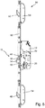
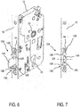
- Fig. 1 to 7 show a schematic representation of exemplary embodiments of a lock 10 according to the invention with a plurality of locking elements 14, 14 A, 48, 50, which are each movable between an extended locking position and a retracted release position.
- the lock 10 may be provided with a lock cylinder 20 and a follower 22 (see. Fig. 1 and 5 ).
- the lock 10 may for example be designed as a purely mechanical, self-locking lock and be equipped with a panic function, the lock 10 is unlocked from one side at any time by pressing a pusher, while from the other side opening the lock only on the lock cylinder 20 is possible ,
- the lock 10 may for example also be equipped with a split pusher nut 22 which is electromagnetically or electromechanically actuated. It is thus possible to decouple the pusher of a lock side of the opening mechanism, whereby the access can be controlled in a secure area.
- the lock 10 may for example also be operated by a motor.
- the locking elements 14, 14A, 48, 50 comprise a via a arranged in a lock case 12 lock gear 24 in particular both in the locking direction and unlocking acted upon main locking element 14, 14A and additional locking elements 48, 50.
- a respective additional locking element 48, 50 by spring force in its extended locking position biased and only in the opening direction, in which it is against the spring force from its extended locking position is moved into its retracted release position, acted upon by a positive connection by the lock gear 24.
- the additional locking elements 48, 50 are thus each moved only by spring force in its extended locking position.
- the additional locking elements 48, 50 are thus decoupled from the main locking element 14, 14A and each other so that in the case of a manipulation of the additional locking elements 48, 50 prevents that at the same time still another locking element is moved in the opening direction.
- the main locking element 14 as well as an auxiliary latch 44 is mounted in the lock case 12.
- a respective additional locking element 48, 50 may be imposed with the lock gear 24 either only train or only thrust, so that it can be acted upon by the lock gear 24 via a pulling movement or a pushing movement in the opening direction 26 and in the opposite direction Freewheel is present.
- the main locking element 14, 14A via a lock transmission element 28 in particular a castle backdrop or the like actuated and a respective additional locking element 48, 50 imposed with the lock gear member 28 only to train or only to push, so that it by this lock gear member 28 only in Pulling direction or only in the thrust direction and thus only in the opening direction 26 can be acted upon.
- a respective additional locking element 48, 50 can be acted upon by a connecting element 30, 32 associated therewith by the lock transmission element 28 in the opening direction 26.
- that is associated with a respective additional locking element 48, 50 Connecting element 30, 32 imposed with the lock transmission element 28 only on train or only on thrust.
- a respective additional locking element 50 and the associated therewith connecting element 32 may be provided for engagement with the lock gear member 28 only on thrust with a recess 34 open on one side, in which a lock gear member 28 associated approach 36 until it rests against the floor 38th the recess 34 is displaceable.
- a hook-slot connection can be provided (see. Fig. 4 ), in the present case, for example, the lock transmission element 28 is provided with a hook 40.
- an additional locking element 48 may be imposed with an end portion of the lock gear 24 and lock gear member 28 only to train and another additional locking element 50 with an opposite end portion of the lock gear 24 and lock gear member 28 only on thrust.
- the two additional locking elements 48, 50 in a plane or mutually offset to the lock gear 24 and the lock gear member 28 may be connected.
- one of the two additional locking elements 48, 50 or the connecting element 30, 32 assigned thereto can be connected via a cranked intermediate element 42 (cf. Fig. 2 and 4 ) be connected to the lock gear 24 and the lock gear member 28, in the present case, for example, the additional locking element 48 associated with the connecting element 30 is connected via such a cranked intermediate member 42 to the lock gear member 28.
- the slot 46 of the aforementioned Hook-slot connection provided in the illustrated embodiment in the intermediate element 42.
- the lock transmission element 28 is provided with the hook 40 cooperating with this slot 46.
- the additional locking elements 48, 50 may be housed in lock boxes 54, 56, which are arranged on both sides of a extensions associated with the lock case 12 face plate 52, wherein the lock boxes 54, 56 each having an opening for the relevant additional locking element 48, 50th are provided.
- the door in question can also be locked at the top and bottom.
- the additional locking elements 48, 50 are designed as hooks and engage in the extended locking position in each case not shown recesses of a strike plate, not shown.
- the lock 10 can also comprise at least one cross latch 15, 15A, 15B with two latch elements 16, 16A, 16B, 18, 18A, 18B arranged on opposite sides of the main latch element 14, 14A (cf. Fig. 1 . 5 . 6 and 7 ).
- the main locking element 14, 14 A and the cross latch elements 16, 16, 1618 are stored as well as the auxiliary latch 44 in the lock case 12.
- the cross latch 15 is executed in the illustrated embodiment as a split cross latch, which comprises a disposed above the main locking element 14 first cross latch member 16 and disposed below the main locking member 14 second cross latch member 18.
- the first cross-trap element 16 and the second cross-trap element 18 are supported in the pivoted-out state on opposite inner sides of the recess in the strike plate, into which the main locking element 14 engages in the excluded state.
- the additional locking elements 48, 50 designed as hooks are each replaced by a latch-latch combination comprising an auxiliary locking element 48, 50 and the split cross-latch 15 with two cross-latch elements 16, 18.
- the first cross-trap element 16 is arranged above the associated additional locking element 48, 50 and the second cross-trap element 18 is arranged below the associated additional locking element 48, 50.
- a first cross latch 15A with two cross latch elements 16A, 18A is disposed above the main latch element 14A, and a second cross latch 15B with two cross latch elements 16B, 18B is disposed below the main latch element 14A.
- the first cross-latch 15A and the second cross-latch 15B are arranged mirror-symmetrically to a central transverse axis QA of the locking element 7. This means that the two cross-latches 15A, 15B each have the same distance to the locking element 14A.
- first latch element 16A of the first cross latch 15A and the first latch element 16B of the second cross latch 15B are arranged mirror-symmetrically to the central transverse axis QA of the latching element 7.
- the second latch element 18A of the first cross latch 15A and the second latch element 18B of the second cross latch 15B are also arranged mirror-symmetrically to the central transverse axis QA of the latching element 14A.
- the first latch elements 16A, 16B may be supported with a respective stop surface on a first inner side of the recess (not shown) in the strike plate
- the second latch elements 18A, 18B may be supported with a respective stop surface on a second inner side of the not shown recess in the strike plate.
- the two cross-latches 15A, 15B can advantageously by means of both above and below the locking element 14A arranged support points in both Opening directions reduce pre-load forces, so that the locking element 14A remains centered even when acting preload forces in the recess of the striker, not shown, and a safe movement of the locking element 14A is possible in case of panic.
- the additional locking elements 48, 50 are each replaced by a latch-latch combination, which is designed as a slider additional locking element 48, 50 and two cross latches 15A, 15B, each with two cross latch elements 16A, 18A, 16B , 18B.
- the first cross-latch 15A is arranged above the associated additional locking element 48, 50
- the second cross-latch 15B is arranged below the associated additional locking element 48, 50.
- the lock 10 may in particular also be designed as a panic lock for an escape and rescue route. It can be ensured in particular by a corresponding panic function that all locking elements and traps are pulled back into the lock 10 by pressing a handle such as a door handle, so that the previously locked door is released immediately.
Landscapes
- Engineering & Computer Science (AREA)
- Mechanical Engineering (AREA)
- Business, Economics & Management (AREA)
- Emergency Management (AREA)
- Structural Engineering (AREA)
- Lock And Its Accessories (AREA)
Priority Applications (1)
| Application Number | Priority Date | Filing Date | Title |
|---|---|---|---|
| PL17169778T PL3243981T3 (pl) | 2016-05-09 | 2017-05-05 | Zamek |
Applications Claiming Priority (1)
| Application Number | Priority Date | Filing Date | Title |
|---|---|---|---|
| DE102016207937.9A DE102016207937C5 (de) | 2016-05-09 | 2016-05-09 | Schloss mit mehreren Verriegelungselementen |
Publications (2)
| Publication Number | Publication Date |
|---|---|
| EP3243981A1 true EP3243981A1 (fr) | 2017-11-15 |
| EP3243981B1 EP3243981B1 (fr) | 2020-04-22 |
Family
ID=58671543
Family Applications (1)
| Application Number | Title | Priority Date | Filing Date |
|---|---|---|---|
| EP17169778.2A Active EP3243981B1 (fr) | 2016-05-09 | 2017-05-05 | Serrure |
Country Status (6)
| Country | Link |
|---|---|
| EP (1) | EP3243981B1 (fr) |
| CN (1) | CN107355142B (fr) |
| DE (1) | DE102016207937C5 (fr) |
| ES (1) | ES2804839T3 (fr) |
| HU (1) | HUE049672T2 (fr) |
| PL (1) | PL3243981T3 (fr) |
Families Citing this family (1)
| Publication number | Priority date | Publication date | Assignee | Title |
|---|---|---|---|---|
| CN108316768B (zh) * | 2018-02-28 | 2024-03-15 | 义巍安防科技(宁波)有限公司 | 机械自动门锁 |
Citations (4)
| Publication number | Priority date | Publication date | Assignee | Title |
|---|---|---|---|---|
| GB1508838A (en) * | 1976-06-29 | 1978-04-26 | Dover Roller Shutters Ltd | Slam lock |
| GB2168748A (en) * | 1984-12-07 | 1986-06-25 | Michael Leonard Smith | Latch mechanism for sliding doors |
| US20080078216A1 (en) * | 2006-10-03 | 2008-04-03 | W & F Manufacturing, Inc. | Multipoint door lock system with header and sill lock pins |
| EP1970507A2 (fr) * | 2007-03-13 | 2008-09-17 | Dorma Gmbh & Co. Kg | Serrure anti-panique |
Family Cites Families (11)
| Publication number | Priority date | Publication date | Assignee | Title |
|---|---|---|---|---|
| DE1062143B (de) * | 1953-10-08 | 1959-07-23 | Yale & Towne Mfg Co | Verschluss, insbesondere fuer Feuerschutztueren |
| FR2346535A1 (fr) | 1976-04-01 | 1977-10-28 | Fima Sa | Cremone a trois penes pour battant de porte |
| ATE5830T1 (de) * | 1979-11-14 | 1984-01-15 | Ferco International Usine De Ferrures De Batiment Societe A Responsabilite Limitee Dite: | Treibstangengetriebe, insbesondere treibstangenschlossgetriebe fuer tueren, fenstertueren od. dgl. |
| DE29605517U1 (de) | 1996-03-26 | 1997-07-24 | Gretsch-Unitas GmbH Baubeschläge, 71254 Ditzingen | Verriegelungseinrichtung |
| DE10261129B4 (de) * | 2002-12-20 | 2005-01-13 | Geze Gmbh | Selbstverriegelndes Schloss |
| CN2729242Y (zh) * | 2004-10-09 | 2005-09-28 | 美商卫士精密机械(昆山)有限公司 | 门窗防盗锁结构 |
| DE102008011551B4 (de) | 2008-02-28 | 2013-01-17 | Carl Fuhr Gmbh & Co. Kg | Selbstverriegelnde Zusatzverriegelung |
| CN202139926U (zh) * | 2011-05-23 | 2012-02-08 | 浙江忠恒锁业有限公司 | 一种插芯锁 |
| DE102012101658A1 (de) * | 2012-02-29 | 2013-08-29 | Dorma Gmbh + Co. Kg | Schloss |
| DE102014104128B4 (de) * | 2014-03-25 | 2018-10-31 | Assa Abloy Sicherheitstechnik Gmbh | Zuhaltung |
| DE202015000107U1 (de) | 2015-01-14 | 2015-02-05 | Kfv Karl Fliether Gmbh & Co. Kg | Schloss |
-
2016
- 2016-05-09 DE DE102016207937.9A patent/DE102016207937C5/de not_active Withdrawn - After Issue
-
2017
- 2017-05-05 ES ES17169778T patent/ES2804839T3/es active Active
- 2017-05-05 EP EP17169778.2A patent/EP3243981B1/fr active Active
- 2017-05-05 HU HUE17169778A patent/HUE049672T2/hu unknown
- 2017-05-05 PL PL17169778T patent/PL3243981T3/pl unknown
- 2017-05-09 CN CN201710321169.0A patent/CN107355142B/zh active Active
Patent Citations (4)
| Publication number | Priority date | Publication date | Assignee | Title |
|---|---|---|---|---|
| GB1508838A (en) * | 1976-06-29 | 1978-04-26 | Dover Roller Shutters Ltd | Slam lock |
| GB2168748A (en) * | 1984-12-07 | 1986-06-25 | Michael Leonard Smith | Latch mechanism for sliding doors |
| US20080078216A1 (en) * | 2006-10-03 | 2008-04-03 | W & F Manufacturing, Inc. | Multipoint door lock system with header and sill lock pins |
| EP1970507A2 (fr) * | 2007-03-13 | 2008-09-17 | Dorma Gmbh & Co. Kg | Serrure anti-panique |
Also Published As
| Publication number | Publication date |
|---|---|
| DE102016207937C5 (de) | 2023-12-07 |
| PL3243981T3 (pl) | 2020-09-21 |
| DE102016207937A1 (de) | 2017-11-09 |
| CN107355142B (zh) | 2019-09-20 |
| EP3243981B1 (fr) | 2020-04-22 |
| CN107355142A (zh) | 2017-11-17 |
| ES2804839T3 (es) | 2021-02-09 |
| DE102016207937B9 (de) | 2020-11-26 |
| DE102016207937B4 (de) | 2020-09-03 |
| HUE049672T2 (hu) | 2020-10-28 |
Similar Documents
| Publication | Publication Date | Title |
|---|---|---|
| EP0521262B1 (fr) | Serrure | |
| DE102011008213C5 (de) | Türschlossvorrichtung und Verfahren zum Öffnen einer Türschlossvorrichtung | |
| DE4028897C1 (en) | Motor vehicle boot flap lock - has spring loaded detent to prevent bolt being set if lid is open | |
| DE2348998A1 (de) | Tuerentriegelung, insbesondere fuer notausgaenge | |
| DE19653220A1 (de) | Sicherbare Verriegelungsvorrichtung für ein bewegliches Element eines Kraftfahrzeugsitzes | |
| EP0816603A2 (fr) | Serrure anti-panique autoverrouillante | |
| DE2433322B2 (de) | Panik-Hauptschloß mit Fallen-Nebenverschlüssen | |
| DE69915502T2 (de) | Drucktastenschloss | |
| DE102013000286A1 (de) | Türschlossvorrichtung für eine Tür mit mindestens einem Türflügel | |
| DE102016207939A1 (de) | Schloss für einen schwenkbaren Flügel | |
| EP2441905A1 (fr) | Serrure | |
| DE202012003397U1 (de) | Kraftfahrzeugschloss | |
| DE3931101C2 (fr) | ||
| DE102016207937B4 (de) | Schloss mit mehreren Verriegelungselementen | |
| EP2998475B1 (fr) | Levier de jour pour une serrure a battant passif | |
| EP2085543B1 (fr) | Serrure | |
| AT519509A2 (de) | Türschloss | |
| EP3243985A1 (fr) | Verrou pour un vantail pivotant | |
| EP1739257A1 (fr) | Serrure | |
| EP0426957A2 (fr) | Système de verrouillage pour des coffres-forts ou des portes de sécurité ou semblable | |
| DE3729202A1 (de) | Verriegelungseinrichtung | |
| CH668285A5 (de) | Schloss fuer justizvollzugsanstalten. | |
| EP3339540B1 (fr) | Serrure | |
| EP0795664A2 (fr) | Serrure encastrée | |
| EP3336286B1 (fr) | Serrure, de préférence serrure anti-panique et système de serrure comprenant une serrure et une gâche |
Legal Events
| Date | Code | Title | Description |
|---|---|---|---|
| PUAI | Public reference made under article 153(3) epc to a published international application that has entered the european phase |
Free format text: ORIGINAL CODE: 0009012 |
|
| STAA | Information on the status of an ep patent application or granted ep patent |
Free format text: STATUS: THE APPLICATION HAS BEEN PUBLISHED |
|
| AK | Designated contracting states |
Kind code of ref document: A1 Designated state(s): AL AT BE BG CH CY CZ DE DK EE ES FI FR GB GR HR HU IE IS IT LI LT LU LV MC MK MT NL NO PL PT RO RS SE SI SK SM TR |
|
| AX | Request for extension of the european patent |
Extension state: BA ME |
|
| STAA | Information on the status of an ep patent application or granted ep patent |
Free format text: STATUS: REQUEST FOR EXAMINATION WAS MADE |
|
| 17P | Request for examination filed |
Effective date: 20180104 |
|
| RBV | Designated contracting states (corrected) |
Designated state(s): AL AT BE BG CH CY CZ DE DK EE ES FI FR GB GR HR HU IE IS IT LI LT LU LV MC MK MT NL NO PL PT RO RS SE SI SK SM TR |
|
| STAA | Information on the status of an ep patent application or granted ep patent |
Free format text: STATUS: EXAMINATION IS IN PROGRESS |
|
| 17Q | First examination report despatched |
Effective date: 20190902 |
|
| GRAP | Despatch of communication of intention to grant a patent |
Free format text: ORIGINAL CODE: EPIDOSNIGR1 |
|
| STAA | Information on the status of an ep patent application or granted ep patent |
Free format text: STATUS: GRANT OF PATENT IS INTENDED |
|
| INTG | Intention to grant announced |
Effective date: 20200110 |
|
| GRAS | Grant fee paid |
Free format text: ORIGINAL CODE: EPIDOSNIGR3 |
|
| GRAA | (expected) grant |
Free format text: ORIGINAL CODE: 0009210 |
|
| STAA | Information on the status of an ep patent application or granted ep patent |
Free format text: STATUS: THE PATENT HAS BEEN GRANTED |
|
| AK | Designated contracting states |
Kind code of ref document: B1 Designated state(s): AL AT BE BG CH CY CZ DE DK EE ES FI FR GB GR HR HU IE IS IT LI LT LU LV MC MK MT NL NO PL PT RO RS SE SI SK SM TR |
|
| REG | Reference to a national code |
Ref country code: CH Ref legal event code: EP |
|
| REG | Reference to a national code |
Ref country code: IE Ref legal event code: FG4D Free format text: LANGUAGE OF EP DOCUMENT: GERMAN |
|
| REG | Reference to a national code |
Ref country code: AT Ref legal event code: REF Ref document number: 1260262 Country of ref document: AT Kind code of ref document: T Effective date: 20200515 |
|
| REG | Reference to a national code |
Ref country code: DE Ref legal event code: R096 Ref document number: 502017004807 Country of ref document: DE |
|
| REG | Reference to a national code |
Ref country code: NL Ref legal event code: FP |
|
| REG | Reference to a national code |
Ref country code: LT Ref legal event code: MG4D |
|
| REG | Reference to a national code |
Ref country code: HU Ref legal event code: AG4A Ref document number: E049672 Country of ref document: HU |
|
| PG25 | Lapsed in a contracting state [announced via postgrant information from national office to epo] |
Ref country code: LT Free format text: LAPSE BECAUSE OF FAILURE TO SUBMIT A TRANSLATION OF THE DESCRIPTION OR TO PAY THE FEE WITHIN THE PRESCRIBED TIME-LIMIT Effective date: 20200422 Ref country code: PT Free format text: LAPSE BECAUSE OF FAILURE TO SUBMIT A TRANSLATION OF THE DESCRIPTION OR TO PAY THE FEE WITHIN THE PRESCRIBED TIME-LIMIT Effective date: 20200824 Ref country code: SE Free format text: LAPSE BECAUSE OF FAILURE TO SUBMIT A TRANSLATION OF THE DESCRIPTION OR TO PAY THE FEE WITHIN THE PRESCRIBED TIME-LIMIT Effective date: 20200422 Ref country code: NO Free format text: LAPSE BECAUSE OF FAILURE TO SUBMIT A TRANSLATION OF THE DESCRIPTION OR TO PAY THE FEE WITHIN THE PRESCRIBED TIME-LIMIT Effective date: 20200722 Ref country code: GR Free format text: LAPSE BECAUSE OF FAILURE TO SUBMIT A TRANSLATION OF THE DESCRIPTION OR TO PAY THE FEE WITHIN THE PRESCRIBED TIME-LIMIT Effective date: 20200723 Ref country code: IS Free format text: LAPSE BECAUSE OF FAILURE TO SUBMIT A TRANSLATION OF THE DESCRIPTION OR TO PAY THE FEE WITHIN THE PRESCRIBED TIME-LIMIT Effective date: 20200822 Ref country code: FI Free format text: LAPSE BECAUSE OF FAILURE TO SUBMIT A TRANSLATION OF THE DESCRIPTION OR TO PAY THE FEE WITHIN THE PRESCRIBED TIME-LIMIT Effective date: 20200422 |
|
| PG25 | Lapsed in a contracting state [announced via postgrant information from national office to epo] |
Ref country code: LV Free format text: LAPSE BECAUSE OF FAILURE TO SUBMIT A TRANSLATION OF THE DESCRIPTION OR TO PAY THE FEE WITHIN THE PRESCRIBED TIME-LIMIT Effective date: 20200422 Ref country code: HR Free format text: LAPSE BECAUSE OF FAILURE TO SUBMIT A TRANSLATION OF THE DESCRIPTION OR TO PAY THE FEE WITHIN THE PRESCRIBED TIME-LIMIT Effective date: 20200422 Ref country code: BG Free format text: LAPSE BECAUSE OF FAILURE TO SUBMIT A TRANSLATION OF THE DESCRIPTION OR TO PAY THE FEE WITHIN THE PRESCRIBED TIME-LIMIT Effective date: 20200722 Ref country code: RS Free format text: LAPSE BECAUSE OF FAILURE TO SUBMIT A TRANSLATION OF THE DESCRIPTION OR TO PAY THE FEE WITHIN THE PRESCRIBED TIME-LIMIT Effective date: 20200422 |
|
| PG25 | Lapsed in a contracting state [announced via postgrant information from national office to epo] |
Ref country code: AL Free format text: LAPSE BECAUSE OF FAILURE TO SUBMIT A TRANSLATION OF THE DESCRIPTION OR TO PAY THE FEE WITHIN THE PRESCRIBED TIME-LIMIT Effective date: 20200422 |
|
| REG | Reference to a national code |
Ref country code: DE Ref legal event code: R026 Ref document number: 502017004807 Country of ref document: DE |
|
| PG25 | Lapsed in a contracting state [announced via postgrant information from national office to epo] |
Ref country code: MC Free format text: LAPSE BECAUSE OF FAILURE TO SUBMIT A TRANSLATION OF THE DESCRIPTION OR TO PAY THE FEE WITHIN THE PRESCRIBED TIME-LIMIT Effective date: 20200422 Ref country code: DK Free format text: LAPSE BECAUSE OF FAILURE TO SUBMIT A TRANSLATION OF THE DESCRIPTION OR TO PAY THE FEE WITHIN THE PRESCRIBED TIME-LIMIT Effective date: 20200422 Ref country code: EE Free format text: LAPSE BECAUSE OF FAILURE TO SUBMIT A TRANSLATION OF THE DESCRIPTION OR TO PAY THE FEE WITHIN THE PRESCRIBED TIME-LIMIT Effective date: 20200422 Ref country code: SM Free format text: LAPSE BECAUSE OF FAILURE TO SUBMIT A TRANSLATION OF THE DESCRIPTION OR TO PAY THE FEE WITHIN THE PRESCRIBED TIME-LIMIT Effective date: 20200422 |
|
| PLBI | Opposition filed |
Free format text: ORIGINAL CODE: 0009260 |
|
| PLAX | Notice of opposition and request to file observation + time limit sent |
Free format text: ORIGINAL CODE: EPIDOSNOBS2 |
|
| REG | Reference to a national code |
Ref country code: ES Ref legal event code: FG2A Ref document number: 2804839 Country of ref document: ES Kind code of ref document: T3 Effective date: 20210209 |
|
| PG25 | Lapsed in a contracting state [announced via postgrant information from national office to epo] |
Ref country code: SK Free format text: LAPSE BECAUSE OF FAILURE TO SUBMIT A TRANSLATION OF THE DESCRIPTION OR TO PAY THE FEE WITHIN THE PRESCRIBED TIME-LIMIT Effective date: 20200422 |
|
| 26 | Opposition filed |
Opponent name: GRETSCH-UNITAS GMBH BAUBESCHLAEGE Effective date: 20210121 |
|
| PG25 | Lapsed in a contracting state [announced via postgrant information from national office to epo] |
Ref country code: IE Free format text: LAPSE BECAUSE OF NON-PAYMENT OF DUE FEES Effective date: 20200505 |
|
| PG25 | Lapsed in a contracting state [announced via postgrant information from national office to epo] |
Ref country code: SI Free format text: LAPSE BECAUSE OF FAILURE TO SUBMIT A TRANSLATION OF THE DESCRIPTION OR TO PAY THE FEE WITHIN THE PRESCRIBED TIME-LIMIT Effective date: 20200422 |
|
| PLBB | Reply of patent proprietor to notice(s) of opposition received |
Free format text: ORIGINAL CODE: EPIDOSNOBS3 |
|
| PG25 | Lapsed in a contracting state [announced via postgrant information from national office to epo] |
Ref country code: TR Free format text: LAPSE BECAUSE OF FAILURE TO SUBMIT A TRANSLATION OF THE DESCRIPTION OR TO PAY THE FEE WITHIN THE PRESCRIBED TIME-LIMIT Effective date: 20200422 Ref country code: MT Free format text: LAPSE BECAUSE OF FAILURE TO SUBMIT A TRANSLATION OF THE DESCRIPTION OR TO PAY THE FEE WITHIN THE PRESCRIBED TIME-LIMIT Effective date: 20200422 Ref country code: CY Free format text: LAPSE BECAUSE OF FAILURE TO SUBMIT A TRANSLATION OF THE DESCRIPTION OR TO PAY THE FEE WITHIN THE PRESCRIBED TIME-LIMIT Effective date: 20200422 |
|
| PG25 | Lapsed in a contracting state [announced via postgrant information from national office to epo] |
Ref country code: MK Free format text: LAPSE BECAUSE OF FAILURE TO SUBMIT A TRANSLATION OF THE DESCRIPTION OR TO PAY THE FEE WITHIN THE PRESCRIBED TIME-LIMIT Effective date: 20200422 |
|
| REG | Reference to a national code |
Ref country code: DE Ref legal event code: R100 Ref document number: 502017004807 Country of ref document: DE |
|
| PLCK | Communication despatched that opposition was rejected |
Free format text: ORIGINAL CODE: EPIDOSNREJ1 |
|
| PLBN | Opposition rejected |
Free format text: ORIGINAL CODE: 0009273 |
|
| STAA | Information on the status of an ep patent application or granted ep patent |
Free format text: STATUS: OPPOSITION REJECTED |
|
| 27O | Opposition rejected |
Effective date: 20221103 |
|
| P01 | Opt-out of the competence of the unified patent court (upc) registered |
Effective date: 20230510 |
|
| PGFP | Annual fee paid to national office [announced via postgrant information from national office to epo] |
Ref country code: LU Payment date: 20230519 Year of fee payment: 7 |
|
| PGFP | Annual fee paid to national office [announced via postgrant information from national office to epo] |
Ref country code: RO Payment date: 20230503 Year of fee payment: 7 Ref country code: NL Payment date: 20230519 Year of fee payment: 7 Ref country code: CZ Payment date: 20230502 Year of fee payment: 7 |
|
| PGFP | Annual fee paid to national office [announced via postgrant information from national office to epo] |
Ref country code: HU Payment date: 20230523 Year of fee payment: 7 |
|
| PGFP | Annual fee paid to national office [announced via postgrant information from national office to epo] |
Ref country code: BE Payment date: 20230519 Year of fee payment: 7 |
|
| PGFP | Annual fee paid to national office [announced via postgrant information from national office to epo] |
Ref country code: ES Payment date: 20230725 Year of fee payment: 7 |
|
| REG | Reference to a national code |
Ref country code: NL Ref legal event code: MM Effective date: 20240601 |
|
| PG25 | Lapsed in a contracting state [announced via postgrant information from national office to epo] |
Ref country code: LU Free format text: LAPSE BECAUSE OF NON-PAYMENT OF DUE FEES Effective date: 20240505 |
|
| PG25 | Lapsed in a contracting state [announced via postgrant information from national office to epo] |
Ref country code: CZ Free format text: LAPSE BECAUSE OF NON-PAYMENT OF DUE FEES Effective date: 20240505 |
|
| PG25 | Lapsed in a contracting state [announced via postgrant information from national office to epo] |
Ref country code: RO Free format text: LAPSE BECAUSE OF NON-PAYMENT OF DUE FEES Effective date: 20240505 |
|
| PG25 | Lapsed in a contracting state [announced via postgrant information from national office to epo] |
Ref country code: RO Free format text: LAPSE BECAUSE OF NON-PAYMENT OF DUE FEES Effective date: 20240505 Ref country code: LU Free format text: LAPSE BECAUSE OF NON-PAYMENT OF DUE FEES Effective date: 20240505 Ref country code: CZ Free format text: LAPSE BECAUSE OF NON-PAYMENT OF DUE FEES Effective date: 20240505 |
|
| PG25 | Lapsed in a contracting state [announced via postgrant information from national office to epo] |
Ref country code: NL Free format text: LAPSE BECAUSE OF NON-PAYMENT OF DUE FEES Effective date: 20240601 |
|
| REG | Reference to a national code |
Ref country code: BE Ref legal event code: MM Effective date: 20240531 |
|
| PG25 | Lapsed in a contracting state [announced via postgrant information from national office to epo] |
Ref country code: HU Free format text: LAPSE BECAUSE OF NON-PAYMENT OF DUE FEES Effective date: 20240506 |
|
| PG25 | Lapsed in a contracting state [announced via postgrant information from national office to epo] |
Ref country code: BE Free format text: LAPSE BECAUSE OF NON-PAYMENT OF DUE FEES Effective date: 20240531 |
|
| REG | Reference to a national code |
Ref country code: ES Ref legal event code: FD2A Effective date: 20250627 |
|
| PGFP | Annual fee paid to national office [announced via postgrant information from national office to epo] |
Ref country code: PL Payment date: 20250425 Year of fee payment: 9 Ref country code: DE Payment date: 20250531 Year of fee payment: 9 |
|
| PG25 | Lapsed in a contracting state [announced via postgrant information from national office to epo] |
Ref country code: ES Free format text: LAPSE BECAUSE OF NON-PAYMENT OF DUE FEES Effective date: 20240506 |
|
| PGFP | Annual fee paid to national office [announced via postgrant information from national office to epo] |
Ref country code: GB Payment date: 20250521 Year of fee payment: 9 |
|
| PGFP | Annual fee paid to national office [announced via postgrant information from national office to epo] |
Ref country code: IT Payment date: 20250527 Year of fee payment: 9 |
|
| PGFP | Annual fee paid to national office [announced via postgrant information from national office to epo] |
Ref country code: FR Payment date: 20250528 Year of fee payment: 9 |
|
| PGFP | Annual fee paid to national office [announced via postgrant information from national office to epo] |
Ref country code: CH Payment date: 20250601 Year of fee payment: 9 |
|
| PGFP | Annual fee paid to national office [announced via postgrant information from national office to epo] |
Ref country code: AT Payment date: 20250522 Year of fee payment: 9 |