EP3246220A1 - Structure de support de tuyau de frein de véhicule - Google Patents
Structure de support de tuyau de frein de véhicule Download PDFInfo
- Publication number
- EP3246220A1 EP3246220A1 EP17165701.8A EP17165701A EP3246220A1 EP 3246220 A1 EP3246220 A1 EP 3246220A1 EP 17165701 A EP17165701 A EP 17165701A EP 3246220 A1 EP3246220 A1 EP 3246220A1
- Authority
- EP
- European Patent Office
- Prior art keywords
- hose
- brake
- brake hose
- axis
- vehicle
- Prior art date
- Legal status (The legal status is an assumption and is not a legal conclusion. Google has not performed a legal analysis and makes no representation as to the accuracy of the status listed.)
- Granted
Links
Images


Classifications
-
- B—PERFORMING OPERATIONS; TRANSPORTING
- B60—VEHICLES IN GENERAL
- B60T—VEHICLE BRAKE CONTROL SYSTEMS OR PARTS THEREOF; BRAKE CONTROL SYSTEMS OR PARTS THEREOF, IN GENERAL; ARRANGEMENT OF BRAKING ELEMENTS ON VEHICLES IN GENERAL; PORTABLE DEVICES FOR PREVENTING UNWANTED MOVEMENT OF VEHICLES; VEHICLE MODIFICATIONS TO FACILITATE COOLING OF BRAKES
- B60T17/00—Component parts, details, or accessories of power brake systems not covered by groups B60T8/00, B60T13/00 or B60T15/00, or presenting other characteristic features
- B60T17/04—Arrangements of piping, valves in the piping, e.g. cut-off valves, couplings or air hoses
-
- B—PERFORMING OPERATIONS; TRANSPORTING
- B60—VEHICLES IN GENERAL
- B60T—VEHICLE BRAKE CONTROL SYSTEMS OR PARTS THEREOF; BRAKE CONTROL SYSTEMS OR PARTS THEREOF, IN GENERAL; ARRANGEMENT OF BRAKING ELEMENTS ON VEHICLES IN GENERAL; PORTABLE DEVICES FOR PREVENTING UNWANTED MOVEMENT OF VEHICLES; VEHICLE MODIFICATIONS TO FACILITATE COOLING OF BRAKES
- B60T17/00—Component parts, details, or accessories of power brake systems not covered by groups B60T8/00, B60T13/00 or B60T15/00, or presenting other characteristic features
- B60T17/04—Arrangements of piping, valves in the piping, e.g. cut-off valves, couplings or air hoses
- B60T17/046—Devices for pipe guiding and fixing
-
- B—PERFORMING OPERATIONS; TRANSPORTING
- B60—VEHICLES IN GENERAL
- B60T—VEHICLE BRAKE CONTROL SYSTEMS OR PARTS THEREOF; BRAKE CONTROL SYSTEMS OR PARTS THEREOF, IN GENERAL; ARRANGEMENT OF BRAKING ELEMENTS ON VEHICLES IN GENERAL; PORTABLE DEVICES FOR PREVENTING UNWANTED MOVEMENT OF VEHICLES; VEHICLE MODIFICATIONS TO FACILITATE COOLING OF BRAKES
- B60T17/00—Component parts, details, or accessories of power brake systems not covered by groups B60T8/00, B60T13/00 or B60T15/00, or presenting other characteristic features
- B60T17/04—Arrangements of piping, valves in the piping, e.g. cut-off valves, couplings or air hoses
- B60T17/043—Brake line couplings, air hoses and stopcocks
-
- B—PERFORMING OPERATIONS; TRANSPORTING
- B62—LAND VEHICLES FOR TRAVELLING OTHERWISE THAN ON RAILS
- B62D—MOTOR VEHICLES; TRAILERS
- B62D7/00—Steering linkage; Stub axles or their mountings
- B62D7/18—Steering knuckles; King pins
-
- F—MECHANICAL ENGINEERING; LIGHTING; HEATING; WEAPONS; BLASTING
- F16—ENGINEERING ELEMENTS AND UNITS; GENERAL MEASURES FOR PRODUCING AND MAINTAINING EFFECTIVE FUNCTIONING OF MACHINES OR INSTALLATIONS; THERMAL INSULATION IN GENERAL
- F16D—COUPLINGS FOR TRANSMITTING ROTATION; CLUTCHES; BRAKES
- F16D65/00—Parts or details
- F16D65/005—Components of axially engaging brakes not otherwise provided for
- F16D65/0068—Brake calipers
-
- F—MECHANICAL ENGINEERING; LIGHTING; HEATING; WEAPONS; BLASTING
- F16—ENGINEERING ELEMENTS AND UNITS; GENERAL MEASURES FOR PRODUCING AND MAINTAINING EFFECTIVE FUNCTIONING OF MACHINES OR INSTALLATIONS; THERMAL INSULATION IN GENERAL
- F16D—COUPLINGS FOR TRANSMITTING ROTATION; CLUTCHES; BRAKES
- F16D65/00—Parts or details
- F16D65/02—Braking members; Mounting thereof
-
- F—MECHANICAL ENGINEERING; LIGHTING; HEATING; WEAPONS; BLASTING
- F16—ENGINEERING ELEMENTS AND UNITS; GENERAL MEASURES FOR PRODUCING AND MAINTAINING EFFECTIVE FUNCTIONING OF MACHINES OR INSTALLATIONS; THERMAL INSULATION IN GENERAL
- F16L—PIPES; JOINTS OR FITTINGS FOR PIPES; SUPPORTS FOR PIPES, CABLES OR PROTECTIVE TUBING; MEANS FOR THERMAL INSULATION IN GENERAL
- F16L3/00—Supports for pipes, cables or protective tubing, e.g. hangers, holders, clamps, cleats, clips, brackets
- F16L3/01—Supports for pipes, cables or protective tubing, e.g. hangers, holders, clamps, cleats, clips, brackets for supporting or guiding the pipes, cables or protective tubing, between relatively movable points, e.g. movable channels
-
- B—PERFORMING OPERATIONS; TRANSPORTING
- B60—VEHICLES IN GENERAL
- B60Y—INDEXING SCHEME RELATING TO ASPECTS CROSS-CUTTING VEHICLE TECHNOLOGY
- B60Y2200/00—Type of vehicle
- B60Y2200/20—Off-Road Vehicles
- B60Y2200/22—Agricultural vehicles
- B60Y2200/221—Tractors
Definitions
- the present invention relates to a brake hose support structure of a vehicle.
- a brake hose is used in a vehicle so as to transmit the pressure of brake fluid from a master cylinder to a brake caliper of a disk brake device.
- the brake hose may be greatly swung when the wheels of the vehicles are steered or vibrated.
- Japanese Patent Application Publication 2006-69437 discloses a brake hose support structure that is designed to reduce swinging of a brake hose by using a bracket (support member) that fixes the brake hose at the kingpin axis thereby to reduce the distance between the fixed positions of the brake hose.
- the end of the brake hose disposed adjacent to the brake caliper moves along an arc with the rotation of a knuckle that supports the wheel.
- this end of the brake hose is moved to a position that is displaced substantially away from the axis of the fixed brake hose, there is a fear that an excessive stress may be applied to the brake hose because large bending occurs in the brake hose between the support portion and the knuckle.
- the present invention which has been made in light of above-described problems, is directed to providing a brake hose support structure of a vehicle that restricts bending of the brake hose.
- a brake hose support structure of a vehicle including a brake hose through which pressure fluid is flowed between a pressure source mounted to the vehicle and a brake caliper of a disk brake device of the vehicle, and a hose support supporting the brake hose.
- the brake hose has a first end that is located adjacent to the pressure source, a second end that is located adjacent to the brake caliper, and a supporting portion that is disposed between the first and second ends.
- the hose support supports the brake hose at the supporting portion such that an axis of the brake hose extends parallel to a kingpin axis.
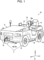
- Cartesian coordinate system S may be used in which X, Y and Z axes indicate the front-rear, the left-right and the up-down directions of the vehicle 10, respectively, when the vehicle 10 is at a stop on a road surface.
- the vehicle 10 is a towing tractor that is used for transport of cargo at an airport.
- the vehicle 10 includes a vehicle body 11 that has at the lower front thereof a pair of front wheels 12 and at the lower rear thereof a pair of rear wheels 13.
- the vehicle 10 is a battery-powered towing tractor having a motor which is driven by electric power from a battery.
- An operator seat 14 is arranged in the rear of the vehicle body 11 of the vehicle 10.
- a steering device 15 is disposed in front of the seat 14.
- the steering device 15 includes a steering wheel 15a that is operated by an operator of the vehicle 10 and a link mechanism (not shown) that is operated in accordance with the operation of the steering wheel 15a.
- the steering device 15 allows the paired front wheels 12 to be steered via the link mechanism in the direction in which the steering wheel 15a is turned by the operator of the vehicle 10.
- An accelerator pedal (not shown) and a brake pedal 16 are disposed in the lower front of the seat 14.
- a master cylinder 17 is disposed frontward of the seat 14 in the vehicle body 11.
- the master cylinder 17 pressurizes brake fluid in accordance with the operation of the brake pedal 16.
- the master cylinder 17 and the brake fluid correspond to the pressure source and the pressure fluid, respectively, according to the present invention.
- Each of the paired front wheels 12 and the paired rear wheels 13 is provided with a brake device in which brake fluid oil serves as the working medium.
- each front wheel 12 is provided with a disk brake device 20.
- Each rear wheel 13 is provided with a disk brake device or a drum brake device.
- a suspension device 18 is disposed in the lower front of the vehicle 10.
- a beam member 19 is suspended from the vehicle body 11 via a spring or a shock absorber (not shown).
- the beam member 19 extends in the vehicle width direction and connects the front wheels 12 which are disposed on the right and the left of the vehicle 10.
- the front wheels 12 are collectively suspended by the beam member 19.
- the beam member 19 extends in the direction of Y-axis.
- a knuckle 30 is provided on each end of the beam member 19 to support the front wheel 12 and the disk brake device 20.
- Numeral 19a designates one end of the beam member 19 that is positioned at the front left of the vehicle 10.
- the disk brake device 20 includes a brake caliper 21 that is fixed to the knuckle 30, a disk rotor 22 that is rotatable with the front wheel 12 and a pair of brake pads (not shown) that are disposed on the opposite sides of the disk rotor 22.
- the brake caliper 21 holds the paired brake pads.
- the brake caliper 21 includes at least one piston (not shown) and an introduction portion 21 a through which brake fluid is introduced from a brake hose 40, which will be described later.
- the piston is actuated by the pressure of brake fluid acting in the brake caliper 21 thereby to press the brake pads against the disk rotor 22.
- the disk rotor 22 is disposed coaxially and rotatable with the front wheel 12. Pressure from the piston of the brake caliper 21 causes the brake pads to hold therebetween the disk rotor 22. Because the brake caliper 21 is fixed to the knuckle 30, the brake caliper 21 and the brake pads are not rotatable. Therefore, the rotation speed of the front wheel 12 is reduced with a reduction of the rotation speed of the disk rotor 22.
- the knuckle 30 supports the front wheel 12 rotatably about its axis. In addition, the front wheel 12 is steerably supported by the knuckle 30.
- the knuckle 30 has a pin hole 30h in which a kingpin 31 is fixedly inserted to rotate with the knuckle 30.
- the kingpin 31 is formed by a columnar metal and is press fitted in the pin hole 30h having a circular shape in cross-section.
- the kingpin 31 is disposed coaxially with the pin hole 30h.
- the kingpin 31 is supported at the upper end thereof by a roller bearing 31 a in the upper portion 19b of the beam member 19 and at the lower end thereof by a roller bearing 31 b in the lower portion 19c of the beam member 19.
- a thrust bearing 31 c is mounted on the kingpin 31 immediately below the roller bearing 31 a so as to support the upward load from the front wheel 12.
- the knuckle 30 and the kingpin 31 are integrally rotatable about the kingpin axis KP.
- the kingpin 31 is supported by the upper portion 19b and the lower portion 19c of the beam member 19 so that the kingpin axis KP extends in the vertical direction (Z-axis direction) of the vehicle 10.
- the knuckle 30 has an arm 32 extending in the direction that crosses the axis of the front wheel 12 and also the extending direction of the pin hole 30h.
- the arm 32 extends in the radial direction of the kingpin 31.
- the aforementioned link mechanism of the steering wheel 15a is mounted to the arm 32.
- the arm 32 is moved by the link mechanism that is allowed to move in the longitudinal direction of the beam member 19 in response to the operation of the steering wheel 15a, which causes the knuckle 30 to be turned about the kingpin axis KP.
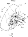
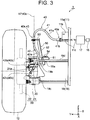
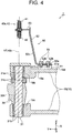
- FIGS. 2 , 3 , 4 , 7 and 8 the brake hose support structure 1 disposed adjacent to the front wheel 12 on the left side of the vehicle 10 is illustrated.
- the brake hose support structure 1 for the front wheel 12 on the left side of the vehicle 10
- the front wheel 12 on the right side of the vehicle 10 uses a substantially the same brake hose support structure 1.
- the brake hose support structure 1 includes the brake hose 40 through which brake fluid is flowed between the master cylinder 17 of the vehicle 10 and the brake caliper 21 of the disk brake device 20, and a hose support 50 that supports the brake hose 40.
- the brake hose 40 includes a first hose 41 that is disposed adjacent to the master cylinder 17 and has a first end 40a of the brake hose 40, a second hose 42 that is disposed adjacent to the brake caliper 21 and has a second end 40b of the brake hose 40, and a connecting member 43 (supporting portion 40s).
- the brake hose 40 has the first end 40a that is located adjacent to the master cylinder 17, the second end 40b that is located adjacent to the brake caliper 21, and the supporting portion 40s that is disposed between the first and second ends 40a, 40b.
- the first hose 41 includes a rubber hose 41a and a cylindrical fitting 41 b.
- the rubber hose 41 a connects a pipe 11 c, which is connected to the master cylinder 17 in the vehicle body 11, with the connecting member 43.
- the fitting 41 b fixes the rubber hose 41 a at the first end 40a of the brake hose 40.
- the fitting 41 b is fastened with the rubber hose 41 a inserted so that the rubber hose 41 a is fluid-tightly fixed.
- the fitting 41 b is supported at the first end 40a of the brake hose 40 by a support member 11 b.
- the support member 11 b has a plate shape and extends in Y-axis direction from the frame 11 a of the vehicle body 11.
- the pipe 11c is inserted through a hole (not shown) formed through the frame 11 a and extends out from the vehicle body 11.
- the second hose 42 includes a rubber hose 42a that connects the connecting member 43 with the brake caliper 21 and a cylindrical fitting 42b that fixes the rubber hose 42a at the second end 40b of the brake hose 40.
- the fitting 42b is fastened with the rubber hose 42a inserted so that the rubber hose 42a is fluid-tightly fixed.
- the fitting 42b is formed on the side thereof opposite from the rubber hose 42a with a banjo portion 42c.
- the fitting 42b and the banjo portion 42c correspond to the second end 40b of the brake hose 40 according to the present invention.
- the banjo portion 42c is connected to the introduction portion 21a of the brake caliper 21 and fixed to the brake caliper 21 by a banjo bolt (not shown).
- a banjo bolt (not shown).
- the connecting member 43 has a generally cylindrical shape and is made of a metal.
- the connecting member 43 includes a body portion 43a and fixing portions 43b, 43c disposed along the axial direction of the connecting member 43.
- the body portion 43a of the connecting member 43 is supported by the hose support 50.
- the body portion 43a has a generally cylindrical shape and forms the center portion of the connecting member 43.
- the body portion 43a has a circular hole 43h extending in the axial direction of the body portion 43a.
- the hole 43h provides a fluid communication between the rubber hoses 41 a, 42a of the first and second hoses 41, 42, respectively.
- the fixing portions 43b, 43c have a cylindrical shape and form the end portions on the opposite sides of the body portion 43a.
- the fixing portions 43b, 43c and the body portion 43a are formed coaxially.
- the fixing portion 43b is fixed fluid-tight on the rubber hose 41 a of the first hose 41.
- the fixing portion 43c is fixed fluid-tight on the rubber hose 42a of the second hose 42.
- the brake hose 40 is formed into a single hose by connecting the first and second hoses 41, 42 at the connecting member 43.
- the axis 40c of the brake hose 40 at the connecting member 43 coincides with the axis of the connecting member 43. In other words, the position of the connecting member 43 determines the orientation of the brake hose 40 at the connecting member 43.
- the body portion 43a of the connecting member 43 has at the outer periphery thereof a pair of flat surfaces 43s extending parallel to the axis 40c of the brake hose 40.
- the cross-sectional shape of the part of the body portion 43a corresponding to the paired flat surfaces 43s which is taken across the axis 40c is substantially the same as that of a hole 53h of a hose support portion 53, which will be described later.
- the body portion 43a has in the outer periphery thereof a groove 43d formed at a position adjacent to the fixing portion 43b, extending over the entire circumference of the body portion 43a around the axis of the hole 43h.
- a fixing ring 44 which is formed by an E-ring or a C-ring, is fitted into the groove 43d.
- the body portion 43a further has at the outer periphery thereof a groove 43e disposed adjacent to the fixing portion 43c, extending over the entire circumference of the body portion 43a around the axis of the hole 43h.
- a fixing plate 45 having a curved surface along the fitting direction, which plate will be described later, is fitted in the groove 43d.
- the hose support 50 that supports the brake hose 40 at the connecting member 43 between the first and second ends 40a, 40b with reference to FIGS. 3 to 6 .
- the hose support 50 includes a base 51, a body 52 and the hose support portion 53.
- the base 51 of the hose support 50 is mounted to the upper surface 19d of the beam member 19 at a position that is adjacent to the one end 19a of the beam member 19.
- the base 51 is formed by a metal plate and has a hut shape in cross section, as shown in FIGS. 3 and 4 .
- the base 51 has a flat upper surface 51 a extending perpendicularly to the kingpin axis KP.
- the base 51 has a thickness between 10 mm and 20 mm. Any suitable shape of any suitable material may be used for the base 51.
- the base 51 of the hose support 50 is fixed to the upper surface 19d of the beam member 19 by soldering with the upper surface 51a of the base 51 facing upward.
- the upper surface 51 a of the base 51 extends generally parallel to the upper surface 19d of the beam member 19.
- Two female threaded holes 51 h are formed through the base 51 and are engaged with bolts 54.
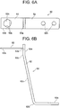
- the body 52 of the hose support 50 is formed by bending a metal plate at bent portions 52b, 52d and includes a fixing portion 52a, a stand portion 52c and an upper end portion 52e.
- the body 52 is made of a steel and has a thickness between 4 mm and 6 mm.
- the body 52 need not necessarily be formed by a metal plate member, but any suitable shape such as a bar, a pipe, a square member of any suitable material may be used for the body 52 of the hose support 50.
- the fixing portion 52a is fixed to the upper surface 51 a of the base 51.
- the fixing portion 52a has a substantially the same shape, for example a rectangular shape, as the upper surface 51 a of the base 51 in plan view.
- the fixing portion 52a has therethrough two holes 52h and is fixed to the base 51 with the bolts 54 that are inserted through the holes 52h and screwed in the threaded holes 51 h. It is to be noted that any number of holes such as 52h may be formed through the fixing portion 52a.
- the stand portion 52c extends upwardly from the fixing portion 52a with such an inclination that the spaced distance from the stand portion 52c to the kingpin axis KP is decreased toward the upper end of the stand portion 52c.
- the upper end portion 52e With the body 52 of the hose support 50 fixed to the beam member 19 by way of the base 51, the upper end portion 52e extends upward from the bent portion 52d perpendicularly to the fixing portion 52a, as shown in FIGS. 4 and 6B .
- the upper end portion 52e extends in vertical Z-axis direction that is generally parallel to the kingpin axis KP.
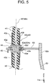
- the hose support portion 53 is configured to support the connecting member 43 of the brake hose 40.
- the hose support portion 53 has a rectangular plate shape having a width that is substantially the same as the body 52 of the hose support 50.
- the hose support portion 53 has a proximal end 53a that is fixed to the upper end portion 52e of the body 52 by soldering or any suitable method.
- the hose support portion 53 may be fastened to the body 52 by a bolt.
- the hose support portion 53 extends in a direction that is generally perpendicular to the upper end portion 52e and to the kingpin axis KP. Specifically, the hose support portion 53 extends generally parallel to the fixing portion 52a of the body 52, or to the upper surface 51 a of the base 51. Thus, the hose support portion 53 extends generally perpendicularly to the kingpin axis KP.
- the hose support portion 53 of the hose support 50 includes a distal end 53b having the hole 53h through which the connecting member 43 of the brake hose 40 is inserted.
- the axis of the hole 53h coincides with the kingpin axis KP.
- a pair of flat surfaces 53s are formed in the inner surface of the hole 53h.
- the part of the body portion 43a of the connecting member 43 corresponding to the flat surfaces 53s of the hole 53h has a shape substantially the same as the hole 53h of the hose support portion 53 in cross section perpendicular to the axis of the connecting member 43.
- the flat surfaces 53s are formed at positions corresponding to the flat surfaces 43s of the body portion 43a of the connecting member 43, and the body portion 43a of the connecting member 43 is inserted through the hole 53h of the hose support portion 53.
- the paired flat surfaces 53s of the hose support portion 53 are formed extending parallel to each other and the same is true for paired flat surfaces 43s of the connecting member 43. Because the flat surfaces 53s of the hose support portion 53 are set in contact when the body portion 43a of the connecting member 43 is inserted through the hole 53h, the rotation of the body portion 43a about the axis 40c of the brake hose 40 is prevented.
- the flat surfaces 53s of the hose support portion 53 and the flat surfaces 43s of the connecting member 43 cooperate to fix the body portion 43a relative to the axis 40c of the brake hose 40 and prevent the rotation of the body portion 43a.
- the body portion 43a of the connecting member 43 is fixed at a position where twisting force applied to the brake hose 40 is minimized. More specifically, the paired flat surfaces 53s are formed at such positions in the hole 53h of the hose support portion 53 that the twisting force applied to the second hose 42 is minimized when the second end 40b of the brake hose 40 is positioned at the middle point M.
- the thickness of the hose support portion 53 is substantially the same as the spaced distance between the groove 43d and the groove 43e, about 2 mm and 3 mm.
- the hose support portion 53 is formed by a steel plate. Any shape (e.g. bar, pipe and square column) of any material may be used for the hose support portion 53 as long as it can support the connecting member 43 of the brake hose 40.
- the position of the hose support portion 53 where the connecting member 43 is supported by the hose support portion 53 in the vertical direction, or Z-axis direction, is determined depending on the spaced distance between the connecting member 43 and the second end 40b of the brake hose 40, which spaced distance corresponds to the dimension from an imaginary plane extending perpendicularly to the kingpin axis KP at the second end 40b to the connecting member 43.
- Such dimension is set based on the allowable bending deformation of the second hose 42 which is determined by the durability of the second hose 42.
- the allowable bending deformation may be calculated using simulations.
- the brake hose 40 is supported by the hose support 50 at the connecting member 43.
- the connecting member 43 corresponds to the supporting portion 40s of the brake hose 40.
- the fixing ring 44 and the fixing plate 45 are fitted into the groove 43d and the groove 43e in the upper part and lower part of the hose support portion 53, respectively, with the connecting member 43 inserted through the hole 53h of the hose support portion 53.
- the hose support portion 53 is held between the fixing ring 44 and the fixing plate 45, so that the movement of the body portion 43a of the connecting member 43 in the axial direction of the hole 43h is prevented thereby to position the body portion 43a at the hose support portion 53.
- the paired flat surfaces 53s formed in the inner periphery of the hole 53h prevents the rotation of the connecting member 43 about the axis of the hole 43h thereof, or the axis 40c of the brake hose 40. Accordingly, the connecting member 43 is fixed to the hose support portion 53.
- the axis 40c of the brake hose 40 at the connecting member 43 extends perpendicular to the upper surface 19d of the beam member 19 at one end 19a thereof.
- the hose support 50 supports the brake hose 40 such that the axis 40c of the brake hose 40 extends parallel to the kingpin axis KP.
- the axis 40c of the brake hose 40 at the connecting member 43 coincides with the kingpin axis KP.
- the knuckle 30 and kingpin 31 are integrally rotatable about the kingpin axis KP.
- the brake caliper 21 fixed to the knuckle 30 and the second end 40b of the brake hose 40 fixed to the introduction portion 21 a of the brake caliper 21 are rotated integrally about the kingpin axis KP.
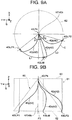
- FIGS. 9A and 9B there is shown an imaginary cone 60 which illustrates the movement of the second end 40b of the brake hose 40.
- the imaginary cone 60 has an apex at the point P4 and a circular bottom plane 62 extending parallel to the flat surface XY.
- the point P3 indicates the center of the bottom plane 62.
- the point P4 corresponds to the position of the connecting member 43.
- the circumference of the bottom plane 62 corresponds to the circumference of a circle having its center at the kingpin axis KP and a radius corresponding the distance from the axis KP to the second end 40b of the brake hose 40.
- An imaginary line passing through the point P4 and expending perpendicular to the bottom plane 62 coincides with the axis 40c of the brake hose 40 at the connecting member 43.
- the second end 40b of the brake hose 40 is movable along the arc C of the circumference of the bottom plane 62.
- the second end 40b of the brake hose 40 is movable along the arc C having a center of curvature at the kingpin axis KP.
- P1 and P2 indicates first and second points which correspond to the opposite ends of the arc C in the imaginary cone 60.
- the first and second points P1, P2 correspond to the positions of the second end 40b when the front wheel 12 is turned to its steering limit positions in clockwise and counterclockwise directions as seen from the top, respectively.
- the middle point M on the arc C corresponds to the position where the distances from the first point P1 and the second point P2 to the middle point M are substantially the same.
- the curved line 42x indicates the position of the second hose 42 when the second end 40b is located at the middle point M.
- the curved lines 42y, 42z indicate the positions of the second hose 42 when the second end 40b is located at the first and second points P1, P2, respectively.
- the position of the second hose 42 is moved from the curved line 42x to the curved line 42y or 42z, respectively.
- the curved lines 42y, 42z have a substantially the same shape as the curved line 42x.
- the second end 40b of the brake hose 40 is movable within the arc C of the circumference of the bottom plane 62. Because the axis 40c of the brake hose 40 at the connecting member 43 coincides with the kingpin axis KP, the position of the second end 40b of the brake hose 40 is not greatly displaced relative to the imaginary line extending through the point P4 and perpendicularly to the bottom plane 62 regardless of the movement of the second end 40b along the arc C.
- the position of the second end 40b of the brake hose 40 is not greatly displaced relative to the axis 40c of the brake hose 40 at the connecting member 43 by the movement of the second end 40b around the kingpin axis KP with the steering movement of the front wheel 12.
- the axis 40c of the brake hose 40 at the connecting member 43 extends across the kingpin axis KP as in the case of the prior art, localized bending may occur in the second hose 42 at the connecting member 43 when the front wheel 12 is steered.
- the above-described positional relationship between the axis 40c of the brake hose 40 at the connecting member 43 and the second end 40b of the brake hose 40 restricts the localized bending of the second hose 42 of the brake hose 40 which may occur with the steering of the front wheel 12.
- the above-described brake hose support structure 1 prevents the displacement of the second end 40b relative to the axis 40c of the brake hose 40 at the connecting member 43 when the second end 40b of the brake hose 40 is moved about the kingpin axis KP with the steering movement of the front wheel 12.
- the bending deformation of the brake hose 40 with the steering movement of the front wheel 12 may be prevented.
- the axis 40c of the brake hose 40 coincides with the kingpin axis KP.
- the line which corresponds to the axis of the brake hose 40 and also to the kingpin axis KP extends from the point P4 which corresponds to the connecting member 43 perpendicularly to the point P3 at the center of the bottom plane 62.
- the imaginary cone 60 has a right circular cone shape.
- the angular position of the second end 40b of the brake hose 40 relative to the perpendicular line, or the axis of the brake hose 40 hardly changes irrespective of the movement of the second end 40b of the brake hose 40 along the arc C in the imaginary cone 60. Accordingly, the angular position of the second end 40b at the connecting member 43 (supporting portion 40s) relative to the axis 40c hardly changes when the second end 40b of the brake hose 40 is turned about the kingpin axis KP with the steering movement of the front wheel 12. Comparing bending of the brake hose 40 at various steering angles, the difference in the degree of bending of the brake hose 40 caused by the steering movement of the front wheel 12 may be restricted to a small extent.
- the axis 40c of the brake hose 40 at the connecting member 43 need not necessarily coincide with the kingpin axis KP, as long as the supporting portion 40s, or the connecting member 43, of the brake hose 40 is supported by the hose support 50 such that the axis 40c of the brake hose 40 extends parallel to the kingpin axis KP.
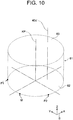
- the axis of the brake hose 40 at the connecting member 43 may be set at 40c' extending parallel to the kingpin axis KP passing through an imaginary circular column 61, as shown in FIG. 10 .
- the imaginary circular column 61 has an upper plane 63 that has substantially the same shape as and coaxially with the bottom plane 62 of the imaginary cone 60.
- the position of the second end 40b of the brake hose 40 relative to the axis 40c' is not greatly displaced regardless of the movement of the second end 40b along the arc C of the imaginary circular column 61.
- the position of the second end 40b relative to the axis 40c' of the brake hose 40 at the connecting member 43 is not greatly displaced, with the result that bending of the brake hose 40 with the steering movement of the front wheel 12 may be prevented.
- the set position of the second end 40b is set at the middle point M between the first and second points P1, P2 in the imaginary cone 60.
- the set position of the second end 40b is located at a position along the arc C at which the second end 40b of the brake hose 40 is mounted to the introduction portion 21 a of the brake caliper 21.
- the second end 40b of the brake hose 40 is mounted to the introduction portion 21 a of the brake caliper 21 so that the distance L1 from the first point P1 to the set position is substantially the same as the distance L2 from the second point P2 to the set position.
- the central angle ⁇ 1 which is formed by the movement of the second end 40b from the set position to the first point P1 along the arc C, is substantially the same as the central angle ⁇ 2, which is formed by the movement of the second end 40b from the set position to the second point P2. If the set position for the second end 40b is offset from the middle point M, one of the central angles ⁇ 1, ⁇ 2 becomes greater than the other. By setting the set position of the second end 40b at the middle point M between the first and second points P1, P2 along the arc C, twisting of the second hose 42 is reduced, as a result of which the serviceable life of the brake hose 40 may be increased.
- the angular position of the body portion 43a with respect to the axis 40c when the body portion 43a is inserted through the hole 53h of the hose support portion 53 and fixed is set so that twisting force applied to the second hose 42 is minimized when the second end 40b of the brake hose 40 is located at the middle point M, with the result that the deformation caused by twisting may be reduced.
- the steering limit angle of the front wheel 12 in one direction differs from that in the other direction as shown in FIGS. 7 and 8 . In this case, the position of the second end 40b when the front wheel 12 is positioned for straight-forward movement do not coincide with the middle point M.
- the present invention is not limited to the above-described embodiment, but it may be modified in various manners within the scope of the present invention.
- the brake hose support structure 1 of the present invention is applicable to any other vehicles than the towing tractor.
- the brake hose 40 may be supported rotatably about the axis 40c of the brake hose 40 at the connecting member 43, or at the supporting portion 40s of the brake hose 40.
- the hole 53h of the hose support portion 53 may have a circular shape in cross section so as not to restrict the rotation of the body portion 43a of the connecting member 43 at the hole 43h.
- the supporting portion 40s of the brake hose 40 may be supported rotatably about the axis 40c through a bearing. In this case, twisting of the brake hose 40 occurs between the first end 40a and the second end 40b with the steering movement of the front wheel 12.
- the brake hose 40 which is formed by the first and second hoses 41, 42 connected by the connecting member 43, may be replaced with a brake hose formed by a single rubber hose. In this case, the brake hose is supported by the hose support 50 without the connecting member 43.
- any other part of the brake hose 40 other than that corresponding to the connecting member 43 may be used as the position at which the brake hose 40 is supported.
- the hose support 50 may have any suitable configuration as long as it supports the brake hose 40 with the axis 40c thereof extending parallel to the kingpin axis KP.
- the kingpin axis KP need not necessarily extend in the X-axis direction.
- the kingpin axis KP may be inclined with respect to the Z-axis direction in a plane extending parallel to the plane ZX.
- the connecting member 43 is supported by the hose support 50 in a position inclined in the direction in which the kingpin axis KP is inclined, so that the brake hose 40 is disposed with axis 40c thereof extending parallel to the kingpin axis KP at the connecting member 43. Because the brake hose 40 is supported by the hose support 50 in a such position that the axis 40c of the brake hose 40 extends parallel to the kingpin axis KP, the above-described effects described with reference to the embodiment may be achieved.
- the brake hose support structure 1 is applicable to the rear wheel 13 of the vehicle 10 if it is configured to be steerable with the operation of the steering device 15 and provided with the disk brake device 20.
Landscapes
- Engineering & Computer Science (AREA)
- Mechanical Engineering (AREA)
- Transportation (AREA)
- General Engineering & Computer Science (AREA)
- Chemical & Material Sciences (AREA)
- Combustion & Propulsion (AREA)
- Valves And Accessory Devices For Braking Systems (AREA)
- Braking Arrangements (AREA)
- Supports For Pipes And Cables (AREA)
Applications Claiming Priority (1)
| Application Number | Priority Date | Filing Date | Title |
|---|---|---|---|
| JP2016087085A JP6418198B2 (ja) | 2016-04-25 | 2016-04-25 | 車両のブレーキホースの支持構造 |
Publications (2)
| Publication Number | Publication Date |
|---|---|
| EP3246220A1 true EP3246220A1 (fr) | 2017-11-22 |
| EP3246220B1 EP3246220B1 (fr) | 2020-12-23 |
Family
ID=58530436
Family Applications (1)
| Application Number | Title | Priority Date | Filing Date |
|---|---|---|---|
| EP17165701.8A Active EP3246220B1 (fr) | 2016-04-25 | 2017-04-10 | Structure de support de tuyau de frein de véhicule |
Country Status (7)
| Country | Link |
|---|---|
| US (1) | US10118601B2 (fr) |
| EP (1) | EP3246220B1 (fr) |
| JP (1) | JP6418198B2 (fr) |
| KR (1) | KR102006534B1 (fr) |
| CN (1) | CN107444383B (fr) |
| AU (1) | AU2017202170B2 (fr) |
| TW (1) | TWI668143B (fr) |
Cited By (1)
| Publication number | Priority date | Publication date | Assignee | Title |
|---|---|---|---|---|
| FR3144641A1 (fr) * | 2023-01-04 | 2024-07-05 | Psa Automobiles Sa | Moyen de fixation d’un tuyau flexible pour véhicule automobile |
Families Citing this family (7)
| Publication number | Priority date | Publication date | Assignee | Title |
|---|---|---|---|---|
| US10591003B2 (en) * | 2017-06-16 | 2020-03-17 | Polaris Industries Inc. | Brake assembly shield and scraper |
| NL2019535B1 (en) * | 2017-09-13 | 2019-03-27 | Walraven Holding Bv J Van | Pipe support structure |
| JP7174349B2 (ja) * | 2018-10-25 | 2022-11-17 | いすゞ自動車株式会社 | 車両の配管ホースの支持構造 |
| JP7404611B2 (ja) * | 2019-12-19 | 2023-12-26 | メルセデス・ベンツ グループ アクチェンゲゼルシャフト | 車両用制動装置 |
| KR102296534B1 (ko) * | 2020-01-13 | 2021-09-02 | 주식회사 화승알앤에이 | 브레이크 호스의 레이아웃 설정용 금구 |
| KR102296535B1 (ko) * | 2020-01-13 | 2021-09-02 | 주식회사 화승알앤에이 | 브레이크 호스의 레이아웃 설정용 금구 |
| CN111824099B (zh) * | 2020-08-18 | 2025-06-27 | 杭叉集团股份有限公司 | 一种转向轮制动机构及具有该机构的三支点工程车 |
Citations (4)
| Publication number | Priority date | Publication date | Assignee | Title |
|---|---|---|---|---|
| WO1995012074A1 (fr) * | 1993-10-28 | 1995-05-04 | Earl's Supply Company | Systeme de tuyau souple de freins de vehicules avec amortisseur de vibrations |
| EP1514790A2 (fr) * | 2003-09-09 | 2005-03-16 | HONDA MOTOR CO., Ltd. | Support de conduit flexible de frein |
| JP2006069437A (ja) | 2004-09-03 | 2006-03-16 | Honda Motor Co Ltd | 鞍乗り型不整地走行車両のブレーキホース支持構造 |
| US20150210234A1 (en) * | 2014-01-30 | 2015-07-30 | Honda Motor Co., Ltd. | Suspension structure for irregular ground traveling vehicle |
Family Cites Families (18)
| Publication number | Priority date | Publication date | Assignee | Title |
|---|---|---|---|---|
| US3851672A (en) * | 1973-05-18 | 1974-12-03 | Gen Motors Corp | Hose assembly with prepositioned hose mounting bracket |
| JPS54139430A (en) | 1978-04-21 | 1979-10-29 | Hitachi Ltd | Crt display unit |
| DE3004421C2 (de) * | 1980-02-07 | 1981-11-26 | Adam Opel AG, 6090 Rüsselsheim | Befestigungsvorrichtung für einen Bremsschlauch |
| JPS5780961A (en) * | 1980-11-10 | 1982-05-20 | Nissan Motor Co Ltd | Piping structure for brake hose |
| JPS57209456A (en) * | 1981-06-18 | 1982-12-22 | Nissan Motor Co Ltd | Front brake tube retaining construction for automobile |
| JPS6036965B2 (ja) * | 1981-07-30 | 1985-08-23 | 日産自動車株式会社 | 操向車輪の懸架装置 |
| JP2825185B2 (ja) | 1990-06-19 | 1998-11-18 | 黒田精工株式会社 | メタルシール弁及びその製造方法 |
| KR19990015464U (ko) | 1997-10-16 | 1999-05-15 | 추호석 | 차량의 브레이크 호스 장착용 커넥터 |
| JP2000108885A (ja) * | 1998-10-08 | 2000-04-18 | Fuji Heavy Ind Ltd | 車両用ブレーキホース保持構造 |
| DE19944600A1 (de) * | 1999-09-16 | 2001-04-05 | Fte Automotive Gmbh | Halterung für eine Druckleitung |
| JP3742030B2 (ja) | 2002-04-23 | 2006-02-01 | 富士通株式会社 | 平面光導波回路デバイスの製造方法 |
| US6830075B1 (en) * | 2003-05-09 | 2004-12-14 | Dana Corporation | Hose assembly with integrally molded brake hose bracket |
| US7451857B2 (en) | 2004-09-03 | 2008-11-18 | Honda Motor Co., Ltd. | Seat mount structure for saddle ride type vehicle |
| US7380830B2 (en) * | 2005-02-03 | 2008-06-03 | Honda Motor Co., Ltd. | Vehicle front body structure |
| JP2010052536A (ja) * | 2008-08-27 | 2010-03-11 | Nissan Diesel Motor Co Ltd | 車両のブレーキ装置 |
| CN202686352U (zh) * | 2012-06-28 | 2013-01-23 | 南京依维柯汽车有限公司 | 一种前轮边制动管路装置 |
| US8899533B2 (en) * | 2013-01-16 | 2014-12-02 | Honda Motor Co., Ltd. | Vehicle hydraulic brake hose assembly |
| US9902388B2 (en) * | 2015-01-20 | 2018-02-27 | Toyota Motor Engineering & Manufacturing North America, Inc. | Brake hose prototype assembly and method for prototyping a brake hose assembly |
-
2016
- 2016-04-25 JP JP2016087085A patent/JP6418198B2/ja active Active
-
2017
- 2017-04-03 AU AU2017202170A patent/AU2017202170B2/en active Active
- 2017-04-10 EP EP17165701.8A patent/EP3246220B1/fr active Active
- 2017-04-14 US US15/487,899 patent/US10118601B2/en active Active
- 2017-04-21 KR KR1020170051517A patent/KR102006534B1/ko active Active
- 2017-04-24 CN CN201710270353.7A patent/CN107444383B/zh active Active
- 2017-04-24 TW TW106113565A patent/TWI668143B/zh active
Patent Citations (4)
| Publication number | Priority date | Publication date | Assignee | Title |
|---|---|---|---|---|
| WO1995012074A1 (fr) * | 1993-10-28 | 1995-05-04 | Earl's Supply Company | Systeme de tuyau souple de freins de vehicules avec amortisseur de vibrations |
| EP1514790A2 (fr) * | 2003-09-09 | 2005-03-16 | HONDA MOTOR CO., Ltd. | Support de conduit flexible de frein |
| JP2006069437A (ja) | 2004-09-03 | 2006-03-16 | Honda Motor Co Ltd | 鞍乗り型不整地走行車両のブレーキホース支持構造 |
| US20150210234A1 (en) * | 2014-01-30 | 2015-07-30 | Honda Motor Co., Ltd. | Suspension structure for irregular ground traveling vehicle |
Cited By (1)
| Publication number | Priority date | Publication date | Assignee | Title |
|---|---|---|---|---|
| FR3144641A1 (fr) * | 2023-01-04 | 2024-07-05 | Psa Automobiles Sa | Moyen de fixation d’un tuyau flexible pour véhicule automobile |
Also Published As
| Publication number | Publication date |
|---|---|
| AU2017202170A1 (en) | 2017-11-09 |
| AU2017202170B2 (en) | 2018-10-25 |
| CN107444383A (zh) | 2017-12-08 |
| KR102006534B1 (ko) | 2019-08-01 |
| CN107444383B (zh) | 2019-12-27 |
| KR20170121710A (ko) | 2017-11-02 |
| JP6418198B2 (ja) | 2018-11-07 |
| TWI668143B (zh) | 2019-08-11 |
| JP2017196930A (ja) | 2017-11-02 |
| US20170305401A1 (en) | 2017-10-26 |
| EP3246220B1 (fr) | 2020-12-23 |
| US10118601B2 (en) | 2018-11-06 |
| TW201741172A (zh) | 2017-12-01 |
Similar Documents
| Publication | Publication Date | Title |
|---|---|---|
| EP3246220B1 (fr) | Structure de support de tuyau de frein de véhicule | |
| RU2517274C2 (ru) | Независимая подвеска транспортного средства | |
| US8240687B2 (en) | Wheel suspension system for a steerable wheel | |
| US20100102527A1 (en) | Suspension device | |
| CN111226050A (zh) | 万向接头、伸缩连杆以及悬架 | |
| EP2524824B1 (fr) | Structure de suspension et procédé de fabrication d'un lien de suspension | |
| CN110234522A (zh) | 车辆悬架系统 | |
| JPH10109510A (ja) | フロントサスペンション装置 | |
| US20120056396A1 (en) | Wheel suspension for a motor vehicle | |
| US20180178607A1 (en) | Joint connection and arrangement for mounting a wheel | |
| EP4140786B1 (fr) | Véhicule de travail | |
| JP2000006624A (ja) | 産業車両の車体フレーム及び産業車両 | |
| US20220194466A1 (en) | Steering pin and knuckle assembly | |
| EP1957343B1 (fr) | Ensemble de direction pour un véhicule automobile | |
| US6719311B2 (en) | Vehicle steering assembly | |
| JP2000033809A (ja) | 独立懸架装置 | |
| EP0842080B1 (fr) | Butee de braquage pour vehicules | |
| JP6904647B2 (ja) | 作業車両の操舵装置および作業車両 | |
| EP4603308A1 (fr) | Véhicule de travail comprenant un capteur pour détecter le mouvement d'un essieu réglable en hauteur | |
| JP6764656B2 (ja) | 作業機のサスペンション装置 | |
| JP2007055360A (ja) | 車両用ステアリング装置 | |
| JP2017178249A (ja) | トーションビーム式サスペンション | |
| JPH02227374A (ja) | 車両の後輪操舵装置 | |
| JP2016175454A (ja) | ハイマウントダブルウィッシュボーン式サスペンション用ナックル |
Legal Events
| Date | Code | Title | Description |
|---|---|---|---|
| PUAI | Public reference made under article 153(3) epc to a published international application that has entered the european phase |
Free format text: ORIGINAL CODE: 0009012 |
|
| STAA | Information on the status of an ep patent application or granted ep patent |
Free format text: STATUS: REQUEST FOR EXAMINATION WAS MADE |
|
| 17P | Request for examination filed |
Effective date: 20170410 |
|
| AK | Designated contracting states |
Kind code of ref document: A1 Designated state(s): AL AT BE BG CH CY CZ DE DK EE ES FI FR GB GR HR HU IE IS IT LI LT LU LV MC MK MT NL NO PL PT RO RS SE SI SK SM TR |
|
| AX | Request for extension of the european patent |
Extension state: BA ME |
|
| GRAP | Despatch of communication of intention to grant a patent |
Free format text: ORIGINAL CODE: EPIDOSNIGR1 |
|
| STAA | Information on the status of an ep patent application or granted ep patent |
Free format text: STATUS: GRANT OF PATENT IS INTENDED |
|
| RIC1 | Information provided on ipc code assigned before grant |
Ipc: B60T 17/04 20060101AFI20200701BHEP |
|
| INTG | Intention to grant announced |
Effective date: 20200724 |
|
| INTG | Intention to grant announced |
Effective date: 20200731 |
|
| GRAS | Grant fee paid |
Free format text: ORIGINAL CODE: EPIDOSNIGR3 |
|
| GRAA | (expected) grant |
Free format text: ORIGINAL CODE: 0009210 |
|
| STAA | Information on the status of an ep patent application or granted ep patent |
Free format text: STATUS: THE PATENT HAS BEEN GRANTED |
|
| AK | Designated contracting states |
Kind code of ref document: B1 Designated state(s): AL AT BE BG CH CY CZ DE DK EE ES FI FR GB GR HR HU IE IS IT LI LT LU LV MC MK MT NL NO PL PT RO RS SE SI SK SM TR |
|
| REG | Reference to a national code |
Ref country code: GB Ref legal event code: FG4D |
|
| REG | Reference to a national code |
Ref country code: DE Ref legal event code: R096 Ref document number: 602017029872 Country of ref document: DE |
|
| REG | Reference to a national code |
Ref country code: AT Ref legal event code: REF Ref document number: 1347429 Country of ref document: AT Kind code of ref document: T Effective date: 20210115 |
|
| REG | Reference to a national code |
Ref country code: IE Ref legal event code: FG4D |
|
| PG25 | Lapsed in a contracting state [announced via postgrant information from national office to epo] |
Ref country code: NO Free format text: LAPSE BECAUSE OF FAILURE TO SUBMIT A TRANSLATION OF THE DESCRIPTION OR TO PAY THE FEE WITHIN THE PRESCRIBED TIME-LIMIT Effective date: 20210323 Ref country code: RS Free format text: LAPSE BECAUSE OF FAILURE TO SUBMIT A TRANSLATION OF THE DESCRIPTION OR TO PAY THE FEE WITHIN THE PRESCRIBED TIME-LIMIT Effective date: 20201223 Ref country code: FI Free format text: LAPSE BECAUSE OF FAILURE TO SUBMIT A TRANSLATION OF THE DESCRIPTION OR TO PAY THE FEE WITHIN THE PRESCRIBED TIME-LIMIT Effective date: 20201223 Ref country code: GR Free format text: LAPSE BECAUSE OF FAILURE TO SUBMIT A TRANSLATION OF THE DESCRIPTION OR TO PAY THE FEE WITHIN THE PRESCRIBED TIME-LIMIT Effective date: 20210324 |
|
| REG | Reference to a national code |
Ref country code: AT Ref legal event code: MK05 Ref document number: 1347429 Country of ref document: AT Kind code of ref document: T Effective date: 20201223 |
|
| REG | Reference to a national code |
Ref country code: NL Ref legal event code: MP Effective date: 20201223 |
|
| PG25 | Lapsed in a contracting state [announced via postgrant information from national office to epo] |
Ref country code: LV Free format text: LAPSE BECAUSE OF FAILURE TO SUBMIT A TRANSLATION OF THE DESCRIPTION OR TO PAY THE FEE WITHIN THE PRESCRIBED TIME-LIMIT Effective date: 20201223 Ref country code: BG Free format text: LAPSE BECAUSE OF FAILURE TO SUBMIT A TRANSLATION OF THE DESCRIPTION OR TO PAY THE FEE WITHIN THE PRESCRIBED TIME-LIMIT Effective date: 20210323 Ref country code: SE Free format text: LAPSE BECAUSE OF FAILURE TO SUBMIT A TRANSLATION OF THE DESCRIPTION OR TO PAY THE FEE WITHIN THE PRESCRIBED TIME-LIMIT Effective date: 20201223 |
|
| PG25 | Lapsed in a contracting state [announced via postgrant information from national office to epo] |
Ref country code: NL Free format text: LAPSE BECAUSE OF FAILURE TO SUBMIT A TRANSLATION OF THE DESCRIPTION OR TO PAY THE FEE WITHIN THE PRESCRIBED TIME-LIMIT Effective date: 20201223 Ref country code: HR Free format text: LAPSE BECAUSE OF FAILURE TO SUBMIT A TRANSLATION OF THE DESCRIPTION OR TO PAY THE FEE WITHIN THE PRESCRIBED TIME-LIMIT Effective date: 20201223 |
|
| REG | Reference to a national code |
Ref country code: LT Ref legal event code: MG9D |
|
| PG25 | Lapsed in a contracting state [announced via postgrant information from national office to epo] |
Ref country code: RO Free format text: LAPSE BECAUSE OF FAILURE TO SUBMIT A TRANSLATION OF THE DESCRIPTION OR TO PAY THE FEE WITHIN THE PRESCRIBED TIME-LIMIT Effective date: 20201223 Ref country code: PT Free format text: LAPSE BECAUSE OF FAILURE TO SUBMIT A TRANSLATION OF THE DESCRIPTION OR TO PAY THE FEE WITHIN THE PRESCRIBED TIME-LIMIT Effective date: 20210423 Ref country code: SK Free format text: LAPSE BECAUSE OF FAILURE TO SUBMIT A TRANSLATION OF THE DESCRIPTION OR TO PAY THE FEE WITHIN THE PRESCRIBED TIME-LIMIT Effective date: 20201223 Ref country code: SM Free format text: LAPSE BECAUSE OF FAILURE TO SUBMIT A TRANSLATION OF THE DESCRIPTION OR TO PAY THE FEE WITHIN THE PRESCRIBED TIME-LIMIT Effective date: 20201223 Ref country code: LT Free format text: LAPSE BECAUSE OF FAILURE TO SUBMIT A TRANSLATION OF THE DESCRIPTION OR TO PAY THE FEE WITHIN THE PRESCRIBED TIME-LIMIT Effective date: 20201223 Ref country code: CZ Free format text: LAPSE BECAUSE OF FAILURE TO SUBMIT A TRANSLATION OF THE DESCRIPTION OR TO PAY THE FEE WITHIN THE PRESCRIBED TIME-LIMIT Effective date: 20201223 Ref country code: EE Free format text: LAPSE BECAUSE OF FAILURE TO SUBMIT A TRANSLATION OF THE DESCRIPTION OR TO PAY THE FEE WITHIN THE PRESCRIBED TIME-LIMIT Effective date: 20201223 |
|
| PG25 | Lapsed in a contracting state [announced via postgrant information from national office to epo] |
Ref country code: AT Free format text: LAPSE BECAUSE OF FAILURE TO SUBMIT A TRANSLATION OF THE DESCRIPTION OR TO PAY THE FEE WITHIN THE PRESCRIBED TIME-LIMIT Effective date: 20201223 Ref country code: PL Free format text: LAPSE BECAUSE OF FAILURE TO SUBMIT A TRANSLATION OF THE DESCRIPTION OR TO PAY THE FEE WITHIN THE PRESCRIBED TIME-LIMIT Effective date: 20201223 |
|
| REG | Reference to a national code |
Ref country code: DE Ref legal event code: R097 Ref document number: 602017029872 Country of ref document: DE |
|
| PG25 | Lapsed in a contracting state [announced via postgrant information from national office to epo] |
Ref country code: IS Free format text: LAPSE BECAUSE OF FAILURE TO SUBMIT A TRANSLATION OF THE DESCRIPTION OR TO PAY THE FEE WITHIN THE PRESCRIBED TIME-LIMIT Effective date: 20210423 |
|
| PG25 | Lapsed in a contracting state [announced via postgrant information from national office to epo] |
Ref country code: AL Free format text: LAPSE BECAUSE OF FAILURE TO SUBMIT A TRANSLATION OF THE DESCRIPTION OR TO PAY THE FEE WITHIN THE PRESCRIBED TIME-LIMIT Effective date: 20201223 |
|
| PLBE | No opposition filed within time limit |
Free format text: ORIGINAL CODE: 0009261 |
|
| STAA | Information on the status of an ep patent application or granted ep patent |
Free format text: STATUS: NO OPPOSITION FILED WITHIN TIME LIMIT |
|
| PG25 | Lapsed in a contracting state [announced via postgrant information from national office to epo] |
Ref country code: DK Free format text: LAPSE BECAUSE OF FAILURE TO SUBMIT A TRANSLATION OF THE DESCRIPTION OR TO PAY THE FEE WITHIN THE PRESCRIBED TIME-LIMIT Effective date: 20201223 Ref country code: MC Free format text: LAPSE BECAUSE OF FAILURE TO SUBMIT A TRANSLATION OF THE DESCRIPTION OR TO PAY THE FEE WITHIN THE PRESCRIBED TIME-LIMIT Effective date: 20201223 |
|
| 26N | No opposition filed |
Effective date: 20210924 |
|
| GBPC | Gb: european patent ceased through non-payment of renewal fee |
Effective date: 20210410 |
|
| PG25 | Lapsed in a contracting state [announced via postgrant information from national office to epo] |
Ref country code: LU Free format text: LAPSE BECAUSE OF NON-PAYMENT OF DUE FEES Effective date: 20210410 |
|
| REG | Reference to a national code |
Ref country code: BE Ref legal event code: MM Effective date: 20210430 |
|
| PG25 | Lapsed in a contracting state [announced via postgrant information from national office to epo] |
Ref country code: CH Free format text: LAPSE BECAUSE OF NON-PAYMENT OF DUE FEES Effective date: 20210430 Ref country code: LI Free format text: LAPSE BECAUSE OF NON-PAYMENT OF DUE FEES Effective date: 20210430 Ref country code: ES Free format text: LAPSE BECAUSE OF FAILURE TO SUBMIT A TRANSLATION OF THE DESCRIPTION OR TO PAY THE FEE WITHIN THE PRESCRIBED TIME-LIMIT Effective date: 20201223 Ref country code: GB Free format text: LAPSE BECAUSE OF NON-PAYMENT OF DUE FEES Effective date: 20210410 |
|
| PG25 | Lapsed in a contracting state [announced via postgrant information from national office to epo] |
Ref country code: SI Free format text: LAPSE BECAUSE OF FAILURE TO SUBMIT A TRANSLATION OF THE DESCRIPTION OR TO PAY THE FEE WITHIN THE PRESCRIBED TIME-LIMIT Effective date: 20201223 |
|
| PG25 | Lapsed in a contracting state [announced via postgrant information from national office to epo] |
Ref country code: IE Free format text: LAPSE BECAUSE OF NON-PAYMENT OF DUE FEES Effective date: 20210410 |
|
| PG25 | Lapsed in a contracting state [announced via postgrant information from national office to epo] |
Ref country code: IS Free format text: LAPSE BECAUSE OF FAILURE TO SUBMIT A TRANSLATION OF THE DESCRIPTION OR TO PAY THE FEE WITHIN THE PRESCRIBED TIME-LIMIT Effective date: 20210423 |
|
| PG25 | Lapsed in a contracting state [announced via postgrant information from national office to epo] |
Ref country code: BE Free format text: LAPSE BECAUSE OF NON-PAYMENT OF DUE FEES Effective date: 20210430 |
|
| REG | Reference to a national code |
Ref country code: DE Ref legal event code: R084 Ref document number: 602017029872 Country of ref document: DE |
|
| PG25 | Lapsed in a contracting state [announced via postgrant information from national office to epo] |
Ref country code: HU Free format text: LAPSE BECAUSE OF FAILURE TO SUBMIT A TRANSLATION OF THE DESCRIPTION OR TO PAY THE FEE WITHIN THE PRESCRIBED TIME-LIMIT; INVALID AB INITIO Effective date: 20170410 |
|
| P01 | Opt-out of the competence of the unified patent court (upc) registered |
Effective date: 20230519 |
|
| PG25 | Lapsed in a contracting state [announced via postgrant information from national office to epo] |
Ref country code: CY Free format text: LAPSE BECAUSE OF FAILURE TO SUBMIT A TRANSLATION OF THE DESCRIPTION OR TO PAY THE FEE WITHIN THE PRESCRIBED TIME-LIMIT Effective date: 20201223 |
|
| PG25 | Lapsed in a contracting state [announced via postgrant information from national office to epo] |
Ref country code: MK Free format text: LAPSE BECAUSE OF FAILURE TO SUBMIT A TRANSLATION OF THE DESCRIPTION OR TO PAY THE FEE WITHIN THE PRESCRIBED TIME-LIMIT Effective date: 20201223 |
|
| PG25 | Lapsed in a contracting state [announced via postgrant information from national office to epo] |
Ref country code: MT Free format text: LAPSE BECAUSE OF FAILURE TO SUBMIT A TRANSLATION OF THE DESCRIPTION OR TO PAY THE FEE WITHIN THE PRESCRIBED TIME-LIMIT Effective date: 20201223 |
|
| PGFP | Annual fee paid to national office [announced via postgrant information from national office to epo] |
Ref country code: DE Payment date: 20250305 Year of fee payment: 9 |
|
| PG25 | Lapsed in a contracting state [announced via postgrant information from national office to epo] |
Ref country code: TR Free format text: LAPSE BECAUSE OF FAILURE TO SUBMIT A TRANSLATION OF THE DESCRIPTION OR TO PAY THE FEE WITHIN THE PRESCRIBED TIME-LIMIT Effective date: 20201223 |
|
| PGFP | Annual fee paid to national office [announced via postgrant information from national office to epo] |
Ref country code: IT Payment date: 20260320 Year of fee payment: 10 |
|
| PGFP | Annual fee paid to national office [announced via postgrant information from national office to epo] |
Ref country code: FR Payment date: 20260309 Year of fee payment: 10 |