EP3248049B1 - An die auflösung des menschlichen auges adaptierte bildgebungsoptik - Google Patents
An die auflösung des menschlichen auges adaptierte bildgebungsoptik Download PDFInfo
- Publication number
- EP3248049B1 EP3248049B1 EP16740692.5A EP16740692A EP3248049B1 EP 3248049 B1 EP3248049 B1 EP 3248049B1 EP 16740692 A EP16740692 A EP 16740692A EP 3248049 B1 EP3248049 B1 EP 3248049B1
- Authority
- EP
- European Patent Office
- Prior art keywords
- image
- eye
- display device
- virtual
- display
- Prior art date
- Legal status (The legal status is an assumption and is not a legal conclusion. Google has not performed a legal analysis and makes no representation as to the accuracy of the status listed.)
- Active
Links
Images


Classifications
-
- G—PHYSICS
- G02—OPTICS
- G02B—OPTICAL ELEMENTS, SYSTEMS OR APPARATUS
- G02B30/00—Optical systems or apparatus for producing three-dimensional [3D] effects, e.g. stereoscopic images
- G02B30/20—Optical systems or apparatus for producing three-dimensional [3D] effects, e.g. stereoscopic images by providing first and second parallax images to an observer's left and right eyes
- G02B30/22—Optical systems or apparatus for producing three-dimensional [3D] effects, e.g. stereoscopic images by providing first and second parallax images to an observer's left and right eyes of the stereoscopic type
- G02B30/24—Optical systems or apparatus for producing three-dimensional [3D] effects, e.g. stereoscopic images by providing first and second parallax images to an observer's left and right eyes of the stereoscopic type involving temporal multiplexing, e.g. using sequentially activated left and right shutters
-
- G—PHYSICS
- G02—OPTICS
- G02B—OPTICAL ELEMENTS, SYSTEMS OR APPARATUS
- G02B25/00—Eyepieces; Magnifying glasses
- G02B25/001—Eyepieces
-
- G—PHYSICS
- G02—OPTICS
- G02B—OPTICAL ELEMENTS, SYSTEMS OR APPARATUS
- G02B3/00—Simple or compound lenses
- G02B3/0006—Arrays
- G02B3/0037—Arrays characterized by the distribution or form of lenses
-
- G—PHYSICS
- G02—OPTICS
- G02B—OPTICAL ELEMENTS, SYSTEMS OR APPARATUS
- G02B17/00—Systems with reflecting surfaces, with or without refracting elements
- G02B17/08—Catadioptric systems
- G02B17/0804—Catadioptric systems using two curved mirrors
- G02B17/0816—Catadioptric systems using two curved mirrors off-axis or unobscured systems in which not all of the mirrors share a common axis of rotational symmetry, e.g. at least one of the mirrors is warped, tilted or decentered with respect to the other elements
-
- G—PHYSICS
- G02—OPTICS
- G02B—OPTICAL ELEMENTS, SYSTEMS OR APPARATUS
- G02B17/00—Systems with reflecting surfaces, with or without refracting elements
- G02B17/08—Catadioptric systems
- G02B17/0856—Catadioptric systems comprising a refractive element with a reflective surface, the reflection taking place inside the element, e.g. Mangin mirrors
- G02B17/086—Catadioptric systems comprising a refractive element with a reflective surface, the reflection taking place inside the element, e.g. Mangin mirrors wherein the system is made of a single block of optical material, e.g. solid catadioptric systems
-
- G—PHYSICS
- G02—OPTICS
- G02B—OPTICAL ELEMENTS, SYSTEMS OR APPARATUS
- G02B27/00—Optical systems or apparatus not provided for by any of the groups G02B1/00 - G02B26/00, G02B30/00
- G02B27/01—Head-up displays
-
- G—PHYSICS
- G02—OPTICS
- G02B—OPTICAL ELEMENTS, SYSTEMS OR APPARATUS
- G02B27/00—Optical systems or apparatus not provided for by any of the groups G02B1/00 - G02B26/00, G02B30/00
- G02B27/01—Head-up displays
- G02B27/017—Head mounted
- G02B27/0172—Head mounted characterised by optical features
-
- G—PHYSICS
- G02—OPTICS
- G02B—OPTICAL ELEMENTS, SYSTEMS OR APPARATUS
- G02B27/00—Optical systems or apparatus not provided for by any of the groups G02B1/00 - G02B26/00, G02B30/00
- G02B27/28—Optical systems or apparatus not provided for by any of the groups G02B1/00 - G02B26/00, G02B30/00 for polarising
-
- G—PHYSICS
- G02—OPTICS
- G02B—OPTICAL ELEMENTS, SYSTEMS OR APPARATUS
- G02B30/00—Optical systems or apparatus for producing three-dimensional [3D] effects, e.g. stereoscopic images
-
- G—PHYSICS
- G06—COMPUTING OR CALCULATING; COUNTING
- G06T—IMAGE DATA PROCESSING OR GENERATION, IN GENERAL
- G06T15/00—Three-dimensional [3D] image rendering
-
- H—ELECTRICITY
- H04—ELECTRIC COMMUNICATION TECHNIQUE
- H04N—PICTORIAL COMMUNICATION, e.g. TELEVISION
- H04N13/00—Stereoscopic video systems; Multi-view video systems; Details thereof
- H04N13/30—Image reproducers
- H04N13/332—Displays for viewing with the aid of special glasses or head-mounted displays [HMD]
- H04N13/341—Displays for viewing with the aid of special glasses or head-mounted displays [HMD] using temporal multiplexing
-
- H—ELECTRICITY
- H04—ELECTRIC COMMUNICATION TECHNIQUE
- H04N—PICTORIAL COMMUNICATION, e.g. TELEVISION
- H04N13/00—Stereoscopic video systems; Multi-view video systems; Details thereof
- H04N13/30—Image reproducers
- H04N13/332—Displays for viewing with the aid of special glasses or head-mounted displays [HMD]
- H04N13/344—Displays for viewing with the aid of special glasses or head-mounted displays [HMD] with head-mounted left-right displays
-
- G—PHYSICS
- G02—OPTICS
- G02B—OPTICAL ELEMENTS, SYSTEMS OR APPARATUS
- G02B27/00—Optical systems or apparatus not provided for by any of the groups G02B1/00 - G02B26/00, G02B30/00
- G02B27/01—Head-up displays
- G02B27/0101—Head-up displays characterised by optical features
- G02B2027/0123—Head-up displays characterised by optical features comprising devices increasing the field of view
-
- G—PHYSICS
- G02—OPTICS
- G02B—OPTICAL ELEMENTS, SYSTEMS OR APPARATUS
- G02B27/00—Optical systems or apparatus not provided for by any of the groups G02B1/00 - G02B26/00, G02B30/00
- G02B27/01—Head-up displays
- G02B27/0101—Head-up displays characterised by optical features
- G02B2027/0132—Head-up displays characterised by optical features comprising binocular systems
- G02B2027/0134—Head-up displays characterised by optical features comprising binocular systems of stereoscopic type
-
- G—PHYSICS
- G02—OPTICS
- G02B—OPTICAL ELEMENTS, SYSTEMS OR APPARATUS
- G02B27/00—Optical systems or apparatus not provided for by any of the groups G02B1/00 - G02B26/00, G02B30/00
- G02B27/01—Head-up displays
- G02B27/0101—Head-up displays characterised by optical features
- G02B2027/0138—Head-up displays characterised by optical features comprising image capture systems, e.g. camera
-
- G—PHYSICS
- G02—OPTICS
- G02B—OPTICAL ELEMENTS, SYSTEMS OR APPARATUS
- G02B27/00—Optical systems or apparatus not provided for by any of the groups G02B1/00 - G02B26/00, G02B30/00
- G02B27/0093—Optical systems or apparatus not provided for by any of the groups G02B1/00 - G02B26/00, G02B30/00 with means for monitoring data relating to the user, e.g. head-tracking, eye-tracking
-
- G—PHYSICS
- G06—COMPUTING OR CALCULATING; COUNTING
- G06T—IMAGE DATA PROCESSING OR GENERATION, IN GENERAL
- G06T19/00—Manipulating three-dimensional [3D] models or images for computer graphics
- G06T19/006—Mixed reality
-
- H—ELECTRICITY
- H04—ELECTRIC COMMUNICATION TECHNIQUE
- H04N—PICTORIAL COMMUNICATION, e.g. TELEVISION
- H04N13/00—Stereoscopic video systems; Multi-view video systems; Details thereof
- H04N13/30—Image reproducers
- H04N13/366—Image reproducers using viewer tracking
- H04N13/383—Image reproducers using viewer tracking for tracking with gaze detection, i.e. detecting the lines of sight of the viewer's eyes
Definitions
- the application relates to visual displays, and especially to head-mounted display technology.
- PCT1 "Immersive compact display glasses”
- cluster Set of opixels that illuminates the pupil range through a given lenslet Opixels belonging to the same cluster are adjacent one to another; the clusters are topologically connected sets. The number of clusters coincides with that of lenslets.
- display Component that modulates the light spatially to form an image Currently available displays are mostly electronically operated, and are "digital" displays that generate an array of distinct pixels.
- the display can be self-emitting, such as an OLED display, or externally illuminated by a front or a backlight system, such as an LCD, a DMD or an LCOS.
- the displays may be of the type called Light Field Displays (Huang 2015) implemented by stacked (transmissive) LCDs.
- Light Field Displays support focus cues which together with the rest of the device help to solve the vergence-accommodation conflict at a reasonable cost and volume.
- distortion Deviation in mapping from the rectilinear projection. Distortion is said to be "pincushion” type when a square centered on the digital display appears as a shape with sides that are concave outwards when visualized through the lens, and "barrel” type when a similar square would appear as a shape with sides that are convex outwards.
- the input pupil of the optical system of the eye In visual optics, it is referenced to as the input pupil of the optical system of the eye. Its boundary is typically a circle from 3 to 7 mm diameter depending on the illumination level. Eye sphere Sphere centered at the approximate center of the eye rotations and with radius the average distance of the eye pupil to that center (typically 13 mm). field of view The horizontal and vertical full angles subtended by the virtual screen from the eye pupil center when the two eyes rest looking frontwards. fixation point Point of the scene that is imaged by the eye at center of the fovea. fovea The highest resolution area of the retina, which typically has a diameter of 1.5 mm. The angular radius of the cone of rays projected by the eye onto the fovea is typically 2.5°.
- gazed region of virtual screen Region of the virtual screen containing the fixation points for all positions of the eye pupil within the union of the pupil ranges. It contains all the ipixels that can be gazed.
- human angular resolution Minimum angle subtended by two point sources which are distinguishable by an average perfect-vision human eye. The angular resolution is a function of the peripheral angle and of the illumination level. If a spherical angular coordinate system is considered with the pole at the gazing vector (so the peripheral angle coincides with the polar angle), the angular resolution is not dependent on the azimuth.
- ipixel Virtual image of the opixels belonging to the same web Preferably, this virtual image is formed at a certain distance from the eye (from 2 m to infinity). It can also be considered as the pixel of the virtual screen seen by the eye.
- the ipixels When using a Light Field Display as display, the ipixels will not generally be at a fixed distance from the eye, and that distance may vary.
- lenslet Each one of the individual optical devices of the optics array, which collects light from the digital display and projects it to the eye sphere. The lenslet is designed to form a continuous image of opixels into ipixels.
- Each lenslet may be formed by one or more optical surfaces, either refractive or reflective. There is one lenslet per cluster.
- opixel Physical pixel of the digital display. There are active opixels, which are lit to contribute to the displayed image, and inactive opixels, which are never lit. When an active opixel is lit, a substantial fraction its lit rays impinge on the eye sphere inside the pupil range of its cluster's lenslets. If an inactive opixel were lit, its light rays would likely impinge on the eye sphere outside the pupil range.
- An inactive opixel can be physically nonexistent, for instance, because the display lacks at that opixel position at least one necessary hardware element (OLED material, electrical connection) to make it functional, or it can be unaddressed by software.
- the use of inactive opixels reduces the power consumption and the amount of information to be managed. Every active opixel belongs to a single cluster and to a single web. outer region of virtual screen Region of the virtual screen formed by the ipixels which do not belong to the gazed region of virtual screen, i.e., it is formed by ipixels that can be seen only at peripheral angles greater than zero. peripheral angle Angle formed by a certain direction and the gaze vector. pupil range Region of the eye sphere illuminated by a single cluster through its corresponding lenslet.
- a pupil range comprising a circle of 15 degrees full angle on the eye sphere is sufficient.
- the union of all pupil ranges corresponding to all lenslets of the array is a spherical shell to a good approximation.
- the boundary of the union of all accessible eye pupil positions for an average human is approximately an ellipse with angular horizontal semi-axis of 60° and vertical semi-axis of 45° relative to the front direction. rectilinear projection Mapping between opixels and ipixels such that great circles on a spherical virtual screen are mapped on straight lines on the display.
- mapping applied in photography, because straight features appear with straight lines, as opposed to being curved.
- a square represented on the digital display will appear as a square on a flat surface when visualized through the lens. It is also known as gnomonic map projection or pin-hole projection.
- sub-image An image to be shown on the virtual screen is split in several parts called sub-images.
- virtual screen Surface containing the ipixels, preferably being a region of the surface of a sphere concentric with the eye and with radius in the range from 2 m to infinity. When Light Field Displays are used the virtual screen is no longer a spherical static surface but the loci of the points where the rays of ipixels converge.
- Head Mounted Display technology is a rapidly developing area.
- One aspect of head mounted display technology provides a full immersive visual environment (which can be described as virtual reality), such that the user only observes the images provided by one or more displays, while the outside environment is visually blocked.
- These devices have application in areas such as entertainment, gaming, military, medicine and industry.
- a head mounted display consists typically in one or two displays, their corresponding optical systems, which image the displays into a virtual screen to be visualized by the user's eye, and a helmet that visually blocks the external environment and provides structural support to the mentioned components.
- the display may also have a pupil tracker and/or a head tracker, such that the image provided by the display changes according to the user's movement.
- An ideal head mounted display combines a high resolution, a large field of view, a low and well-distributed weight, and a structure with small dimensions. Although some technologies successfully achieve these desired features individually, so far no known technology has been able to combine all of them. That results in an incomplete or even uncomfortable experience for the user. Problems may include a low degree of realism and eye strain (low resolution or optics imaging quality), failure to create an immersive environment (small field of view), or excessive pressure on the user's head (excessive weight).
- HMDs for immersive virtual reality use one positive lens per eye with rotationally symmetric surfaces to project onto the eye the light emitted by a half of one large 16:9 digital display (the other half is used for the other eye).
- the basic optical function of a HMD is that of a stereoviewer, such as the one described in US Pat 5,390,047 .
- Typical dimensions of the 16:9 digital display are in the 4 to 6 inch (100 to 150 mm) diagonal range, so the half display used for each eye has a rather square aspect ratio of 8:9.
- the optical axis of the rotationally symmetric lens is set perpendicular to the display half and passing approximately though the geometrical center of the display half.
- the focal length at the center of the virtual image ranges from 35 mm to 45 mm.
- the lens typically shows a gradual degradation of image quality for fields increasingly away from the on-axis field due to chromatic and geometrical aberrations.
- the single lens designs show typically a moderate pincushion distortion (when analyzed from the digital display to the virtual screen). This distortion also has the effect that the ipixels in the periphery on the virtual screen will appear as not square and slightly enlarged in the radial direction.
- the distortion conventionally makes it necessary to preprocess the image in software, to show the image on the opixels of the digital display with compensating barrel distortion so the image on the virtual screen is seen undistorted.
- a prior art device called “Dual-lens by Sensics” uses two lenses per eye instead of one to correct for chromatic and geometric aberrations. That dual-lens system shows still pincushion distortion but it is claimed to be reduced relative to the single lens designs, to only 13% deviation from the rectilinear projection for a field of view of 90 degrees and a focal length on the center of the virtual screen of 35 mm. This requires then a smaller deformation of the images when preprocessed, and the ipixels in the periphery of the virtual screen will appear only 13% enlarged in the radial direction.
- An embodiment disclosed herein also uses two lenses that correct chromatic and geometric aberrations, but in contrast to this prior art, the pincushion distortion is very strong (and so is the required deformation in the preprocessing) in order to adapt the ipixel sizes to the human eye resolution in the peripheral vision.
- FIG. 1 (this is Fig. 3 of PCT1) shows a simple example with only four clusters 104t, 104b, 105t and 105b, which form the compound image created by opixels on the digital display 107.
- the opixels are projected by the microlens array optics to form the image of ipixels on the screen 108 (which for simplicity has been drawn here flat with a rectangular contour). Every opixel belongs to a single cluster (the intersection of any two clusters is the empty set and the union of all clusters is the whole digital display).
- Each cluster displays a portion of the image on the virtual screen.
- Adjacent clusters display portions of the image with a certain shift. Some parts of the image appear in more than one cluster.
- a two-dimensional schematic drawing has been added at the top of FIG. 1 . It shows the relevant rays to define the edges of the mapping between opixels and ipixels.
- the virtual screen with the ipixels is placed at infinity, so the direction of rays 100a, 101a, 102a and 103a indicates the ipixel positions on the virtual screen.
- the drawing is two-dimensional for simplicity, but the actual device that projects the image on the bottom left in FIG.
- FIG. 1 is three-dimensional and contains four lenslets, two above and two below, and not only the two shown as 104 and 105 in the schematic drawing at the top of FIG. 1 .
- the two-dimensional scheme is used to explain the horizontal coordinates of the mapping between opixels and ipixels, and an analogous reasoning applies to the vertical coordinates.
- the horizontal extent of the virtual screen extends from 100a to 103a.
- the portion of the image represented in the left clusters 104b is given by the edge rays 100a and 102a reaching the edges of the pupil range 106, which define the vertical lines 100a and 102a on the virtual screen 108.
- the portion of the image represented in the right clusters 105t and 105b is given by the edge rays 101a and 103a, which define two vertical lines on the virtual screen 108. Therefore, the portion of the virtual screen 108 between 101a and 102a will be displayed in both left and right clusters.
- lenslet 104 maps edge rays 100a and 102a of the virtual screen onto 100b and 102b on the digital display 107.
- lenslet 105 maps edge rays 101a and 103a onto 101b and 103b on the digital display 107.
- the optical design has to guarantee that the clusters do not overlap, which is achieved with maximum use of the digital display when 101b and 102b coincide.
- the analogous alignment of top clusters 104t, 105t with bottom clusters 104b, 105b, is apparent from FIG. 1 .
- ipixel ip1 is formed by the projection of four opixels, op11, op12, op13 and op14.
- This set of opixels is referred to as the "web" of ipixel ip1.
- Webs of ipixels located in the center of the virtual screen, such as ip1 contain four opixels each.
- webs of ipixels close to the boundaries of the virtual screen may have fewer opixels. For instance, the web of ipixel ip2 contains only two opixels, op21 and op22, and the web of ip3 contains only op31.
- One aspect of the present disclosure provides a display device comprising a display, operable to generate a real image, and an optical system, comprising one or more lenslets, arranged to generate a virtual sub-image from a respective partial real image on the display, by each lenslet projecting light from the display to an eye position.
- the sub-images combine to form a virtual image viewable from the eye position.
- a radial focal length of the optical system decreases with increasing radial angle in a region of the virtual image having a radial angle greater than 20° from the frontward direction.
- a display device comprising a display, operable to generate a real image, and an optical system, comprising one or more lenslets, arranged to generate a virtual sub-image from a respective partial real image on the display, by each lenslet projecting light from the display to an eye position.
- the sub-images combine to form a virtual image viewable from the eye position.
- the display device is arranged to produce partial virtual images at least one of which contains a foveal part projected by an eye onto a 1.5 mm fovea of said eye when said eye is at the eye position with its pupil within a pupil range, said foveal part of said virtual sub-image having a higher resolution than a peripheral part of said virtual image.
- the optical system is arranged to produce the virtual sub-images by comprising a free-form lenslet that has a focal length varying across an active area of the free-form lenslet.
- a radial focal length of the optical system may then decrease with increasing radial angle in a region of the virtual image having a radial angle greater than 20° from a frontward direction.
- the radial focal length of the optical system may decrease with increasing radial angle at substantially all points of the virtual image having a radial angle greater than 20° from the frontward direction.
- the sagittal focal length of the optical system may also decrease with increasing radial angle in a region of the virtual image having a radial angle greater than 20° from the frontward direction.
- the sagittal focal length of the optical system may then decrease with increasing radial angle at substantially all points of the virtual image having a radial angle greater than 20° from the frontward direction.
- the optical system may be arranged to produce virtual sub-images having a foveal part formed by rays meeting any part of a pupil range of an eye sphere at the eye position at a peripheral angle less than 2.5° to a radial direction of the eye sphere at the point where the respective ray meets the eye sphere, the foveal part of the sub-images having a higher resolution than a peripheral part of the sub-image.
- the display device may be arranged to produce virtual sub-images at least one of which contains a foveal part projected by an eye onto a 1.5 mm fovea of said eye when said eye is at the eye position with its pupil within the pupil range, said foveal part of each said virtual sub-image having a higher resolution than a peripheral part of said virtual sub-image.
- the display device may be arranged to produce from at least one said lenslet a foveal virtual sub-image projected by an eye onto a 1.5 mm fovea of a retina of said eye when said eye is at the eye position with its pupil within the pupil range, and to produce from at least one other said lenslet a peripheral virtual sub-image projected by said eye onto a portion of said retina outside said fovea, said foveal partial virtual image having a higher resolution than said peripheral partial virtual image.
- the display device may be arranged to produce partial virtual images at least one of which contains a part projected by an eye onto a 1.5 mm fovea of said eye when said eye is at the eye position with its pupil within a pupil range, said part of each said virtual image having a higher resolution than a peripheral part.
- the at least one lenslet may comprise a foveal lenslet arranged to produce a foveal partial virtual image projected by an eye onto a 1.5 mm fovea of a retina of the eye when the eye is at the eye position with its pupil within a pupil range, and a peripheral lenslet arranged to produce a peripheral partial virtual image projected by the eye onto a portion of the retina outside the fovea, the foveal partial virtual image having a higher resolution than the peripheral partial virtual image.
- the optical system may comprise a first optical element with a first ring of optically distinct first sub-elements, and a second optical element with second and third rings of optically distinct second and third sub-elements. Alternate sub-elements in the first ring may then form respective lenslets with consecutive sub-elements in the second ring, and remaining sub-elements in the first ring may then form respective lenslets with consecutive sub-elements in the third ring.
- the first and second optical elements may be opposite surfaces of a thick lens.
- a headgear comprising the display device according to any of the above aspects, with a mount for positioning the display device on a human head with the eye position of the display device coinciding with an eye of the human.
- the headgear may further comprise a second display device, mounted with the eye position of the second display device coinciding with a second eye of the human.
- the first display device and said second display device of the headgear may be substantially the same.
- they may be essentially identical, or may be mirror images of each other.
- the displays of the first and second display devices may be parts of a single physical display.
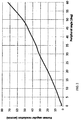
- FIG. 2 shows the angular resolution of a typical human eye as a function of the peripheral angle (according to J.J. Kerr, "Visual resolution in the periphery", Perception & Psychophysics, Vol. 9 (3), 1971 ). If a spherical angular coordinate system is considered with the pole at the gazing vector (so the peripheral angle coincides with the polar angle), the angular resolution has no dependence on the azimuth. Moreover, the human vision resolution is approximately isotropic, which means that the capacity to distinguish two point sources does not depend on the orientation of the line joining the two point sources.
- the focal length across the virtual screen which fixes the magnification from opixels to ipixels
- the control of ipixels size must be done in two dimensions because the human resolution is isotropic.
- the ratio of the angular rms diameter of the spot at the virtual screen to the ipixel size for the worst eye pupil position should ideally be approximately equal across the virtual screen. If the optics is ray traced in the reverse direction (from the eye towards a point at the virtual screen, until reaching the display), this adaptation of the optical quality implies that the ratio of the rms diameter of the spot at the digital display to the opixel size for the worst eye pupil position should ideally be approximately equal across the display (even though the focal length varies).
- Section 5 will describe embodiments with rotationally symmetric optics which can only control the ipixels size in the radial direction, while section 6 will describe embodiments with freeform optics (i.e., without rotational symmetry) which will control the ipixels size in their two dimensions.
- mapping function ( ⁇ , ⁇ ) be the polar coordinates of a point r on the digital display and let ⁇ , ⁇ be the polar and azimuthal angles, respectively, of the spherical coordinates on the virtual screen.
- the function r ( ⁇ , ⁇ ) ( ⁇ ( ⁇ , ⁇ )cos( ⁇ ( ⁇ , ⁇ )), ⁇ ( ⁇ , ⁇ )sin( ⁇ ( ⁇ , ⁇ ))) is called the mapping function.
- the radial focal length f rad at the virtual screen direction ( ⁇ , ⁇ ) is
- the focal length informs about the expansion or shrinking of the mapping in a particular direction.
- f ⁇ is independent of ⁇ which is equivalent to saying that the mapping expansion or shrinking is isotropic.
- the human eye resolution depends on the peripheral angle but it is isotropic in good approximation, it is not dependent on the direction ⁇ along which the resolution is evaluated. Then it is desirable that the angular extent of the ipixels be independent of ⁇ (otherwise the resolution will be given by the greatest angular diameter). Since the diameter of the opixels is in general quite constant with ⁇ then an f ⁇ independent of ⁇ is in general desirable.
- and the sagittal focal length is f sag ⁇ /sin ⁇ .
- the radial focal length f rad is a decreasing function with an approximately constant slope with ⁇ outside the gazed region of the virtual screen, so the ipixels at least are significantly larger in the radial direction there, showing a better adaptation of the focal length to the resolution of human eye, Moreover, the imaging quality of the optical system is also approximately adapted to the resolution of the eye.
- the rectilinear mapping 302 is below the linear mapping 303 for all angles, while the curve of adapted design 301 is above the linear mapping 303.
- curve 301 starts at the origin with a derivative higher than the ratio ⁇ end / ⁇ end but ends at the point ⁇ end , ⁇ end with a smaller derivative than the ratio ⁇ end / ⁇ end , in contrast to what occurs to the linear mapping curve 303.
- the selected parameters are the focal lengths, angular size of the ipixels, ipixel density (in ipixels per degree) and Nyquist frequency on the virtual screen (which is the angular frequency of the on-off sequence of ipixels).
- the ipixel size of the adapted embodiment is 3 arcmin, about 1.5 times smaller than the linear case and more than 2 times as small as in the rectilinear one.
- the 3 arcmin ipixels are still distinguishable (since the human eye resolves 2 arcmin as indicated in FIG. 2 ) but, but they are less distinguishable than with the other two mappings.
- the radial size of the ipixel in the adapted embodiment is 28 arcmin, about 6 times as large as in the linear case and 7 times as large as in the rectilinear case.
- 28 arcmin seems a high value
- the peripheral angle is 50°
- resolution limit of the human vision is 50 arcmin (see FIG. 2 )
- the coarseness of the resolution will not be seen.
- the human vision reolution is 30 arcmin, close to the 28 arcmin of the adapted embodiment.
- the sagittal focal length f sag ⁇ /sin ⁇ (not shown in FIG. 4 ) is not reduced as much as the radial focal length in this rotationally symmetric design.
- the ipixels in the peripheral region are strongly elongated in the radial direction in this adapted design. Only breaking the rotational symmetry can take full advantage of an adapted resolution because both focal lengths can take closer values, as will be disclosed in section 7.
- the adapted mapping curve 301 can be realized with a system using multiple rotationally symmetrical optical surfaces, provided that the number of aspheric surfaces is sufficient (preferably, 4 or more). When the number of surfaces is increased, the degrees of freedom are higher and the adaption can be better achieved, while designs with fewer surfaces may have more limited optical performance and thus a less pronounced slope of the mapping 301.
- FIG. 5 shows the perspective view of a 2-lens design that provides the adapted mapping and radial focal distance values given in FIG. 3 and FIG. 4 .
- a respective lens pair composed by refractive lenses 503 and 504, is placed between each eye 501 and the display 502.
- Each half of the display (divided by central line 505) works with one eye. Due to the particular dimensions of the 16:9 display used for this design (5.7", 145 mm, diagonal), the center of each eye for the average standard interpupil distance is aligned with the center of the respective half of the display 506.
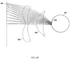
- FIG. 6A is a 2D cross-section of the two lens adapted design, showing the profile of the eye 601, the display 602, and both lenses 603 and 604.
- Reversed rays for different ipixels have been plotted, going from a notional eye pupil 605 (displaced to the center of the eye to simplify the geometry) towards the display, impinging on different opixels, for different ipixels.
- This eye pupil 605 allows us to simulate the performance of the ipixels when they are gazed while the eye is rotated, and these gazed ipixels are therefore the ipixels whose performance should be the best. Raytrace simulation results for the case in FIG.
- FIG. 6B is the same 2D cross-section but the rays shown correspond to those captured by the eye pupil when the eye is gazing frontwards.
- the image quality of these rays can be progressively relaxed when the peripheral angle increases, as permitted by the decreasing human eye resolution.
- any ray will enter the eye only if the actual pupil (which has a typical diameter of only about 3 mm in good lighting) is at the point where the ray meets the eye sphere. If the ray is approximately radial to the eye sphere 601 at the point where the ray meets the pupil, the ray will reach the fovea. If the ray is oblique to the sphere at the point where the ray meets the pupil, of impact the ray will reach the peripheral retina. An angle of incidence of about 2.5 degrees, which corresponds to a peripheral angle also about 2.5 degrees, because the gaze direction is approximately a radius through the pupil center, may be taken as the limit of the foveal rays.
- a 0 is the vertex position along the optical axis (measured from the display)
- k is the conic constant
- ⁇ 1 / R
- R the radius at the apex
- g 2i+4 are the coefficients of Forbes Q-con polynomials Q i con ( Forbes, Shape specification for axially symmetric optical surfaces, Optics Express, Vol.
- this fitting parameter for the lens in FIG. 6A all in mm except k adimensional and ⁇ in mm -1 , are given in the following Table 3, where the surfaces are ordered as S1 to S4 in the sequence the light rays hit them in their propagation from the display to the eye.
- the distance from the display to the eye pupil when the eye is gazing frontwards is 64.94 mm.
- the z axis of the coordinate system is pointing from the eye to the display, and the origin is at the intersection of the z axis with the display.
- Lens materials are polymethyl methacrylate (PMMA) for lens 604 and polystyrene (PS) for lens 603.
- FIG. 7A is a perpective view of the embodiment where we can see the eye sphere 701, optical devices 702 and 703, which in general could be lens surfaces, double-sided lenses or any other optical device.
- the display has not been plotted for the sake of clarity in the drawing, but sectors as those identified in 703 are also identified as clusters.
- Optical devices 702 and 703 present central regions 714 and 715 which work together, while the remaining area of both devices is divided in sectors.
- the sectors belonging to 702 are distributed along an external ring, while the sectors of 703 are distributed along two different external rings.
- the angular extent in the sagittal direction of the sectors of 702 is half of the angular extent in the sagittal direction of the sectors of 703.
- the angular extent in the tangential direction of the sectors of 702 is double the angular extent in the tangential direction of the sectors in 703. This way, the sectors tessellate conveniently and so do the clusters on the digital display.
- FIG. 7B shows a front view of both optical devices 702 and 703, where 5 sectors have been highlighted in order to explain how they are arranged to work in pairs.
- sectors 704, 705, 706, 707 and 708 of device 702 work together with sectors 709, 710, 711, 712 and 713, respectively of device 703.
- sectors 704 to 708 must tessellate to guarantee that no serious gaps are seen from the eye, microlenses 709 to 713 can show gaps (so the areas indicated as 709 to 713 in FIG. 7B are just the maximum areas the sectors can occupy).
- FIG. 8 shows a cross-section of a possible realization of the embodiment in FIG. 7A , in which each of the optical devices 702 and 703 is made as a respective freeform surface of a thick lens. Therefore, sectors 704, 705, 706, 707 and 708 of surface 702 work together with sectors 709, 710, 711, 712 and 713, respectively, of surface 703, forming lenslets (704-709, 705-710, and so on).
- FIG. 8 shows the display 801, the eye 802 and three lenslets of this thick lens (all the other peripheral lenslets being superposable by rotation to one of the three lenslets shown).
- the first, central lenslet is rotationally symmetric with respect to the central axis 813 and its cross-sectional profiles 811 and 812 correspond to the central regions 714 and 715 in FIG. 7A and 7B .
- the second lenslet is a freeform lenslet that is symmetric with respect to a plane, and corresponds to the sectors 705 and 710 in FIG. 7A and 7B .
- Lines 809 and 808 in FIG. 8 are the cross-sectional profiles in its plane of symmetry that contains the axis 813 in FIG. 8 and line 717 in FIG. 7B .
- the third lenslet is also freeform, and is symmetric with respect to another plane, and corresponds to the sectors 708 and 713 in FIG. 7A and 7B .
- Lines 806 and 807 in FIG. 8 are the cross-sectional profiles in its plane of symmetry that contains the axis 813 in FIG. 8 and line 716 in FIG. 7B . Notice that the profiles of the second and third lenslets are not coplanar, and they are drawn together in FIG. 8 for this explanation only. Besides that, the ray trajectories will be reversed so light in this explanation travels from the eye to the digital display.
- the reversed ray 810 travels from the eye through the central part 812, 811 of the lens and impinges on the central part of the display 801.
- reversed fans of rays 803 and 804 are transmitted through peripheral regions 806-807 and 808-809 of the lens and impinge on the external region of the display 805.
- Ray fan 804 (plotted with dashed lines) impinges on dashed surface 808 and then on dashed surface 809, and is directed towards the display.
- ray fan 803 (plotted with continuous lines) impinges on surface 806 and then on surface 807, and is directed towards the display. Notice that the pair of surfaces 808-809 collect reversed rays with smaller peripheral angles than the pair of surfaces 806-807.
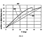
- FIG. 9 illustrates this, showing the schematic curve of the mapping function 901 of this freeform embodiment along the planes of symmetry.
- the curve 901 may be discontinuous at the boundaries between the lenslets, but if the discontinuity is well-designed the gradient of the curve may be continuous even if the curve itself is not.
- the step corresponding to the boundary between ray fans 804 and 803 is shown dotted in FIG. 9 to emphasize that it is, at least in the ideal case, a discontinuity, and not a segment of negative slope. Any departure from that ideal, for example, from rounding of the cusp between the lenslets, is preferably kept to a minimum, because it represents a place where light rays can scatter in undesired directions and deteriorate the quality of the image.
Landscapes
- Physics & Mathematics (AREA)
- General Physics & Mathematics (AREA)
- Optics & Photonics (AREA)
- Engineering & Computer Science (AREA)
- Multimedia (AREA)
- Signal Processing (AREA)
- Computer Graphics (AREA)
- Theoretical Computer Science (AREA)
- Lenses (AREA)
- Testing, Inspecting, Measuring Of Stereoscopic Televisions And Televisions (AREA)
- Control Of Indicators Other Than Cathode Ray Tubes (AREA)
- Devices For Indicating Variable Information By Combining Individual Elements (AREA)
Claims (10)
- Eine Anzeigevorrichtung, die Folgendes beinhaltet:eine Anzeige, die betriebsfähig ist, ein reelles Bild zu erzeugen; undein optisches System, das angeordnet ist, aus einem reellen Bild auf der Anzeige durch Projizieren von Licht von der Anzeige auf eine Augenposition ein virtuelles Bild zu erzeugen;wobei das virtuelle Bild sich in einem Abstand zu der Augenposition befindet undwobei die Strahlen des projizierten Lichts sowohl periphere als auch foveale Strahlen beinhalten, wobei die fovealen Strahlen diejenigen sind, die einen Winkel von weniger als 2,5° zu einer radialen Richtung der Augensphäre an dem Punkt, wo der entsprechende Strahl die Augensphäre trifft, bilden und die peripheren Strahlen diejenigen sind, die die periphere Retina erreichen; undwobei die Auflösung des virtuellen Bilds, das durch die fovealen Strahlen hergestellt wird, höher ist als diejenige, die durch die peripheren Strahlen hergestellt wird.
- Anzeigevorrichtung gemäß Anspruch 1, wobei das optische System mehr als eine Mikrolinse beinhaltet, die eine Anordnung bildet, wobei jede einzelne der Mikrolinsen angeordnet ist, ein virtuelles Unterbild aus einem entsprechenden reellen Teilbild auf der Anzeige zu erzeugen, dadurch, dass jede Mikrolinse Licht von der Anzeige zu der Augenposition projiziert;
wobei die Unterbilder sich vereinen, um das virtuelle Bild zu bilden, das von der Augenposition sichtbar ist. - Anzeigevorrichtung gemäß Anspruch 1, wobei sich eine radiale Brennweite des optischen Systems mit einem zunehmenden radialen Winkel in einer Region des virtuellen Bildes, die einen radialen Winkel von mehr als 20° von der Vorwärtsrichtung aufweist, verringert.
- Anzeigevorrichtung gemäß Anspruch 1, wobei sich eine radiale Brennweite des optischen Systems mit einem zunehmenden radialen Winkel bei im Wesentlichen allen Punkten des virtuellen Bildes, die einen radialen Winkel von mehr als 20° von der Vorwärtsrichtung aufweisen, verringert.
- Anzeigevorrichtung gemäß Anspruch 1, wobei sich auch die sagittale Brennweite des optischen Systems mit einem zunehmenden radialen Winkel in einer Region des virtuellen Bilds, die einen radialen Winkel von mehr als 20° von der Vorwärtsrichtung aufweist, verringert und sich optional die sagittale Brennweite des optischen Systems mit einem zunehmenden radialen Winkel bei im Wesentlichen allen Punkten des virtuellen Bilds, die einen radialen Winkel von mehr als 20° von der Vorwärtsrichtung aufweisen, verringert.
- Anzeigevorrichtung gemäß Anspruch 2, wobei mindestens eines der virtuellen Unterbilder den fovealen Teil enthält, wobei der foveale Teil in dem virtuellen Unterbild eine höhere Auflösung aufweist als ein peripherer Teil des virtuellen Unterbilds.
- Anzeigevorrichtung gemäß Anspruch 2, die angeordnet ist, aus mindestens einer der Mikrolinsen ein foveales virtuelles Unterbild herzustellen, das mindestens ein Abschnitt des fovealen Teils des virtuellen Bilds ist, und aus mindestens einer anderen der Mikrolinsen ein peripheres virtuelles Unterbild herzustellen, das mindestens ein Abschnitt des peripheren Teils des virtuellen Bilds ist, wobei das foveale virtuelle Unterbild eine höhere Auflösung aufweist als das periphere virtuelle Unterbild.
- Anzeigevorrichtung gemäß Anspruch 2, wobei das optische System ein erstes optisches Element mit einem ersten Ring von optisch unterschiedlichen ersten Unterelementen, ein zweites optisches Element mit zweiten und dritten Ringen von optisch unterschiedlichen zweiten und dritten Unterelementen beinhaltet, wobei alternative Unterelemente in dem ersten Ring mit nachfolgenden Unterelementen in dem zweiten Ring entsprechende Mikrolinsen bilden und verbliebene Unterelemente in dem ersten Ring mit nachfolgenden Unterelementen in dem dritten Ring entsprechende Mikrolinsen bilden und wobei das erste und zweite optische Element gegenüberliegende Freiformoberflächen einer dicken Linse sind.
- Eine Kopfbedeckung, die die Anzeigevorrichtung gemäß Anspruch 1 beinhaltet, die eine Halterung zum Positionieren der Anzeigevorrichtung auf einem menschlichen Kopf aufweist, wobei die Augenposition der Anzeigevorrichtung mit einem Auge des Menschen zusammenfällt; und die ferner eine zweite Anzeigevorrichtung beinhaltet, welche so montiert ist, dass die Augenposition der zweiten Anzeigevorrichtung mit einem zweiten Auge des Menschen zusammenfällt; und wobei die Anzeigevorrichtung und die zweite Anzeigevorrichtung optional im Wesentlichen gleich sind; und wobei die Anzeige der Anzeigevorrichtung und die Anzeige der zweiten Anzeigevorrichtung optional Teile einer einzelnen Anzeige sind.
- Anzeigevorrichtung gemäß Anspruch 2, wobei das optische System angeordnet ist, die virtuellen Unterbilder durch Beinhalten einer Freiformmikrolinse herzustellen, die eine Brennweite aufweist, die über einen aktiven Bereich der Freiformmikrolinse variiert.
Applications Claiming Priority (3)
| Application Number | Priority Date | Filing Date | Title |
|---|---|---|---|
| US201562105905P | 2015-01-21 | 2015-01-21 | |
| US201562208235P | 2015-08-21 | 2015-08-21 | |
| PCT/US2016/014163 WO2016118648A1 (en) | 2015-01-21 | 2016-01-20 | Imaging optics adapted to the human eye resolution |
Publications (4)
| Publication Number | Publication Date |
|---|---|
| EP3248049A1 EP3248049A1 (de) | 2017-11-29 |
| EP3248049A4 EP3248049A4 (de) | 2018-10-31 |
| EP3248049B1 true EP3248049B1 (de) | 2020-10-21 |
| EP3248049B8 EP3248049B8 (de) | 2020-12-30 |
Family
ID=56417699
Family Applications (3)
| Application Number | Title | Priority Date | Filing Date |
|---|---|---|---|
| EP16740692.5A Active EP3248049B8 (de) | 2015-01-21 | 2016-01-20 | An die auflösung des menschlichen auges adaptierte bildgebungsoptik |
| EP16740685.9A Active EP3248052B8 (de) | 2015-01-21 | 2016-01-20 | Visuelle anzeige mit zeitmultiplex |
| EP16740687.5A Active EP3248053B1 (de) | 2015-01-21 | 2016-01-20 | Anzeigevorrichtung mit vollständiger interner reflexion |
Family Applications After (2)
| Application Number | Title | Priority Date | Filing Date |
|---|---|---|---|
| EP16740685.9A Active EP3248052B8 (de) | 2015-01-21 | 2016-01-20 | Visuelle anzeige mit zeitmultiplex |
| EP16740687.5A Active EP3248053B1 (de) | 2015-01-21 | 2016-01-20 | Anzeigevorrichtung mit vollständiger interner reflexion |
Country Status (6)
| Country | Link |
|---|---|
| US (5) | US10436951B2 (de) |
| EP (3) | EP3248049B8 (de) |
| JP (3) | JP6670840B2 (de) |
| KR (3) | KR102549397B1 (de) |
| CN (4) | CN107430277B (de) |
| WO (5) | WO2016118640A1 (de) |
Families Citing this family (94)
| Publication number | Priority date | Publication date | Assignee | Title |
|---|---|---|---|---|
| US20160364426A1 (en) * | 2015-06-11 | 2016-12-15 | Sap Se | Maintenance of tags assigned to artifacts |
| US10567745B2 (en) | 2016-02-12 | 2020-02-18 | The Void, LLC | Head mount display with automatic inter-pupillary distance adjustment |
| US10422976B2 (en) | 2016-02-26 | 2019-09-24 | Samsung Electronics Co., Ltd. | Aberration corrected optical system for near-eye displays |
| US20170262020A1 (en) * | 2016-03-10 | 2017-09-14 | The Void Llc | Head Mount Display with Near-Eye Projection for Virtual Reality System |
| WO2017166210A1 (zh) * | 2016-03-31 | 2017-10-05 | 华为技术有限公司 | 应用程序的处理方法及终端设备 |
| GB2550137A (en) * | 2016-05-09 | 2017-11-15 | Euro Electronics (Uk) Ltd | Method and apparatus for tiles light field display |
| GB2550885A (en) * | 2016-05-26 | 2017-12-06 | Euro Electronics (Uk) Ltd | Method and apparatus for an enhanced-resolution light field display |
| US10664049B2 (en) | 2016-12-09 | 2020-05-26 | Nvidia Corporation | Systems and methods for gaze tracking |
| US11042039B1 (en) * | 2016-12-20 | 2021-06-22 | Facebook Technologies, Llc | Varifocal display with actuated reflectors |
| US10168668B2 (en) | 2016-12-21 | 2019-01-01 | Vladimir Yankov | Method of forming a rarefied hologram for video imaging and 3D lithography |
| KR102720618B1 (ko) * | 2016-12-22 | 2024-10-21 | 엘지디스플레이 주식회사 | 증강 현실 기기 |
| EP3574364B1 (de) * | 2017-01-25 | 2026-04-29 | Samsung Electronics Co., Ltd. | Kopfmontierte anzeigevorrichtung und verfahren dafür zur erzeugung von informationen eines 3d-bildes |
| US10345562B2 (en) * | 2017-02-07 | 2019-07-09 | Raytheon Company | All-reflective solar coronagraph sensor and thermal control subsystem |
| JP6980209B2 (ja) | 2017-02-22 | 2021-12-15 | ルムス エルティーディー. | 光ガイド光学アセンブリ |
| DE102017104104A1 (de) * | 2017-02-28 | 2018-08-30 | Valeo Schalter Und Sensoren Gmbh | Optisches Element für eine Sendeeinrichtung einer optischen Erfassungsvorrichtung, Sendeeinrichtung, optische Erfassungsvorrichtung, Kraftfahrzeug sowie Verfahren |
| JP6866738B2 (ja) * | 2017-04-12 | 2021-04-28 | オムロン株式会社 | 画像表示ユニット |
| DE102017111607B4 (de) * | 2017-05-29 | 2020-09-24 | tooz technologies GmbH | Abbildungsvorrichtung, Datenbrille und Verfahren zum Generieren eines Bildes aus einem Ausgangsbild in einer Datenbrille |
| CN108983488B (zh) * | 2017-06-01 | 2021-04-20 | 台达电子工业股份有限公司 | 背光模块及显示设备 |
| WO2018237263A1 (en) * | 2017-06-22 | 2018-12-27 | Tesseland Llc | Visual display with time multiplexing for stereoscopic view |
| GB2564850A (en) * | 2017-07-18 | 2019-01-30 | Euro Electronics Uk Ltd | Apparatus and method of light field display |
| CN107490847B (zh) * | 2017-08-02 | 2023-02-28 | 滕少华 | 一种旋转变焦透镜系统及其实现方法 |
| CN107300777A (zh) * | 2017-08-18 | 2017-10-27 | 深圳惠牛科技有限公司 | 一种基于双自由曲面反射的成像系统 |
| DE102017125731A1 (de) * | 2017-11-03 | 2019-05-09 | Carl Zeiss Ag | Lichtleiter, Abbildungsvorrichtung und HMD mit separaten Abbildungskanälen |
| CN107861247B (zh) * | 2017-12-22 | 2020-08-25 | 联想(北京)有限公司 | 光学部件及增强现实设备 |
| CN107966825B (zh) * | 2017-12-26 | 2023-12-19 | 广州弥德科技有限公司 | 一种拼接型指向性背光源及使用该背光源的显示系统 |
| CN108227195B (zh) * | 2017-12-29 | 2020-05-19 | 南京信息工程大学 | 一种离轴两反自由曲面光学系统 |
| US10817052B1 (en) * | 2018-01-09 | 2020-10-27 | Facebook Technologies, Llc | Eye emulator devices |
| CN208367337U (zh) * | 2018-01-16 | 2019-01-11 | 塔普翊海(上海)智能科技有限公司 | 一种ar显示设备 |
| US20210055560A1 (en) * | 2018-01-26 | 2021-02-25 | Tesseland Llc | Compact optics in crossed configuration for virtual and mixed reality |
| CN108333748B (zh) * | 2018-02-24 | 2021-01-26 | 京东方科技集团股份有限公司 | 一种虚拟现实设备的透镜优化方法和装置 |
| US10527863B2 (en) | 2018-03-16 | 2020-01-07 | Sharp Kabushiki Kaisha | Compact head-mounted display system |
| US20190293950A1 (en) * | 2018-03-22 | 2019-09-26 | Lightspace Technologies, SIA | Near-eye display apparatus and method of displaying three-dimensional images |
| US12072493B2 (en) * | 2018-03-22 | 2024-08-27 | Lightspace Technologies, SIA | Near-eye display apparatus and method of displaying three-dimensional images |
| CN108398788B (zh) * | 2018-03-23 | 2024-04-16 | 京东方科技集团股份有限公司 | 眼睛跟踪装置及虚拟现实成像设备 |
| EP3620844B1 (de) | 2018-04-23 | 2023-07-26 | Sony Group Corporation | Optisches okularsystem, medizinischer betrachter und medizinisches betrachtungssystem |
| US11454783B2 (en) | 2018-04-25 | 2022-09-27 | Samsung Electronics Co., Ltd. | Tiled triplet lenses providing a wide field of view |
| CN112189161B (zh) | 2018-04-27 | 2022-09-13 | 特塞兰德有限责任公司 | 适应人视觉的光场显示器 |
| US10497320B1 (en) * | 2018-05-07 | 2019-12-03 | Facebook Technologies, Llc | Transparent and reflective illumination source |
| WO2019220330A1 (en) | 2018-05-14 | 2019-11-21 | Lumus Ltd. | Projector configuration with subdivided optical aperture for near-eye displays, and corresponding optical systems |
| US11442273B2 (en) * | 2018-05-17 | 2022-09-13 | Lumus Ltd. | Near-eye display having overlapping projector assemblies |
| US11415812B2 (en) | 2018-06-26 | 2022-08-16 | Lumus Ltd. | Compact collimating optical device and system |
| KR102634595B1 (ko) * | 2018-07-18 | 2024-02-07 | 삼성디스플레이 주식회사 | 증강 현실 제공 장치 및 그 제조방법 |
| US20200033613A1 (en) * | 2018-07-26 | 2020-01-30 | Varjo Technologies Oy | Display apparatus and method of displaying using curved optical combiner |
| IL280934B2 (en) | 2018-08-26 | 2023-10-01 | Lumus Ltd | Suppression of reflection in displays close to the eyes |
| US11448886B2 (en) | 2018-09-28 | 2022-09-20 | Apple Inc. | Camera system |
| US11187914B2 (en) * | 2018-09-28 | 2021-11-30 | Apple Inc. | Mirror-based scene cameras |
| JP7001042B2 (ja) * | 2018-11-08 | 2022-01-19 | 日本電信電話株式会社 | 眼情報推定装置、眼情報推定方法、プログラム |
| CN109375381B (zh) * | 2018-11-27 | 2021-09-07 | 浙江理工大学 | 一种高信息通量低串扰的三维显示方法和系统 |
| US10866412B2 (en) | 2018-12-07 | 2020-12-15 | Sharp Kabushiki Kaisha | Compact head-mounted display system |
| CN109752852B (zh) * | 2018-12-12 | 2021-04-13 | 重庆爱奇艺智能科技有限公司 | 一种用于头戴式设备的显示系统及其设计方法 |
| KR102688077B1 (ko) * | 2018-12-12 | 2024-07-25 | 삼성디스플레이 주식회사 | 증강 현실 제공 장치 |
| TWI683136B (zh) * | 2019-01-03 | 2020-01-21 | 宏碁股份有限公司 | 視訊穿透式頭戴顯示器及其控制方法 |
| US11237389B1 (en) * | 2019-02-11 | 2022-02-01 | Facebook Technologies, Llc | Wedge combiner for eye-tracking |
| US10867538B1 (en) * | 2019-03-05 | 2020-12-15 | Facebook Technologies, Llc | Systems and methods for transferring an image to an array of emissive sub pixels |
| US11340459B2 (en) * | 2019-03-07 | 2022-05-24 | Rockwell Collins, Inc. | Steerable reticle for visor projected helmet mounted displays |
| WO2020183229A1 (en) | 2019-03-12 | 2020-09-17 | Lumus Ltd. | Image projector |
| CN111999889B (zh) * | 2019-05-11 | 2025-04-01 | 京东方科技集团股份有限公司 | 曲面透镜和显示装置 |
| IL289411B2 (en) | 2019-06-27 | 2025-07-01 | Lumus Ltd | Device and methods for eye tracking based on eye imaging using a light-conducting optical component |
| US11281005B2 (en) | 2019-08-08 | 2022-03-22 | Sharp Kabushiki Kaisha | Compact head-mounted display system with orthogonal panels |
| KR102503261B1 (ko) * | 2019-09-27 | 2023-02-24 | 애플 인크. | 렌티큘러 디스플레이를 동작시키기 위한 방법 및 디바이스 |
| WO2021113825A1 (en) * | 2019-12-05 | 2021-06-10 | Limbak 4Pi S.L. | Lenslet based ultra-high resolution optics for virtual and mixed reality |
| US20230023525A1 (en) * | 2020-01-08 | 2023-01-26 | Letinar Co., Ltd | Optical device for augmented reality using total internal reflection |
| KR20230004553A (ko) | 2020-04-30 | 2023-01-06 | 루머스 리미티드 | 광학 샘플 특성화 |
| IT202000012721A1 (it) | 2020-05-28 | 2021-11-28 | Sifi Spa | Lente ad uso oftalmico |
| CA3189574A1 (en) * | 2020-07-16 | 2022-01-20 | Lusospace, Projectos Engenharia Lda | Head-mounted display device |
| US11493772B1 (en) | 2020-07-22 | 2022-11-08 | Meta Platforms Technologies, Llc | Peripheral light field display |
| US20230386373A1 (en) | 2020-10-13 | 2023-11-30 | Tesseland Llc | Display device with dark ring illumination of lenslet arrays for vr and ar |
| KR20220100741A (ko) * | 2021-01-08 | 2022-07-18 | 삼성디스플레이 주식회사 | 표시 패널, 표시 장치 및 표시 장치 제어 방법 |
| US11947134B2 (en) | 2021-01-22 | 2024-04-02 | National Taiwan University | Device of generating 3D light-field image |
| KR102835526B1 (ko) | 2021-02-05 | 2025-07-18 | 삼성디스플레이 주식회사 | 표시 장치, 이를 포함하는 헤드 마운트 표시 시스템 및 이의 구동 방법 |
| WO2022175813A1 (en) * | 2021-02-17 | 2022-08-25 | 3M Innovative Properties Company | Foveated optical lens for near eye display |
| WO2022185308A1 (en) * | 2021-03-04 | 2022-09-09 | Rail Vision Ltd | System and method for verifying a selection of an optical sensor |
| KR20220136561A (ko) * | 2021-03-31 | 2022-10-11 | 삼성디스플레이 주식회사 | 표시 장치 및 표시 장치 제어 방법 |
| TW202332964A (zh) * | 2021-06-24 | 2023-08-16 | 美商元平台技術有限公司 | 用於vr/ar的頭戴式裝置的自由形式光場顯示器 |
| US11740473B2 (en) | 2021-06-24 | 2023-08-29 | Meta Platforms Technologies, Llc | Flexible displays for VR/AR headsets |
| KR102676604B1 (ko) | 2021-07-04 | 2024-06-18 | 루머스 리미티드 | 시야의 다양한 부분을 제공하는 적층형 도광 요소를 갖는 디스플레이 |
| CN117795287A (zh) * | 2021-08-13 | 2024-03-29 | 国立大学法人东京大学 | 信息处理装置、计算机程序以及模式代码 |
| KR20230040438A (ko) | 2021-09-15 | 2023-03-23 | 삼성디스플레이 주식회사 | 표시 장치 |
| JP7786092B2 (ja) * | 2021-09-16 | 2025-12-16 | 株式会社リコー | 伝搬光学系、光学系、虚像表示装置及びヘッドマウントディスプレイ |
| US12339456B2 (en) * | 2021-11-23 | 2025-06-24 | Boe Technology Group Co., Ltd. | Near-eye display apparatus |
| CN116413911B (zh) * | 2021-12-31 | 2025-08-01 | 北京耐德佳显示技术有限公司 | 一种超薄型镜片、使用其的虚像成像装置和近眼显示器 |
| US12244974B1 (en) * | 2022-01-11 | 2025-03-04 | Noah Buffett-Kennedy | Vehicular projection system |
| US12322139B2 (en) * | 2022-02-28 | 2025-06-03 | Basis Software, Inc. | System and method for camera calibration |
| KR20230150415A (ko) | 2022-04-21 | 2023-10-31 | 삼성디스플레이 주식회사 | 표시 장치 및 표시 장치 제어 방법 |
| US12450777B2 (en) * | 2022-06-01 | 2025-10-21 | Proprio, Inc. | Methods and systems for calibrating and/or verifying a calibration of an imaging system such as a surgical imaging system |
| KR20230174355A (ko) | 2022-06-20 | 2023-12-28 | 삼성디스플레이 주식회사 | 표시 장치 및 그 제어방법 |
| US20240004199A1 (en) * | 2022-07-01 | 2024-01-04 | Google Llc | Partially curved lightguide with pupil replicators |
| EP4524622A4 (de) | 2022-07-21 | 2025-08-20 | Samsung Electronics Co Ltd | Linse auf basis eines menschlichen visuellen systems, videodurchsichtsvorrichtung damit und verfahren zum entwerfen einer linse |
| KR20240041419A (ko) | 2022-09-22 | 2024-04-01 | 삼성디스플레이 주식회사 | 표시 장치 및 헤드 마운트 표시 장치 |
| KR20240125760A (ko) * | 2023-02-09 | 2024-08-20 | 삼성디스플레이 주식회사 | 화질 검사 방법, 이를 수행하는 화질 검사 시스템 및 화질 검사 방법이 적용되는 표시 장치 |
| US12293548B2 (en) * | 2023-04-21 | 2025-05-06 | Toyota Research Institute, Inc. | Systems and methods for estimating scaled maps by sampling representations from a learning model |
| US20250093646A1 (en) * | 2023-09-15 | 2025-03-20 | Apple Inc. | Hybrid Folded Birdbath Display |
| WO2025096833A1 (en) * | 2023-10-31 | 2025-05-08 | Universal City Studios Llc | Systems and methods for projection mapping onto multiple rigid bodies |
| US12491907B1 (en) * | 2024-01-18 | 2025-12-09 | Zoox, Inc. | Time simulation management of real world sensor frame data |
Family Cites Families (84)
| Publication number | Priority date | Publication date | Assignee | Title |
|---|---|---|---|---|
| ATE54768T1 (de) * | 1985-01-24 | 1990-08-15 | Cerberus Ag | Infrarot-einbruchdetektor. |
| JPH0584930U (ja) | 1992-04-23 | 1993-11-16 | 神鋼電機株式会社 | 表示素子及びそれを用いた表示装置 |
| JPH0638219A (ja) * | 1992-07-20 | 1994-02-10 | Olympus Optical Co Ltd | 映像表示装置 |
| US5326266A (en) * | 1992-09-02 | 1994-07-05 | Evans & Sutherland Computer Corporation | Area of interest display system with opto/mechanical image combining |
| JPH08160344A (ja) | 1994-12-05 | 1996-06-21 | Olympus Optical Co Ltd | 頭部装着式映像表示装置 |
| JP3658034B2 (ja) | 1995-02-28 | 2005-06-08 | キヤノン株式会社 | 画像観察光学系及び撮像光学系 |
| JP3599828B2 (ja) | 1995-05-18 | 2004-12-08 | オリンパス株式会社 | 光学装置 |
| JPH0965245A (ja) | 1995-08-21 | 1997-03-07 | Olympus Optical Co Ltd | 画像表示装置 |
| JP3371654B2 (ja) * | 1995-10-30 | 2003-01-27 | ソニー株式会社 | 投射型ディスプレイ装置 |
| JPH09219832A (ja) * | 1996-02-13 | 1997-08-19 | Olympus Optical Co Ltd | 画像表示装置 |
| US5838490A (en) | 1996-11-04 | 1998-11-17 | Honeywell Inc. | Head mounted display system using mangin mirror combiner |
| JP3943680B2 (ja) | 1997-01-06 | 2007-07-11 | オリンパス株式会社 | 映像表示装置 |
| US20040108971A1 (en) | 1998-04-09 | 2004-06-10 | Digilens, Inc. | Method of and apparatus for viewing an image |
| EP1465003B1 (de) * | 1999-04-02 | 2008-12-31 | Olympus Corporation | Optisches Sichtgerät und Bildanzeige mit diesem Gerät |
| WO2001048536A2 (en) * | 1999-12-23 | 2001-07-05 | Shevlin Technologies Limited | A display device |
| JP4573393B2 (ja) * | 2000-01-06 | 2010-11-04 | オリンパス株式会社 | 画像表示装置 |
| JP2002040364A (ja) * | 2000-07-21 | 2002-02-06 | Asahi Optical Co Ltd | 立体視観察用光学系 |
| KR100388819B1 (ko) | 2000-07-31 | 2003-06-25 | 주식회사 대양이앤씨 | 헤드 마운트 디스플레이용 광학 시스템 |
| US6543899B2 (en) * | 2000-12-05 | 2003-04-08 | Eastman Kodak Company | Auto-stereoscopic viewing system using mounted projection |
| DE10103922A1 (de) * | 2001-01-30 | 2002-08-01 | Physoptics Opto Electronic Gmb | Interaktives Datensicht- und Bediensystem |
| US6522474B2 (en) * | 2001-06-11 | 2003-02-18 | Eastman Kodak Company | Head-mounted optical apparatus for stereoscopic display |
| US7053967B2 (en) * | 2002-05-23 | 2006-05-30 | Planar Systems, Inc. | Light sensitive display |
| JP3994896B2 (ja) * | 2002-09-25 | 2007-10-24 | コニカミノルタホールディングス株式会社 | 映像表示装置 |
| US6896381B2 (en) * | 2002-10-11 | 2005-05-24 | Light Prescriptions Innovators, Llc | Compact folded-optics illumination lens |
| JP2004258332A (ja) | 2003-02-26 | 2004-09-16 | Canon Inc | 頭部装着型画像表示装置 |
| JP2004317798A (ja) * | 2003-04-16 | 2004-11-11 | Canon Inc | 画像表示装置 |
| US7495638B2 (en) * | 2003-05-13 | 2009-02-24 | Research Triangle Institute | Visual display with increased field of view |
| ITTO20030734A1 (it) * | 2003-09-24 | 2005-03-25 | Fiat Ricerche | Concentratore di luce multifocale per un dispositivo per la conversione di radiazione, ed in particolare per la conversione della radiazione solare in energia elettrica, termica o chimica. |
| CA2548224A1 (en) * | 2003-12-12 | 2005-07-07 | Headplay, Inc. | Multiple imaging arrangements for head mounted displays |
| JP2006329747A (ja) * | 2005-05-25 | 2006-12-07 | Tokyo Institute Of Technology | 画像撮影装置 |
| KR101170120B1 (ko) | 2005-07-27 | 2012-07-31 | 삼성전자주식회사 | 비안경식 3차원 디스플레이 장치 |
| WO2007019347A2 (en) * | 2005-08-08 | 2007-02-15 | University Of Connecticut | Depth and lateral size control of three-dimensional images in projection integral imaging |
| KR100716829B1 (ko) * | 2005-08-10 | 2007-05-09 | 삼성전기주식회사 | 초박형 모바일 카메라 광학 렌즈 시스템 및 이를 이용한이미지 결상 방법 |
| US7486341B2 (en) * | 2005-11-03 | 2009-02-03 | University Of Central Florida Research Foundation, Inc. | Head mounted display with eye accommodation having 3-D image producing system consisting of, for each eye, one single planar display screen, one single planar tunable focus LC micro-lens array, one single planar black mask and bias lens |
| US7515345B2 (en) * | 2006-10-09 | 2009-04-07 | Drs Sensors & Targeting Systems, Inc. | Compact objective lens assembly |
| JP2008165063A (ja) | 2006-12-28 | 2008-07-17 | Scalar Corp | ヘッドマウントディスプレイ |
| US8605008B1 (en) | 2007-05-04 | 2013-12-10 | Apple Inc. | Head-mounted display |
| JP5031452B2 (ja) | 2007-06-20 | 2012-09-19 | キヤノン株式会社 | 画像観察装置及び画像観察システム |
| JP4906680B2 (ja) | 2007-11-02 | 2012-03-28 | キヤノン株式会社 | 画像表示装置 |
| KR101419230B1 (ko) * | 2007-11-29 | 2014-07-16 | 엘지디스플레이 주식회사 | 입체 표시 장치 |
| EP2225601A1 (de) * | 2007-12-18 | 2010-09-08 | BAE Systems PLC | Verbesserungen an oder im zusammenhang mit projektionsanzeigen |
| IL196078A (en) * | 2007-12-20 | 2014-09-30 | Raytheon Co | Imaging system |
| US20100149073A1 (en) * | 2008-11-02 | 2010-06-17 | David Chaum | Near to Eye Display System and Appliance |
| US20090295683A1 (en) | 2008-05-27 | 2009-12-03 | Randall Pugh | Head mounted display with variable focal length lens |
| CN201242611Y (zh) * | 2008-08-12 | 2009-05-20 | 贾怀昌 | 自由曲面全反射式的目视光学棱镜 |
| CN101359089B (zh) * | 2008-10-08 | 2010-08-11 | 北京理工大学 | 轻小型大视场自由曲面棱镜头盔显示器光学系统 |
| JP5335375B2 (ja) * | 2008-10-31 | 2013-11-06 | キヤノン株式会社 | 画像表示装置 |
| JPWO2010061835A1 (ja) * | 2008-11-26 | 2012-04-26 | コニカミノルタオプト株式会社 | 映像表示装置およびヘッドマウントディスプレイ |
| JP4863527B2 (ja) * | 2009-12-01 | 2012-01-25 | 稔 稲葉 | 立体映像撮像装置 |
| WO2010123934A1 (en) * | 2009-04-20 | 2010-10-28 | The Arizona Board Of Regents On Behalf Of The University Of Arizona | Optical see-through free-form head-mounted display |
| JP2011145488A (ja) | 2010-01-14 | 2011-07-28 | Sony Corp | ヘッドマウントディスプレイ |
| CN102782562B (zh) * | 2010-04-30 | 2015-07-22 | 北京理工大学 | 宽视场高分辨率拼接式头盔显示装置 |
| CN101887166B (zh) * | 2010-07-15 | 2012-07-11 | 深圳航天科技创新研究院 | 目镜 |
| CN101915992B (zh) * | 2010-07-23 | 2012-05-16 | 浙江大学 | 一种基于自由曲面护目镜的穿透式头盔显示装置 |
| US8717562B2 (en) * | 2010-08-23 | 2014-05-06 | Scattering Solutions, Inc. | Dynamic and depolarized dynamic light scattering colloid analyzer |
| KR101728821B1 (ko) * | 2010-09-28 | 2017-05-04 | 삼성디스플레이 주식회사 | 3차원 표시 장치 |
| US8781794B2 (en) * | 2010-10-21 | 2014-07-15 | Lockheed Martin Corporation | Methods and systems for creating free space reflective optical surfaces |
| US8625200B2 (en) * | 2010-10-21 | 2014-01-07 | Lockheed Martin Corporation | Head-mounted display apparatus employing one or more reflective optical surfaces |
| US9406166B2 (en) | 2010-11-08 | 2016-08-02 | Seereal Technologies S.A. | Display device, in particular a head-mounted display, based on temporal and spatial multiplexing of hologram tiles |
| JP6246592B2 (ja) * | 2010-12-16 | 2017-12-13 | ロッキード マーティン コーポレーション | 画素レンズを有するコリメーティングディスプレイ |
| NZ706893A (en) * | 2010-12-24 | 2017-02-24 | Magic Leap Inc | An ergonomic head mounted display device and optical system |
| TWI432013B (zh) * | 2011-06-30 | 2014-03-21 | Acer Inc | 立體影像顯示方法及影像時序控制器 |
| JP2013044896A (ja) * | 2011-08-23 | 2013-03-04 | Brother Ind Ltd | ヘッドマウントディスプレイ |
| JP5875295B2 (ja) * | 2011-08-30 | 2016-03-02 | キヤノン株式会社 | 画像表示装置 |
| US8929589B2 (en) * | 2011-11-07 | 2015-01-06 | Eyefluence, Inc. | Systems and methods for high-resolution gaze tracking |
| CN102402005B (zh) * | 2011-12-06 | 2015-11-25 | 北京理工大学 | 自由曲面双焦面单目立体头盔显示器装置 |
| US8384999B1 (en) * | 2012-01-09 | 2013-02-26 | Cerr Limited | Optical modules |
| JP6141584B2 (ja) * | 2012-01-24 | 2017-06-07 | アリゾナ ボード オブ リージェンツ オン ビハーフ オブ ザ ユニバーシティ オブ アリゾナ | 小型視線追従型ヘッドマウントディスプレイ |
| JP6028357B2 (ja) * | 2012-03-22 | 2016-11-16 | ソニー株式会社 | ヘッドマウントディスプレイ及び手術システム |
| DE102012205164B4 (de) * | 2012-03-29 | 2021-09-09 | Fraunhofer-Gesellschaft zur Förderung der angewandten Forschung e.V. | Projektionsdisplay und Verfahren zur Projektion virtueller Bilder |
| US9142185B2 (en) * | 2012-08-30 | 2015-09-22 | Atheer, Inc. | Method and apparatus for selectively presenting content |
| CN103207454B (zh) * | 2012-09-17 | 2016-09-07 | 北京理工大学 | 具有扩展边缘的双视场自由曲面棱镜头盔显示器用光学系统 |
| CN103841395B (zh) * | 2012-11-27 | 2016-10-05 | 联想(北京)有限公司 | 合成图像显示方法和设备 |
| US10192358B2 (en) * | 2012-12-20 | 2019-01-29 | Microsoft Technology Licensing, Llc | Auto-stereoscopic augmented reality display |
| KR101294261B1 (ko) | 2013-01-08 | 2013-08-06 | 동서대학교산학협력단 | 마스크와 시간다중화 방식을 이용한 3차원 집적 영상 표시방법 |
| US10209517B2 (en) * | 2013-05-20 | 2019-02-19 | Digilens, Inc. | Holographic waveguide eye tracker |
| CN203519925U (zh) * | 2013-06-29 | 2014-04-02 | 歌尔声学股份有限公司 | 一种头戴显示器 |
| TWI470267B (zh) * | 2013-10-14 | 2015-01-21 | Largan Precision Co Ltd | 光學影像拾取系統、取像裝置以及可攜裝置 |
| WO2015077718A1 (en) | 2013-11-25 | 2015-05-28 | Tesseland Llc | Immersive compact display glasses |
| WO2015088468A1 (en) | 2013-12-09 | 2015-06-18 | Moskalenko Mykhailo | Device for representation of visual information |
| US9753288B2 (en) * | 2014-01-21 | 2017-09-05 | Osterhout Group, Inc. | See-through computer display systems |
| US10203762B2 (en) * | 2014-03-11 | 2019-02-12 | Magic Leap, Inc. | Methods and systems for creating virtual and augmented reality |
| US9895057B2 (en) * | 2014-04-24 | 2018-02-20 | Carl Zeiss Meditec, Inc. | Functional vision testing using light field displays |
| US9759919B2 (en) * | 2015-01-05 | 2017-09-12 | Microsoft Technology Licensing, Llc | Virtual image display with curved light path |
-
2016
- 2016-01-20 KR KR1020177023137A patent/KR102549397B1/ko active Active
- 2016-01-20 CN CN201680014251.2A patent/CN107430277B/zh active Active
- 2016-01-20 WO PCT/US2016/014151 patent/WO2016118640A1/en not_active Ceased
- 2016-01-20 KR KR1020177023130A patent/KR102627249B1/ko active Active
- 2016-01-20 EP EP16740692.5A patent/EP3248049B8/de active Active
- 2016-01-20 CN CN201680014252.7A patent/CN107407817B/zh active Active
- 2016-01-20 US US15/545,626 patent/US10436951B2/en active Active
- 2016-01-20 WO PCT/US2016/014155 patent/WO2016118643A1/en not_active Ceased
- 2016-01-20 JP JP2017538425A patent/JP6670840B2/ja not_active Expired - Fee Related
- 2016-01-20 US US15/545,620 patent/US10459126B2/en active Active
- 2016-01-20 US US15/545,636 patent/US10782453B2/en active Active
- 2016-01-20 WO PCT/US2016/014163 patent/WO2016118648A1/en not_active Ceased
- 2016-01-20 JP JP2017538427A patent/JP6821574B2/ja active Active
- 2016-01-20 US US15/545,633 patent/US10663626B2/en active Active
- 2016-01-20 EP EP16740685.9A patent/EP3248052B8/de active Active
- 2016-01-20 WO PCT/US2016/014160 patent/WO2016118647A1/en not_active Ceased
- 2016-01-20 US US15/545,638 patent/US10690813B2/en active Active
- 2016-01-20 KR KR1020177023126A patent/KR102549398B1/ko active Active
- 2016-01-20 CN CN201680014253.1A patent/CN107430285B/zh active Active
- 2016-01-20 EP EP16740687.5A patent/EP3248053B1/de active Active
- 2016-01-20 WO PCT/US2016/014162 patent/WO2016160099A2/en not_active Ceased
- 2016-01-20 CN CN201680014243.8A patent/CN107407816B/zh active Active
- 2016-01-20 JP JP2017538426A patent/JP6782703B2/ja active Active
Non-Patent Citations (1)
| Title |
|---|
| None * |
Also Published As
Similar Documents
| Publication | Publication Date | Title |
|---|---|---|
| EP3248049B1 (de) | An die auflösung des menschlichen auges adaptierte bildgebungsoptik | |
| EP3075150B1 (de) | Kompakte immersive anzeigegläser | |
| JP5417660B2 (ja) | 立体プロジェクション・システム | |
| KR101916079B1 (ko) | 하나 또는 그 이상의 프레넬 렌즈를 수반하는 헤드 장착 디스플레이 장치 | |
| US10495790B2 (en) | Head-mounted display apparatus employing one or more Fresnel lenses | |
| WO2021258873A1 (zh) | 光场显示装置 | |
| TWI553344B (zh) | 使用一或多個菲涅耳透鏡(fresnel lenses)之頭戴式顯示裝置 | |
| JP4761539B2 (ja) | 視覚表示装置 | |
| JP4790547B2 (ja) | 視覚表示装置 | |
| JP2008176180A (ja) | 視覚表示装置 | |
| Hua et al. | Statically Foveated Freeform OST-HMD System with Wide FOV and High Perceived Resolution | |
| Lyu | Wyant College of Optical Sciences The University of Arizona 85721-0094 Tucson AZ USA Pengyinjie Lyu✉ and Hong Hua✉ Correspondence: Hong Hua (hhua@ optics. arizona. edu) or (520-626-8703) Wyant College of Optical Sciences, The University of Arizona, Tucson, AZ 85721-0094, USA | |
| WO2025015151A1 (en) | Perceptual-driven foveated optical see-through head-mounted displays |
Legal Events
| Date | Code | Title | Description |
|---|---|---|---|
| STAA | Information on the status of an ep patent application or granted ep patent |
Free format text: STATUS: THE INTERNATIONAL PUBLICATION HAS BEEN MADE |
|
| PUAI | Public reference made under article 153(3) epc to a published international application that has entered the european phase |
Free format text: ORIGINAL CODE: 0009012 |
|
| STAA | Information on the status of an ep patent application or granted ep patent |
Free format text: STATUS: REQUEST FOR EXAMINATION WAS MADE |
|
| 17P | Request for examination filed |
Effective date: 20170818 |
|
| AK | Designated contracting states |
Kind code of ref document: A1 Designated state(s): AL AT BE BG CH CY CZ DE DK EE ES FI FR GB GR HR HU IE IS IT LI LT LU LV MC MK MT NL NO PL PT RO RS SE SI SK SM TR |
|
| AX | Request for extension of the european patent |
Extension state: BA ME |
|
| DAV | Request for validation of the european patent (deleted) | ||
| DAX | Request for extension of the european patent (deleted) | ||
| A4 | Supplementary search report drawn up and despatched |
Effective date: 20181004 |
|
| RIC1 | Information provided on ipc code assigned before grant |
Ipc: G02B 27/01 20060101AFI20180927BHEP Ipc: G06T 15/00 20110101ALI20180927BHEP |
|
| STAA | Information on the status of an ep patent application or granted ep patent |
Free format text: STATUS: EXAMINATION IS IN PROGRESS |
|
| 17Q | First examination report despatched |
Effective date: 20191128 |
|
| GRAP | Despatch of communication of intention to grant a patent |
Free format text: ORIGINAL CODE: EPIDOSNIGR1 |
|
| STAA | Information on the status of an ep patent application or granted ep patent |
Free format text: STATUS: GRANT OF PATENT IS INTENDED |
|
| INTG | Intention to grant announced |
Effective date: 20200602 |
|
| GRAS | Grant fee paid |
Free format text: ORIGINAL CODE: EPIDOSNIGR3 |
|
| GRAA | (expected) grant |
Free format text: ORIGINAL CODE: 0009210 |
|
| STAA | Information on the status of an ep patent application or granted ep patent |
Free format text: STATUS: THE PATENT HAS BEEN GRANTED |
|
| AK | Designated contracting states |
Kind code of ref document: B1 Designated state(s): AL AT BE BG CH CY CZ DE DK EE ES FI FR GB GR HR HU IE IS IT LI LT LU LV MC MK MT NL NO PL PT RO RS SE SI SK SM TR |
|
| REG | Reference to a national code |
Ref country code: GB Ref legal event code: FG4D |
|
| REG | Reference to a national code |
Ref country code: CH Ref legal event code: EP |
|
| REG | Reference to a national code |
Ref country code: IE Ref legal event code: FG4D |
|
| REG | Reference to a national code |
Ref country code: DE Ref legal event code: R081 Ref document number: 602016046234 Country of ref document: DE Owner name: TESSELAND LLC, PASADENA, US Free format text: FORMER OWNER: TESSELAND LLC, GLENDALE, CA, US Ref country code: DE Ref legal event code: R096 Ref document number: 602016046234 Country of ref document: DE |
|
| REG | Reference to a national code |
Ref country code: AT Ref legal event code: REF Ref document number: 1326397 Country of ref document: AT Kind code of ref document: T Effective date: 20201115 |
|
| RAP2 | Party data changed (patent owner data changed or rights of a patent transferred) |
Owner name: TESSELAND LLC |
|
| REG | Reference to a national code |
Ref country code: CH Ref legal event code: PK Free format text: BERICHTIGUNG B8 |
|
| REG | Reference to a national code |
Ref country code: CH Ref legal event code: NV Representative=s name: MURGITROYD AND COMPANY, CH |
|
| REG | Reference to a national code |
Ref country code: AT Ref legal event code: MK05 Ref document number: 1326397 Country of ref document: AT Kind code of ref document: T Effective date: 20201021 |
|
| REG | Reference to a national code |
Ref country code: NL Ref legal event code: MP Effective date: 20201021 |
|
| PG25 | Lapsed in a contracting state [announced via postgrant information from national office to epo] |
Ref country code: NO Free format text: LAPSE BECAUSE OF FAILURE TO SUBMIT A TRANSLATION OF THE DESCRIPTION OR TO PAY THE FEE WITHIN THE PRESCRIBED TIME-LIMIT Effective date: 20210121 Ref country code: NL Free format text: LAPSE BECAUSE OF FAILURE TO SUBMIT A TRANSLATION OF THE DESCRIPTION OR TO PAY THE FEE WITHIN THE PRESCRIBED TIME-LIMIT Effective date: 20201021 Ref country code: RS Free format text: LAPSE BECAUSE OF FAILURE TO SUBMIT A TRANSLATION OF THE DESCRIPTION OR TO PAY THE FEE WITHIN THE PRESCRIBED TIME-LIMIT Effective date: 20201021 Ref country code: PT Free format text: LAPSE BECAUSE OF FAILURE TO SUBMIT A TRANSLATION OF THE DESCRIPTION OR TO PAY THE FEE WITHIN THE PRESCRIBED TIME-LIMIT Effective date: 20210222 Ref country code: GR Free format text: LAPSE BECAUSE OF FAILURE TO SUBMIT A TRANSLATION OF THE DESCRIPTION OR TO PAY THE FEE WITHIN THE PRESCRIBED TIME-LIMIT Effective date: 20210122 Ref country code: FI Free format text: LAPSE BECAUSE OF FAILURE TO SUBMIT A TRANSLATION OF THE DESCRIPTION OR TO PAY THE FEE WITHIN THE PRESCRIBED TIME-LIMIT Effective date: 20201021 |
|
| REG | Reference to a national code |
Ref country code: LT Ref legal event code: MG4D |
|
| PG25 | Lapsed in a contracting state [announced via postgrant information from national office to epo] |
Ref country code: SE Free format text: LAPSE BECAUSE OF FAILURE TO SUBMIT A TRANSLATION OF THE DESCRIPTION OR TO PAY THE FEE WITHIN THE PRESCRIBED TIME-LIMIT Effective date: 20201021 Ref country code: AT Free format text: LAPSE BECAUSE OF FAILURE TO SUBMIT A TRANSLATION OF THE DESCRIPTION OR TO PAY THE FEE WITHIN THE PRESCRIBED TIME-LIMIT Effective date: 20201021 Ref country code: ES Free format text: LAPSE BECAUSE OF FAILURE TO SUBMIT A TRANSLATION OF THE DESCRIPTION OR TO PAY THE FEE WITHIN THE PRESCRIBED TIME-LIMIT Effective date: 20201021 Ref country code: BG Free format text: LAPSE BECAUSE OF FAILURE TO SUBMIT A TRANSLATION OF THE DESCRIPTION OR TO PAY THE FEE WITHIN THE PRESCRIBED TIME-LIMIT Effective date: 20210121 Ref country code: IS Free format text: LAPSE BECAUSE OF FAILURE TO SUBMIT A TRANSLATION OF THE DESCRIPTION OR TO PAY THE FEE WITHIN THE PRESCRIBED TIME-LIMIT Effective date: 20210221 Ref country code: LV Free format text: LAPSE BECAUSE OF FAILURE TO SUBMIT A TRANSLATION OF THE DESCRIPTION OR TO PAY THE FEE WITHIN THE PRESCRIBED TIME-LIMIT Effective date: 20201021 Ref country code: PL Free format text: LAPSE BECAUSE OF FAILURE TO SUBMIT A TRANSLATION OF THE DESCRIPTION OR TO PAY THE FEE WITHIN THE PRESCRIBED TIME-LIMIT Effective date: 20201021 |
|
| PG25 | Lapsed in a contracting state [announced via postgrant information from national office to epo] |
Ref country code: HR Free format text: LAPSE BECAUSE OF FAILURE TO SUBMIT A TRANSLATION OF THE DESCRIPTION OR TO PAY THE FEE WITHIN THE PRESCRIBED TIME-LIMIT Effective date: 20201021 |
|
| REG | Reference to a national code |
Ref country code: DE Ref legal event code: R097 Ref document number: 602016046234 Country of ref document: DE |
|
| PG25 | Lapsed in a contracting state [announced via postgrant information from national office to epo] |
Ref country code: SM Free format text: LAPSE BECAUSE OF FAILURE TO SUBMIT A TRANSLATION OF THE DESCRIPTION OR TO PAY THE FEE WITHIN THE PRESCRIBED TIME-LIMIT Effective date: 20201021 Ref country code: LT Free format text: LAPSE BECAUSE OF FAILURE TO SUBMIT A TRANSLATION OF THE DESCRIPTION OR TO PAY THE FEE WITHIN THE PRESCRIBED TIME-LIMIT Effective date: 20201021 Ref country code: CZ Free format text: LAPSE BECAUSE OF FAILURE TO SUBMIT A TRANSLATION OF THE DESCRIPTION OR TO PAY THE FEE WITHIN THE PRESCRIBED TIME-LIMIT Effective date: 20201021 Ref country code: EE Free format text: LAPSE BECAUSE OF FAILURE TO SUBMIT A TRANSLATION OF THE DESCRIPTION OR TO PAY THE FEE WITHIN THE PRESCRIBED TIME-LIMIT Effective date: 20201021 Ref country code: RO Free format text: LAPSE BECAUSE OF FAILURE TO SUBMIT A TRANSLATION OF THE DESCRIPTION OR TO PAY THE FEE WITHIN THE PRESCRIBED TIME-LIMIT Effective date: 20201021 Ref country code: SK Free format text: LAPSE BECAUSE OF FAILURE TO SUBMIT A TRANSLATION OF THE DESCRIPTION OR TO PAY THE FEE WITHIN THE PRESCRIBED TIME-LIMIT Effective date: 20201021 |
|
| PLBE | No opposition filed within time limit |
Free format text: ORIGINAL CODE: 0009261 |
|
| STAA | Information on the status of an ep patent application or granted ep patent |
Free format text: STATUS: NO OPPOSITION FILED WITHIN TIME LIMIT |
|
| PG25 | Lapsed in a contracting state [announced via postgrant information from national office to epo] |
Ref country code: MC Free format text: LAPSE BECAUSE OF FAILURE TO SUBMIT A TRANSLATION OF THE DESCRIPTION OR TO PAY THE FEE WITHIN THE PRESCRIBED TIME-LIMIT Effective date: 20201021 Ref country code: DK Free format text: LAPSE BECAUSE OF FAILURE TO SUBMIT A TRANSLATION OF THE DESCRIPTION OR TO PAY THE FEE WITHIN THE PRESCRIBED TIME-LIMIT Effective date: 20201021 |
|
| 26N | No opposition filed |
Effective date: 20210722 |
|
| PG25 | Lapsed in a contracting state [announced via postgrant information from national office to epo] |
Ref country code: LU Free format text: LAPSE BECAUSE OF NON-PAYMENT OF DUE FEES Effective date: 20210120 |
|
| REG | Reference to a national code |
Ref country code: BE Ref legal event code: MM Effective date: 20210131 |
|
| PG25 | Lapsed in a contracting state [announced via postgrant information from national office to epo] |
Ref country code: AL Free format text: LAPSE BECAUSE OF FAILURE TO SUBMIT A TRANSLATION OF THE DESCRIPTION OR TO PAY THE FEE WITHIN THE PRESCRIBED TIME-LIMIT Effective date: 20201021 Ref country code: IT Free format text: LAPSE BECAUSE OF FAILURE TO SUBMIT A TRANSLATION OF THE DESCRIPTION OR TO PAY THE FEE WITHIN THE PRESCRIBED TIME-LIMIT Effective date: 20201021 |
|
| PG25 | Lapsed in a contracting state [announced via postgrant information from national office to epo] |
Ref country code: SI Free format text: LAPSE BECAUSE OF FAILURE TO SUBMIT A TRANSLATION OF THE DESCRIPTION OR TO PAY THE FEE WITHIN THE PRESCRIBED TIME-LIMIT Effective date: 20201021 |
|
| PG25 | Lapsed in a contracting state [announced via postgrant information from national office to epo] |
Ref country code: IE Free format text: LAPSE BECAUSE OF NON-PAYMENT OF DUE FEES Effective date: 20210120 |
|
| PG25 | Lapsed in a contracting state [announced via postgrant information from national office to epo] |
Ref country code: IS Free format text: LAPSE BECAUSE OF FAILURE TO SUBMIT A TRANSLATION OF THE DESCRIPTION OR TO PAY THE FEE WITHIN THE PRESCRIBED TIME-LIMIT Effective date: 20210221 |
|
| PG25 | Lapsed in a contracting state [announced via postgrant information from national office to epo] |
Ref country code: BE Free format text: LAPSE BECAUSE OF NON-PAYMENT OF DUE FEES Effective date: 20210131 |
|
| REG | Reference to a national code |
Ref country code: DE Ref legal event code: R082 Ref document number: 602016046234 Country of ref document: DE Representative=s name: BARDEHLE PAGENBERG PARTNERSCHAFT MBB PATENTANW, DE |
|
| PG25 | Lapsed in a contracting state [announced via postgrant information from national office to epo] |
Ref country code: HU Free format text: LAPSE BECAUSE OF FAILURE TO SUBMIT A TRANSLATION OF THE DESCRIPTION OR TO PAY THE FEE WITHIN THE PRESCRIBED TIME-LIMIT; INVALID AB INITIO Effective date: 20160120 |
|
| PG25 | Lapsed in a contracting state [announced via postgrant information from national office to epo] |
Ref country code: CY Free format text: LAPSE BECAUSE OF FAILURE TO SUBMIT A TRANSLATION OF THE DESCRIPTION OR TO PAY THE FEE WITHIN THE PRESCRIBED TIME-LIMIT Effective date: 20201021 |
|
| PG25 | Lapsed in a contracting state [announced via postgrant information from national office to epo] |
Ref country code: MK Free format text: LAPSE BECAUSE OF FAILURE TO SUBMIT A TRANSLATION OF THE DESCRIPTION OR TO PAY THE FEE WITHIN THE PRESCRIBED TIME-LIMIT Effective date: 20201021 |
|
| PG25 | Lapsed in a contracting state [announced via postgrant information from national office to epo] |
Ref country code: MT Free format text: LAPSE BECAUSE OF FAILURE TO SUBMIT A TRANSLATION OF THE DESCRIPTION OR TO PAY THE FEE WITHIN THE PRESCRIBED TIME-LIMIT Effective date: 20201021 |
|
| PG25 | Lapsed in a contracting state [announced via postgrant information from national office to epo] |
Ref country code: TR Free format text: LAPSE BECAUSE OF FAILURE TO SUBMIT A TRANSLATION OF THE DESCRIPTION OR TO PAY THE FEE WITHIN THE PRESCRIBED TIME-LIMIT Effective date: 20201021 |
|
| PGFP | Annual fee paid to national office [announced via postgrant information from national office to epo] |
Ref country code: GB Payment date: 20251204 Year of fee payment: 11 |
|
| PGFP | Annual fee paid to national office [announced via postgrant information from national office to epo] |
Ref country code: FR Payment date: 20251208 Year of fee payment: 11 |
|
| REG | Reference to a national code |
Ref country code: CH Ref legal event code: U11 Free format text: ST27 STATUS EVENT CODE: U-0-0-U10-U11 (AS PROVIDED BY THE NATIONAL OFFICE) Effective date: 20260201 |
|
| PGFP | Annual fee paid to national office [announced via postgrant information from national office to epo] |
Ref country code: DE Payment date: 20251203 Year of fee payment: 11 |
|
| PGFP | Annual fee paid to national office [announced via postgrant information from national office to epo] |
Ref country code: CH Payment date: 20260201 Year of fee payment: 11 |