EP3248739B1 - Industrieroboter - Google Patents
Industrieroboter Download PDFInfo
- Publication number
- EP3248739B1 EP3248739B1 EP16740144.7A EP16740144A EP3248739B1 EP 3248739 B1 EP3248739 B1 EP 3248739B1 EP 16740144 A EP16740144 A EP 16740144A EP 3248739 B1 EP3248739 B1 EP 3248739B1
- Authority
- EP
- European Patent Office
- Prior art keywords
- wire bodies
- industrial robot
- arm portion
- wire
- wrist portion
- Prior art date
- Legal status (The legal status is an assumption and is not a legal conclusion. Google has not performed a legal analysis and makes no representation as to the accuracy of the status listed.)
- Active
Links
Images


Classifications
-
- B—PERFORMING OPERATIONS; TRANSPORTING
- B25—HAND TOOLS; PORTABLE POWER-DRIVEN TOOLS; MANIPULATORS
- B25J—MANIPULATORS; CHAMBERS PROVIDED WITH MANIPULATION DEVICES
- B25J19/00—Accessories fitted to manipulators, e.g. for monitoring, for viewing; Safety devices combined with or specially adapted for use in connection with manipulators
-
- B—PERFORMING OPERATIONS; TRANSPORTING
- B25—HAND TOOLS; PORTABLE POWER-DRIVEN TOOLS; MANIPULATORS
- B25J—MANIPULATORS; CHAMBERS PROVIDED WITH MANIPULATION DEVICES
- B25J19/00—Accessories fitted to manipulators, e.g. for monitoring, for viewing; Safety devices combined with or specially adapted for use in connection with manipulators
- B25J19/0025—Means for supplying energy to the end effector
-
- B—PERFORMING OPERATIONS; TRANSPORTING
- B25—HAND TOOLS; PORTABLE POWER-DRIVEN TOOLS; MANIPULATORS
- B25J—MANIPULATORS; CHAMBERS PROVIDED WITH MANIPULATION DEVICES
- B25J19/00—Accessories fitted to manipulators, e.g. for monitoring, for viewing; Safety devices combined with or specially adapted for use in connection with manipulators
- B25J19/0025—Means for supplying energy to the end effector
- B25J19/0029—Means for supplying energy to the end effector arranged within the different robot elements
-
- B—PERFORMING OPERATIONS; TRANSPORTING
- B25—HAND TOOLS; PORTABLE POWER-DRIVEN TOOLS; MANIPULATORS
- B25J—MANIPULATORS; CHAMBERS PROVIDED WITH MANIPULATION DEVICES
- B25J17/00—Joints
- B25J17/02—Wrist joints
- B25J17/0241—One-dimensional joints
-
- B—PERFORMING OPERATIONS; TRANSPORTING
- B25—HAND TOOLS; PORTABLE POWER-DRIVEN TOOLS; MANIPULATORS
- B25J—MANIPULATORS; CHAMBERS PROVIDED WITH MANIPULATION DEVICES
- B25J18/00—Arms
-
- B—PERFORMING OPERATIONS; TRANSPORTING
- B25—HAND TOOLS; PORTABLE POWER-DRIVEN TOOLS; MANIPULATORS
- B25J—MANIPULATORS; CHAMBERS PROVIDED WITH MANIPULATION DEVICES
- B25J19/00—Accessories fitted to manipulators, e.g. for monitoring, for viewing; Safety devices combined with or specially adapted for use in connection with manipulators
- B25J19/0075—Means for protecting the manipulator from its environment or vice versa
Definitions
- the present invention relates to an industrial robot, particularly an industrial robot in which a wire body is inserted through the inside of an arm portion having a wrist portion.
- an end effector selected corresponding to its application is mounted to a distal end of an arm portion.
- the end effector is mounted to the wrist portion.
- the wrist portion is swingable about a swing axis orthogonal to a longitudinal axis of the arm portion.
- Every kind of wire body (wiring and piping) is connected to the end effector mounted to the distal end of the arm portion of the industrial robot in order to supply necessary power and material corresponding to its application.
- piping for supplying coating material to the end effector (coating gun), piping for supplying compressed air to spray the coating material, or the like is connected to the end effector.
- piping for supplying a welding wire to the end effector welding torch
- piping for supplying welding current to the end effector, or the like is connected to the end effector.
- the wrist portion when the wrist portion is inclined about its swing axis from the state that the longitudinal axis of the arm portion and a center axis of the wrist portion are aligned with each other (straightened state), tensile force or pressing force may occur to the wire body connected to the end effector. Additionally, also when the inclined wrist portion is returned to the straightened state, the pressing force or tensile force may occur to the wire body.
- Patent document 2 describes a robot arm for an industrial robot, which includes a connection flange for a tool.
- the flange and tool can be rotated about axes by means of hollow joints.
- the energy supply system i.e. the bundle of flexible tubes and/or cables is carried through to the tool.
- the flexible tubes and/or cables extend through a cavity in the arm base and the hollow joints, into the connection flange.
- the wire body itself can previously have allowance (play) as above in the case of a robot in which the wire body is puled around on the outside of the arm portion.
- the wire body is inserted through the inside of the arm portion, it is extremely difficult or impossible to employ the above method.
- the wire body displaced by the swing motion of the wrist portion may be caught by an edge portion of an insertion hole for wire body formed inside the arm portion.
- FIG. 11 illustrates a state that, in a robot in which a wire body 101 is inserted though the inside of an arm portion 100 of a conventional industrial robot, the wire body 101 is caught by an insertion hole 103 formed on a wall portion 102 inside the arm portion 100 and a part 104 of the wire body 101 is expanded in a mountain shape.
- the present invention is made considering the above-mentioned problems of the conventional technologies, and its object is to eliminate a conventional deficiency occurred corresponding to a swing motion of a wrist portion in an industrial robot in which a wire body is inserted through the inside of an arm portion having the wrist portion.
- An industrial robot according to the present invention is defined in claim 1.
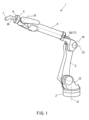
- the industrial robot 1 has a base 2 which is rotatable about a first axis (turn axis) J1, and a base end of a lower arm 3 is connected to this base 2 so as to be rotatable about a second axis J2.
- a base end of an upper arm 4 is connected to a distal end of the lower arm 3 so as to be rotatable about a third axis J3.
- the upper arm 4 is rotatable about its longitudinal axis (fourth axis) J4.
- a wrist portion 5 is connected to a distal end of the upper arm 4 so as to be swingable about a fifth axis (swing axis) J5.
- the fifth axis J5 is orthogonal to the longitudinal axis (fourth axis) J4 of the upper arm 4.
- a rotary body 6 which is rotatable about a center axis (sixth axis) J6 of the wrist portion 5 is provided to a distal end surface of the wrist portion 5.
- An end effector 7 such as a coating gun or a welding torch is mounted to the rotary body 6.
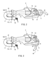
- a hollow part 8 which extends along the longitudinal axis J4 of the upper arm 4 is formed inside the upper arm 4.
- a plurality of wire bodies 9 as piping or wiring for supplying material and power to the end effector 7 are inserted through the hollow part 8 of the upper arm 4.
- a plurality of wire bodies 9 are covered by a tubular cover member 10 as a whole.
- Distal ends of a plurality of wire bodies 9 are connected to the end effector 7 such as a coating gun or a welding torch.
- a plurality of wire bodies 9 covered by the tubular cover member 10 have a curved portion (U-shaped portion) 11 in a part extending outward from a base end of the upper arm 4.
- a folded portion 11a of the curved portion 11 of a plurality of wire bodies 9 is fixed to the side of the base end of the upper arm 4 by a mounting member consisting of a bracket 12 and a clamp 13.
- the upper arm 4 has, on its distal end, an open space 14 which is opened in two directions orthogonal to both the longitudinal axis (fourth axis) J4 and the swing axis (fifth axis) J5. As is best illustrated in FIG. 3 , the open space 14 is also opened forward, and the wrist portion 5 is arranged utilizing the part opened forward.
- the open space 14 of the upper arm 4 is defined inside the upper arm 4 by a wall portion 15 which is provided on the opposite side of the wrist portion 5.
- a wall portion 15 which is provided on the opposite side of the wrist portion 5.
- an insertion hole 16 through which a plurality of wire bodies 9 covered by the tubular cover member 10 are inserted is formed.
- the open space 14 of the upper arm 4 is opened in two directions orthogonal to both the longitudinal axis (fourth axis) J4 and the swing axis (fifth axis) J5 in this example, the open space may be formed so as to be opened in one direction as a variation.
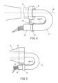
- the industrial robot has an energizing unit 17 for energizing a plurality of wire bodies 9 in a separate direction (rearward) away from the wrist portion 5 along the longitudinal axis J4 of the upper arm 4.
- the energizing unit 17 has a plate spring (elastic body) 18 for pulling a plurality of wire bodies 9 rearward.
- a base end of the plate spring (elastic body) 18 is fixed to the upper arm 4 via the mounting member consisting of the bracket 12 and the clamp 13.
- the plate spring 18 is elastically deformed and extended along the curved portion 11 of a plurality of wire bodies 9, and thereby the plate spring 18 applies energizing force to the curved portion 11 of the wire bodies 9.
- a plurality of wire bodies 9 extending inside the upper arm 4 are pulled rearward along the longitudinal axis J4 of the upper arm 4 at all times.
- the wire body 9 is smoothly displaced forward and rearward corresponding to the swing motion of the wrist portion 5 by energizing the wire body 9 rearward by the energizing unit 17 consisting of the plate spring 18 as mentioned above, and therefore the problems above in the conventional industrial robot are solved.
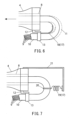
- a helical spring (elastic body) 19 may be used as illustrated in FIG. 7 instead of the plate spring 18 illustrated in FIG. 4 and FIG. 5 .
- One end of the helical spring 19 is fixed to the curved portion 11 of a plurality of wire bodies 9 via a ring member (mounting member) 20.
- the other end of the helical spring 19 is fixed to the upper arm 4 via a bracket (mounting member) 21.
- the helical spring 19 is in a pulled state at all times.
- all or part of a plurality of wire bodies 9 may respectively inserted through an elastic tubular member 22 having elasticity.
- the energizing unit 17 is configured so as to energize the wire body 9 utilizing the elastic force generated by the elasticity of the elastic tubular member 22.
- the curved portion 11 of the wire body 9 is inserted through the elastic tubular member 22, and the energizing unit 17 energizes the wire body 9 utilizing the elastic force generated in a part of the elastic tubular member 22 corresponding to the curved portion 11 of the wire body 9.
- the elastic tubular member 22 also can be utilized as a protective member for the wire body 9.
- the wire body 9 can be protected from sputter during welding, for example.
- FIG. 9 and FIG. 10 may be combined with the configuration in FIG. 4 and FIG. 5 or the configuration in FIG. 7 and FIG. 8 .
- a plurality of wire bodies 9 may be energized rearward by resultant force of the elastic force of a spring member such as the plate spring 18 or the helical spring 19 and the elastic force of the elastic tubular member 22.
Landscapes
- Engineering & Computer Science (AREA)
- Robotics (AREA)
- Mechanical Engineering (AREA)
- Manipulator (AREA)
Claims (4)
- Ein Industrieroboter (1), der Folgendes umfasst:einen Armabschnitt (4) mit einer Längsachse (J1);ein Handgelenkteil (5), das an einem distalen Ende des Armabschnitts (4) bereitgestellt wird und um eine zur Längsachse (J1) orthogonale Schwenkachse (J5) schwenkbar ist;eine Vielzahl von Drahtkörpern (9), die durch eine Innenseite des Armabschnitts (4) eingesetzt und mit einem Endeffektor (7) verbunden sind, der am Handgelenkabschnitt (5) montiert ist; undeine Erregungseinheit bzw. energiespendende Einheit (energizing unit) (17), die so konfiguriert ist, dass sie die Vielzahl von Drahtkörpern (9) in einer separaten Richtung weg vom Handgelenkabschnitt (5) entlang der Längsachse (J1) des Armabschnitts (4) mit Energie versorgt,wobei die Vielzahl von Drahtkörpern (9) jeweils durch eine Vielzahl von rohrförmigen Elementen (22) eingesetzt sind, wobei die Vielzahl von rohrförmigen Elementen (22) jeweils Elastizitäten aufweisen,dadurch gekennzeichnet, dassdie energiespendende Einheit (17) so konfiguriert ist, dass sie die Vielzahl von Drahtkörpern (9) unter Verwendung elastischer Kräfte mit Energie versorgt, die durch die Elastizitäten der Vielzahl von rohrförmigen Elementen (22) erzeugt werden,wobei die Vielzahl von Drahtkörpern (9) gekrümmte Abschnitte (11) in Teilen aufweisen, die sich jeweils ausgehend von einem Basisende des Armabschnitts (4) erstrecken,wobei die gekrümmten Abschnitte (11) der Vielzahl von Drahtkörpern (9) jeweils durch die Vielzahl von rohrförmigen Elementen (22) eingesetzt sind, undwobei die energiespendende Einheit (17) so konfiguriert ist, dass sie die Vielzahl von Drahtkörpern (9) unter Verwendung der elastischen Kräfte mit Energie versorgt, die in Teilen der Vielzahl von rohrförmigen Elementen (22) erzeugt werden, die den gekrümmten Abschnitten (11) der Vielzahl von Drahtkörpern (9) entsprechen.
- Der Industrieroboter nach Anspruch 1, der ferner ein rohrförmiges Abdeckelement (10) umfasst, das eine Gesamtheit der Vielzahl von Drahtkörpern (9) abdeckt,wobei die energiespendende Einheit (17) ferner einen elastischen Körper (18) aufweist, der eine Kraft erzeugt, die die Gesamtheit der Vielzahl von Drahtkörpern (9) in der separaten Richtung vorspannt,wobei der elastische Körper (18) ein Federelement (18) beinhaltet, dessen Teil am Armabschnitt (4) befestigt ist,wobei das Federelement (18) eine Blattfeder (18) beinhaltet, die sich entlang einer inneren Umfangsfläche eines Teils des rohrförmigen Abdeckelements (10) erstreckt, der den gekrümmten Abschnitten (11) entspricht, undwobei die energiespendende Einheit (17) so konfiguriert ist, dass sie die Vielzahl von Drahtkörpern (9) durch die elastischen Kräfte der Vielzahl von rohrförmigen Elementen (22) und eine elastische Kraft der Blattfeder (18) mit Energie versorgt.
- Der Industrieroboter nach Anspruch 1 oder 2, wobei der Armabschnitt (4) einen offenen Raum aufweist, der in Richtungen geöffnet ist, die sowohl zur Längsachse (J1) als auch zur Schwenkachse (J5) orthogonal sind.
- Der Industrieroboter nach Anspruch 3,wobei ein Teil des offenen Raums innerhalb des Armabschnitts (4) durch einen Wandabschnitt (15) definiert ist, der auf einer gegenüberliegenden Seite des Handgelenkabschnitts (5) bereitgestellt wird, undwobei ein Einführungsloch (16), durch das die Vielzahl von Drahtkörpern (9) eingesetzt wird, im Wandabschnitt (15) ausgebildet ist.
Applications Claiming Priority (2)
| Application Number | Priority Date | Filing Date | Title |
|---|---|---|---|
| JP2015009406A JP2016132076A (ja) | 2015-01-21 | 2015-01-21 | 産業用ロボット |
| PCT/JP2016/051388 WO2016117537A1 (ja) | 2015-01-21 | 2016-01-19 | 産業用ロボット |
Publications (3)
| Publication Number | Publication Date |
|---|---|
| EP3248739A1 EP3248739A1 (de) | 2017-11-29 |
| EP3248739A4 EP3248739A4 (de) | 2018-12-19 |
| EP3248739B1 true EP3248739B1 (de) | 2024-05-08 |
Family
ID=56417079
Family Applications (1)
| Application Number | Title | Priority Date | Filing Date |
|---|---|---|---|
| EP16740144.7A Active EP3248739B1 (de) | 2015-01-21 | 2016-01-19 | Industrieroboter |
Country Status (7)
| Country | Link |
|---|---|
| US (1) | US20180009117A1 (de) |
| EP (1) | EP3248739B1 (de) |
| JP (1) | JP2016132076A (de) |
| KR (1) | KR102092449B1 (de) |
| CN (1) | CN107249832B (de) |
| TW (1) | TWI606906B (de) |
| WO (1) | WO2016117537A1 (de) |
Families Citing this family (4)
| Publication number | Priority date | Publication date | Assignee | Title |
|---|---|---|---|---|
| JP6506342B2 (ja) * | 2017-04-26 | 2019-04-24 | 株式会社安川電機 | ロボット |
| JP6863397B2 (ja) * | 2019-03-27 | 2021-04-21 | 株式会社安川電機 | ロボット |
| JP7328442B2 (ja) * | 2020-03-26 | 2023-08-16 | ファナック株式会社 | ロボットの線条体処理構造 |
| JPWO2024201937A1 (de) * | 2023-03-30 | 2024-10-03 |
Family Cites Families (37)
| Publication number | Priority date | Publication date | Assignee | Title |
|---|---|---|---|---|
| US4076272A (en) * | 1975-06-23 | 1978-02-28 | Penton Hose Protection Systems, Inc. | Retractable conduit system |
| DE10224858B4 (de) * | 2002-06-05 | 2005-07-14 | Kuka Roboter Gmbh | Vorrichtung zum Führen eines Schlauches |
| JPS612727U (ja) * | 1984-06-08 | 1986-01-09 | 株式会社明電舎 | 伸縮部の配線構造 |
| JPS6411781A (en) * | 1987-07-06 | 1989-01-17 | Mitsubishi Electric Corp | Industrial robot |
| JPH02160498A (ja) * | 1988-12-13 | 1990-06-20 | Kobe Steel Ltd | 産業用ロボット |
| JPH05131388A (ja) * | 1991-11-07 | 1993-05-28 | Hitachi Ltd | 工業用ロボツトの手首装置 |
| JPH05329791A (ja) * | 1992-05-27 | 1993-12-14 | Yaskawa Electric Corp | 産業用ロボットの手首ユニット |
| JPH1034588A (ja) * | 1996-07-19 | 1998-02-10 | Toyoda Mach Works Ltd | 工業用ロボットの配線ケーブル支持装置 |
| SE511235C2 (sv) * | 1996-10-14 | 1999-08-30 | Asea Brown Boveri | Anordning och förfarande för att vid en manipulator hålla och föra ett kablage |
| JPH10217178A (ja) * | 1997-02-07 | 1998-08-18 | Honda Motor Co Ltd | ロボットにおけるケーブルの配線装置 |
| DE19817605A1 (de) * | 1998-04-17 | 1999-10-21 | Kuka Roboter Gmbh | Roboter mit zumindestens teilweise außenseitig verlaufenden Kabeln |
| JP2002008457A (ja) * | 2000-06-22 | 2002-01-11 | Toshiba Corp | 複合信号ケーブルとその取り付け方法 |
| JP2002283275A (ja) * | 2001-03-21 | 2002-10-03 | Fanuc Ltd | ロボットの手首構造 |
| JP4142304B2 (ja) * | 2001-10-22 | 2008-09-03 | 株式会社安川電機 | アーク溶接用ロボット |
| DE10158741A1 (de) * | 2001-11-30 | 2003-06-12 | Andries Broekhuijsen | Leitungsführungsvorrichtung |
| JP2004358649A (ja) * | 2003-05-12 | 2004-12-24 | Yaskawa Electric Corp | 産業用ロボット |
| JP4529456B2 (ja) * | 2003-11-28 | 2010-08-25 | 株式会社安川電機 | 産業用ロボットの腕機構 |
| JP4286684B2 (ja) * | 2004-02-27 | 2009-07-01 | 株式会社ダイヘン | アーク溶接ロボットにおけるケーブル配設構造 |
| DE102004019838C5 (de) * | 2004-04-23 | 2013-07-25 | Kuka Roboter Gmbh | Vorrichtung zum geführten Ein- und Ausfahren von Energieleitern |
| JP4168008B2 (ja) * | 2004-06-04 | 2008-10-22 | ファナック株式会社 | 産業用ロボットの線条体処理構造 |
| JP4038217B2 (ja) * | 2005-07-14 | 2008-01-23 | ファナック株式会社 | 産業用ロボットの線条体処理構造 |
| JP2007181268A (ja) * | 2005-12-27 | 2007-07-12 | Yazaki Corp | スライド構造体用の給電装置 |
| JP2007229874A (ja) * | 2006-03-01 | 2007-09-13 | Kawasaki Heavy Ind Ltd | 産業用ロボット |
| DE502006006292D1 (de) * | 2006-09-27 | 2010-04-08 | Leoni Protec Cable Systems Gmb | Gungsleitung aufweisenden schlauches |
| CN101309784B (zh) * | 2006-10-13 | 2010-06-09 | 松下电器产业株式会社 | 工业用机器人 |
| DE102007009850A1 (de) * | 2007-02-28 | 2008-09-04 | Kuka Roboter Gmbh | Roboterarm für einen Industrieroboter |
| JP2008238320A (ja) * | 2007-03-27 | 2008-10-09 | Fanuc Ltd | 作業ツールを備えたロボット |
| DE102007018543B4 (de) * | 2007-04-17 | 2009-02-26 | Philipp, Steffen | Vorrichtung zum Führen von Versorgungsleitungen entlang der Struktur eines Industrieroboters |
| JP4261598B2 (ja) * | 2007-07-30 | 2009-04-30 | ファナック株式会社 | 産業用ロボットの線条体処理構造 |
| DE102007056774A1 (de) * | 2007-11-23 | 2009-06-04 | Kuka Roboter Gmbh | Industrieroboter mit einem Arm zur Führung einer Leitungsanordnung |
| JP4658221B1 (ja) * | 2009-11-26 | 2011-03-23 | 株式会社椿本チエイン | 多関節型ケーブル類保護案内装置 |
| CN202029135U (zh) * | 2011-03-10 | 2011-11-09 | Abb技术公司 | 布线辅助机构和布线系统 |
| DE202011004786U1 (de) * | 2011-04-01 | 2011-07-08 | Igus Gmbh | Führungssystem für Versorgungsleitungen und Roboter mit Führungssystem |
| CN103056877B (zh) * | 2011-10-21 | 2015-07-29 | 鸿富锦精密工业(深圳)有限公司 | 机械手 |
| JP5346105B2 (ja) * | 2012-03-27 | 2013-11-20 | ファナック株式会社 | 線条体処理装置 |
| JP2014100743A (ja) * | 2012-11-16 | 2014-06-05 | Fanuc Ltd | 多関節ロボットのケーブル処理構造 |
| CN103085062B (zh) * | 2013-01-29 | 2015-02-25 | 东华大学 | 一种可用于机器人关节驱动的线管绳索传动系统 |
-
2015
- 2015-01-21 JP JP2015009406A patent/JP2016132076A/ja active Pending
-
2016
- 2016-01-19 KR KR1020177023106A patent/KR102092449B1/ko active Active
- 2016-01-19 EP EP16740144.7A patent/EP3248739B1/de active Active
- 2016-01-19 US US15/545,343 patent/US20180009117A1/en not_active Abandoned
- 2016-01-19 WO PCT/JP2016/051388 patent/WO2016117537A1/ja not_active Ceased
- 2016-01-19 CN CN201680006759.8A patent/CN107249832B/zh active Active
- 2016-01-21 TW TW105101915A patent/TWI606906B/zh active
Also Published As
| Publication number | Publication date |
|---|---|
| EP3248739A1 (de) | 2017-11-29 |
| JP2016132076A (ja) | 2016-07-25 |
| KR102092449B1 (ko) | 2020-03-23 |
| TWI606906B (zh) | 2017-12-01 |
| EP3248739A4 (de) | 2018-12-19 |
| TW201636172A (zh) | 2016-10-16 |
| KR20170108981A (ko) | 2017-09-27 |
| CN107249832A (zh) | 2017-10-13 |
| CN107249832B (zh) | 2022-06-14 |
| US20180009117A1 (en) | 2018-01-11 |
| WO2016117537A1 (ja) | 2016-07-28 |
Similar Documents
| Publication | Publication Date | Title |
|---|---|---|
| EP3064324B1 (de) | Roboter | |
| RU2539279C1 (ru) | Приспособление для автоматической подачи соединительных элементов к обрабатывающему устройству и подающий рукав для соединительных элементов | |
| JP4632181B2 (ja) | 産業用ロボット | |
| US5901756A (en) | Flexible wear sleeve | |
| US9197052B2 (en) | Umbilical member guide device at front end part of wrist of industrial robot and industrial robot | |
| EP1714751A2 (de) | Verformbare Struktur und Kabelstützsystem | |
| EP1666218B1 (de) | Führungsvorrichtung für die Versorgungsleitung eines Roboters und Roboter mit einer solchen Führungsvorrichtung | |
| EP3248739A1 (de) | Industrieroboter | |
| US20170252931A1 (en) | Cable-management system, a rotary joint and a robot | |
| JP7052430B2 (ja) | 紐状物結束具 | |
| US11141869B2 (en) | Robot-arm harness connection structure and multi-joined welding robot | |
| CN102781632B (zh) | 机器人手腕 | |
| WO1998019090A1 (en) | Cable assembly holder for an industrial robot | |
| JP5833901B2 (ja) | 多関節型産業用ロボット | |
| US20250091231A1 (en) | Wire body fixing structure, machine, robot, and actuator | |
| JP2019111627A (ja) | ロボットとその線条体処理構造 | |
| JP6994015B2 (ja) | 産業用ロボット | |
| JPH04269193A (ja) | 産業用ロボツト | |
| JP2016058291A (ja) | 環状弾性部品の拡張治具及び環状弾性部品付ワイヤーハーネスの製造方法 | |
| WO2016158279A1 (ja) | ロボットハンド及び関節ユニット | |
| JP2024039554A (ja) | ロボットハンド | |
| WO2023067812A1 (ja) | 被覆部材固定構造、機械、及びロボット | |
| CN211605941U (zh) | 用于约束线缆的卡簧、机器人关节和协作机器人 | |
| EP2999069A1 (de) | Montagehilfsanordnung und Verfahren zur Montage eines Roboterkabelbaums | |
| JP2024154306A (ja) | ロボット |
Legal Events
| Date | Code | Title | Description |
|---|---|---|---|
| STAA | Information on the status of an ep patent application or granted ep patent |
Free format text: STATUS: THE INTERNATIONAL PUBLICATION HAS BEEN MADE |
|
| PUAI | Public reference made under article 153(3) epc to a published international application that has entered the european phase |
Free format text: ORIGINAL CODE: 0009012 |
|
| STAA | Information on the status of an ep patent application or granted ep patent |
Free format text: STATUS: REQUEST FOR EXAMINATION WAS MADE |
|
| 17P | Request for examination filed |
Effective date: 20170821 |
|
| AK | Designated contracting states |
Kind code of ref document: A1 Designated state(s): AL AT BE BG CH CY CZ DE DK EE ES FI FR GB GR HR HU IE IS IT LI LT LU LV MC MK MT NL NO PL PT RO RS SE SI SK SM TR |
|
| AX | Request for extension of the european patent |
Extension state: BA ME |
|
| DAV | Request for validation of the european patent (deleted) | ||
| DAX | Request for extension of the european patent (deleted) | ||
| A4 | Supplementary search report drawn up and despatched |
Effective date: 20181121 |
|
| RIC1 | Information provided on ipc code assigned before grant |
Ipc: B25J 19/00 20060101AFI20181115BHEP |
|
| STAA | Information on the status of an ep patent application or granted ep patent |
Free format text: STATUS: EXAMINATION IS IN PROGRESS |
|
| 17Q | First examination report despatched |
Effective date: 20220315 |
|
| GRAP | Despatch of communication of intention to grant a patent |
Free format text: ORIGINAL CODE: EPIDOSNIGR1 |
|
| STAA | Information on the status of an ep patent application or granted ep patent |
Free format text: STATUS: GRANT OF PATENT IS INTENDED |
|
| INTG | Intention to grant announced |
Effective date: 20231208 |
|
| GRAS | Grant fee paid |
Free format text: ORIGINAL CODE: EPIDOSNIGR3 |
|
| GRAA | (expected) grant |
Free format text: ORIGINAL CODE: 0009210 |
|
| STAA | Information on the status of an ep patent application or granted ep patent |
Free format text: STATUS: THE PATENT HAS BEEN GRANTED |
|
| AK | Designated contracting states |
Kind code of ref document: B1 Designated state(s): AL AT BE BG CH CY CZ DE DK EE ES FI FR GB GR HR HU IE IS IT LI LT LU LV MC MK MT NL NO PL PT RO RS SE SI SK SM TR |
|
| REG | Reference to a national code |
Ref country code: GB Ref legal event code: FG4D |
|
| REG | Reference to a national code |
Ref country code: CH Ref legal event code: EP |
|
| REG | Reference to a national code |
Ref country code: DE Ref legal event code: R096 Ref document number: 602016087418 Country of ref document: DE |
|
| REG | Reference to a national code |
Ref country code: IE Ref legal event code: FG4D |
|
| REG | Reference to a national code |
Ref country code: LT Ref legal event code: MG9D |
|
| REG | Reference to a national code |
Ref country code: NL Ref legal event code: MP Effective date: 20240508 |
|
| PG25 | Lapsed in a contracting state [announced via postgrant information from national office to epo] |
Ref country code: IS Free format text: LAPSE BECAUSE OF FAILURE TO SUBMIT A TRANSLATION OF THE DESCRIPTION OR TO PAY THE FEE WITHIN THE PRESCRIBED TIME-LIMIT Effective date: 20240908 |
|
| PG25 | Lapsed in a contracting state [announced via postgrant information from national office to epo] |
Ref country code: BG Free format text: LAPSE BECAUSE OF FAILURE TO SUBMIT A TRANSLATION OF THE DESCRIPTION OR TO PAY THE FEE WITHIN THE PRESCRIBED TIME-LIMIT Effective date: 20240508 |
|
| PG25 | Lapsed in a contracting state [announced via postgrant information from national office to epo] |
Ref country code: FI Free format text: LAPSE BECAUSE OF FAILURE TO SUBMIT A TRANSLATION OF THE DESCRIPTION OR TO PAY THE FEE WITHIN THE PRESCRIBED TIME-LIMIT Effective date: 20240508 Ref country code: HR Free format text: LAPSE BECAUSE OF FAILURE TO SUBMIT A TRANSLATION OF THE DESCRIPTION OR TO PAY THE FEE WITHIN THE PRESCRIBED TIME-LIMIT Effective date: 20240508 |
|
| PG25 | Lapsed in a contracting state [announced via postgrant information from national office to epo] |
Ref country code: GR Free format text: LAPSE BECAUSE OF FAILURE TO SUBMIT A TRANSLATION OF THE DESCRIPTION OR TO PAY THE FEE WITHIN THE PRESCRIBED TIME-LIMIT Effective date: 20240809 |
|
| PG25 | Lapsed in a contracting state [announced via postgrant information from national office to epo] |
Ref country code: PT Free format text: LAPSE BECAUSE OF FAILURE TO SUBMIT A TRANSLATION OF THE DESCRIPTION OR TO PAY THE FEE WITHIN THE PRESCRIBED TIME-LIMIT Effective date: 20240909 |
|
| REG | Reference to a national code |
Ref country code: AT Ref legal event code: MK05 Ref document number: 1684626 Country of ref document: AT Kind code of ref document: T Effective date: 20240508 |
|
| PG25 | Lapsed in a contracting state [announced via postgrant information from national office to epo] |
Ref country code: NL Free format text: LAPSE BECAUSE OF FAILURE TO SUBMIT A TRANSLATION OF THE DESCRIPTION OR TO PAY THE FEE WITHIN THE PRESCRIBED TIME-LIMIT Effective date: 20240508 |
|
| PG25 | Lapsed in a contracting state [announced via postgrant information from national office to epo] |
Ref country code: ES Free format text: LAPSE BECAUSE OF FAILURE TO SUBMIT A TRANSLATION OF THE DESCRIPTION OR TO PAY THE FEE WITHIN THE PRESCRIBED TIME-LIMIT Effective date: 20240508 |
|
| PG25 | Lapsed in a contracting state [announced via postgrant information from national office to epo] |
Ref country code: AT Free format text: LAPSE BECAUSE OF FAILURE TO SUBMIT A TRANSLATION OF THE DESCRIPTION OR TO PAY THE FEE WITHIN THE PRESCRIBED TIME-LIMIT Effective date: 20240508 |
|
| PG25 | Lapsed in a contracting state [announced via postgrant information from national office to epo] |
Ref country code: PL Free format text: LAPSE BECAUSE OF FAILURE TO SUBMIT A TRANSLATION OF THE DESCRIPTION OR TO PAY THE FEE WITHIN THE PRESCRIBED TIME-LIMIT Effective date: 20240508 |
|
| PG25 | Lapsed in a contracting state [announced via postgrant information from national office to epo] |
Ref country code: LV Free format text: LAPSE BECAUSE OF FAILURE TO SUBMIT A TRANSLATION OF THE DESCRIPTION OR TO PAY THE FEE WITHIN THE PRESCRIBED TIME-LIMIT Effective date: 20240508 |
|
| PG25 | Lapsed in a contracting state [announced via postgrant information from national office to epo] |
Ref country code: PT Free format text: LAPSE BECAUSE OF FAILURE TO SUBMIT A TRANSLATION OF THE DESCRIPTION OR TO PAY THE FEE WITHIN THE PRESCRIBED TIME-LIMIT Effective date: 20240909 Ref country code: PL Free format text: LAPSE BECAUSE OF FAILURE TO SUBMIT A TRANSLATION OF THE DESCRIPTION OR TO PAY THE FEE WITHIN THE PRESCRIBED TIME-LIMIT Effective date: 20240508 Ref country code: NO Free format text: LAPSE BECAUSE OF FAILURE TO SUBMIT A TRANSLATION OF THE DESCRIPTION OR TO PAY THE FEE WITHIN THE PRESCRIBED TIME-LIMIT Effective date: 20240808 Ref country code: NL Free format text: LAPSE BECAUSE OF FAILURE TO SUBMIT A TRANSLATION OF THE DESCRIPTION OR TO PAY THE FEE WITHIN THE PRESCRIBED TIME-LIMIT Effective date: 20240508 Ref country code: LV Free format text: LAPSE BECAUSE OF FAILURE TO SUBMIT A TRANSLATION OF THE DESCRIPTION OR TO PAY THE FEE WITHIN THE PRESCRIBED TIME-LIMIT Effective date: 20240508 Ref country code: IS Free format text: LAPSE BECAUSE OF FAILURE TO SUBMIT A TRANSLATION OF THE DESCRIPTION OR TO PAY THE FEE WITHIN THE PRESCRIBED TIME-LIMIT Effective date: 20240908 Ref country code: HR Free format text: LAPSE BECAUSE OF FAILURE TO SUBMIT A TRANSLATION OF THE DESCRIPTION OR TO PAY THE FEE WITHIN THE PRESCRIBED TIME-LIMIT Effective date: 20240508 Ref country code: GR Free format text: LAPSE BECAUSE OF FAILURE TO SUBMIT A TRANSLATION OF THE DESCRIPTION OR TO PAY THE FEE WITHIN THE PRESCRIBED TIME-LIMIT Effective date: 20240809 Ref country code: FI Free format text: LAPSE BECAUSE OF FAILURE TO SUBMIT A TRANSLATION OF THE DESCRIPTION OR TO PAY THE FEE WITHIN THE PRESCRIBED TIME-LIMIT Effective date: 20240508 Ref country code: ES Free format text: LAPSE BECAUSE OF FAILURE TO SUBMIT A TRANSLATION OF THE DESCRIPTION OR TO PAY THE FEE WITHIN THE PRESCRIBED TIME-LIMIT Effective date: 20240508 Ref country code: BG Free format text: LAPSE BECAUSE OF FAILURE TO SUBMIT A TRANSLATION OF THE DESCRIPTION OR TO PAY THE FEE WITHIN THE PRESCRIBED TIME-LIMIT Effective date: 20240508 Ref country code: AT Free format text: LAPSE BECAUSE OF FAILURE TO SUBMIT A TRANSLATION OF THE DESCRIPTION OR TO PAY THE FEE WITHIN THE PRESCRIBED TIME-LIMIT Effective date: 20240508 Ref country code: RS Free format text: LAPSE BECAUSE OF FAILURE TO SUBMIT A TRANSLATION OF THE DESCRIPTION OR TO PAY THE FEE WITHIN THE PRESCRIBED TIME-LIMIT Effective date: 20240808 |
|
| PG25 | Lapsed in a contracting state [announced via postgrant information from national office to epo] |
Ref country code: DK Free format text: LAPSE BECAUSE OF FAILURE TO SUBMIT A TRANSLATION OF THE DESCRIPTION OR TO PAY THE FEE WITHIN THE PRESCRIBED TIME-LIMIT Effective date: 20240508 |
|
| PG25 | Lapsed in a contracting state [announced via postgrant information from national office to epo] |
Ref country code: EE Free format text: LAPSE BECAUSE OF FAILURE TO SUBMIT A TRANSLATION OF THE DESCRIPTION OR TO PAY THE FEE WITHIN THE PRESCRIBED TIME-LIMIT Effective date: 20240508 |
|
| PG25 | Lapsed in a contracting state [announced via postgrant information from national office to epo] |
Ref country code: CZ Free format text: LAPSE BECAUSE OF FAILURE TO SUBMIT A TRANSLATION OF THE DESCRIPTION OR TO PAY THE FEE WITHIN THE PRESCRIBED TIME-LIMIT Effective date: 20240508 |
|
| PG25 | Lapsed in a contracting state [announced via postgrant information from national office to epo] |
Ref country code: SK Free format text: LAPSE BECAUSE OF FAILURE TO SUBMIT A TRANSLATION OF THE DESCRIPTION OR TO PAY THE FEE WITHIN THE PRESCRIBED TIME-LIMIT Effective date: 20240508 Ref country code: RO Free format text: LAPSE BECAUSE OF FAILURE TO SUBMIT A TRANSLATION OF THE DESCRIPTION OR TO PAY THE FEE WITHIN THE PRESCRIBED TIME-LIMIT Effective date: 20240508 |
|
| PG25 | Lapsed in a contracting state [announced via postgrant information from national office to epo] |
Ref country code: SM Free format text: LAPSE BECAUSE OF FAILURE TO SUBMIT A TRANSLATION OF THE DESCRIPTION OR TO PAY THE FEE WITHIN THE PRESCRIBED TIME-LIMIT Effective date: 20240508 |
|
| PG25 | Lapsed in a contracting state [announced via postgrant information from national office to epo] |
Ref country code: SM Free format text: LAPSE BECAUSE OF FAILURE TO SUBMIT A TRANSLATION OF THE DESCRIPTION OR TO PAY THE FEE WITHIN THE PRESCRIBED TIME-LIMIT Effective date: 20240508 Ref country code: SK Free format text: LAPSE BECAUSE OF FAILURE TO SUBMIT A TRANSLATION OF THE DESCRIPTION OR TO PAY THE FEE WITHIN THE PRESCRIBED TIME-LIMIT Effective date: 20240508 Ref country code: RO Free format text: LAPSE BECAUSE OF FAILURE TO SUBMIT A TRANSLATION OF THE DESCRIPTION OR TO PAY THE FEE WITHIN THE PRESCRIBED TIME-LIMIT Effective date: 20240508 Ref country code: EE Free format text: LAPSE BECAUSE OF FAILURE TO SUBMIT A TRANSLATION OF THE DESCRIPTION OR TO PAY THE FEE WITHIN THE PRESCRIBED TIME-LIMIT Effective date: 20240508 Ref country code: DK Free format text: LAPSE BECAUSE OF FAILURE TO SUBMIT A TRANSLATION OF THE DESCRIPTION OR TO PAY THE FEE WITHIN THE PRESCRIBED TIME-LIMIT Effective date: 20240508 Ref country code: CZ Free format text: LAPSE BECAUSE OF FAILURE TO SUBMIT A TRANSLATION OF THE DESCRIPTION OR TO PAY THE FEE WITHIN THE PRESCRIBED TIME-LIMIT Effective date: 20240508 |
|
| PG25 | Lapsed in a contracting state [announced via postgrant information from national office to epo] |
Ref country code: IT Free format text: LAPSE BECAUSE OF FAILURE TO SUBMIT A TRANSLATION OF THE DESCRIPTION OR TO PAY THE FEE WITHIN THE PRESCRIBED TIME-LIMIT Effective date: 20240508 |
|
| REG | Reference to a national code |
Ref country code: DE Ref legal event code: R097 Ref document number: 602016087418 Country of ref document: DE |
|
| PLBE | No opposition filed within time limit |
Free format text: ORIGINAL CODE: 0009261 |
|
| STAA | Information on the status of an ep patent application or granted ep patent |
Free format text: STATUS: NO OPPOSITION FILED WITHIN TIME LIMIT |
|
| 26N | No opposition filed |
Effective date: 20250211 |
|
| PG25 | Lapsed in a contracting state [announced via postgrant information from national office to epo] |
Ref country code: SI Free format text: LAPSE BECAUSE OF FAILURE TO SUBMIT A TRANSLATION OF THE DESCRIPTION OR TO PAY THE FEE WITHIN THE PRESCRIBED TIME-LIMIT Effective date: 20240508 |
|
| REG | Reference to a national code |
Ref country code: CH Ref legal event code: PL |
|
| PG25 | Lapsed in a contracting state [announced via postgrant information from national office to epo] |
Ref country code: SE Free format text: LAPSE BECAUSE OF FAILURE TO SUBMIT A TRANSLATION OF THE DESCRIPTION OR TO PAY THE FEE WITHIN THE PRESCRIBED TIME-LIMIT Effective date: 20240508 |
|
| PG25 | Lapsed in a contracting state [announced via postgrant information from national office to epo] |
Ref country code: MC Free format text: LAPSE BECAUSE OF FAILURE TO SUBMIT A TRANSLATION OF THE DESCRIPTION OR TO PAY THE FEE WITHIN THE PRESCRIBED TIME-LIMIT Effective date: 20240508 Ref country code: LU Free format text: LAPSE BECAUSE OF NON-PAYMENT OF DUE FEES Effective date: 20250119 |
|
| GBPC | Gb: european patent ceased through non-payment of renewal fee |
Effective date: 20250119 |
|
| PG25 | Lapsed in a contracting state [announced via postgrant information from national office to epo] |
Ref country code: GB Free format text: LAPSE BECAUSE OF NON-PAYMENT OF DUE FEES Effective date: 20250119 Ref country code: BE Free format text: LAPSE BECAUSE OF NON-PAYMENT OF DUE FEES Effective date: 20250131 |
|
| PG25 | Lapsed in a contracting state [announced via postgrant information from national office to epo] |
Ref country code: FR Free format text: LAPSE BECAUSE OF NON-PAYMENT OF DUE FEES Effective date: 20250131 |
|
| PG25 | Lapsed in a contracting state [announced via postgrant information from national office to epo] |
Ref country code: CH Free format text: LAPSE BECAUSE OF NON-PAYMENT OF DUE FEES Effective date: 20250131 |
|
| REG | Reference to a national code |
Ref country code: BE Ref legal event code: MM Effective date: 20250131 |
|
| PG25 | Lapsed in a contracting state [announced via postgrant information from national office to epo] |
Ref country code: IE Free format text: LAPSE BECAUSE OF NON-PAYMENT OF DUE FEES Effective date: 20250119 |
|
| PGFP | Annual fee paid to national office [announced via postgrant information from national office to epo] |
Ref country code: DE Payment date: 20251203 Year of fee payment: 11 |