EP3249108A1 - Charrue de remblayage - Google Patents
Charrue de remblayage Download PDFInfo
- Publication number
- EP3249108A1 EP3249108A1 EP17180897.5A EP17180897A EP3249108A1 EP 3249108 A1 EP3249108 A1 EP 3249108A1 EP 17180897 A EP17180897 A EP 17180897A EP 3249108 A1 EP3249108 A1 EP 3249108A1
- Authority
- EP
- European Patent Office
- Prior art keywords
- plow
- skid
- chassis
- trench
- moldboards
- Prior art date
- Legal status (The legal status is an assumption and is not a legal conclusion. Google has not performed a legal analysis and makes no representation as to the accuracy of the status listed.)
- Granted
Links
- 230000007704 transition Effects 0.000 claims description 77
- 238000005520 cutting process Methods 0.000 description 41
- 238000000034 method Methods 0.000 description 33
- 238000011084 recovery Methods 0.000 description 8
- 230000008569 process Effects 0.000 description 4
- 239000013535 sea water Substances 0.000 description 3
- 230000003466 anti-cipated effect Effects 0.000 description 2
- 239000012634 fragment Substances 0.000 description 2
- 238000012986 modification Methods 0.000 description 2
- 230000004048 modification Effects 0.000 description 2
- 238000011017 operating method Methods 0.000 description 2
- XLYOFNOQVPJJNP-UHFFFAOYSA-N water Substances O XLYOFNOQVPJJNP-UHFFFAOYSA-N 0.000 description 2
- 229910000831 Steel Inorganic materials 0.000 description 1
- 230000009471 action Effects 0.000 description 1
- 238000009933 burial Methods 0.000 description 1
- 230000000295 complement effect Effects 0.000 description 1
- 238000010276 construction Methods 0.000 description 1
- 238000007599 discharging Methods 0.000 description 1
- 238000009826 distribution Methods 0.000 description 1
- 230000005484 gravity Effects 0.000 description 1
- 230000006872 improvement Effects 0.000 description 1
- 238000005304 joining Methods 0.000 description 1
- 238000005259 measurement Methods 0.000 description 1
- 230000007246 mechanism Effects 0.000 description 1
- 239000000203 mixture Substances 0.000 description 1
- 230000035515 penetration Effects 0.000 description 1
- 238000002360 preparation method Methods 0.000 description 1
- 230000000284 resting effect Effects 0.000 description 1
- 239000010959 steel Substances 0.000 description 1
- 239000003351 stiffener Substances 0.000 description 1
- 238000003860 storage Methods 0.000 description 1
Images


Classifications
-
- E—FIXED CONSTRUCTIONS
- E02—HYDRAULIC ENGINEERING; FOUNDATIONS; SOIL SHIFTING
- E02F—DREDGING; SOIL-SHIFTING
- E02F5/00—Dredgers or soil-shifting machines for special purposes
- E02F5/02—Dredgers or soil-shifting machines for special purposes for digging trenches or ditches
- E02F5/027—Dredgers or soil-shifting machines for special purposes for digging trenches or ditches with coulters, ploughs, scraper plates, or the like
-
- E—FIXED CONSTRUCTIONS
- E02—HYDRAULIC ENGINEERING; FOUNDATIONS; SOIL SHIFTING
- E02F—DREDGING; SOIL-SHIFTING
- E02F5/00—Dredgers or soil-shifting machines for special purposes
- E02F5/02—Dredgers or soil-shifting machines for special purposes for digging trenches or ditches
- E02F5/10—Dredgers or soil-shifting machines for special purposes for digging trenches or ditches with arrangements for reinforcing trenches or ditches; with arrangements for making or assembling conduits or for laying conduits or cables
- E02F5/104—Dredgers or soil-shifting machines for special purposes for digging trenches or ditches with arrangements for reinforcing trenches or ditches; with arrangements for making or assembling conduits or for laying conduits or cables for burying conduits or cables in trenches under water
- E02F5/106—Dredgers or soil-shifting machines for special purposes for digging trenches or ditches with arrangements for reinforcing trenches or ditches; with arrangements for making or assembling conduits or for laying conduits or cables for burying conduits or cables in trenches under water using ploughs, coulters, rippers
-
- E—FIXED CONSTRUCTIONS
- E02—HYDRAULIC ENGINEERING; FOUNDATIONS; SOIL SHIFTING
- E02F—DREDGING; SOIL-SHIFTING
- E02F5/00—Dredgers or soil-shifting machines for special purposes
- E02F5/02—Dredgers or soil-shifting machines for special purposes for digging trenches or ditches
- E02F5/12—Dredgers or soil-shifting machines for special purposes for digging trenches or ditches with equipment for back-filling trenches or ditches
- E02F5/125—Dredgers or soil-shifting machines for special purposes for digging trenches or ditches with equipment for back-filling trenches or ditches underwater
-
- E—FIXED CONSTRUCTIONS
- E02—HYDRAULIC ENGINEERING; FOUNDATIONS; SOIL SHIFTING
- E02F—DREDGING; SOIL-SHIFTING
- E02F5/00—Dredgers or soil-shifting machines for special purposes
- E02F5/02—Dredgers or soil-shifting machines for special purposes for digging trenches or ditches
- E02F5/14—Component parts for trench excavators, e.g. indicating devices travelling gear chassis, supports, skids
-
- H—ELECTRICITY
- H02—GENERATION; CONVERSION OR DISTRIBUTION OF ELECTRIC POWER
- H02G—INSTALLATION OF ELECTRIC CABLES OR LINES, OR OF COMBINED OPTICAL AND ELECTRIC CABLES OR LINES
- H02G1/00—Methods or apparatus specially adapted for installing, maintaining, repairing or dismantling electric cables or lines
- H02G1/06—Methods or apparatus specially adapted for installing, maintaining, repairing or dismantling electric cables or lines for laying cables, e.g. laying apparatus on vehicle
- H02G1/10—Methods or apparatus specially adapted for installing, maintaining, repairing or dismantling electric cables or lines for laying cables, e.g. laying apparatus on vehicle in or under water
-
- B—PERFORMING OPERATIONS; TRANSPORTING
- B63—SHIPS OR OTHER WATERBORNE VESSELS; RELATED EQUIPMENT
- B63B—SHIPS OR OTHER WATERBORNE VESSELS; EQUIPMENT FOR SHIPPING
- B63B27/00—Arrangement of ship-based loading or unloading equipment for cargo or passengers
- B63B27/16—Arrangement of ship-based loading or unloading equipment for cargo or passengers of lifts or hoists
- B63B2027/165—Deployment or recovery of underwater vehicles using lifts or hoists
Definitions
- This invention relates generally to the offshore laying of pipe and cable and more particularly concerns equipment used in the preparation and trenching of the seabed to receive the pipe or cable and in the backfilling of the trench once the pipe or cable has been laid.
- Present pipe laying methods include a few basic seabed trenching tasks performed using long-accepted, time-consuming, budget-eating practices and equipment.
- boulders on, or partially buried in, the intended pipeline path One problem is that sometimes, before trenching can begin, it may be necessary to clear the seabed of boulders on, or partially buried in, the intended pipeline path.
- boulder removal process involves dragging the boulders, one at a time, at cables-end from a transport/towing vessel. In some boulder fields, this can be a lengthy and tedious process. It always requires one or more divers, a remotely operated vehicle (ROV), or other boulder handling mechanisms to connect the cable to the boulder.
- ROV remotely operated vehicle
- a trench cutting plow When the time for trench cutting arrives, a trench cutting plow must be lowered to the seabed.
- Launching a trench cutting plow typically requires a large vessel carrying a crane and supporting equipment to lift the plow from the vessel, to swing the plow clear of the deck and to lower the plow into the sea.
- retrieval of the trench cutting plow from the seabed to its storage area on the towing vessel again requires use of the crane and supporting equipment.
- known trench cutting plows In operation on the seabed, known trench cutting plows have additional problems. For example, many require skids which straddle the width of the trench being cut, so the number of possible passes that can be made and the depth of the trench that can be cut is limited.
- United Kingdom Patent Publication No. GB2285821A is directed specifically to trenching plows and more particularly to a trenching plow capable of digging trenches of significant depth, for example of the order of three meters.
- the publication acknowledges that a trenching plow for this purpose would require such great size and weight that a large force would be required to pull it through the ground and also that existing suggestions to use smaller plows in multiple passes had proven to be impracticable. Therefore, the disclosed plow was provided with adjustable-height supports or skids straddling the trench followed by one or two shares and one or two moldboards arranged in asymmetric or symmetric configurations intended to be used in at least two trenching passes to dig a subsea trench. The disclosure did not address the launch and retrieval problems associated with trenching plows.
- Typical known backfill plows have chasses with front skids which travel in the trench and straddle the pipeline, followed by moldboards which are angled forwardly and away from the chassis to collect the spoil in their path and deposit it in the trench to the sides of the pipeline.
- EP0116410 is directed specifically to a trench backfill device with a means for positioning the device centrally in the trench, such as wheels or skids angled to run on the sloping sides of a trench.
- United States Patent No. 3540226 is directed to a method of towing a vessel, such as a barge, on a body of water.
- the method requires the use of a uniquely designed trenching plow, a guiding means attached to the trenching plow for aligning the pipe with the trench, a novel method of pulling the trenching apparatus, and a backfiller in the trench with the pipe.
- Much of the seabed trenching task equipment and operating methods are, in terms of time and money, very inefficient and beg for improvement. But the inadequacy of the individual plows and their operating methods is dwarfed by the need for a large, heavily equipped vessel to transport, launch and retrieve these plows instead of a much smaller vessel which could otherwise be used for operating purposes.
- the cost of known trench cutting and backfill plows is in a range of $8,000,000 each.
- the cost of the transport/towing vessel with the crane and supporting equipment is in a range of $500,000,000.
- the rental fee for the vessel and plows ranges from $150,000 to $600,000 per day.
- a seabed-plow chassis in which an elongated member is adapted for mounting a skid on one of its ends to support that end above the seabed and is adapted for mounting one or more tools on its other end to perform a variety of seabed trenching tasks.
- the tool In a first mode of operation in which the chassis is a part of a boulder clearing plow, the tool consists of moldboards for clearing boulders which are initially pushed by the skid outward of the path traveled by the skid further outward from the path as the skid leads the moldboards along the seabed.
- the tool In a second mode of operation in which the chassis is a part of a trench cutting plow, the tool consists of a plow share and moldboards for sequentially cutting and moving spoil to create a trench as the skid leads the plow share and moldboards along the seabed.
- the tool In a third mode of operation in which the chassis is a part of a backfill plow, the tool consists of a blade and moldboards which cooperate as the blade and moldboards lead the skid along the seabed to sequentially collect, funnel inward and release downward into the trench spoil lying outside of the trench.
- Different chasses can be adapted to accommodate each of the modes or the same chassis can be adapted to interconnect any of the tools with the skid according to the desired mode of operation.
- the elongated member of the chassis may have one or more permanent transition surfaces or one or more attachments providing transition surfaces.
- the transition surfaces are configured to extend between the skid and the various tools which may be mounted on the chassis.
- the transition surface contours are shaped and located so that the appropriate transition surface makes contact with and pivots about a fulcrum on the stern of a plow transporting/towing vessel as the plow crosses that fulcrum during its release from the vessel into the sea and during its retrieval from the sea onto the vessel.
- the shapes and locations of the transition surfaces and the weight of the elongated member are coordinated so as to resist roll of the chassis about a transition axis as the plow moves on the deck or across the fulcrum.
- the vertical longitudinal cross-sections of the transition surfaces are concave
- the fulcrum is a roller
- the paths defined by continuous symmetrically opposite points of the transition surfaces are contoured to maintain contact with the roller as the plow crosses the roller.
- a first transition surface is configured to extend between the skid and the tool in the first/boulder clearing and third/backfill modes and a second transition surface is configured to extend between the skid and the tool in the second/trench cutting mode.
- the plow For clearing boulders from a seabed, the plow includes the chassis, a skid mounted on and supporting one end of the chassis above the seabed and moldboards mounted on and oriented in angular relationship to the other end of the chassis.
- the trailing moldboards clear boulders initially pushed outwardly by the leading skid further outward as the skid leads the moldboards along the seabed.
- a head is mounted on a leading end of the skid.
- the head has leading faces angled rearward from a vertical, longitudinal center plane of the skid and tapered rearward from its top edges, enabling the head to torque boulders partially buried in the seabed away from the skid.
- the chassis transition surface extends between the skid and the moldboards and is contoured to maintain contact with and pivot about the fulcrum/roller on the stern of the vessel as the plow crosses the fulcrum during launch and recovery.
- the boulder clearing plow may also include keel plates, at least one keel plate extending under each moldboard.
- the keel plates' primary function is to ensure the lateral stability of the plow during operation by resisting departure of the plow from its intended path even when the plow encounters seabed obstructions or uneven amounts of spoil.
- the plow components are, in weight and in their contact surfaces with the fulcrum, coordinated to resist roll of the plow about a launch and recovery transition axis of the boulder clearing plow.
- Pulling points for connection of a pulling line to the boulder clearing plow are symmetrically arranged in relation to the longitudinal axis of the chassis and are displaced from the bottom of the boulder clearing plow by a height less than a radius of the vessel roller to facilitate passage of the plow contact surface over the vessel roller.
- the method of clearing boulders from a path on the seabed includes the steps of positioning the plow bow-forward in the direction of an initial seabed path and then propelling the plow along the initial seabed path to push boulders lying in the initial seabed path to the port and starboard sides of the plow. After the initial path is cleared the method continues, if a wider path is necessary, with the step of repositioning the plow bow-forward in a direction opposite the initial seabed path direction and on a second seabed path along one of the port and starboard sides of the initial seabed path.
- the method continues with the step of propelling the plow along the second seabed path to push boulders from the second seabed path further to one of the starboard and port sides of the plow, respectively.
- the method continues, if an even wider path is necessary, with the step of repositioning the plow bow-forward in the direction of the initial seabed path and on a third seabed path along the other of the starboard and port sides of the initial seabed path.
- the method continues with the step of propelling the plow along the third seabed path to push boulders from the third seabed path further to the other of the starboard and port sides of the plow, respectively.
- the method can further include repeating the above widening steps in relation to the path resulting from the contiguity of the initial, second and third paths.
- the method anticipates repeating these steps for successively contiguous paths until a single path of desired width has been cleared along the seabed.
- the method of clearing boulders from the seabed path is preceded by the steps of propelling the plow on the deck of the vessel toward and across the fulcrum on the stern of the vessel, allowing the plow to rotate about the fulcrum as the plow crosses the fulcrum and is released from the fulcrum into the sea and lowering the released plow at tow-line end toward the seabed.
- the method of clearing boulders from the seabed path is followed by the steps of raising the plow at tow-line end toward the fulcrum on the stern of the vessel at the other end of the tow line and pulling the plow across the fulcrum onto the deck of the vessel.
- the plow For backfilling spoil into a seabed trench, the plow includes the chassis, a skid supporting the aft end of the chassis above the seabed, moldboards mounted on the chassis forward of the skid and a blade mounted on and spanning the bottom edges of the moldboards.
- the blade collects the spoil in its path as the plow travels forward on the seabed.
- the moldboards are sized and oriented to span the trench and funnel the collected spoil toward the center of the blade as the plow travels forward on the seabed.
- the blade has a passage at its rear apex which is configured to dispense the collected and funneled spoil onto the top of a pipe disposed in the trench below the passage.
- the backfill plow further includes a flapper board aft of the passage which fragments spoil discharged through the passage.
- the flapper board consists of a plate swinging below a horizontal shaft with a weight biasing the plate toward a vertical orientation.
- the skid is configured to straddle the trench and includes a crossbar mounted on the rear end of the chassis, a pair of skid posts, one on each end of the crossbar, and a pair of skis, one on the bottom of each post.
- the front surface of the crossbar may be adapted to the level spoil which has been discharged into the trench.
- the backfill plow may also include at least two keel plates spaced apart under the blade.
- the primary function of the keel plates is to ensure the lateral stability of the plow during operation by resisting departure of the backfill plow from its intended path even when the plow encounters seabed obstructions or uneven amounts of spoil.
- the plow has at least one transition surface between the skid and the moldboards which is contoured to contact and pivot about the fulcrum on the stern of a vessel as the backfill plow crosses the fulcrum during launch and retrieval of the backfill plow from and to the vessel.
- the plow components are, in weight and in contact surfaces with the fulcrum, coordinated to resist roll of the backfill plow about the transition axis of the plow.
- Pulling points for connection of a pulling line to the backfill plow are symmetrically arranged in relation to the longitudinal axis of the chassis and are displaced from the bottom of the backfill plow by a height less than the radius of the roller to facilitate passage of the plow contact surfaces over the roller.
- the method of backfilling spoil into a seabed trench includes the steps of propelling the blade to travel forward on the seabed and collect spoil along the sides of the trench, funneling the collected spoil toward a rear apex of the blade and allowing the funneled spoil to be discharged through an opening in the blade apex and onto a top surface of a pipe disposed in the trench.
- the method may further include one or both of the steps of fragmenting the discharged spoil before the discharged spoil reaches the pipe and/or leveling the spoil after it is discharged into the trench.
- the method of backfilling spoil into the trench is preceded by the steps of propelling the backfill plow on the deck of the vessel toward and across the fulcrum on the stern of the vessel, allowing the backfill plow to rotate about the fulcrum as the plow crosses the fulcrum and is released from the fulcrum into the sea and lowering the released plow at tow-line end to the seabed.
- the method of backfilling spoil into the trench can be followed by the steps of raising the backfill plow at tow-line end toward the fulcrum on the stern of the vessel at the other end of the tow line and pulling the plow across the fulcrum onto the deck of the vessel.
- the vessels needed for transport, launch, recovery and operation of the plows are smaller and presently plentiful. They are available to the user at rental fees ranging from $ 10,000 to $ 100,000 per day. This is a huge savings in comparison to the $ 150,000 to $600,000 per day rental fees presently paid for vessels required by the old plow structures and methods.
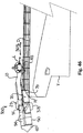
- a seabed-plow chassis 10 for use as a component of various seabed plows has an elongated member 11 adapted for mounting a skid on one of its ends 13 and one or more tools on its other end 15.
- the chassis 10 is used in a first mode of operation as part of a boulder clearing plow 100.
- boulders B on or partially buried in the seabed are initially pushed by the skid 40 outward of the path P traveled by the skid 40.
- the tool includes moldboards 90 which push the boulders B initially pushed away by the skid 40 and other boulders B in the path of the moldboards 90 further outward as the skid 40 leads the moldboards 90 along the seabed S.
- the chassis 10 is used in a second mode of operation as part of a trench cutting plow 200.
- the tool includes a plow share 210 and moldboards 90 which sequentially cut and move spoil M to create a trench T as the skid 40 leads the plow share 210 and the moldboards 90 along the seabed S.
- the chassis 10 is used in a third mode of operation as part of a backfill plow 300.
- the tool includes a blade 3 10 and moldboards 90 which cooperate, as the blade 310 and moldboards 90 lead the skid 40 along the seabed S, to sequentially collect spoil M lying outside of the trench, funnel the collected spoil M inward, and release the funneled spoi I M downward into the trench T.
- the chassis 10 is uniquely configured to facilitate over-the-stern launch and retrieval of a plow 100, 200 or 300 from and to, respectively, the deck D of a vessel V and to and from, respectively, the seabed S.
- the movement of the plow 100, 200 or 300 from or to a resting place on the deck D of the vessel V to or from a point at which all contact of the plow 100, 200 or 300 with the vessel V is terminated is herein referred to as "transition.”
- the plows 100, 200 or 300 described herein have longitudinal axes 101, 201 and 301, respectively.
- the longitudinal axes 101, 201 and 301 are aligned in parallel with their anticipated directions of movement on the seabed S.
- the plow axes 1 03, 203 and 303 are aligned in the direction of "transition" of the plows 100, 200 and 300, respectively, on the deck D.
- the longitudinal axes 101, 201, and 103 of Figures 15 , 27 and 38 are aligned with the transition axes 103, 203, and 303 of Figures 19-22 , 33-36 and 42-46 , respectively.
- a "transition" axis" is any axis, longitudinal or not, which extends through a plow 100, 200 or 300 in a direction parallel to the anticipated direction of movement 39 of the plow during launch or retrieval.
- the plows 100, 200 or 300 will have their weight distribution and the location of their surfaces which contact the deck D and the fulcrum/roller R on the stern of the vessel V during release or retrieval so coordinated as to resist roll of the plows 100, 200 or 300 about their respective transition axes 103, 203 and 303, respectively.
- the chassis 10, skid 40 and skid posts 45, transition attachment 70, moldboards 90 and keel plates 110 and 370 have various surfaces contoured to support their plows in sliding contact with the deck D and to pivot about the fulcrum/roller R on the stern of the vessel V as the plow 100, 200 or 300 crosses the fulcrum/roller R during release/retrieval of the plow.
- Other components can be used or specially added for the purpose.
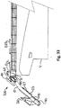
- a preferred embodiment of the chassis 10 can be used in any of the plow modes 100, 200 and 300 seen in Figures 13 , 26 and 37 , respectively.
- the skid and tool ends 13 and 15 of the elongated member 19 are substantially horizontal and joined by a midsection 27 which angles down from the skid end 13 to the tool end 15.
- a post receptacle 19 extends vertically through the skid end 13.
- Fork lift receptacles 21 extend widthwise across the top of the tool end 15 of the elongated member 11.
- One receptacle 21 is at the junction of the tool end 15 with the angled portion 17 of the elongated member 11.
- the other receptacle 21 is further to the rear of the elongated member 11 and immediately in front of a spaced pair of share connection plates 23 which extend above the elongated member 11.
- a transition member 25 extends above the tool end 15 of the elongated member 11 between the fork lift receptacles 21. As best seen in Figure 3 , the top surfaces of the receptacles 21, the share connection plates 23 and the transition member 25 form a substantially continuous transition surface 27 useful for launch and recovery purposes as hereinafter explained in relation to the second/trench cutting mode 200.
- a share connection slot 33 extends through the bottom of the tool end 15 of the elongated member 11 between the share connection plates 23.
- each of the plows 100, 200 and 300 has pulling points 65, as shown on tow bars 67 extending laterally from the skid end 13 of the elongated member 11, for connection of a pulling line L to the plow 100, 200 and 300.
- the pulling points 65 are symmetrically arranged in relation to the central longitudinal axes 101, 201 and 301 of the plows 100, 200 and 300 and are displaced from the points of contact of the plows 100, 200 and 300 with the deck D or roller R by a height less than a radius of the roller R to facilitate passage of the points of contact across the roller R.
- a transition attachment 70 is configured to extend between the skid and tool ends 13 and 15 on the bottom of the elongated member 11 of the chassis 10 when the chassis is used in either of its first/boulder clearing or third/trench cutting modes 100 or 300 as seen in Figures 13 , 26 and 37 .
- the transition attachment 70 extends in a generally horizontal wishbone shape with its tines 71 opening from its front to its rear ends 73 and 75.
- the top surface 77 of the transition attachment 70 is contoured to mate against the bottom surface 31 of the elongated member 11 of the chassis 10 against which the transition attachment 70 will be secured by pinning the transition member 25 of the chassis 10 between the transition clevis plates 83, as is best seen in Figures 16 and 39 .
- the bottom surface 79 of the transition attachment 70 is contoured to make contact with and pivot about fulcrum R on the stern of a plow transporting/towing vessel V, seen in Figures 21 and 22 and 44 and 45 , as the plow 100 or 300 crosses the fulcrum/roller R during its release from the vessel into the sea and during its retrieval from the sea onto the vessel.
- the shape of the attachment bottom surface 79 and the weight of the elongated member 11 and attachment 70 are coordinated so as to resist roll of the chassis 11 about the plow transition axis 103 or 303 as the plow 100 or 300 moves on the deck D toward or away from the fulcrum R.
- the fulcrum R is a roller and, as best seen in Figure 9 , the vertical longitudinal cross-sections of the attachment bottom surface 79 are concave.
- the radius of the concavity 79 is greater than the radius of the fulcrum R so as to facilitate passage of the transition attachment 70 across the fulcrum R during release and retrieval of the plows 100 and 300.
- the concavity 79 is symmetric about a longitudinal vertical plane centered on the attachment 70.
- the surface 79 can have any shape as long as it provides paths which facilitate the over-the-stern release and retrieval of the plow 100 or 300.
- the paths may be linear or planar and are preferably symmetrically defined by continuous opposite points of the attachment bottom surface 79.
- the front end 73 of the attachment 70 has a leading face 81 which is angled to smooth the transition to and from the skid end 13 of the elongated member 11 of the chassis 10.
- Back plates 85 are provided on the ends of the tines 71 for connection to the moldboards 90.
- the gap 87 between the tines 71 functions as a passageway for debris in the third/backfill mode 300, as is hereinafter explained.
- a preferred embodiment of the skid 40 is adaptable for use in any of the plow modes 100, 200 and 300 seen in Figures 13 , 26 and 37 , respectively.
- the skid 40 is shown configured for use in the first/boulder clearing and second/trench cutting modes 100 and 200, seen in Figures 13 and 26 , respectively.
- the parallel outer skis 41 of the skid 40 are in close proximity to each other, bolted on opposite sides of a center ski 43.
- a head 51 can be mounted on the front of the skis 41 and 43 in either the first/boulder clearing mode or for a first pass, the second/trench cutting mode 100 or 200.
- the outer skis 41 can be pivotally mounted on the center ski 43 using linkages 48 so that the outer skis 41 can be canted laterally upward from the center ski 43, provided the head 51 is not attached to the skis 41 and 43.
- the use of canted outer skis 41 is specially applicable to second and subsequent passes in this second/trench cutting mode 200, enabling the canted skis 41 to conform to the side walls of the trench T and facilitating the deepening of the trench T by a second and subsequent passes of the trench cutting plow 200.
- deeper trenches can be cut without need for a larger trenching plow.
- a post 45 which is pinned in a receptacle 47 in the center ski 43, extends upward to a top 49 which is convex from front to back.
- the outer skis 41 have receptacles 47 which are the same as the center ski receptacles 47.
- the boulder clearing head 5 1 is preferably added to the leading end of the skid 40 across the fronts of the skis 41 and 43.
- the leading faces 53 of the head 5 1 are angled rearward from a vertical, longitudinal center plane of the skid 40 and are tapered rearward from their top edges 55. The angled and tapered faces 53 will torque partially buried boulders out of the seabed and away from the skid 40 and, if necessary, allow the plow 200 to ride over a boulder B which strikes the head 51 below its top edges 55.
- either the bolted configuration of the skis 41 or the pivotal configuration of the skis 41 in an uncanted condition can be used, preferably with the head 51 in place for the first pass of the plow 200.
- the pivotal configuration of the skis 41 be used in the canted condition without the head 51.
- trenches up to 25 meters wide can be cut using multiple passes.
- a crossbeam 57 is shown for converting the outer skis 41 of the skid 40 shown in Figure 10 for use in the third/backfill mode 300.
- a crossbeam 57 spaces a pair of open ended receptacles 63 apart from a center post 59 extending upward from the midpoint of the crossbeam 57.
- two posts 45 are seated, one in each of the receptacles 47 of the two outer skis 41 as shown in Figure 10 .
- the posts 45 extend up from their respective outer skis 41, pass through their respective open ended receptacles 63 in the crossbeam 57 and are pinned with the skis 41 at the desired distance below the crossbeam 57.
- the crossbeam center post 59 is pinned in the chassis post receptacle 19 to set the desired height of the chassis 10 above the skis 41.
- the crossbeam 57 as shown has a front surface 61 configured to also serve as a spoil leveler in the backfill mode 300.
- the boulder clearing plow 100 includes the chassis 10, the skid 40, the transition attachment 70 and the moldboards 90.
- the skid 40 in the configuration shown in Figure 10 with the head 51 is mounted on and supports the skid end 13 of the chassis 10 above the seabed S.
- the moldboards 90 include primary, secondary and tertiary moldboards 91, 93 and 95 mounted on the tool end 15 of the chassis 10.
- the transition attachment 70 is mounted under the chassis 10 between the skid 40 and the primary moldboards 91.
- the chassis 10 is oriented upside down in comparison to its orientation as shown in Figures 1 and 2 . That is, in the boulder clearing plow 100, the skid end 13 is lower than the tool end 15 of the elongated member 11 and the skid post 45 extends upward through the receptacle 19 in the skid end 13 of the chassis 10.
- the primary moldboards 91 which may be permanently or detachably mounted on the tool end 15 of the chassis 10, are angled outward and rearward from the tool end 15 of the chassis 10 and the transition attachment 70.
- the secondary moldboards 93 are mounted below the primary moldboards 91 and the transition attachment 70 to increase the overall depth of the moldboards 91.
- the tertiary moldboards 95 are used when wider paths are to be cleared of boulders B. They are mounted at the free ends of the primary and secondary moldboards 91 and 93 and increase the length of the moldboards 90 for the full depth of the combined primary and secondary moldboards 91 and 93.
- a chassis extension 33 is connected by its front flange 35 to the back flange plate 3 1 of the chassis 10.
- a supporting structure 37 of beams and struts connects the chassis extension 33 to the tertiary moldboards 95.
- Recovery fins 97 are appended to the free ends of the moldboards 90. The fins 97 have divergingly arcute ends 99 for contact with the roller R during launch and recovery.
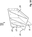
- the boulder clearing plow 100 may also include keel plates 110, shown in detail in Figure 18 .
- the keel plates 110 have a vertical center plate 111 and horizontal base plates 113 which extend laterally from the center plate 111.
- the base plates 113 and the center plates 111 support a vertical mounting plate 115 at an angle complementary to the angle of the moldboards 90.
- This structure is reinforced by small and large vertical support plates 117 and 119.
- At least one keel plate 110 mounted on the front of and extending under each set of moldboards 90.
- the keel plates 110 are mounted in parallel at the junctions of the secondary and tertiary moldboards 93 and 95.
- the primary function of the keel plates 110 is to steady the path of the boulder clearing plow 100 as the head 5 1 and moldboards 90 encounter boulders B, spoil M and/or other obstacles on the seabed S.
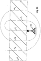
- FIGS 19-22 and 50 the over-the stern release ( Figures 19-22 ) and retrieval ( Figures 22-19 ) of the boulder clearing plow 100 from a vessel V to the seabed S or from the seabed S onto a vessel V, respectively, are illustrated.
- the plow 100 is preferably and as shown initially positioned on the deck D with its moldboards 90 aft and the longitudinal axis 101 of the plow 100 aligned on the transition axis 103 of the plow 100.
- the skid 40 and keel plates 110 provide the initial contact points or surfaces of the plow 100 with the deck D.
- Retrieval of the boulder clearing plow 100 at the end of the pulling line L from the seabed S is accomplished by reversal of the release method.
- the skid 40 will first contact the fulcrum/roller R.
- the pulling points 65 of the plow 100 are located so as to assure that the head 51 and skis 41 and 43 of the sled 40 will not hang-up on the fulcrum/roller R.
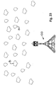
- FIG 23-25 the use of the boulder clearing plow 100 to clear boulders B from a path P on the seabed is illustrated.
- the plow 100 is positioned with the plow 100 bow-forward in the direction of an initial seabed path P 1 which will be at the center of the intended final path P.
- the pattern of the final path P spirals out from the initial path P 1 .
- the plow 100 is then propelled, perhaps at the end of the pulling line L, powered by a winch or by the travel of the vessel, along the initial path P 1 to clear boulders B from the initial path P 1 to the port and starboard sides of the plow 100.
- boulder clearing continues, if a wider path P is necessary, by repositioning the plow 100 bow-forward, for travel in a direction opposite the initial seabed path direction, on a second seabed path P 2 along, as shown, the starboard side of the initial path P 1 .
- the plow 100 is then propelled along the second path P 2 to clear boulders in the second path P 2 further away from the path P 1 .
- boulder clearing continues, if a wider path P is necessary, by repositioning the plow 100 bow-forward, for travel in the direction of the initial seabed path direction, on a third seabed path P 3 along the port side of the initial path P 1 .
- boulder clearing can further include repeating the widening along the path P resulting from the contiguity of the initial, second and third paths P 1 , P 2 and P 3 , as shown along paths P4 and P5.
- the boulder clearing process anticipates repetition of the widening steps to widen successively contiguous paths P n until a single path P of desired width has been cleared along the seabed.
- boulders B will be torqued out of the seabed and around the port or starboard side of the head 51, depending on which side of the head 51 strikes the boulders B.
- the trailing moldboards 90 will torque and push the boulders B further to port or starboard away from the plow 100.
- P 2-n On ensuing paths P 2-n , only the outside of the head 51 and the outside moldboards 90 are on a path to strike the boulders B, pushing them further away from the initial path P 1 .
- boulders B which have been pushed aside will be deposited in a small spoil heap H created aft of the plow 100 by the partial penetration of the seabed by the moldboards 90.
- the trench cutting plow 200 includes the chassis 10, the skid 40, the moldboards 90 and the share 210.
- the skid 40 in the configuration shown in Figure 10 , is mounted on and supports the skid end 13 of the chassis 10 above the seabed.
- the moldboards 90 initially include only the primary moldboards 91 mounted on the tool end 15 of the chassis 10. If more than one pass of a trench cutting plow 200 is to be performed, the secondary and tertiary moldboards 93 and 95 can be added.
- Wedges (not shown) can be positioned between the chassis 10 and the moldboards 90 to angle the moldboards at a desired angle upward and rearward from the chassis 10 for second and subsequent passes of the plow.
- the transition attachment 70 is not used.
- the head 51 may optionally be attached to the skid 40 in the first pass of the second/trench cutting mode 200.
- the chassis 10 is oriented right-side up as shown in Figures 1 and 2 . That is, in the trench cutting plow 200, the skid end 13 is higher than the tool end 15 of the elongated member 11 and the skid post 45 extends upward through the receptacle 19 in the skid end 13 of the chassis 10.
- the plow share 210 may be permanently or detachably mounted on the chassis 10.
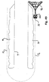
- a preferred embodiment of the share 210 shown in Figures 26-32 includes a shoe box 211 joining the bottoms of center ribs 213 and side plates 215 which support the parting plates 217 of the share 210.
- a vertical plate 219 aligned with the shoe box 211 extends upwardly above the parting plates 217 and is inserted between the share connection plates 23 on the chassis 10.
- a pin 221 inserted through a boss 223 on the vertical plate 219 and the connection plates 23 secures the share 210 to the chassis 10.
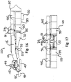
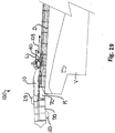
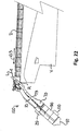
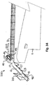
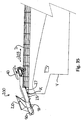
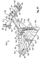
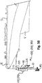
- FIGS 33-36 the over-the stern release ( Figures 36-33 ) and retrieval ( Figures 33-36 ) of the trench cutting plow 200 from the vessel V to the seabed S and from the seabed S onto the vessel V, respectively, are illustrated.
- the plow 200 herein described is initially positioned upside down on the deck D with moldboards 90 aft and the longitudinal axis 201 of the plow 200 aligned on the plow's transition axis 203.
- the arcuate top 49 of the skid post 45 and the free ends of the moldboards 90 provide the initial contact points or surfaces with the deck D.
- the cantilevered weight of the plow 200 causes the plow 200 to pivot on the transition surface 27 of the transition member 25, allowing the moldboards 90 to drop toward the seabed S and the skid post 45 to rise from the deck D.
- all contact between the plow 200 and the vessel V transfers to the angled portion 17 of the chassis elongated member 11 and the fulcrum/roller R of the vessel V.
- Retrieval of the trench cutting plow 200 at the end of the pulling line L from the seabed S is accomplished by reversal of the release method.
- the arcuate top 49 of the skid post 45 will first contact the fulcrum/roller R.
- the pulling points 65 of the plow 110 are located so as to assure that the post 45 will not hang up on the fulcrum/roller R.
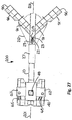
- the backfill plow 300 for backfilling spoil into a seabed trench, includes the chassis 10, the skid 40 configured to straddle the trench being backfilled, the moldboards 90 mounted on the chassis 10 forward of the skid 40 and the blade 310 mounted on and spanning the bottom edges of the moldboards 90.
- the chassis 10 is oriented upside down in comparison to its orientation as shown in Figures 1 and 2 . That is, in the backfill plow 300, the skid end 13 is lower than the tool end 15 of the elongated member 11, as in the first/boulder clearing mode 100 shown in Figure 13 , and the crossbeam center post 59 extends upward through the receptacle 19 in the skid end 13 of the chassis 10, similar to the post 45 in the first/boulder clearing mode 100 shown in Figure 13 . However, the chassis 10 is oriented in reverse in comparison to the first/boulder clearing mode 100 shown in Figure 13 , so that the skid 40 is at the trailing end of the backfill plow 300. In comparison to the first/boulder clearing mode 100, the skis 41 are also reversed in the third/boulder clearing mode 300 for forward travel in a trailing position.
- the moldboards 90 including the primary moldboards 91, the secondary moldboards 93 and the tertiary moldboards 95, are mounted on the chassis 10 in the same way as described in relation to the first/boulder clearing mode 100 of Figures 13-17 by use of the chassis extension 33 and supporting structure 37.
- the transition attachment 70 is also mounted to the chassis 10 in the same manner as described in relation to the first/boulder clearing mode 100 of Figures 13-17 .
- the recovery fins 97 are appended to the free ends of the tertiary moldboards 95 as described in relation to the first/boulder clearing mode 100 of Figures 13-17 .
- the blade 310 has a passage 311 at its rear apex 313.
- the passage 311 is configured to dispense the spoil collected by the blade 310 and funneled by the moldboards 90 onto the top of a pipe or cable C disposed in the trench T below the passage 311.
- the side edges of the blade 310 are secured to the lower portions of their respective moldboards 90 by use of side plates 315 and to the chassis extension 33 by use of an upright mounting structure 317.
- the mounting structure 3 1 7 is centered on the leading edge 319 of the blade 310 and, as shown, extends from the blade edge 319 to the passage 311.
- the blade 310 may be stiffened by ribs 321. As shown, the passage 311 is slightly greater than semicircular with a diameter 323 parallel to the blade leading edge 319. The stiffening ribs 321 fan out from points along the passage circumference 325 to respective points along the blade leading edge 319.
- the backfill plow 300 preferably further includes a flapper board 340 aft of the passage 311.
- the flapper board 340 includes a plate 341 fixed to and swinging below a horizontal shaft 343.
- the shaft 343 is journalled to reciprocate on an axis parallel to the passage diameter 323.
- a weight 345 biases the plate 341 toward a vertical orientation.
- the slapping action of the flapper board 340 fragments spoil discharged through the blade passage 311.
- Large and small stiffeners 347 and 349 reinforce the plate 341.
- the reciprocating swing of the plate 341 on its shaft 343 is caused as water and spoil discharging through the passage 311 swings the plate 341 toward the rear and the weight 345 causes the plate 341 to swing back toward vertical.
- the backfill plow 300 may also include keel plates 370, at least one keel plate 370 extending on opposite sides of the spoil passage 311.
- the keel plates 110 shown in Figure 18 for use in the first/boulder clearing mode 100, can be used in the third/backfill mode 300 except that, in the backfill mode 300, they are mounted on the front of the moldboards 90 and extend under the blade 310.
- the keel plates 370 are mounted in parallel at the junctions of the secondary and tertiary moldboards 93 and 95.
- the primary function of the keel plates 370 is to steady the path of the backfill plow 300 as the blade 3 10 and moldboards 90 encounter and collect spoil M on the seabed S.
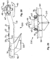
- FIGS 43-46 the over-the stern release ( Figures 46-43 ) and retrieval ( Figures 43-46 ) of the backfill plow 300 from a vessel V to the seabed S or from the seabed S onto a vessel V, respectively, are illustrated.
- the plow 300 described herein is initially positioned on the deck D with moldboards 90 aft and the longitudinal axis 301 of the plow 300 aligned on the transition axis 303 of the plow 300.
- the skid 40 and bottoms of the keel plates 370 provide the initial contact points with the deck D.
- Retrieval of the backfill plow 300 at the end of the pulling line L from the seabed S is accomplished by reversal of the release method.
- the skid 40 will first contact the fulcrum/roller R.
- the pulling points 65 of the plow 300 are located so as to assure that the head 51 and skis 41 and 43 of the sled 40 will not hang up on the fulcrum/roller R.
- the discharged spoil M is fragmented, as shown by the flapper board 340, before the discharged spoil M reaches the pipe P and the spoil M discharged onto the pipe P and into the trench T is leveled by the front surface 61 of the skid crossbar 57.
- the use of the passage 311 to discharge the spoil M directly onto, rather than to the sides of, the pipe P reduces the likelihood that the more dense spoil M will lift the pipe P in the trench T during backfilling.
- the boulder clearing plow 100 seen in Figure 13 can be used to narrow the width of the trench T. This is accomplished by aligning the longitudinal axis 101 of the plow 100 outside of the spoil M one side of the trench T, as shown with only the starboard moldboards 90 pushing the spoil M. On the first pass P a the spoil M in the path of the starboard moldboards will be pushed toward or into the trench T. When the first pass P a is completed, the plow 100 is aligned on the other side of the trench T, as shown again with only the starboard moldboards 90 pushing the spoil M.
- the spoil M in the path of the starboard moldboards will be pushed toward or into the trench T.
- the process can be repeated for passes P n until the trench T is filled or until the trench T is sufficiently filled to complete backfilling using the backfill plow 300.
- the plows 100, 200 or 300 can be retrieved by use of the tow line L connected to the retrieval fins 97.
- the orientation of the plow 100; 200 or 300 can be rotated 180° about the axis of the tow line L to a suitable retrieval position. In either 180° orientation, the arcuate ends 99 of the fins 97 will enable the plow 100, 200 or 300 to pass over the fulcrum/roller R.
- the plows 100, 200 and 300 are made using steel plates which are welded, bolted or pinned, depending on the intended permanency or detachability of the components being connected.
- the same chassis 10, skids 40, transition attachment 70, moldboards 90, and keel plates 110 can be configured into three different modes of operation and the share 210 and blade 310 added as needed for their respective modes.
- the need for a large vessel, cranes and supporting equipment is eliminated since the plow modes 100, 200 and 300 are all capable of over-the-stern launch and recovery.
- ROV remotely operated vehicle
Landscapes
- Engineering & Computer Science (AREA)
- Mining & Mineral Resources (AREA)
- Mechanical Engineering (AREA)
- Civil Engineering (AREA)
- General Engineering & Computer Science (AREA)
- Structural Engineering (AREA)
- Soil Working Implements (AREA)
- Earth Drilling (AREA)
- Underground Or Underwater Handling Of Building Materials (AREA)
- Excavating Of Shafts Or Tunnels (AREA)
Priority Applications (1)
| Application Number | Priority Date | Filing Date | Title |
|---|---|---|---|
| HRP20182036TT HRP20182036T1 (hr) | 2012-11-30 | 2018-12-04 | Plug za zatrpavanje |
Applications Claiming Priority (3)
| Application Number | Priority Date | Filing Date | Title |
|---|---|---|---|
| US13/691,076 US10323383B2 (en) | 2012-11-30 | 2012-11-30 | Seabed plow capable of over-the-stern release and retrieval in any of boulder clearing, trenching and backfill configurations |
| PCT/IB2013/000697 WO2014083391A1 (fr) | 2012-11-30 | 2013-04-16 | Charrue pour fond marin apte à être mise à l'eau et récupérée par-dessus la poupe pour des opérations d'évacuation d'éboulis, de creusement de tranchées et de remblayage |
| EP13728243.0A EP2929096B1 (fr) | 2012-11-30 | 2013-04-16 | Charrue pour fond marin apte à être mise à l'eau et récupérée par-dessus la poupe pour des opérations d'évacuation d'éboulis |
Related Parent Applications (2)
| Application Number | Title | Priority Date | Filing Date |
|---|---|---|---|
| EP13728243.0A Division-Into EP2929096B1 (fr) | 2012-11-30 | 2013-04-16 | Charrue pour fond marin apte à être mise à l'eau et récupérée par-dessus la poupe pour des opérations d'évacuation d'éboulis |
| EP13728243.0A Division EP2929096B1 (fr) | 2012-11-30 | 2013-04-16 | Charrue pour fond marin apte à être mise à l'eau et récupérée par-dessus la poupe pour des opérations d'évacuation d'éboulis |
Publications (2)
| Publication Number | Publication Date |
|---|---|
| EP3249108A1 true EP3249108A1 (fr) | 2017-11-29 |
| EP3249108B1 EP3249108B1 (fr) | 2018-09-05 |
Family
ID=48607322
Family Applications (3)
| Application Number | Title | Priority Date | Filing Date |
|---|---|---|---|
| EP13728243.0A Active EP2929096B1 (fr) | 2012-11-30 | 2013-04-16 | Charrue pour fond marin apte à être mise à l'eau et récupérée par-dessus la poupe pour des opérations d'évacuation d'éboulis |
| EP17181225.8A Active EP3249109B1 (fr) | 2012-11-30 | 2013-04-16 | Procédé de remblayage pour déblais dans le fond marin |
| EP17180897.5A Not-in-force EP3249108B1 (fr) | 2012-11-30 | 2013-04-16 | Charrue de remblayage |
Family Applications Before (2)
| Application Number | Title | Priority Date | Filing Date |
|---|---|---|---|
| EP13728243.0A Active EP2929096B1 (fr) | 2012-11-30 | 2013-04-16 | Charrue pour fond marin apte à être mise à l'eau et récupérée par-dessus la poupe pour des opérations d'évacuation d'éboulis |
| EP17181225.8A Active EP3249109B1 (fr) | 2012-11-30 | 2013-04-16 | Procédé de remblayage pour déblais dans le fond marin |
Country Status (11)
| Country | Link |
|---|---|
| US (1) | US10323383B2 (fr) |
| EP (3) | EP2929096B1 (fr) |
| JP (1) | JP2016503846A (fr) |
| AU (2) | AU2013350868B2 (fr) |
| BR (1) | BR112015012511A2 (fr) |
| CA (3) | CA3043417A1 (fr) |
| DK (3) | DK2929096T3 (fr) |
| ES (3) | ES2762276T3 (fr) |
| HR (3) | HRP20192206T1 (fr) |
| PT (3) | PT3249108T (fr) |
| WO (1) | WO2014083391A1 (fr) |
Families Citing this family (14)
| Publication number | Priority date | Publication date | Assignee | Title |
|---|---|---|---|---|
| US9562343B2 (en) * | 2013-10-16 | 2017-02-07 | Philip Paull | Cable-laying plow attachment for a backhoe and method for using the same |
| US9657455B2 (en) | 2015-06-24 | 2017-05-23 | Michael W. N. Wilson | Over-the-stern deep digging trenching plow with instrumentation for assessing the protective capabilities of a seabed trench |
| EP3216925A1 (fr) * | 2016-03-08 | 2017-09-13 | Soil Machine Dynamics Limited | Procédé et appareil de formation d'une tranchée dans un fond marin |
| US20190345688A1 (en) * | 2018-05-08 | 2019-11-14 | Atlantic Marine And Aviation Llp | Subsea clearing apparatus |
| GB2573530A (en) * | 2018-05-08 | 2019-11-13 | Atlantic Marine & Aviation Llp | Subsea clearing apparatus |
| GB2580612B (en) | 2019-01-16 | 2021-07-07 | Osbit Ltd | Subsea plough |
| EP3800297B1 (fr) | 2019-10-02 | 2026-04-08 | Soil Machine Dynamics Limited | Procédé et appareil pour l'insertion d'un objet allongé dans une tranchée dans un fond marin |
| EP3832026B1 (fr) | 2019-12-05 | 2023-07-26 | Soil Machine Dynamics Limited | Appareil de localisation d'objet allongé dans une tranchée dans un plancher d'un corps d'eau |
| EP3882401B1 (fr) | 2020-03-20 | 2023-09-06 | Soil Machine Dynamics Limited | Appareil et procédé d'insertion d'un objet allongé dans une tranchée |
| WO2021221606A1 (fr) * | 2020-04-28 | 2021-11-04 | Yilit Michael S | Dispositif de pose de tuyau |
| EP4047141A1 (fr) * | 2021-02-22 | 2022-08-24 | Nexans | Soc pour l'enfouissement de câbles à chargement par le haut |
| US12043979B2 (en) * | 2021-06-28 | 2024-07-23 | Soil Machine Dynamics Limited | Apparatus for inserting an elongate object into a trench |
| CN115614545B (zh) * | 2022-10-28 | 2025-08-12 | 江苏国行重工科技有限公司 | 水下回填犁 |
| CN117552493B (zh) * | 2024-01-10 | 2024-03-12 | 山西省水利建筑工程局集团有限公司 | 一种渠道清淤疏浚设备及其疏浚方法 |
Citations (2)
| Publication number | Priority date | Publication date | Assignee | Title |
|---|---|---|---|---|
| FR2284715A1 (fr) * | 1974-09-11 | 1976-04-09 | Kompeer Antoine | Dispositif pour creuser une tranchee |
| EP0116410A1 (fr) * | 1983-01-20 | 1984-08-22 | The British Petroleum Company p.l.c. | Dispositif de remblayage de tranchées |
Family Cites Families (48)
| Publication number | Priority date | Publication date | Assignee | Title |
|---|---|---|---|---|
| US416999A (en) * | 1889-12-10 | Dredging-scraper | ||
| US3757A (en) * | 1844-09-24 | Improvement in ditching-machines | ||
| US2194947A (en) | 1937-07-23 | 1940-03-26 | Western Union Telegraph Co | Method and apparatus for determining topography of ocean bed |
| FR1156475A (fr) | 1956-07-20 | 1958-05-16 | Machine à poser des tuyaux ou câbles souples en tranchée | |
| DE1105355B (de) | 1957-01-30 | 1961-04-20 | Kaessbohrer Fahrzeug Karl | Fahrbares Geraet fuer in das Erdreich laufend zu verlegende Gegenstaende |
| US3540226A (en) | 1966-04-15 | 1970-11-17 | Buddy L Sherrod | Method of towing a vessel on a body of water |
| US3347054A (en) | 1966-04-15 | 1967-10-17 | Buddy L Sherrod | Underwater pipe trenching device |
| US3732701A (en) | 1971-08-19 | 1973-05-15 | R Lynch | Underwater pipeline trenching apparatus |
| FR2278854A1 (fr) | 1974-07-19 | 1976-02-13 | Comex | Engin automoteur pour travailler au fond de l'eau |
| GB1498242A (en) | 1974-07-26 | 1978-01-18 | Sumitomo Electric Industries | Movable cable plow for burying underwater cable |
| US4147390A (en) * | 1975-08-06 | 1979-04-03 | Union Miniere S.A. | Nodule dredging apparatus and process |
| SE401141B (sv) | 1976-05-03 | 1978-04-24 | Ericsson Telefon Ab L M | Forleggningsverktyg for forleggning av sjokabel i sjobotten |
| USD248302S (en) * | 1976-11-04 | 1978-06-27 | Zoller Richard D | Ground scraper for closing ditches and the like |
| JPS5952258B2 (ja) | 1977-01-25 | 1984-12-19 | 株式会社小松製作所 | 地下埋設物埋設装置 |
| US4245927A (en) * | 1978-11-07 | 1981-01-20 | Wharton Engineers (Elstree) Limited | Laying of pipes or cables in a bed of material |
| US4329793A (en) | 1979-11-01 | 1982-05-18 | The British Petroleum Company Limited | Soil moving device |
| US4538937A (en) | 1981-01-19 | 1985-09-03 | Lyntech Corporation | Marine continuous pipe laying system |
| IT1138764B (it) | 1981-05-04 | 1986-09-17 | Snam Progetti | Dispositivo per interramento o dissotterramento di condotte subacquee |
| US4428132A (en) | 1981-09-11 | 1984-01-31 | The British Petroleum Company P.L.C. | Trenching plow with plow carriage on curved supporting track |
| AU557934B2 (en) | 1981-12-19 | 1987-01-15 | British Petroleum Company Limited, The | Underwater plough and conduit layer |
| GB8331892D0 (en) | 1983-11-30 | 1984-01-04 | Soil Machine Dynamics Ltd | Ploughs |
| JPS60131016A (ja) | 1983-12-19 | 1985-07-12 | 住友電気工業株式会社 | 海底調査兼埋設装置 |
| GB8524410D0 (en) | 1985-10-03 | 1985-11-06 | Soil Machine Dynamics Ltd | Pipeline/cable plough |
| GB8714515D0 (en) | 1987-06-20 | 1987-07-22 | Land & Marine Eng Ltd | Seabed trenching apparatus |
| DE8709260U1 (de) | 1987-07-04 | 1987-12-17 | Peter Lancier Maschinenbau-Hafenhütte GmbH & Co KG, 48167 Münster | Kabelpflug |
| JPH01148012A (ja) | 1987-12-01 | 1989-06-09 | Nec Corp | ケーブル埋設機 |
| US4992000A (en) | 1989-06-19 | 1991-02-12 | Central States Underwater Contracting, Inc. | Underwater trenching system |
| US5288172A (en) | 1991-05-28 | 1994-02-22 | Cal Dive International | Water jet system for trenching of pipelines |
| US5462389A (en) * | 1993-01-04 | 1995-10-31 | At&T Ipm Corp. | Undersea cable burial plowshare and sled apparatus |
| GB9401351D0 (en) | 1994-01-25 | 1994-03-23 | Soil Machine Dynamics Ltd | Trenching plough |
| NZ313134A (en) * | 1995-07-20 | 1998-11-25 | Geoteknisk Inst | Method and device or plough for burying a conduit under water |
| EP0816574A1 (fr) | 1996-07-03 | 1998-01-07 | Jan De Nul N.V. | Appareil pour enterrer des conduites ou câbles au fond de la mer |
| JPH1037237A (ja) | 1996-07-25 | 1998-02-10 | Sekisui Plant Syst Kk | 溝の埋め戻し装置ならびに溝の埋め戻し方法および溝掘り装置付き溝の埋め戻し装置 |
| US5855181A (en) | 1997-02-14 | 1999-01-05 | Oxford; Sefton M.D. | Fixed shank plow anchor |
| WO1999013171A1 (fr) | 1997-09-05 | 1999-03-18 | Soil Machine Dynamics Limited | Charrue sous-marine |
| US6050009A (en) | 1997-11-04 | 2000-04-18 | Coflexip, S.A. | Steerable underwater plow |
| US6061932A (en) | 1998-04-29 | 2000-05-16 | Coflexip Stena Offshore | Steerable underwater plow with movable body member |
| GB9922247D0 (en) | 1999-09-21 | 1999-11-17 | Engineering Business Ltd | Improvements to submarine ploughs |
| JP2001259562A (ja) | 2000-03-14 | 2001-09-25 | Ge Systems Kk | 腐敗性廃棄物の処理システム |
| GB2368560A (en) | 2000-11-02 | 2002-05-08 | Lawborough Consultants Ltd | Vessel and apparatus for clearing seabed mines |
| GB0123658D0 (en) * | 2001-10-02 | 2001-11-21 | Global Marine Systems Ltd | Cable or pipe retrieval and burial apparatus and methods |
| US6821054B2 (en) | 2002-08-19 | 2004-11-23 | Horizon Vessels, Inc. | Method and system for laying pipe through the use of a plow |
| US7475649B2 (en) | 2006-07-18 | 2009-01-13 | Shepherd John D | Davit system for small boats |
| GB0623450D0 (en) * | 2006-11-24 | 2007-01-03 | Drabble Ray | Faunal friendly dredging system |
| GB2448909B (en) | 2007-05-02 | 2010-12-15 | Ecosse Subsea Systems Ltd | A plough for excavating a subsea channel and sea-going vessel comprising a plough |
| CN101187211B (zh) | 2007-06-25 | 2010-09-22 | 中国海洋石油总公司 | 一种具有双重功能的海底挖掘机 |
| GB201018670D0 (en) | 2010-11-05 | 2010-12-22 | Brupat Ltd | Anchor data communicaiton system |
| EP2638608B1 (fr) | 2010-11-10 | 2024-05-15 | Husqvarna AB | Machine pour découper des tranchées et placer des conduits/câbles |
-
2012
- 2012-11-30 US US13/691,076 patent/US10323383B2/en not_active Expired - Fee Related
-
2013
- 2013-04-16 ES ES13728243T patent/ES2762276T3/es active Active
- 2013-04-16 WO PCT/IB2013/000697 patent/WO2014083391A1/fr not_active Ceased
- 2013-04-16 CA CA3043417A patent/CA3043417A1/fr not_active Abandoned
- 2013-04-16 PT PT17180897T patent/PT3249108T/pt unknown
- 2013-04-16 DK DK13728243.0T patent/DK2929096T3/da active
- 2013-04-16 EP EP13728243.0A patent/EP2929096B1/fr active Active
- 2013-04-16 CA CA3043420A patent/CA3043420A1/fr not_active Abandoned
- 2013-04-16 CA CA2892034A patent/CA2892034C/fr not_active Expired - Fee Related
- 2013-04-16 ES ES17181225T patent/ES2751936T3/es active Active
- 2013-04-16 PT PT137282430T patent/PT2929096T/pt unknown
- 2013-04-16 PT PT171812258T patent/PT3249109T/pt unknown
- 2013-04-16 ES ES17180897T patent/ES2701008T3/es active Active
- 2013-04-16 DK DK17180897.5T patent/DK3249108T3/da active
- 2013-04-16 AU AU2013350868A patent/AU2013350868B2/en not_active Ceased
- 2013-04-16 DK DK17181225.8T patent/DK3249109T3/da active
- 2013-04-16 HR HRP20192206TT patent/HRP20192206T1/hr unknown
- 2013-04-16 BR BR112015012511A patent/BR112015012511A2/pt not_active IP Right Cessation
- 2013-04-16 JP JP2015544549A patent/JP2016503846A/ja active Pending
- 2013-04-16 EP EP17181225.8A patent/EP3249109B1/fr active Active
- 2013-04-16 EP EP17180897.5A patent/EP3249108B1/fr not_active Not-in-force
-
2018
- 2018-05-15 AU AU2018203403A patent/AU2018203403B2/en not_active Ceased
- 2018-12-04 HR HRP20182036TT patent/HRP20182036T1/hr unknown
-
2019
- 2019-10-15 HR HRP20191850TT patent/HRP20191850T1/hr unknown
Patent Citations (2)
| Publication number | Priority date | Publication date | Assignee | Title |
|---|---|---|---|---|
| FR2284715A1 (fr) * | 1974-09-11 | 1976-04-09 | Kompeer Antoine | Dispositif pour creuser une tranchee |
| EP0116410A1 (fr) * | 1983-01-20 | 1984-08-22 | The British Petroleum Company p.l.c. | Dispositif de remblayage de tranchées |
Also Published As
| Publication number | Publication date |
|---|---|
| AU2013350868A1 (en) | 2015-06-11 |
| CA2892034C (fr) | 2020-05-05 |
| AU2013350868B2 (en) | 2018-03-01 |
| AU2018203403B2 (en) | 2019-09-26 |
| CA3043420A1 (fr) | 2014-06-05 |
| EP3249109B1 (fr) | 2019-07-24 |
| EP2929096A1 (fr) | 2015-10-14 |
| ES2701008T3 (es) | 2019-02-20 |
| BR112015012511A2 (pt) | 2017-07-11 |
| ES2751936T3 (es) | 2020-04-02 |
| JP2016503846A (ja) | 2016-02-08 |
| WO2014083391A1 (fr) | 2014-06-05 |
| PT3249108T (pt) | 2018-12-12 |
| EP2929096B1 (fr) | 2019-09-18 |
| HRP20191850T1 (hr) | 2020-02-07 |
| US20140150303A1 (en) | 2014-06-05 |
| CA3043417A1 (fr) | 2014-06-05 |
| EP3249109A1 (fr) | 2017-11-29 |
| AU2018203403A1 (en) | 2018-06-07 |
| DK3249109T3 (da) | 2019-10-14 |
| DK2929096T3 (da) | 2019-12-16 |
| CA2892034A1 (fr) | 2014-06-05 |
| US10323383B2 (en) | 2019-06-18 |
| EP3249108B1 (fr) | 2018-09-05 |
| HRP20182036T1 (hr) | 2019-03-22 |
| PT2929096T (pt) | 2019-12-24 |
| DK3249108T3 (da) | 2019-01-02 |
| ES2762276T3 (es) | 2020-05-22 |
| HRP20192206T1 (hr) | 2020-03-06 |
| PT3249109T (pt) | 2019-10-28 |
Similar Documents
| Publication | Publication Date | Title |
|---|---|---|
| EP3249108B1 (fr) | Charrue de remblayage | |
| US9422690B2 (en) | Method and apparatus for performing burial assessment surveys | |
| US4091629A (en) | Marine pipeline installation system | |
| NL2009108C2 (en) | Vessel for forming a trench in a water bottom. | |
| JP2019214934A (ja) | 埋設アセスメント調査を実行するための方法および装置 | |
| JP4700761B1 (ja) | 水底均し装置 | |
| US20160237643A1 (en) | Dredger actuated from land | |
| JP2005504202A (ja) | ケーブル又はパイプの回収及び埋設装置及び方法 | |
| KR101140789B1 (ko) | 해저케이블 매설장치 | |
| US4844658A (en) | Apparatus for burying pipe under water | |
| NL2009062C2 (en) | Vessel for forming a trench in a water bottom. |
Legal Events
| Date | Code | Title | Description |
|---|---|---|---|
| PUAI | Public reference made under article 153(3) epc to a published international application that has entered the european phase |
Free format text: ORIGINAL CODE: 0009012 |
|
| STAA | Information on the status of an ep patent application or granted ep patent |
Free format text: STATUS: REQUEST FOR EXAMINATION WAS MADE |
|
| 17P | Request for examination filed |
Effective date: 20170712 |
|
| AC | Divisional application: reference to earlier application |
Ref document number: 2929096 Country of ref document: EP Kind code of ref document: P |
|
| AK | Designated contracting states |
Kind code of ref document: A1 Designated state(s): AL AT BE BG CH CY CZ DE DK EE ES FI FR GB GR HR HU IE IS IT LI LT LU LV MC MK MT NL NO PL PT RO RS SE SI SK SM TR |
|
| RAP1 | Party data changed (applicant data changed or rights of an application transferred) |
Owner name: ECOSSE SUBSEA SYSTEMS LIMITED |
|
| RIN1 | Information on inventor provided before grant (corrected) |
Inventor name: WILSON, MICHAEL W. N. |
|
| RAP1 | Party data changed (applicant data changed or rights of an application transferred) |
Owner name: WILSON, MICHAEL W. N. |
|
| GRAP | Despatch of communication of intention to grant a patent |
Free format text: ORIGINAL CODE: EPIDOSNIGR1 |
|
| STAA | Information on the status of an ep patent application or granted ep patent |
Free format text: STATUS: GRANT OF PATENT IS INTENDED |
|
| 111L | Licence recorded |
Designated state(s): GB Free format text: EXCLUSIVE LICENSE Name of requester: MASFAB LIMITED, GB Effective date: 20171019 |
|
| RAP1 | Party data changed (applicant data changed or rights of an application transferred) |
Owner name: ECOSSE SUBSEA SYSTEMS LIMITED |
|
| RIC1 | Information provided on ipc code assigned before grant |
Ipc: H02G 1/10 20060101ALI20180222BHEP Ipc: B63B 27/16 20060101ALI20180222BHEP Ipc: E02F 5/10 20060101AFI20180222BHEP Ipc: E02F 5/12 20060101ALI20180222BHEP Ipc: E02F 5/14 20060101ALI20180222BHEP Ipc: E02F 5/02 20060101ALI20180222BHEP |
|
| INTG | Intention to grant announced |
Effective date: 20180314 |
|
| GRAS | Grant fee paid |
Free format text: ORIGINAL CODE: EPIDOSNIGR3 |
|
| GRAA | (expected) grant |
Free format text: ORIGINAL CODE: 0009210 |
|
| STAA | Information on the status of an ep patent application or granted ep patent |
Free format text: STATUS: THE PATENT HAS BEEN GRANTED |
|
| 111L | Licence recorded |
Designated state(s): GB Free format text: EXCLUSIVE LICENSE Name of requester: MASFAB LIMITED, GB Effective date: 20171019 |
|
| AC | Divisional application: reference to earlier application |
Ref document number: 2929096 Country of ref document: EP Kind code of ref document: P |
|
| AK | Designated contracting states |
Kind code of ref document: B1 Designated state(s): AL AT BE BG CH CY CZ DE DK EE ES FI FR GB GR HR HU IE IS IT LI LT LU LV MC MK MT NL NO PL PT RO RS SE SI SK SM TR |
|
| REG | Reference to a national code |
Ref country code: GB Ref legal event code: FG4D |
|
| REG | Reference to a national code |
Ref country code: CH Ref legal event code: EP |
|
| REG | Reference to a national code |
Ref country code: AT Ref legal event code: REF Ref document number: 1037958 Country of ref document: AT Kind code of ref document: T Effective date: 20180915 |
|
| REG | Reference to a national code |
Ref country code: IE Ref legal event code: FG4D |
|
| REG | Reference to a national code |
Ref country code: DE Ref legal event code: R096 Ref document number: 602013043422 Country of ref document: DE |
|
| REG | Reference to a national code |
Ref country code: HR Ref legal event code: TUEP Ref document number: P20182036 Country of ref document: HR |
|
| REG | Reference to a national code |
Ref country code: PT Ref legal event code: SC4A Ref document number: 3249108 Country of ref document: PT Date of ref document: 20181212 Kind code of ref document: T Free format text: AVAILABILITY OF NATIONAL TRANSLATION Effective date: 20181204 |
|
| REG | Reference to a national code |
Ref country code: NL Ref legal event code: FP |
|
| REG | Reference to a national code |
Ref country code: DK Ref legal event code: T3 Effective date: 20181217 |
|
| REG | Reference to a national code |
Ref country code: LT Ref legal event code: MG4D |
|
| REG | Reference to a national code |
Ref country code: SE Ref legal event code: TRGR |
|
| PG25 | Lapsed in a contracting state [announced via postgrant information from national office to epo] |
Ref country code: LT Free format text: LAPSE BECAUSE OF FAILURE TO SUBMIT A TRANSLATION OF THE DESCRIPTION OR TO PAY THE FEE WITHIN THE PRESCRIBED TIME-LIMIT Effective date: 20180905 Ref country code: RS Free format text: LAPSE BECAUSE OF FAILURE TO SUBMIT A TRANSLATION OF THE DESCRIPTION OR TO PAY THE FEE WITHIN THE PRESCRIBED TIME-LIMIT Effective date: 20180905 Ref country code: BG Free format text: LAPSE BECAUSE OF FAILURE TO SUBMIT A TRANSLATION OF THE DESCRIPTION OR TO PAY THE FEE WITHIN THE PRESCRIBED TIME-LIMIT Effective date: 20181205 |
|
| REG | Reference to a national code |
Ref country code: NO Ref legal event code: T2 Effective date: 20180905 |
|
| REG | Reference to a national code |
Ref country code: AT Ref legal event code: MK05 Ref document number: 1037958 Country of ref document: AT Kind code of ref document: T Effective date: 20180905 |
|
| REG | Reference to a national code |
Ref country code: ES Ref legal event code: FG2A Ref document number: 2701008 Country of ref document: ES Kind code of ref document: T3 Effective date: 20190220 |
|
| PG25 | Lapsed in a contracting state [announced via postgrant information from national office to epo] |
Ref country code: AL Free format text: LAPSE BECAUSE OF FAILURE TO SUBMIT A TRANSLATION OF THE DESCRIPTION OR TO PAY THE FEE WITHIN THE PRESCRIBED TIME-LIMIT Effective date: 20180905 Ref country code: LV Free format text: LAPSE BECAUSE OF FAILURE TO SUBMIT A TRANSLATION OF THE DESCRIPTION OR TO PAY THE FEE WITHIN THE PRESCRIBED TIME-LIMIT Effective date: 20180905 |
|
| REG | Reference to a national code |
Ref country code: HR Ref legal event code: T1PR Ref document number: P20182036 Country of ref document: HR |
|
| REG | Reference to a national code |
Ref country code: GR Ref legal event code: EP Ref document number: 20180403652 Country of ref document: GR Effective date: 20190404 |
|
| PG25 | Lapsed in a contracting state [announced via postgrant information from national office to epo] |
Ref country code: RO Free format text: LAPSE BECAUSE OF FAILURE TO SUBMIT A TRANSLATION OF THE DESCRIPTION OR TO PAY THE FEE WITHIN THE PRESCRIBED TIME-LIMIT Effective date: 20180905 Ref country code: CZ Free format text: LAPSE BECAUSE OF FAILURE TO SUBMIT A TRANSLATION OF THE DESCRIPTION OR TO PAY THE FEE WITHIN THE PRESCRIBED TIME-LIMIT Effective date: 20180905 Ref country code: AT Free format text: LAPSE BECAUSE OF FAILURE TO SUBMIT A TRANSLATION OF THE DESCRIPTION OR TO PAY THE FEE WITHIN THE PRESCRIBED TIME-LIMIT Effective date: 20180905 Ref country code: EE Free format text: LAPSE BECAUSE OF FAILURE TO SUBMIT A TRANSLATION OF THE DESCRIPTION OR TO PAY THE FEE WITHIN THE PRESCRIBED TIME-LIMIT Effective date: 20180905 Ref country code: PL Free format text: LAPSE BECAUSE OF FAILURE TO SUBMIT A TRANSLATION OF THE DESCRIPTION OR TO PAY THE FEE WITHIN THE PRESCRIBED TIME-LIMIT Effective date: 20180905 Ref country code: IS Free format text: LAPSE BECAUSE OF FAILURE TO SUBMIT A TRANSLATION OF THE DESCRIPTION OR TO PAY THE FEE WITHIN THE PRESCRIBED TIME-LIMIT Effective date: 20190105 |
|
| REG | Reference to a national code |
Ref country code: HR Ref legal event code: ODRP Ref document number: P20182036 Country of ref document: HR Payment date: 20190410 Year of fee payment: 7 |
|
| PG25 | Lapsed in a contracting state [announced via postgrant information from national office to epo] |
Ref country code: SK Free format text: LAPSE BECAUSE OF FAILURE TO SUBMIT A TRANSLATION OF THE DESCRIPTION OR TO PAY THE FEE WITHIN THE PRESCRIBED TIME-LIMIT Effective date: 20180905 Ref country code: SM Free format text: LAPSE BECAUSE OF FAILURE TO SUBMIT A TRANSLATION OF THE DESCRIPTION OR TO PAY THE FEE WITHIN THE PRESCRIBED TIME-LIMIT Effective date: 20180905 |
|
| REG | Reference to a national code |
Ref country code: DE Ref legal event code: R097 Ref document number: 602013043422 Country of ref document: DE |
|
| RAP2 | Party data changed (patent owner data changed or rights of a patent transferred) |
Owner name: OCEANEERING INTERNATIONAL SERVICES LIMITED |
|
| PGFP | Annual fee paid to national office [announced via postgrant information from national office to epo] |
Ref country code: NL Payment date: 20190412 Year of fee payment: 7 |
|
| REG | Reference to a national code |
Ref country code: NL Ref legal event code: PD Owner name: OCEANEERING INTERNATIONAL SERVICES LIMITED; GB Free format text: DETAILS ASSIGNMENT: CHANGE OF OWNER(S), ASSIGNMENT; FORMER OWNER NAME: ECOSSE SUBSEA SYSTEMS LIMITED Effective date: 20190604 |
|
| REG | Reference to a national code |
Ref country code: BE Ref legal event code: PD Owner name: OCEANEERING INTERNATIONAL SERVICES LIMITED; GB Free format text: DETAILS ASSIGNMENT: CHANGE OF OWNER(S), CESSION; FORMER OWNER NAME: ECOSSE SUBSEA SYSTEMS LIMITED Effective date: 20190605 |
|
| PLBE | No opposition filed within time limit |
Free format text: ORIGINAL CODE: 0009261 |
|
| STAA | Information on the status of an ep patent application or granted ep patent |
Free format text: STATUS: NO OPPOSITION FILED WITHIN TIME LIMIT |
|
| PGFP | Annual fee paid to national office [announced via postgrant information from national office to epo] |
Ref country code: IT Payment date: 20190419 Year of fee payment: 7 Ref country code: DK Payment date: 20190410 Year of fee payment: 7 Ref country code: ES Payment date: 20190503 Year of fee payment: 7 Ref country code: NO Payment date: 20190409 Year of fee payment: 7 Ref country code: IE Payment date: 20190410 Year of fee payment: 7 Ref country code: FI Payment date: 20190409 Year of fee payment: 7 Ref country code: DE Payment date: 20190410 Year of fee payment: 7 Ref country code: PT Payment date: 20190416 Year of fee payment: 7 |
|
| 26N | No opposition filed |
Effective date: 20190606 |
|
| PG25 | Lapsed in a contracting state [announced via postgrant information from national office to epo] |
Ref country code: SI Free format text: LAPSE BECAUSE OF FAILURE TO SUBMIT A TRANSLATION OF THE DESCRIPTION OR TO PAY THE FEE WITHIN THE PRESCRIBED TIME-LIMIT Effective date: 20180905 |
|
| PGFP | Annual fee paid to national office [announced via postgrant information from national office to epo] |
Ref country code: HR Payment date: 20190410 Year of fee payment: 7 Ref country code: GR Payment date: 20190410 Year of fee payment: 7 Ref country code: FR Payment date: 20190410 Year of fee payment: 7 Ref country code: BE Payment date: 20190417 Year of fee payment: 7 Ref country code: SE Payment date: 20190410 Year of fee payment: 7 |
|
| PGFP | Annual fee paid to national office [announced via postgrant information from national office to epo] |
Ref country code: GB Payment date: 20190410 Year of fee payment: 7 |
|
| REG | Reference to a national code |
Ref country code: DE Ref legal event code: R081 Ref document number: 602013043422 Country of ref document: DE Owner name: OCEANEERING INTERNATIONAL SERVICES LIMITED, GB Free format text: FORMER OWNER: ECOSSE SUBSEA SYSTEMS LTD,, ABERDEEN, ABERDEENSHIRE, GB |
|
| REG | Reference to a national code |
Ref country code: CH Ref legal event code: PL |
|
| PG25 | Lapsed in a contracting state [announced via postgrant information from national office to epo] |
Ref country code: MC Free format text: LAPSE BECAUSE OF FAILURE TO SUBMIT A TRANSLATION OF THE DESCRIPTION OR TO PAY THE FEE WITHIN THE PRESCRIBED TIME-LIMIT Effective date: 20180905 Ref country code: LU Free format text: LAPSE BECAUSE OF NON-PAYMENT OF DUE FEES Effective date: 20190416 |
|
| PG25 | Lapsed in a contracting state [announced via postgrant information from national office to epo] |
Ref country code: CH Free format text: LAPSE BECAUSE OF NON-PAYMENT OF DUE FEES Effective date: 20190430 Ref country code: LI Free format text: LAPSE BECAUSE OF NON-PAYMENT OF DUE FEES Effective date: 20190430 |
|
| PG25 | Lapsed in a contracting state [announced via postgrant information from national office to epo] |
Ref country code: TR Free format text: LAPSE BECAUSE OF FAILURE TO SUBMIT A TRANSLATION OF THE DESCRIPTION OR TO PAY THE FEE WITHIN THE PRESCRIBED TIME-LIMIT Effective date: 20180905 |
|
| REG | Reference to a national code |
Ref country code: HR Ref legal event code: PBON Ref document number: P20182036 Country of ref document: HR Effective date: 20200416 |
|
| REG | Reference to a national code |
Ref country code: DE Ref legal event code: R119 Ref document number: 602013043422 Country of ref document: DE |
|
| REG | Reference to a national code |
Ref country code: FI Ref legal event code: MAE |
|
| REG | Reference to a national code |
Ref country code: DK Ref legal event code: EBP Effective date: 20200430 Ref country code: NO Ref legal event code: MMEP |
|
| REG | Reference to a national code |
Ref country code: NL Ref legal event code: MM Effective date: 20200501 |
|
| PG25 | Lapsed in a contracting state [announced via postgrant information from national office to epo] |
Ref country code: GR Free format text: LAPSE BECAUSE OF NON-PAYMENT OF DUE FEES Effective date: 20201109 Ref country code: FR Free format text: LAPSE BECAUSE OF NON-PAYMENT OF DUE FEES Effective date: 20200430 Ref country code: PT Free format text: LAPSE BECAUSE OF NON-PAYMENT OF DUE FEES Effective date: 20201016 Ref country code: FI Free format text: LAPSE BECAUSE OF NON-PAYMENT OF DUE FEES Effective date: 20200416 Ref country code: HR Free format text: LAPSE BECAUSE OF NON-PAYMENT OF DUE FEES Effective date: 20200416 Ref country code: DE Free format text: LAPSE BECAUSE OF NON-PAYMENT OF DUE FEES Effective date: 20201103 Ref country code: NO Free format text: LAPSE BECAUSE OF NON-PAYMENT OF DUE FEES Effective date: 20200430 Ref country code: SE Free format text: LAPSE BECAUSE OF NON-PAYMENT OF DUE FEES Effective date: 20200417 |
|
| REG | Reference to a national code |
Ref country code: BE Ref legal event code: MM Effective date: 20200430 |
|
| PG25 | Lapsed in a contracting state [announced via postgrant information from national office to epo] |
Ref country code: BE Free format text: LAPSE BECAUSE OF NON-PAYMENT OF DUE FEES Effective date: 20200430 |
|
| GBPC | Gb: european patent ceased through non-payment of renewal fee |
Effective date: 20200416 |
|
| PG25 | Lapsed in a contracting state [announced via postgrant information from national office to epo] |
Ref country code: NL Free format text: LAPSE BECAUSE OF NON-PAYMENT OF DUE FEES Effective date: 20200501 |
|
| PG25 | Lapsed in a contracting state [announced via postgrant information from national office to epo] |
Ref country code: DK Free format text: LAPSE BECAUSE OF NON-PAYMENT OF DUE FEES Effective date: 20200430 Ref country code: GB Free format text: LAPSE BECAUSE OF NON-PAYMENT OF DUE FEES Effective date: 20200416 Ref country code: IE Free format text: LAPSE BECAUSE OF NON-PAYMENT OF DUE FEES Effective date: 20200416 |
|
| PG25 | Lapsed in a contracting state [announced via postgrant information from national office to epo] |
Ref country code: CY Free format text: LAPSE BECAUSE OF FAILURE TO SUBMIT A TRANSLATION OF THE DESCRIPTION OR TO PAY THE FEE WITHIN THE PRESCRIBED TIME-LIMIT Effective date: 20180905 |
|
| PG25 | Lapsed in a contracting state [announced via postgrant information from national office to epo] |
Ref country code: HU Free format text: LAPSE BECAUSE OF FAILURE TO SUBMIT A TRANSLATION OF THE DESCRIPTION OR TO PAY THE FEE WITHIN THE PRESCRIBED TIME-LIMIT; INVALID AB INITIO Effective date: 20130416 Ref country code: MT Free format text: LAPSE BECAUSE OF FAILURE TO SUBMIT A TRANSLATION OF THE DESCRIPTION OR TO PAY THE FEE WITHIN THE PRESCRIBED TIME-LIMIT Effective date: 20180905 |
|
| REG | Reference to a national code |
Ref country code: ES Ref legal event code: FD2A Effective date: 20210902 |
|
| PG25 | Lapsed in a contracting state [announced via postgrant information from national office to epo] |
Ref country code: IT Free format text: LAPSE BECAUSE OF NON-PAYMENT OF DUE FEES Effective date: 20200416 |
|
| PG25 | Lapsed in a contracting state [announced via postgrant information from national office to epo] |
Ref country code: ES Free format text: LAPSE BECAUSE OF NON-PAYMENT OF DUE FEES Effective date: 20200417 |
|
| PG25 | Lapsed in a contracting state [announced via postgrant information from national office to epo] |
Ref country code: MK Free format text: LAPSE BECAUSE OF FAILURE TO SUBMIT A TRANSLATION OF THE DESCRIPTION OR TO PAY THE FEE WITHIN THE PRESCRIBED TIME-LIMIT Effective date: 20180905 |