EP3254997B1 - Dispositif d'arrêt d'une marchandise à transporter sur un convoyeur - Google Patents
Dispositif d'arrêt d'une marchandise à transporter sur un convoyeur Download PDFInfo
- Publication number
- EP3254997B1 EP3254997B1 EP17174516.9A EP17174516A EP3254997B1 EP 3254997 B1 EP3254997 B1 EP 3254997B1 EP 17174516 A EP17174516 A EP 17174516A EP 3254997 B1 EP3254997 B1 EP 3254997B1
- Authority
- EP
- European Patent Office
- Prior art keywords
- stopper
- cam
- drive
- conveyor
- conveyed material
- Prior art date
- Legal status (The legal status is an assumption and is not a legal conclusion. Google has not performed a legal analysis and makes no representation as to the accuracy of the status listed.)
- Active
Links
Images


Classifications
-
- B—PERFORMING OPERATIONS; TRANSPORTING
- B65—CONVEYING; PACKING; STORING; HANDLING THIN OR FILAMENTARY MATERIAL
- B65G—TRANSPORT OR STORAGE DEVICES, e.g. CONVEYORS FOR LOADING OR TIPPING, SHOP CONVEYOR SYSTEMS OR PNEUMATIC TUBE CONVEYORS
- B65G47/00—Article or material-handling devices associated with conveyors; Methods employing such devices
- B65G47/74—Feeding, transfer, or discharging devices of particular kinds or types
- B65G47/88—Separating or stopping elements, e.g. fingers
- B65G47/8807—Separating or stopping elements, e.g. fingers with one stop
- B65G47/8815—Reciprocating stop, moving up or down in the path of the article
-
- B—PERFORMING OPERATIONS; TRANSPORTING
- B65—CONVEYING; PACKING; STORING; HANDLING THIN OR FILAMENTARY MATERIAL
- B65G—TRANSPORT OR STORAGE DEVICES, e.g. CONVEYORS FOR LOADING OR TIPPING, SHOP CONVEYOR SYSTEMS OR PNEUMATIC TUBE CONVEYORS
- B65G2205/00—Stopping elements used in conveyors to stop articles or arrays of articles
- B65G2205/06—Cushioned or damping stop devices, e.g. using springs or other mechanical actions
Definitions
- the invention relates to a device for stopping a conveyed material on a conveyor and finds particular application for the transport of goods on conveyor lines.
- This mechanism must be locked in its final position after completion of the dampening movement, so that conveyed material, which was lifted upwards in the context of the production processes carried out directly on the conveyor system, is not deposited on the mechanism that has meanwhile retracted when lowered.
- a partial volume is branched off from the compressed air used to close the stopper and the damping piston is returned to its original position.
- a stopper arranged to stop a conveyed material arranged in an angular position is described according to the preamble of claim 1.
- the stopper is designed such that it is adjustable by means of a mechanical actuation, wherein a complex kinematics application is used. It is used a crankshaft drive, which moves by means of a gear in the form of a linkage, the stopper along its longitudinal axis by an angle and generates the lifting movement. In this case, the dead center of the crankshaft drive must be overcome.
- this kinematics means a high weight of the moving parts, whereby a high speed for releasing the stopper is not achieved by the transported goods. This results in a high expenditure of energy and energy to release the connection between cargo and stopper.
- the publication DE 10 2006 028 493 A1 describes a stopping device for a conveyor to be transported on the workpiece carrier.
- a stopper application which is movable in and out of a movement path of the workpiece carrier.
- the object of this solution is to allow accurate positioning in a simple manner.
- the stop element is positioned perpendicular thereto, whereby high holding forces must be generated.
- the singler has a carriage carrying a plunger, wherein the carriage and at least one actuator are mounted in the housing.
- the singler has a low energy requirement, but is not suitable for reducing the holding force on a conveyor line.
- the object of the invention is to develop a device for stopping a conveyed on a conveyor, which has a simple structural design, high holding forces and thereby works to save energy.
- the invention relates to a device according to claim 1 for stopping a material to be conveyed on a conveyor, comprising a stopper with a cam for stopping a conveyed material, wherein the cam in an angular position at an angle relative to a direction perpendicular to the direction of movement of the conveyer located on the conveyor moved along an axis and actuated by means of a drive and connectable to the stopper damping device is formed separately from the stopper, wherein the stopper is in operative connection with the damping device and the stopper when striking the conveyed parallel to the conveyor in the direction of the damping device is movable and the Damping device comprises a lever, wherein the lever is actuated by means of this overflowing conveyed material such that the damping device and the damper can be brought by means of the lever in its initial position.
- the entire stopper including its drive has for this purpose an inclination along an axis A by the angle ⁇ against the perpendicular to the direction of movement of the conveyed material.
- the cam is adjustable in a linear guide of the stopper at a high speed, the cam due to the skew at an angle and the high speed when adjusting the release of the conveyed from restarting conveyed is not recoverable, so after tearing off the cam from the conveyed the required force for driving the cam on the self-friction force of the system drive cam guide is reduced.
- the stopper on an application-dependent force-displacement curve and path-time characteristic.
- a force of at least 300 N, preferably of about 400N or above realized then strong in the course of the first two millimeters of movement and thus after tearing the cam from the conveyed and the acceleration phase drops.
- the remaining driving force which moves between about 60 and 150 N, only serves to overcome the inherent friction in the stopper.
- the drive To the linear guide below the cam, the drive connects, which is directly connected to the cam and is inclined at the same angle as the cam. This reduces the friction of the system stopper on the cam, the guide and the particular electrically actuated drive.
- the stopper or the cam of the stopper has an application-dependent force-displacement curve and path-time characteristic, wherein the speed and, as a result, the path component of the stopper or cam are considerably higher as a function of time, as well as in dependence the way compared to the respective characteristics of the conveyed lie.
- the drive is in the form of an electric drive, preferably in the form of a reversible solenoid, wherein an actuating rod of Umsubhubmagneten is directly connected to the cam and thereby the actuating movement of the Umsubhubmagneten is transmitted directly to the cam.
- the cam is formed directly on the reverse solenoid, for example, directly on the actuating rod of Umsubhubmagneten so that no further connecting elements between the pitch and the actuating rod of the Umledgehubmagneten are required.
- the cam is formed separately and attached to the actuating rod of Umsubhubmagneten the cam can also be mounted vertically adjustable on the actuating rod.
- the executed at an angle to the vertical linear stroke of the reverse solenoid is transmitted directly to the cam, which is arranged at the same angle in the linear guide.
- the arrangement of the cam with direct connection to the reverse solenoid allows an acceleration of the cam of over 300m / s 2, preferably 400m / s 2 or more and a speed of the cam (3) of about 1m / s, preferably of the order of 1.5 to 2 m / s or more.
- the drive of the stopper is preferably designed in the form of a permanent magnet reversible lifting magnet. These generate fast movements and high holding and tear-off forces in the upper end position and during start-up.
- the cam of the stopper is guided in a guide, which limits the friction of the system stopper on the cam, the guide and the electric drive.
- the device consists of the electric or electromagnetically operable stopper and the associated damping device which is not integrated in the stopper but is designed as a separate component. This allows a very fast movement with low energy input due to the low moving mass when opening the stopper.
- the stopper is in operative connection with the damping device, wherein the stopper is movable parallel to the conveyor in the direction of the damping device when striking a conveyed material. During this movement, it is decelerated by a damper located in the damping device, wherein the damper is also mounted parallel to the conveyor and is compressed when striking the material to be conveyed to the stopper.
- the stopper is slidably mounted on a carriage parallel to the conveyor, resulting in the compression of the fixed damper.
- the damping device has a lever, wherein the lever can be actuated by means of the conveyed material passing over it such that the damping device can be brought into its starting position by means of the lever. After passing the stopper, the cam is moved up again and the cycle can start again. The provision of the damper thus takes place without additional energy, it is not required compressed air.
- the stopper S which consists essentially of a cam 3 for stopping the conveyed material 1, a guide 4 and a permanent-electric drive. 5 consists.
- the cam 3 is guided by its guide 4 in a direction rotated by the angle ß against the perpendicular to the direction of movement of the Fordergutes 1 along an axis A and actuated by the permanent-electric drive 5.
- the drive 5 is designed in the form of a reversible lifting magnet and is connected in particular directly to the cam 3 with the actuating rod of Um Spotifyhubmagneten and closes below the cam 3 to the linear guide 4 subsequently arranged, the reversible solenoid (drive 5) the same Inclined by the angle ß with respect to the vertical. There is a direct transfer of the stroke movement of the actuating rod 5.1 of the reversing solenoid (drive 5) on the cam third
- the cam 3 has in the direction of the conveyed material 1 to be stopped a contact surface 3.1, which is oriented substantially vertically.
- Task of the cam 3 is the obstacle of the conveyed 1 with the conveyor 2 running on the further movement.
- the stopper S When striking the conveyed 1 according to FIG. 2 the stopper S must absorb the kinetic energy. After the degradation of the kinetic energy remains a load in the form of a static force by the friction between the conveyor 2 and 1 conveyed on the cam. 3
- the drive 5 has a specific force-displacement characteristic, which is realized by the combination of a special magnetic drive with a spring combination and therefore has in the de-energized state, a large holding force in the end position. As a result, he is able to absorb considerable forces without additional mechanical devices for force reversal (eg toggle lever) or latching despite the inclination by the angle ⁇ , without being pushed out of the end position.
- FIG. 3 shows the "opening" of the stopper, with only the frictional force between the cam 3 and conveyed 1 and in the guide 4 of the cam 3 must be overcome. Due to the friction, the conveyed material 1, against its mechanical inertia, starts moving again. Due to the inclination of the cam 3 and the high initial acceleration or speed of the cam 3 upon actuation of the drive 5 (Um Spotifyhubmagnet) and in the arrow direction at an angle ⁇ downward movement of the cam 3, immediately creates a gap X between the contact surface 3.1 of Cam 3 and the conveyed 1. This reduces after tearing off the cam 3 from the conveyed material 1, the force required to drive the cam on the self-friction force of the system drive cam guide.
- the damping device D is not integrated into the cam 3.
- the entire stopper S is placed on a separate damping assembly D, for example, has a guided carriage 8, which carries the stopper S and a pressure plate 8.1, with which the stopper S is connected.
- This carriage 8 moves parallel to the conveyor 2 and is braked in its movement by a damper 9.
- the damper D is also arranged parallel to the conveyor 2 and attenuates the stop of the conveyed material 1 to the cam third
- a lever 6 is placed in the movement path of the conveyed material 1, which is actuated by the conveyed material 1 and by means of a transferring mechanism 7, the stopper S in the starting position according to FIG. 5 emotional.
- FIG. 4 shows the arrangement of stopper S and damping assembly D after completion of the damping movement.
- FIG. 5 It is shown how the conveyed 1 has moved the damping device D again to the travel a in its initial position during the override, as with the lever 6, the carriage 8 with the pressure plate 8.1 and the stopper S recorded thereon again to the travel S in the in FIG. 5 shown starting position is moved.
- the cam 3 is in a lower position, in which the conveyed 1 can drive over the cam 3.
- the cam 3 After passing through the stopper S, the cam 3 is moved with the drive 5 back up into an upper position for stopping the conveyed material 1 ( Fig. 2 and 4 ) and the cycle can start over.
- FIG. 6 is the characteristic K M, the characteristic of the magnet in a force-displacement diagram shown.
- a force of about 400N is realized at the moment of the start of the movement of the cam, which then drops sharply in the course of the first two millimeters of movement and thus after tearing off the cam from the conveyed material and the acceleration phase (curve K M + F ).
- the remaining driving force which moves between about 60 and 150 N, only serves to overcome the inherent friction in the stopper.
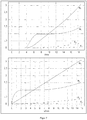
- FIG. 7 shows in two diagrams the processes of the horizontal portions of path N s (path portion cams), F s (distance share conveyed) and speed N v (speed share cams), F v (speed share conveyed) of the stop cam and the conveyed material as a function of time and cam lift ,
- the advance of the cam can be seen from the characteristics of the material to be conveyed and cam, since these characteristics do not intersect after the start of the movement.
- Both the horizontal path portion, as well as the speed of the stop cam are considerably higher depending on the time, as well as in dependence of the path compared to the respective characteristics of the conveyed material 1. This effect is achieved by means of the inclination of the stop cam 3 by 12 °.
Landscapes
- Engineering & Computer Science (AREA)
- Mechanical Engineering (AREA)
- Special Conveying (AREA)
Claims (8)
- Dispositif pour arrêter un produit transporté sur un convoyeur, présentant un arrêt (S) avec une came (3) pour arrêter un produit transporté (1), la came (3) pouvant être déplacée le long d'un axe (A) dans une position angulaire d'un angle (β) par rapport à une perpendiculaire à la direction de déplacement du produit transporté (1) se trouvant sur le convoyeur et pouvant être actionnée au moyen d'un entraînement,
caractérisé en ce que- un moyen d'amortissement (D) qui peut être relié à l'arrêt (S) est formé séparément de l'arrêt (S),- l'arrêt (S) étant en liaison fonctionnelle avec le moyen d'amortissement (D) et l'arrêt (S) étant mobile parallèlement au convoyeur (2) dans la direction du moyen d'amortissement (D) lorsque le produit transporté (1) bute contre lui et- le moyen d'amortissement (D) présentant un amortisseur (9) et un levier (6), lequel levier (6) peut être actionné par le produit transporté (1) passant dessus de telle sorte que le moyen d'amortissement (D) et l'amortisseur (9) peuvent être amenés dans leur position initiale par le levier (6). - Dispositif selon la revendication 1, caractérisé en ce que l'entraînement (5) est réalisé sous la forme d'un aimant de levage réversible à actionnement électrique.
- Dispositif selon la revendication 1 ou 2, caractérisé en ce que l'entraînement (5) se raccorde directement à un guide linéaire (4) de l'arrêt (S) ou en ce que l'entraînement (5) est intégré dans le guide linéaire (4) de l'arrêt.
- Dispositif selon l'une des revendications 1 à 3, caractérisé en ce que l'entraînement (5) est relié directement à la came (3) par une tige d'actionnement (5.1) ou en ce que la came (3) est formée directement sur la tige d'actionnement (5.1) de l'entraînement (5) de telle sorte que le mouvement de réglage linéaire de l'entraînement (5) peut être transmis directement à la came (3).
- Dispositif selon l'une des revendications 1 à 4, caractérisé en ce que la came (3) présente grâce à l'entraînement (5) une accélération d'au moins 300 m/s2 et une vitesse d'au moins 1 m/s.
- Dispositif selon l'une des revendications 1 à 5, caractérisé en ce que l'entraînement (5) sous la forme d'un aimant de levage réversible à magnétisation permanente présente à l'état sans courant des forces de maintien élevées dans sa position finale.
- Dispositif selon la revendication 1, caractérisé en ce que l'amortisseur s'étend parallèlement au convoyeur (2), l'amortisseur (9) pouvant être comprimé lorsque le produit transporté (1) bute contre l'arrêt électrique (S).
- Dispositif selon l'une des revendications 1 à 7, caractérisé en ce que l'arrêt (S) est monté sur un chariot (8) de manière déplaçable parallèlement au convoyeur (2) dans la direction du moyen d'amortissement (D).
Applications Claiming Priority (2)
| Application Number | Priority Date | Filing Date | Title |
|---|---|---|---|
| DE102016110400.0A DE102016110400A1 (de) | 2016-06-06 | 2016-06-06 | Vorrichtung zum Stoppen eines Fördergutes auf einem Förderer |
| DE202017103367.8U DE202017103367U1 (de) | 2017-06-02 | 2017-06-02 | Vorrichtung zum Stoppen eines Fördergutes auf einem Förderer |
Publications (2)
| Publication Number | Publication Date |
|---|---|
| EP3254997A1 EP3254997A1 (fr) | 2017-12-13 |
| EP3254997B1 true EP3254997B1 (fr) | 2019-03-06 |
Family
ID=59053931
Family Applications (1)
| Application Number | Title | Priority Date | Filing Date |
|---|---|---|---|
| EP17174516.9A Active EP3254997B1 (fr) | 2016-06-06 | 2017-06-06 | Dispositif d'arrêt d'une marchandise à transporter sur un convoyeur |
Country Status (1)
| Country | Link |
|---|---|
| EP (1) | EP3254997B1 (fr) |
Families Citing this family (1)
| Publication number | Priority date | Publication date | Assignee | Title |
|---|---|---|---|---|
| CN108974908A (zh) * | 2018-07-27 | 2018-12-11 | 东莞市联洲知识产权运营管理有限公司 | 一种继电器包装装置上的保护罩输送结构 |
Family Cites Families (10)
| Publication number | Priority date | Publication date | Assignee | Title |
|---|---|---|---|---|
| US3532201A (en) * | 1968-09-23 | 1970-10-06 | Interlake Steel Corp | Conveyor load spacer |
| SE442623B (sv) * | 1985-03-05 | 1986-01-20 | Skf Nova Ab | In- och urkopplingsbar sperranordning for pa en transportbana transporterade objekt |
| JPH0261825U (fr) * | 1988-10-25 | 1990-05-09 | ||
| DE8906202U1 (de) * | 1989-05-19 | 1989-09-07 | Heinrich Niederberger KG, 8172 Lenggries | Auflaufeinrichtung |
| JPH07112822A (ja) * | 1993-10-18 | 1995-05-02 | Murata Mach Ltd | ローラコンベアにおける被搬送物の停止装置 |
| JPH07267359A (ja) * | 1994-03-25 | 1995-10-17 | Nippon Steel Corp | 鋼板停止装置における過負荷キャンセル機構 |
| JPH08108931A (ja) * | 1994-10-12 | 1996-04-30 | Murata Mach Ltd | ストッパ装置 |
| FR2729936B1 (fr) * | 1995-01-30 | 1997-04-18 | Sipa Roller | Systeme de securite pour dispositif de separation des charges dans un couloir de stockage dynamique |
| DE102006028493A1 (de) * | 2006-06-21 | 2007-12-27 | KRUPS Fördersysteme GmbH | Anhaltevorrichtung |
| WO2009063562A1 (fr) * | 2007-11-15 | 2009-05-22 | Hirata Corporation | Dispositif de transport de substrat |
-
2017
- 2017-06-06 EP EP17174516.9A patent/EP3254997B1/fr active Active
Non-Patent Citations (1)
| Title |
|---|
| None * |
Also Published As
| Publication number | Publication date |
|---|---|
| EP3254997A1 (fr) | 2017-12-13 |
Similar Documents
| Publication | Publication Date | Title |
|---|---|---|
| DE102014017094B4 (de) | Servosteuervorrichtung mit Funktion zur Verringerung des Absenkens bei einem Bremsvorgang | |
| DE102017212660A1 (de) | Saugvorrichtung | |
| EP1902981B1 (fr) | Module butée | |
| DE102013202674A1 (de) | Transportvorrichtung zur Förderung eines Produkts | |
| EP3254997B1 (fr) | Dispositif d'arrêt d'une marchandise à transporter sur un convoyeur | |
| EP3096899A1 (fr) | Dispositif d'assemblage, de préférence de rivetage, clinchage ou poinçonnage | |
| DE202017103367U1 (de) | Vorrichtung zum Stoppen eines Fördergutes auf einem Förderer | |
| DE102018124772A1 (de) | Anschlagmodul zum positionsgenauen Abbremsen und/oder Anhalten eines Gegenstands | |
| DE102016110400A1 (de) | Vorrichtung zum Stoppen eines Fördergutes auf einem Förderer | |
| EP1900669B1 (fr) | Dispositif destiné au positionnement d'une arête arrière de feuille | |
| EP2455208B1 (fr) | Dispositif et procédé pour amortissement d'un système de levage du fond de moule | |
| DE2949745A1 (de) | Werkstuecktransportvorrichtung | |
| DE102011122492A1 (de) | Presse zur Werkstückbearbeitung | |
| DE102012103820B3 (de) | Anschlagmodul zum positionsgenauen Anhalten eines Gegenstandes | |
| DE10304021B4 (de) | Vorrichtung zum Ausrichten von Bogen im Ausleger einer bogenverarbeitenden Maschine | |
| EP1514813B1 (fr) | Dispositif de stockage d'articles de type rouleau | |
| DE2812973C2 (de) | Einrichtung zur Dämpfung des Schnittschlages an einer hydraulischen Presse | |
| EP1354835B1 (fr) | Dispositif d'entraínement pour une lame de pliage | |
| DE102006003851A1 (de) | Vorrichtung zum Formen, Stanzen und Stapeln von tiefgezogenen Teilen aus thermoplastischen Kunststoffen | |
| WO2016091767A1 (fr) | Dispositif d'arrêt pour récipients ainsi que procédé pour le freinage, l'arrêt et la séparation commandés de récipients | |
| DE102007057228A1 (de) | Vorrichtung zum Überführen einer Buchdecke von einer Anrolleinrichtung zu einer Übergabestelle | |
| DE102007041387A1 (de) | Bremsvorrichtung für eine Cockpittür zum Bremsen im Dekompressionsfall | |
| DE1927559B2 (de) | Stößelendschalter mit begrenztem Schwenkwinkel | |
| DE2348114C3 (de) | Sicherheitsklappe für Raumentlüftungen | |
| DE959662C (de) | Anordnung zur elektromotorischen Betaetigung von Schaltern, bei welcher die zur Schalterbetaetigung erforderliche Energie von einem Fliehkraftsystem geliefert wird |
Legal Events
| Date | Code | Title | Description |
|---|---|---|---|
| PUAI | Public reference made under article 153(3) epc to a published international application that has entered the european phase |
Free format text: ORIGINAL CODE: 0009012 |
|
| STAA | Information on the status of an ep patent application or granted ep patent |
Free format text: STATUS: THE APPLICATION HAS BEEN PUBLISHED |
|
| AK | Designated contracting states |
Kind code of ref document: A1 Designated state(s): AL AT BE BG CH CY CZ DE DK EE ES FI FR GB GR HR HU IE IS IT LI LT LU LV MC MK MT NL NO PL PT RO RS SE SI SK SM TR |
|
| AX | Request for extension of the european patent |
Extension state: BA ME |
|
| STAA | Information on the status of an ep patent application or granted ep patent |
Free format text: STATUS: REQUEST FOR EXAMINATION WAS MADE |
|
| 17P | Request for examination filed |
Effective date: 20180129 |
|
| RBV | Designated contracting states (corrected) |
Designated state(s): AL AT BE BG CH CY CZ DE DK EE ES FI FR GB GR HR HU IE IS IT LI LT LU LV MC MK MT NL NO PL PT RO RS SE SI SK SM TR |
|
| GRAP | Despatch of communication of intention to grant a patent |
Free format text: ORIGINAL CODE: EPIDOSNIGR1 |
|
| STAA | Information on the status of an ep patent application or granted ep patent |
Free format text: STATUS: GRANT OF PATENT IS INTENDED |
|
| INTG | Intention to grant announced |
Effective date: 20180920 |
|
| GRAS | Grant fee paid |
Free format text: ORIGINAL CODE: EPIDOSNIGR3 |
|
| GRAA | (expected) grant |
Free format text: ORIGINAL CODE: 0009210 |
|
| STAA | Information on the status of an ep patent application or granted ep patent |
Free format text: STATUS: THE PATENT HAS BEEN GRANTED |
|
| AK | Designated contracting states |
Kind code of ref document: B1 Designated state(s): AL AT BE BG CH CY CZ DE DK EE ES FI FR GB GR HR HU IE IS IT LI LT LU LV MC MK MT NL NO PL PT RO RS SE SI SK SM TR |
|
| REG | Reference to a national code |
Ref country code: GB Ref legal event code: FG4D Free format text: NOT ENGLISH |
|
| REG | Reference to a national code |
Ref country code: CH Ref legal event code: EP Ref country code: AT Ref legal event code: REF Ref document number: 1104247 Country of ref document: AT Kind code of ref document: T Effective date: 20190315 |
|
| REG | Reference to a national code |
Ref country code: DE Ref legal event code: R096 Ref document number: 502017000871 Country of ref document: DE |
|
| REG | Reference to a national code |
Ref country code: IE Ref legal event code: FG4D Free format text: LANGUAGE OF EP DOCUMENT: GERMAN |
|
| REG | Reference to a national code |
Ref country code: NL Ref legal event code: MP Effective date: 20190306 |
|
| REG | Reference to a national code |
Ref country code: LT Ref legal event code: MG4D |
|
| PG25 | Lapsed in a contracting state [announced via postgrant information from national office to epo] |
Ref country code: FI Free format text: LAPSE BECAUSE OF FAILURE TO SUBMIT A TRANSLATION OF THE DESCRIPTION OR TO PAY THE FEE WITHIN THE PRESCRIBED TIME-LIMIT Effective date: 20190306 Ref country code: NO Free format text: LAPSE BECAUSE OF FAILURE TO SUBMIT A TRANSLATION OF THE DESCRIPTION OR TO PAY THE FEE WITHIN THE PRESCRIBED TIME-LIMIT Effective date: 20190606 Ref country code: LT Free format text: LAPSE BECAUSE OF FAILURE TO SUBMIT A TRANSLATION OF THE DESCRIPTION OR TO PAY THE FEE WITHIN THE PRESCRIBED TIME-LIMIT Effective date: 20190306 Ref country code: SE Free format text: LAPSE BECAUSE OF FAILURE TO SUBMIT A TRANSLATION OF THE DESCRIPTION OR TO PAY THE FEE WITHIN THE PRESCRIBED TIME-LIMIT Effective date: 20190306 |
|
| PG25 | Lapsed in a contracting state [announced via postgrant information from national office to epo] |
Ref country code: LV Free format text: LAPSE BECAUSE OF FAILURE TO SUBMIT A TRANSLATION OF THE DESCRIPTION OR TO PAY THE FEE WITHIN THE PRESCRIBED TIME-LIMIT Effective date: 20190306 Ref country code: NL Free format text: LAPSE BECAUSE OF FAILURE TO SUBMIT A TRANSLATION OF THE DESCRIPTION OR TO PAY THE FEE WITHIN THE PRESCRIBED TIME-LIMIT Effective date: 20190306 Ref country code: RS Free format text: LAPSE BECAUSE OF FAILURE TO SUBMIT A TRANSLATION OF THE DESCRIPTION OR TO PAY THE FEE WITHIN THE PRESCRIBED TIME-LIMIT Effective date: 20190306 Ref country code: BG Free format text: LAPSE BECAUSE OF FAILURE TO SUBMIT A TRANSLATION OF THE DESCRIPTION OR TO PAY THE FEE WITHIN THE PRESCRIBED TIME-LIMIT Effective date: 20190606 Ref country code: GR Free format text: LAPSE BECAUSE OF FAILURE TO SUBMIT A TRANSLATION OF THE DESCRIPTION OR TO PAY THE FEE WITHIN THE PRESCRIBED TIME-LIMIT Effective date: 20190607 Ref country code: HR Free format text: LAPSE BECAUSE OF FAILURE TO SUBMIT A TRANSLATION OF THE DESCRIPTION OR TO PAY THE FEE WITHIN THE PRESCRIBED TIME-LIMIT Effective date: 20190306 |
|
| PG25 | Lapsed in a contracting state [announced via postgrant information from national office to epo] |
Ref country code: EE Free format text: LAPSE BECAUSE OF FAILURE TO SUBMIT A TRANSLATION OF THE DESCRIPTION OR TO PAY THE FEE WITHIN THE PRESCRIBED TIME-LIMIT Effective date: 20190306 Ref country code: AL Free format text: LAPSE BECAUSE OF FAILURE TO SUBMIT A TRANSLATION OF THE DESCRIPTION OR TO PAY THE FEE WITHIN THE PRESCRIBED TIME-LIMIT Effective date: 20190306 Ref country code: SK Free format text: LAPSE BECAUSE OF FAILURE TO SUBMIT A TRANSLATION OF THE DESCRIPTION OR TO PAY THE FEE WITHIN THE PRESCRIBED TIME-LIMIT Effective date: 20190306 Ref country code: PT Free format text: LAPSE BECAUSE OF FAILURE TO SUBMIT A TRANSLATION OF THE DESCRIPTION OR TO PAY THE FEE WITHIN THE PRESCRIBED TIME-LIMIT Effective date: 20190706 Ref country code: CZ Free format text: LAPSE BECAUSE OF FAILURE TO SUBMIT A TRANSLATION OF THE DESCRIPTION OR TO PAY THE FEE WITHIN THE PRESCRIBED TIME-LIMIT Effective date: 20190306 Ref country code: IT Free format text: LAPSE BECAUSE OF FAILURE TO SUBMIT A TRANSLATION OF THE DESCRIPTION OR TO PAY THE FEE WITHIN THE PRESCRIBED TIME-LIMIT Effective date: 20190306 Ref country code: ES Free format text: LAPSE BECAUSE OF FAILURE TO SUBMIT A TRANSLATION OF THE DESCRIPTION OR TO PAY THE FEE WITHIN THE PRESCRIBED TIME-LIMIT Effective date: 20190306 Ref country code: RO Free format text: LAPSE BECAUSE OF FAILURE TO SUBMIT A TRANSLATION OF THE DESCRIPTION OR TO PAY THE FEE WITHIN THE PRESCRIBED TIME-LIMIT Effective date: 20190306 |
|
| PG25 | Lapsed in a contracting state [announced via postgrant information from national office to epo] |
Ref country code: SM Free format text: LAPSE BECAUSE OF FAILURE TO SUBMIT A TRANSLATION OF THE DESCRIPTION OR TO PAY THE FEE WITHIN THE PRESCRIBED TIME-LIMIT Effective date: 20190306 Ref country code: PL Free format text: LAPSE BECAUSE OF FAILURE TO SUBMIT A TRANSLATION OF THE DESCRIPTION OR TO PAY THE FEE WITHIN THE PRESCRIBED TIME-LIMIT Effective date: 20190306 |
|
| REG | Reference to a national code |
Ref country code: DE Ref legal event code: R097 Ref document number: 502017000871 Country of ref document: DE |
|
| PG25 | Lapsed in a contracting state [announced via postgrant information from national office to epo] |
Ref country code: IS Free format text: LAPSE BECAUSE OF FAILURE TO SUBMIT A TRANSLATION OF THE DESCRIPTION OR TO PAY THE FEE WITHIN THE PRESCRIBED TIME-LIMIT Effective date: 20190706 |
|
| PLBE | No opposition filed within time limit |
Free format text: ORIGINAL CODE: 0009261 |
|
| STAA | Information on the status of an ep patent application or granted ep patent |
Free format text: STATUS: NO OPPOSITION FILED WITHIN TIME LIMIT |
|
| PG25 | Lapsed in a contracting state [announced via postgrant information from national office to epo] |
Ref country code: DK Free format text: LAPSE BECAUSE OF FAILURE TO SUBMIT A TRANSLATION OF THE DESCRIPTION OR TO PAY THE FEE WITHIN THE PRESCRIBED TIME-LIMIT Effective date: 20190306 Ref country code: MC Free format text: LAPSE BECAUSE OF FAILURE TO SUBMIT A TRANSLATION OF THE DESCRIPTION OR TO PAY THE FEE WITHIN THE PRESCRIBED TIME-LIMIT Effective date: 20190306 |
|
| 26N | No opposition filed |
Effective date: 20191209 |
|
| PG25 | Lapsed in a contracting state [announced via postgrant information from national office to epo] |
Ref country code: SI Free format text: LAPSE BECAUSE OF FAILURE TO SUBMIT A TRANSLATION OF THE DESCRIPTION OR TO PAY THE FEE WITHIN THE PRESCRIBED TIME-LIMIT Effective date: 20190306 |
|
| REG | Reference to a national code |
Ref country code: BE Ref legal event code: MM Effective date: 20190630 |
|
| PG25 | Lapsed in a contracting state [announced via postgrant information from national office to epo] |
Ref country code: TR Free format text: LAPSE BECAUSE OF FAILURE TO SUBMIT A TRANSLATION OF THE DESCRIPTION OR TO PAY THE FEE WITHIN THE PRESCRIBED TIME-LIMIT Effective date: 20190306 |
|
| PG25 | Lapsed in a contracting state [announced via postgrant information from national office to epo] |
Ref country code: IE Free format text: LAPSE BECAUSE OF NON-PAYMENT OF DUE FEES Effective date: 20190606 |
|
| PG25 | Lapsed in a contracting state [announced via postgrant information from national office to epo] |
Ref country code: BE Free format text: LAPSE BECAUSE OF NON-PAYMENT OF DUE FEES Effective date: 20190630 Ref country code: LU Free format text: LAPSE BECAUSE OF NON-PAYMENT OF DUE FEES Effective date: 20190606 |
|
| PG25 | Lapsed in a contracting state [announced via postgrant information from national office to epo] |
Ref country code: FR Free format text: LAPSE BECAUSE OF NON-PAYMENT OF DUE FEES Effective date: 20190630 |
|
| PG25 | Lapsed in a contracting state [announced via postgrant information from national office to epo] |
Ref country code: CY Free format text: LAPSE BECAUSE OF FAILURE TO SUBMIT A TRANSLATION OF THE DESCRIPTION OR TO PAY THE FEE WITHIN THE PRESCRIBED TIME-LIMIT Effective date: 20190306 |
|
| PG25 | Lapsed in a contracting state [announced via postgrant information from national office to epo] |
Ref country code: MT Free format text: LAPSE BECAUSE OF FAILURE TO SUBMIT A TRANSLATION OF THE DESCRIPTION OR TO PAY THE FEE WITHIN THE PRESCRIBED TIME-LIMIT Effective date: 20190306 Ref country code: HU Free format text: LAPSE BECAUSE OF FAILURE TO SUBMIT A TRANSLATION OF THE DESCRIPTION OR TO PAY THE FEE WITHIN THE PRESCRIBED TIME-LIMIT; INVALID AB INITIO Effective date: 20170606 |
|
| GBPC | Gb: european patent ceased through non-payment of renewal fee |
Effective date: 20210606 |
|
| PG25 | Lapsed in a contracting state [announced via postgrant information from national office to epo] |
Ref country code: GB Free format text: LAPSE BECAUSE OF NON-PAYMENT OF DUE FEES Effective date: 20210606 |
|
| PG25 | Lapsed in a contracting state [announced via postgrant information from national office to epo] |
Ref country code: MK Free format text: LAPSE BECAUSE OF FAILURE TO SUBMIT A TRANSLATION OF THE DESCRIPTION OR TO PAY THE FEE WITHIN THE PRESCRIBED TIME-LIMIT Effective date: 20190306 |
|
| PGFP | Annual fee paid to national office [announced via postgrant information from national office to epo] |
Ref country code: CH Payment date: 20220629 Year of fee payment: 6 |
|
| REG | Reference to a national code |
Ref country code: AT Ref legal event code: MM01 Ref document number: 1104247 Country of ref document: AT Kind code of ref document: T Effective date: 20220606 |
|
| PG25 | Lapsed in a contracting state [announced via postgrant information from national office to epo] |
Ref country code: AT Free format text: LAPSE BECAUSE OF NON-PAYMENT OF DUE FEES Effective date: 20220606 |
|
| REG | Reference to a national code |
Ref country code: CH Ref legal event code: PL |
|
| PG25 | Lapsed in a contracting state [announced via postgrant information from national office to epo] |
Ref country code: CH Free format text: LAPSE BECAUSE OF NON-PAYMENT OF DUE FEES Effective date: 20230630 |
|
| PGFP | Annual fee paid to national office [announced via postgrant information from national office to epo] |
Ref country code: DE Payment date: 20250410 Year of fee payment: 9 |