EP3255201B1 - Condenseur à air et machine à sécher le linge - Google Patents
Condenseur à air et machine à sécher le linge Download PDFInfo
- Publication number
- EP3255201B1 EP3255201B1 EP15880861.8A EP15880861A EP3255201B1 EP 3255201 B1 EP3255201 B1 EP 3255201B1 EP 15880861 A EP15880861 A EP 15880861A EP 3255201 B1 EP3255201 B1 EP 3255201B1
- Authority
- EP
- European Patent Office
- Prior art keywords
- air
- ducts
- condensing
- group
- condenser
- Prior art date
- Legal status (The legal status is an assumption and is not a legal conclusion. Google has not performed a legal analysis and makes no representation as to the accuracy of the status listed.)
- Active
Links
Images


Classifications
-
- D—TEXTILES; PAPER
- D06—TREATMENT OF TEXTILES OR THE LIKE; LAUNDERING; FLEXIBLE MATERIALS NOT OTHERWISE PROVIDED FOR
- D06F—LAUNDERING, DRYING, IRONING, PRESSING OR FOLDING TEXTILE ARTICLES
- D06F58/00—Domestic laundry dryers
- D06F58/20—General details of domestic laundry dryers
- D06F58/24—Condensing arrangements
-
- D—TEXTILES; PAPER
- D06—TREATMENT OF TEXTILES OR THE LIKE; LAUNDERING; FLEXIBLE MATERIALS NOT OTHERWISE PROVIDED FOR
- D06F—LAUNDERING, DRYING, IRONING, PRESSING OR FOLDING TEXTILE ARTICLES
- D06F58/00—Domestic laundry dryers
- D06F58/10—Drying cabinets or drying chambers having heating or ventilating means
-
- D—TEXTILES; PAPER
- D06—TREATMENT OF TEXTILES OR THE LIKE; LAUNDERING; FLEXIBLE MATERIALS NOT OTHERWISE PROVIDED FOR
- D06F—LAUNDERING, DRYING, IRONING, PRESSING OR FOLDING TEXTILE ARTICLES
- D06F58/00—Domestic laundry dryers
- D06F58/20—General details of domestic laundry dryers
- D06F58/206—Heat pump arrangements
-
- F—MECHANICAL ENGINEERING; LIGHTING; HEATING; WEAPONS; BLASTING
- F28—HEAT EXCHANGE IN GENERAL
- F28D—HEAT-EXCHANGE APPARATUS, NOT PROVIDED FOR IN ANOTHER SUBCLASS, IN WHICH THE HEAT-EXCHANGE MEDIA DO NOT COME INTO DIRECT CONTACT
- F28D1/00—Heat-exchange apparatus having stationary conduit assemblies for one heat-exchange medium only, the media being in contact with different sides of the conduit wall, in which the other heat-exchange medium is a large body of fluid, e.g. domestic or motor car radiators
- F28D1/02—Heat-exchange apparatus having stationary conduit assemblies for one heat-exchange medium only, the media being in contact with different sides of the conduit wall, in which the other heat-exchange medium is a large body of fluid, e.g. domestic or motor car radiators with heat-exchange conduits immersed in the body of fluid
- F28D1/04—Heat-exchange apparatus having stationary conduit assemblies for one heat-exchange medium only, the media being in contact with different sides of the conduit wall, in which the other heat-exchange medium is a large body of fluid, e.g. domestic or motor car radiators with heat-exchange conduits immersed in the body of fluid with tubular conduits
-
- F—MECHANICAL ENGINEERING; LIGHTING; HEATING; WEAPONS; BLASTING
- F28—HEAT EXCHANGE IN GENERAL
- F28D—HEAT-EXCHANGE APPARATUS, NOT PROVIDED FOR IN ANOTHER SUBCLASS, IN WHICH THE HEAT-EXCHANGE MEDIA DO NOT COME INTO DIRECT CONTACT
- F28D21/00—Heat-exchange apparatus not covered by any of the groups F28D1/00 - F28D20/00
- F28D21/0001—Recuperative heat exchangers
- F28D21/0014—Recuperative heat exchangers the heat being recuperated from waste air or from vapors
-
- F—MECHANICAL ENGINEERING; LIGHTING; HEATING; WEAPONS; BLASTING
- F28—HEAT EXCHANGE IN GENERAL
- F28D—HEAT-EXCHANGE APPARATUS, NOT PROVIDED FOR IN ANOTHER SUBCLASS, IN WHICH THE HEAT-EXCHANGE MEDIA DO NOT COME INTO DIRECT CONTACT
- F28D7/00—Heat-exchange apparatus having stationary tubular conduit assemblies for both heat-exchange media, the media being in contact with different sides of a conduit wall
- F28D7/08—Heat-exchange apparatus having stationary tubular conduit assemblies for both heat-exchange media, the media being in contact with different sides of a conduit wall the conduits being otherwise bent, e.g. in a serpentine or zig-zag
- F28D7/082—Heat-exchange apparatus having stationary tubular conduit assemblies for both heat-exchange media, the media being in contact with different sides of a conduit wall the conduits being otherwise bent, e.g. in a serpentine or zig-zag with serpentine or zig-zag configuration
- F28D7/085—Heat-exchange apparatus having stationary tubular conduit assemblies for both heat-exchange media, the media being in contact with different sides of a conduit wall the conduits being otherwise bent, e.g. in a serpentine or zig-zag with serpentine or zig-zag configuration in the form of parallel conduits coupled by bent portions
- F28D7/087—Heat-exchange apparatus having stationary tubular conduit assemblies for both heat-exchange media, the media being in contact with different sides of a conduit wall the conduits being otherwise bent, e.g. in a serpentine or zig-zag with serpentine or zig-zag configuration in the form of parallel conduits coupled by bent portions assembled in arrays, each array being arranged in the same plane
-
- F—MECHANICAL ENGINEERING; LIGHTING; HEATING; WEAPONS; BLASTING
- F28—HEAT EXCHANGE IN GENERAL
- F28D—HEAT-EXCHANGE APPARATUS, NOT PROVIDED FOR IN ANOTHER SUBCLASS, IN WHICH THE HEAT-EXCHANGE MEDIA DO NOT COME INTO DIRECT CONTACT
- F28D9/00—Heat-exchange apparatus having stationary plate-like or laminated conduit assemblies for both heat-exchange media, the media being in contact with different sides of a conduit wall
- F28D9/0093—Multi-circuit heat-exchangers, e.g. integrating different heat exchange sections in the same unit or heat-exchangers for more than two fluids
-
- F—MECHANICAL ENGINEERING; LIGHTING; HEATING; WEAPONS; BLASTING
- F28—HEAT EXCHANGE IN GENERAL
- F28F—DETAILS OF HEAT-EXCHANGE AND HEAT-TRANSFER APPARATUS, OF GENERAL APPLICATION
- F28F9/00—Casings; Header boxes; Auxiliary supports for elements; Auxiliary members within casings
- F28F9/02—Header boxes; End plates
-
- D—TEXTILES; PAPER
- D06—TREATMENT OF TEXTILES OR THE LIKE; LAUNDERING; FLEXIBLE MATERIALS NOT OTHERWISE PROVIDED FOR
- D06F—LAUNDERING, DRYING, IRONING, PRESSING OR FOLDING TEXTILE ARTICLES
- D06F2103/00—Parameters monitored or detected for the control of domestic laundry washing machines, washer-dryers or laundry dryers
- D06F2103/56—Parameters monitored or detected for the control of domestic laundry washing machines, washer-dryers or laundry dryers related to air ducts, e.g. position of flow diverters
-
- D—TEXTILES; PAPER
- D06—TREATMENT OF TEXTILES OR THE LIKE; LAUNDERING; FLEXIBLE MATERIALS NOT OTHERWISE PROVIDED FOR
- D06F—LAUNDERING, DRYING, IRONING, PRESSING OR FOLDING TEXTILE ARTICLES
- D06F2105/00—Systems or parameters controlled or affected by the control systems of washing machines, washer-dryers or laundry dryers
- D06F2105/28—Electric heating
-
- D—TEXTILES; PAPER
- D06—TREATMENT OF TEXTILES OR THE LIKE; LAUNDERING; FLEXIBLE MATERIALS NOT OTHERWISE PROVIDED FOR
- D06F—LAUNDERING, DRYING, IRONING, PRESSING OR FOLDING TEXTILE ARTICLES
- D06F2105/00—Systems or parameters controlled or affected by the control systems of washing machines, washer-dryers or laundry dryers
- D06F2105/30—Blowers
-
- D—TEXTILES; PAPER
- D06—TREATMENT OF TEXTILES OR THE LIKE; LAUNDERING; FLEXIBLE MATERIALS NOT OTHERWISE PROVIDED FOR
- D06F—LAUNDERING, DRYING, IRONING, PRESSING OR FOLDING TEXTILE ARTICLES
- D06F58/00—Domestic laundry dryers
- D06F58/20—General details of domestic laundry dryers
-
- F—MECHANICAL ENGINEERING; LIGHTING; HEATING; WEAPONS; BLASTING
- F28—HEAT EXCHANGE IN GENERAL
- F28D—HEAT-EXCHANGE APPARATUS, NOT PROVIDED FOR IN ANOTHER SUBCLASS, IN WHICH THE HEAT-EXCHANGE MEDIA DO NOT COME INTO DIRECT CONTACT
- F28D21/00—Heat-exchange apparatus not covered by any of the groups F28D1/00 - F28D20/00
- F28D2021/0019—Other heat exchangers for particular applications; Heat exchange systems not otherwise provided for
- F28D2021/0038—Other heat exchangers for particular applications; Heat exchange systems not otherwise provided for for drying or dehumidifying gases or vapours
Definitions
- the present invention relates to the field of clothes drying apparatuses, and particularly relates to an air condenser applied to a clothes dryer and a clothes dryer with the air condenser.
- a condenser adopted by a clothes dryer in a market is generally a cross-type air heat exchanger, and the cross-type air heat exchanger only has a single condensing air duct and a single cooling air duct arranged crosswise.
- air inlet heat in the condensing air duct is not fully utilized, so heat efficiency is low, and energy loss is great.
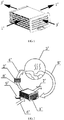
- FIG. 1 and Fig. 2 show schematic diagrams of a structure of the cross-type air heat exchanger and an internal air flowing direction of the cross-type air heat exchanger.
- An operating principle of a traditional condenser applied to the clothes dryer is as follows: in a using process of the clothes dryer, an air duct passing through a traditional condensation-type clothes dryer is divided into a condensing air duct j' and a cooling air duct i', the cooling air duct i' is a non-closed-loop duct; and air is sucked into the clothes dryer by a fan, subjected to heat exchange on an inner surface of an air condenser 1', heated after heat exchange and then discharged out of the air condenser 1' via an outlet of the cooling air duct.
- the condensing air duct j' is a closed air duct; the air is circularly operated in the condensing air duct j' formed among components such as a drum 3' of the clothes dryer, the air condenser 1', a heater 2' and the like; saturated hot air 5' in the drum 3' before passing through the air condenser is sucked into the air condenser 1' by the fan and is subjected to heat exchange on the inner surface of an air condenser 1'; moisture in the saturated hot air 5' before passing through the air condenser is condensed into condensate water 9' and discharged out of the air condenser 1'; unsaturated hot air 8' discharged out of the air condenser 1' is heated by the heater 2' to become hot dry air 4'; the hot dry air enters the drum 3' of the clothes dryer and is fully contacted with clothes; the moisture on surfaces of the clothes is evaporated into water vapor; and the water vapor is sucked into the air con
- a flowing direction of the air in the cooling air duct i' is as follows: room-temperature dry air 6' before passing through the air condenser enters the air condenser 1', performs heat exchange with the saturated hot air 5' before passing through the air condenser to become hot dry air 7', and is discharged out of the air condenser 1'. Since heat carried by the hot air discharged from the condenser in the cooling air duct i' of the clothes dryer adopting the traditional condenser above is lost, heat is greatly wasted.
- the condenser can recycle the heat of the hot air with water vapor cooled by the condensing air duct for preheating low-temperature air discharged to a heating element and having no water vapor, thereby achieving an effect of saving energy.
- CN102517861A discloses a clothes drying temperature detection control method and a clothes drier.
- a control system is used for detecting a change delta T of temperature of outgoing air in front and in rear of a condenser after drying, and determines whether the change of temperature difference of outgoing air before or after passing the condenser reaches a corresponding set value delta Tt_g or not; g is the weight of clothes to be dried; if the delta T is larger than or equal to the delta Tt_g or lasts for a set time T within a certain set value range, the clothes are dried and a heating device stops operating; after the heating device stops operating, a drying program proceeds and does not end until the detected temperature of incoming air is lower than the set temperature; and in the process of drying, heat of humid hot air after being subjected to heat exchange with clothes and before being subjected to cooling and dehumidification is subjected to heat exchange with air which is subjected to condensation and dehumidification, and the prehe
- EP1939571A2 discloses that a heat exchange element of a heat exchanger prevents losses due to internal pressure non-uniformity.
- the heat exchanger includes a plurality of heat exchange sheets (3, 211, 212) which are stacked together.
- a plurality of airflow guide ribs (4, 5,212a,212b,212c) located between the sheets (3,211,212) have connection passages (40,50) that allow gases to flow between adjacent ducts.
- the flow of gasses through the connection passages (40,50) offsets pressure non-uniformity between adjacent ducts.
- the ribs can be continuously arranged over the length of the heat exchange ducts to increase an area supporting the heat exchange sheets, and thus the sag phenomenon of the heat exchange sheet can be prevented.
- a purpose of the present invention is to propose an air condenser for solving problems in an existing art that heat of hot air is seriously wasted and heat exchange efficiency is low in a using process of a cross-type heat exchanger.
- Another purpose of the present invention is to propose a clothes dryer.
- the air condenser above is arranged on the clothes dryer, so that the clothes dryer is small in energy loss and high in heat exchange efficiency in a using process.
- an air condenser that includes condensing air ducts and a cooling pipeline arranged crosswise, wherein the condensing air ducts include a first group of condensing air ducts and a second group of condensing air ducts; air inlet ducts of the first group of condensing air ducts and air outlet ducts of the second group of condensing air ducts are at least partially arranged in a heat exchangeable manner; and air outlet ducts of the first group of condensing air ducts and air inlet ducts of the second group of condensing air ducts are at least partially arranged in a heat exchangeable manner.
- the condensing air ducts include intermediate air ducts, wherein at least one part of the intermediate air ducts is connected between the air inlet ducts and the air outlet ducts of the first group of condensing air ducts; at least another part of the intermediate air ducts is connected between the air inlet ducts and the air outlet ducts of the second group of condensing air ducts; and the intermediate air ducts and the cooling pipeline are arranged crosswise to perform heat exchange.
- the first group of condensing air ducts include at least one first condensing sheet; and the first condensing sheet is formed with at least the air inlet ducts and the air outlet ducts of the first condensing air ducts;
- the second group of condensing air ducts include at least one second condensing sheet; and the second condensing sheet is formed with at least the air inlet ducts and the air outlet ducts of the second condensing air ducts;
- the first condensing sheet and the second condensing sheet are arranged at intervals, so that the air inlet ducts of the first condensing air ducts and the air outlet ducts of the second condensing air ducts are arranged adjacently, and projections of the air inlet ducts of the first condensing air ducts and the air outlet ducts of the second condensing air ducts are at least partially overlapped; and the air outlet ducts of the first condens
- intermediate air ducts and the air inlet ducts and the air outlet ducts of the first group of condensing air ducts and the second group of condensing air ducts are formed integrally or separately.
- cooling pipeline is used for introducing low-temperature gas or liquid.
- the air condenser further includes four interfaces, respectively connected with the air inlet ducts of the first group of condensing air ducts, the air outlet ducts of the first group of condensing air ducts, the air inlet ducts of the second group of condensing air ducts and the air outlet ducts of the second group of condensing air ducts.
- a clothes dryer that includes a drum and a heater, wherein the above air condenser is arranged on the clothes dryer; and the drum is communicated with first air inlets and second air inlets of the air condenser.
- the present invention has beneficial effects as follows: according to the air condenser in the present invention, the first group of condensing air ducts and the second group of condensing air ducts which can partially perform heat exchange are arranged, so that heat exchange is performed between high-temperature and high-humidity air flowing out of a drum of the clothes dryer and air condensed by the air condenser to enter the heater; the high-temperature and high-humidity air can be pre-cooled during preheating; waste heat of high-temperature air in the condensing air ducts can be effectively recycled; and loss of heat is reduced, thereby achieving a purpose of saving energy while increasing heat exchange efficiency.
- the above air condenser is arranged on the clothes dryer in the present invention. Since the waste heat of the air in the condensing air ducts can be effectively recycled by the above air condenser, the heat exchange efficiency of the heater used for heating the air is increased by 14%-20%, energy consumption is effectively saved, and the heat exchange efficiency is increased. Therefore, the clothes dryer is low in energy consumption and more environmental-friendly in a using process, and market competitiveness of the clothes dryer is improved.
- i' Cooling air duct
- j' Condensing air duct
- 1' Air condenser
- 2' Heater
- 3' Drum
- 4' Hot dry air
- 5' Saturated hot air before passing through the air condenser
- 6' Room-temperature dry air before passing through the air condenser
- 7' Hot dry air
- 8' Unsaturated hot air after passing through the air condenser
- 9' Condensate water
- i Cooling pipeline
- j Condensing air duct
- A First air inlet
- B Second air inlet
- C First air outlet
- D Second air outlet.
- the present invention proposes an air condenser for a clothes dryer, including condensing air ducts and a cooling pipeline arranged crosswise, wherein the condensing air ducts include a first group of condensing air ducts and a second group of condensing air ducts; air inlet ducts of the first group of condensing air ducts and air outlet ducts of the second group of condensing air ducts are at least partially arranged in a heat exchangeable manner; and air outlet ducts of the first group of condensing air ducts and air inlet ducts of the second group of condensing air ducts are at least partially arranged in a heat exchangeable manner.
- the condensing air ducts include intermediate air ducts, wherein at least one part of the intermediate air ducts is connected between the air inlet ducts and the air outlet ducts of the first group of condensing air ducts; at least another part of the intermediate air ducts is connected between the air inlet ducts and the air outlet ducts of the second group of condensing air ducts; and the intermediate air ducts and the cooling pipeline are arranged crosswise, so that cold air or refrigerant liquid in the cooling pipeline can perform heat exchange with the intermediate air ducts of the condensing air ducts.
- Figs. 3-7 illustrate a structure of an air condenser of a condensation-type air clothes dryer proposed by the present embodiment of the invention and a flowing direction of air in the clothes dryer in the air condenser.
- the air condenser in the present embodiment includes condensing air ducts j and a cooling pipeline i arranged crosswise, wherein the condensing air ducts j include a first group of condensing air ducts and a second group of condensing air ducts; air inlet ducts of the first group of condensing air ducts and air outlet ducts of the second group of condensing air ducts are at least partially arranged in a heat exchangeable manner; and air outlet ducts of the first group of condensing air ducts and air inlet ducts of the second group of condensing air ducts are at least partially arranged in a heat exchangeable manner.
- the cooling pipeline i is arranged between the first group of condensing air ducts and the second group of condensing air ducts and is used for enabling low-temperature gas or liquid to pass through. Hot air passing through the first group of condensing air ducts and the second group of condensing air ducts in the condensing air ducts j performs heat exchange with the low-temperature gas or liquid in the cooling pipeline i.
- the condensing air ducts further include intermediate air ducts, wherein at least one part of the intermediate air ducts is connected between the air inlet ducts and the air outlet ducts of the first group of condensing air ducts; and at least another part of the intermediate air ducts is connected between the air inlet ducts and the air outlet ducts of the second group of condensing air ducts.
- the hot air in the first group of condensing air ducts and the second group of condensing air ducts performs heat exchange with the low-temperature gas or liquid in the cooling pipeline i in the intermediate air ducts.
- the cooling pipeline i is composed of cooling sheets 11, and the cooling sheets 11 are sequentially arranged to penetrate through a whole thickness direction of the condenser.
- Fig. 6 illustrates a structure of the cooling sheets 11 in the present embodiment.
- Vent holes 111 are formed in the cooling sheets 11, have turn-up structures and are used for enabling room-temperature dry air circulating in the cooling pipeline i to pass through.
- the vent holes 111 formed in the cooling sheets 11 can be in any shape as long as the air can be guaranteed to pass through the vent holes 111.
- the first group of condensing air ducts of the condensing air ducts j include at least one first condensing sheet 12, and the first condensing sheet is formed with at least the air inlet ducts and the air outlet ducts of the first condensing air ducts;
- the second group of condensing air ducts include at least one second condensing sheet 13, and the air inlet ducts and the air outlet ducts of the second condensing air ducts are formed on the second condensing sheet 13.
- the first group of condensing air ducts is formed by sequentially arranging the first condensing sheets 12, and the second group of condensing air ducts is formed by sequentially arranging the second condensing sheets 13.
- the air inlet ducts and the air outlet ducts of the first group of condensing air ducts are formed by arranging air inlet ducts and air outlet ducts of first condensing air ducts of the first condensing sheets 12, and the air inlet ducts and the air outlet ducts of the second group of condensing air ducts are formed by arranging air inlet ducts and air outlet ducts of second condensing air ducts of the second condensing sheets 13.
- the first condensing sheets 12 and the second condensing sheets 13 are arranged at intervals, so that the air inlet ducts of the first condensing air ducts and the air outlet ducts of the second condensing air ducts are arranged adjacently, and projections of the air inlet ducts of the first condensing air ducts and the air outlet ducts of the second condensing air ducts are at least partially overlapped.
- the air outlet ducts of the first condensing air ducts and the air inlet ducts of the second condensing air ducts are arranged adjacently, and projections of the air outlet ducts of the first condensing air ducts and the air inlet ducts of the second condensing air ducts are at least not overlapped.
- the first condensing sheets 12 and the second condensing sheets 13 are sequentially arranged at intervals and penetrate through a whole thickness direction of the air condenser.
- the intermediate air ducts and the air inlet ducts and the air outlet ducts of the first group of condensing air ducts and the second group of condensing air ducts may be formed integrally or separately.
- air guiding grooves are formed in the first condensing sheets 12 and the second condensing sheets 13 in the present embodiment.
- first air guiding grooves 121 are formed in the first condensing sheets 12, directions of the first air guiding grooves 121 extend from first air inlets A of the condenser to first air outlets C of the condenser, and the first air guiding grooves 121 are uniformly distributed along width directions of the first air inlets and the first air outlets.
- Second air guiding grooves 131 are formed in the second condensing sheets 13, directions of the second air guide guiding 131 extend from second air inlets B of the condenser to second air outlets D of the condenser, and the second air guiding grooves 131 are uniformly distributed along width directions of the second air inlets B and the second air outlets D.
- the turn-up structures are arranged on the vent holes 111 of the cooling sheets 11 in the present embodiment, and are used for supporting the first condensing sheets 12 and the second condensing sheets 13 adjacent to each of the cooling sheets 11. Therefore, heights of the turn-up structures are equal to widths of the air guiding grooves formed in the first condensing sheets 12 and the second condensing sheets 13.
- one end of each of the first air guiding grooves 121 is fixed on the cooling sheets 11, and the other end of each of the first air guiding grooves 121 is fixed on the first condensing sheets 12; and one end of each of the second air guiding grooves 131 is fixed on the cooling sheets 11, and the other end of each of the second air guiding grooves 131 is fixed on the second condensing sheets 13.
- Fig. 7 shows an embodiment of a clothes dryer according to the present invention.
- the clothes dryer includes an air condenser 1, a heater 2 and a drum 3 in the present embodiment.
- the drum 3 is configured to contain clothes and dry the clothes in the drum 3.
- an air flowing direction and air change in the clothes dryer are as follows.
- room-temperature dry air 6 before passing through the air condenser enters the air condenser from an inlet of the cooling pipeline, performs heat exchange with saturated hot air 5 entering the condensing air ducts from the drum 3 in the cooling pipeline before passing through the air condenser, and then becomes unsaturated hot air 8.
- the saturated hot air 5 entering the air condenser 1 from the drum 3 enters the air condenser 1 from the first air inlets A and the second air inlets B of the air condenser 1 respectively for performing heat exchange and performs heat exchange to become the unsaturated hot air 8 in the air condenser 1; and the unsaturated hot air 8 is discharged from the air condenser from the first air outlets C and the second air outlets D, and is collected to enter the heater 2 together for heating.
- Heat exchange in two aspects needs to be performed in the air condenser 1.
- heat exchange is performed between air in the condensing air ducts and air in the cooling pipeline; and on the other hand, heat exchange is performed between air in the first group of condensing air ducts and air in the second group of condensing air ducts.
- An air flow passing through the first air guiding grooves 121 in the first condensing sheets 12 and an air flow passing through the second air guiding grooves 131 in the first condensing sheets 13 flow together at overlap parts of the first condensing sheets 12 and the second condensing sheets 13 and perform heat exchange.
- the air flow passing through the first air guiding grooves in the first condensing sheets 12 is the saturated hot air 5 before passing through the air condenser, while the air flow passing through the second air guiding grooves 131 in the second condensing sheets 13 is unsaturated hot air 8.
- the unsaturated hot air 8 after passing through the air condenser enters the heater 2, becomes hot dry air 4 after heated by the heater 2, and the hot dry air 4 enters the drum 3 to dry the clothes; and saturated hot air 5 after drying enters a next air cycle.
- the first condensing sheets 12, the second condensing sheets 13 and the cooling sheets 11 in the present embodiment are made of one of PVC, PET or aluminum sheets.
- thicknesses of the first condensing sheets 12, the second condensing sheets 13 and the cooling sheets 11 in the present embodiment are 0.2mm-0.4mm.
- the first group of condensing air ducts and the second group of condensing air ducts which can partially perform heat exchange are arranged on the air condenser 1 in the present embodiment, so that heat exchange is performed between high-temperature and high-humidity air flowing out of the drum 3 of the clothes dryer and air condensed by the air condenser 1 to enter the heater 2.
- the high-temperature and high-humidity air can also be pre-cooled while preheating. Waste heat of high-temperature air in the condensing air ducts can be effectively recycled, and loss of heat is reduced, thereby achieving a purpose of saving energy while increasing heat exchange efficiency.
- the present embodiment which is not covered by the present invention, proposes an air condenser and a direct discharging clothes dryer.
- Figs. 8-10 illustrate a structure of the air condenser proposed in the present embodiment.
- the air condenser in the present embodiment includes condensing air ducts and a cooling pipeline arranged crosswise.
- the condensing air ducts include a first group of condensing air ducts and a second group of condensing air ducts, wherein air inlet ducts of the first group of condensing air ducts and air outlet ducts of the second group of condensing air ducts are at least partially arranged in a heat exchangeable manner; and air outlet ducts of the first group of condensing air ducts and air inlet ducts of the second group of condensing air ducts are at least partially arranged in a heat exchangeable manner.
- the cooling pipeline is arranged between the first group of condensing air ducts and the second group of condensing air ducts and is used for enabling refrigerant gas or refrigerant liquid to pass through. Hot air passing through the first group of condensing air ducts and the second group of condensing air ducts in the condensing air ducts performs heat exchange with the refrigerant gas or refrigerant liquid in the cooling pipeline.
- the cooling pipeline is composed of cooling sheets 11, and the cooling sheets 11 are sequentially arranged to penetrate through a whole thickness direction of the condenser. Vent holes are formed in the cooling sheets 11, have turn-up structures and are used for enabling room-temperature dry air circulating in the cooling pipeline to pass through.
- the vent holes formed in the cooling sheets 11 can be in any shape as long as the air can be guaranteed to pass through the vent holes.
- structures and arrangement manners of first condensing sheets in the first group of condensing air ducts and second condensing sheets in the second group of condensing air ducts are the same as those in embodiment I.
- the first group of condensing air ducts of the condensing air ducts are formed by sequentially arranging first condensing sheets 12, and the second group of condensing air ducts are formed by sequentially arranging second condensing sheets 13.
- the first condensing sheets 12 and the second condensing sheets 13 are sequentially arranged at intervals and penetrate through a whole thickness direction of the air condenser.
- air guiding grooves are formed in the first condensing sheets 12 and the second condensing sheets 13 in the present embodiment.
- first air guiding grooves 121 are formed in the first condensing sheets 12.
- directions of the first air guiding grooves 121 extend from first air inlets A of the condenser to first air outlets C of the condenser, and the first air guiding grooves 121 are uniformly distributed along width directions of the first air inlets A and the first air outlets C.
- Second air guiding grooves 131 are formed in the second condensing sheets 13, directions of the second air guiding grooves 131 extend from second air inlets B of the condenser to second air outlets D of the condenser, and the second air guiding grooves 131 are uniformly distributed along width directions of the second air inlets B and the second air outlets D.
- the turn-up structures are arranged on the vent holes of the cooling sheets 11 in the present embodiment, and are used for supporting the first condensing sheets 12 and the second condensing sheets 13 adjacent to each of the cooling sheets 11. Therefore, heights of the turn-up structures are equal to widths of the air guiding grooves formed in the first condensing sheets 12 and the second condensing sheets 13.
- one end of each of the first air guiding grooves 121 is fixed on the cooling sheets 11, and the other end of each of the first air guiding grooves 121 is fixed on the first condensing sheets 12; and one end of each of the second air guiding grooves 131 is fixed on the cooling sheets 11, and the other end of each of the second air guiding grooves 131 is fixed on the second condensing sheets 13.
- An overlap region 23 is formed between the first condensing sheets 12 and the second condensing sheets 13 in a process of forming the condensing air ducts.
- the air condenser in the present embodiment is applied to the direct discharging clothes dryer, saturated hot air 5 entering the air condenser from the first air guiding grooves 121 on the first condensing sheets 12 and the second air guiding grooves 131 on the second condensing sheets 13 respectively performs heat exchange with unsaturated hot air 8 in the second condensing sheets 13 and the first condensing sheets 12 in the overlap region 23.
- Fig. 11 illustrates an air duct circulating system for internal air of the direct discharging clothes dryer proposed in the present embodiment, and the system includes a cooling pipeline and condensing air ducts.
- Room-temperature dry air 6 enters the cooling pipeline, performs heat exchange to become hot dry air 7 and then enters a heater 2, and the hot dry air 7 heated by the heater 2 becomes hot dry air 4 and enters a drum 3 to dry clothes.
- the hot dry air 4 becomes the saturated hot air 5, and enters the air condenser 1 from the first air inlets A and the second air inlets B to perform heat exchange.
- the saturated hot air 5 becomes unsaturated hot air 8
- the unsaturated hot air 8 is discharged out of the air condenser 1 via the first air outlets C and the second air outlets D.
- the present embodiment which is not covered by the present invention proposes an air condenser applied to a heat-pump type clothes dryer, and a heat-pump type clothes dryer using the heat-pump type air condenser.
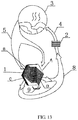
- Fig. 12 and Fig. 13 illustrate a structure of the air condenser proposed in the present embodiment, and an air circulation path inside the heat-pump type clothes dryer.
- the structure of the air condenser in the present embodiment is basically the same as structures of the air condensers in embodiment I and II. Differences are as follows: mounting holes are formed in the cooling sheets 11 in the present embodiment, and heat exchange tubes 10 used for introducing condensed gas or condensed liquid are mounted in the mounting holes.
- a drum 3 on the heat-pump type clothes dryer in the present embodiment is communicated with the first air inlets A and the second air inlets B of the air condenser 1, and the heater 2 is communicated with the first air outlets C and the second air outlets D of the air condenser 1.
- Saturated hot air 5 discharged out of the drum 3 enters the air condenser 1 from the first air inlets A and the second air inlets B, performs heat exchange with the condensed gas or condensed liquid introduced into the heat exchange tubes 10 to become unsaturated hot air 8, and the unsaturated hot air 8 is discharged out of the air condenser 1 from the first air outlets C and the second air outlets D. Meanwhile, condensate water 9 produced in the heat exchange process drips through the heat exchange tubes 10 and is discharged out of the air condenser 1.
- the unsaturated hot air 8 after passing through the air condenser enters the heater 2, is heated to become hot dry air 4 and then enters the drum 3 to continue to dry the clothes.
- the above air condenser is arranged on the clothes dryer in the present invention. Since the above air condenser can effectively recycle waste heat of air in the condensing air ducts, heat exchange efficiency of the heater used for heating the air is increased by 14%-20%, energy consumption is effectively saved, and the heat exchange efficiency is increased. Therefore, the clothes dryer is low in energy consumption and more environmental-friendly in a using process, and market competitiveness of the clothes dryer is improved.
Landscapes
- Engineering & Computer Science (AREA)
- Physics & Mathematics (AREA)
- Thermal Sciences (AREA)
- Mechanical Engineering (AREA)
- General Engineering & Computer Science (AREA)
- Textile Engineering (AREA)
- Detail Structures Of Washing Machines And Dryers (AREA)
- Drying Of Solid Materials (AREA)
Claims (5)
- Condenseur d'air (1) pour un sèche-linge, le sèche-linge comprenant un tambour (3) et un dispositif de chauffage (2), le condenseur d'air (1) comprenant des conduites d'air de condensation (j) et un tuyau de refroidissement (i) agencés transversalement, dans lequel les conduites d'air de condensation (j) comprennent un premier groupe de conduites d'air de condensation (j) et un deuxième groupe de conduites d'air de condensation (j) ; les conduites d'entrée d'air du premier groupe de conduites d'air de condensation (j) et les conduites de sortie d'air du deuxième groupe de conduites d'air de condensation (j) sont au moins partiellement agencées de manière à pouvoir échanger la chaleur ; et les conduites de sortie d'air du premier groupe de conduites d'air de condensation (j) et les conduites d'entrée d'air du deuxième groupe de conduites d'air de condensation (j) sont au moins partiellement agencées de manière à pouvoir échanger la chaleur ;
caractérisé en ce que :les conduites d'air de condensation (j) comprennent des conduites d'air intermédiaires ;au moins une partie des conduites d'air intermédiaires sont placées entre les conduites d'entrée d'air et les conduites de sortie d'air du premier groupe de conduites d'air de condensation (j) et reliées à celles-ci ;au moins une autre partie des conduites d'air intermédiaires sont placées entre les conduites d'entrée d'air et les conduites de sortie d'air du deuxième groupe de conduites d'air de condensation (j) et reliées à celles-ci ; etles conduites d'air intermédiaires et le tuyau de refroidissement (i) sont agencés transversalement pour effectuer un échange de chaleur ;dans lequel un air sec ou un liquide à basse température (6) avant le passage du condenseur d'air (1) entre dans le condenseur d'air (1) à partir d'une entrée du tuyau de refroidissement (i) et effectue un échange de chaleur avec l'air chaud saturé (5) provenant de l'intérieur du tambour (3) et entrant dans les conduites d'air de condensation (j) avant de passer à travers le condenseur d'air (1), dans lequel l'air chaud saturé (5) provient du tambour (3) et entre dans le condenseur d'air (1) à partir des premiers orifices d'entrée d'air (A) du premier groupe de conduites d'air de condensation (j) et des deuxièmes orifices d'entrée d'air (B) du deuxième groupe de conduites d'air de condensation (j) pour effectuer un échange de chaleur pour devenir de l'air chaud non saturé (8), et l'air chaud non saturé (8) est déchargé du condenseur d'air (1) à partir des premières sorties d'air (C) du premier groupe de conduites d'air de condensation (j) et des deuxièmes sorties d'air (D) du deuxième groupe de conduites d'air de condensation (j) pour être collecté pour entrer dans le dispositif de chauffage (2) pour être chauffé ; dans lequel le condenseur d'air (1) comprend deux types d'échange de chaleur, l'un d'eux étant effectué entre l'air dans les premier et deuxième groupes de conduites d'air de condensation (j) et l'air sec ou le liquide (6) dans le tuyau de refroidissement (i), l'autre étant effectué entre l'air dans le premier groupe de conduites d'air de condensation (j) et l'air dans le deuxième groupe de conduites d'air de condensation (j). - Condenseur d'air (1) selon la revendication 1, dans lequel le premier groupe de conduites d'air de condensation (j) comprend au moins une première feuille de condensation (12) ; et ladite au moins une première feuille de condensation (12) est formée avec au moins les conduites d'entrée d'air et les conduites de sortie d'air du premier groupe de conduites d'air de condensation (j) ;
le deuxième groupe de conduites d'air de condensation (j) comprend au moins une deuxième feuille de condensation (13) ; et ladite au moins une deuxième feuille de condensation (13) est formée avec au moins les conduites d'entrée d'air et les conduites de sortie d'air du deuxième groupe de conduites d'air de condensation (j) ;
la première feuille de condensation (12) et la deuxième feuille de condensation (13) sont agencées à des intervalles, de sorte que les conduites d'entrée d'air du premier groupe de conduites d'air de condensation (j) et les conduites de sortie d'air du deuxième groupe de conduites d'air de condensation (j) soient agencées de manière adjacente, et que les protubérances des conduites d'entrée d'air du premier groupe de conduites d'air de condensation (j) et des conduites de sortie d'air du deuxième groupe de conduites d'air de condensation (j) soient au moins partiellement superposées ; et
que les conduites de sortie d'air du premier groupe de conduites d'air de condensation (j) et les conduites d'entrée d'air du deuxième groupe de conduites d'air de condensation (j) soient agencées de manière adjacente, et que les protubérances des conduites de sortie d'air du premier groupe de conduites d'air de condensation (j) et des conduites d'entrée d'air du deuxième groupe de conduites d'air de condensation (j) soient au moins partiellement superposées. - Condenseur d'air (1) selon la revendication 1, dans lequel les conduites d'air intermédiaires sont formées d'un seul tenant ou formées séparément avec les conduites d'entrée d'air et les conduites de sortie d'air du premier groupe de conduites d'air de condensation (j) et du deuxième groupe de conduites d'air de condensation (j).
- Condenseur d'air (1) selon la revendication 1, dans lequel l'air sec ou le liquide à basse température (6) est de l'air à température ambiante.
- Sèche-linge, comprenant un tambour (3) et un dispositif de chauffage (2), et un condenseur d'air (1) selon l'une quelconque des revendications 1 à 4 est agencé dans le sèche-linge ;
dans lequel le tambour (3) est en communication avec les premiers orifices d'entrée d'air (A) et les deuxièmes orifices d'entrée d'air (B) du condenseur d'air (1), dans lequel les premiers orifices d'entrée d'air (A) sont en communication avec les conduites d'entrée d'air du premier groupe de conduites d'air de condensation (j), et les deuxièmes orifices d'entrée d'air (B) sont en communication avec les conduites d'entrée d'air du deuxième groupe de conduites d'air de condensation (j).
Applications Claiming Priority (2)
| Application Number | Priority Date | Filing Date | Title |
|---|---|---|---|
| CN201510057233.XA CN105986454A (zh) | 2015-02-04 | 2015-02-04 | 一种空气冷凝器及干衣机 |
| PCT/CN2015/084070 WO2016123906A1 (fr) | 2015-02-04 | 2015-07-15 | Condenseur à air et machine à sécher le linge |
Publications (3)
| Publication Number | Publication Date |
|---|---|
| EP3255201A1 EP3255201A1 (fr) | 2017-12-13 |
| EP3255201A4 EP3255201A4 (fr) | 2018-12-19 |
| EP3255201B1 true EP3255201B1 (fr) | 2020-09-09 |
Family
ID=56563378
Family Applications (1)
| Application Number | Title | Priority Date | Filing Date |
|---|---|---|---|
| EP15880861.8A Active EP3255201B1 (fr) | 2015-02-04 | 2015-07-15 | Condenseur à air et machine à sécher le linge |
Country Status (6)
| Country | Link |
|---|---|
| US (1) | US20180066893A1 (fr) |
| EP (1) | EP3255201B1 (fr) |
| JP (1) | JP2018504235A (fr) |
| KR (1) | KR20170110120A (fr) |
| CN (1) | CN105986454A (fr) |
| WO (1) | WO2016123906A1 (fr) |
Families Citing this family (6)
| Publication number | Priority date | Publication date | Assignee | Title |
|---|---|---|---|---|
| US10766097B2 (en) * | 2017-04-13 | 2020-09-08 | Raytheon Company | Integration of ultrasonic additive manufactured thermal structures in brazements |
| US10184204B1 (en) * | 2017-06-30 | 2019-01-22 | Wayde L. Wood | Adjustable vent register dryer |
| IL255877B (en) * | 2017-11-23 | 2019-12-31 | Dulberg Sharon | A device for extracting water from the air, and for drying the air using high energy and methods for its production |
| CN112626816A (zh) * | 2019-10-08 | 2021-04-09 | 青岛海尔滚筒洗衣机有限公司 | 一种干衣机冷凝器及干衣机 |
| EP4238474B1 (fr) | 2021-04-22 | 2025-06-25 | Samsung Electronics Co., Ltd. | Appareil de gestion de chaussure et son procédé de commande |
| EP4553217A1 (fr) * | 2023-11-09 | 2025-05-14 | Electrolux Professional AB | Sèche-linge |
Family Cites Families (15)
| Publication number | Priority date | Publication date | Assignee | Title |
|---|---|---|---|---|
| JPH04250199A (ja) * | 1991-01-25 | 1992-09-07 | Nippon Kentetsu Co Ltd | 衣類乾燥機の運転方法 |
| JP4544575B2 (ja) * | 2003-06-11 | 2010-09-15 | 臼井国際産業株式会社 | Egrガス冷却装置 |
| JP4945956B2 (ja) * | 2005-08-23 | 2012-06-06 | パナソニック株式会社 | 除湿装置 |
| NL1032801C2 (nl) * | 2006-11-02 | 2008-05-06 | Johannes Dirk Mooij | Systeem voor het koppelen van twee naast elkaar geplaatste warmtewisselaars en daarbij toe te passen koppeleenheid. |
| EP1936022A1 (fr) * | 2006-12-22 | 2008-06-25 | Electrolux Home Products Corporation N.V. | Sèche-linge |
| KR100826023B1 (ko) * | 2006-12-28 | 2008-04-28 | 엘지전자 주식회사 | 환기 장치의 열교환기 |
| KR100783599B1 (ko) * | 2007-03-09 | 2007-12-07 | 충남대학교산학협력단 | 환기장치용 열교환기 |
| CN201538898U (zh) * | 2009-12-03 | 2010-08-04 | 博西威家用电器有限公司 | 衣物处理桶和使用该衣物处理桶的衣物处理设备 |
| JP5351809B2 (ja) * | 2010-03-25 | 2013-11-27 | 日立アプライアンス株式会社 | 洗濯乾燥機 |
| CN102517857B (zh) * | 2011-11-08 | 2016-08-31 | 青岛海尔滚筒洗衣机有限公司 | 一种具有余热回收功能的干衣冷凝用热交换系统及干衣机 |
| CN102505437B (zh) * | 2011-11-08 | 2016-11-23 | 青岛海尔滚筒洗衣机有限公司 | 一种干衣冷凝用热交换器及干衣机 |
| CN102517861B (zh) * | 2011-12-19 | 2017-09-26 | 青岛海尔滚筒洗衣机有限公司 | 干衣温度检测控制方法及干衣机 |
| EP2735641A1 (fr) * | 2012-11-26 | 2014-05-28 | Electrolux Home Products Corporation N.V. | Procédé pour commander un sèche-linge comprenant un moteur à tambour de ventilateur ou un moteur de ventilateur à vitesse variable |
| US9140396B2 (en) * | 2013-03-15 | 2015-09-22 | Water-Gen Ltd. | Dehumidification apparatus |
| US9677216B2 (en) * | 2013-05-28 | 2017-06-13 | BSH Hausgeräte GmbH | Laundry dryer having a heat exchanger |
-
2015
- 2015-02-04 CN CN201510057233.XA patent/CN105986454A/zh active Pending
- 2015-07-15 EP EP15880861.8A patent/EP3255201B1/fr active Active
- 2015-07-15 WO PCT/CN2015/084070 patent/WO2016123906A1/fr not_active Ceased
- 2015-07-15 US US15/547,733 patent/US20180066893A1/en not_active Abandoned
- 2015-07-15 KR KR1020177024354A patent/KR20170110120A/ko not_active Ceased
- 2015-07-15 JP JP2017541240A patent/JP2018504235A/ja active Pending
Non-Patent Citations (1)
| Title |
|---|
| None * |
Also Published As
| Publication number | Publication date |
|---|---|
| KR20170110120A (ko) | 2017-10-10 |
| WO2016123906A1 (fr) | 2016-08-11 |
| JP2018504235A (ja) | 2018-02-15 |
| EP3255201A4 (fr) | 2018-12-19 |
| US20180066893A1 (en) | 2018-03-08 |
| CN105986454A (zh) | 2016-10-05 |
| EP3255201A1 (fr) | 2017-12-13 |
Similar Documents
| Publication | Publication Date | Title |
|---|---|---|
| EP3255201B1 (fr) | Condenseur à air et machine à sécher le linge | |
| EP2702199B1 (fr) | Seche linge a pompe thermique | |
| CN102517861B (zh) | 干衣温度检测控制方法及干衣机 | |
| US8590172B2 (en) | Dehumidifying apparatus for dryer | |
| EP2778281B1 (fr) | Échangeur de chaleur pour condensation dans le séchage de vêtements et système de séchage de vêtements et dispositif de séchage de vêtements | |
| CN114775215B (zh) | 一种衣物处理装置 | |
| US10604886B2 (en) | Condensation-based clothes dryer and condensation-based clothes drying method | |
| CN117265845B (zh) | 一种衣物处理设备及衣物处理设备的烘干控制方法 | |
| CN113529377B (zh) | 一种衣物烘干设备及其控制方法 | |
| CN201433319Y (zh) | 衣物烘干设备 | |
| CN102505439B (zh) | 一种干衣方法及干衣机 | |
| CN201648804U (zh) | 一种空气冷凝式干衣机用的换热器 | |
| CN108754954B (zh) | 一种分区域过热蒸汽纺织布料烘干定型机及其组合 | |
| CN212983382U (zh) | 一种衣物烘干设备 | |
| WO2013000955A2 (fr) | Sèche-linge équipé d'une pompe à chaleur thermo-électrique | |
| KR20020028340A (ko) | 건조 세탁기 | |
| CN106521908A (zh) | 干衣机 | |
| CN201433318Y (zh) | 衣物烘干设备 | |
| KR101142776B1 (ko) | 히트펌프형 의류건조기 | |
| KR20130010177A (ko) | 의류건조기 | |
| CN201598493U (zh) | 一种干衣机用的冷凝换热器 | |
| CN210215942U (zh) | 具有干衣功能洗衣机用的整体式换热器 | |
| FI102625B (fi) | Menetelmä ja laite lämmön talteenottamiseksi paperikoneen tai vastaava n tyhjöjärjestelmän poistoilmasta | |
| CN110006243B (zh) | 一种蒸发器及果蔬干燥系统 | |
| CN213896430U (zh) | 水气分离的出风模块及衣物烘干装置 |
Legal Events
| Date | Code | Title | Description |
|---|---|---|---|
| STAA | Information on the status of an ep patent application or granted ep patent |
Free format text: STATUS: THE INTERNATIONAL PUBLICATION HAS BEEN MADE |
|
| PUAI | Public reference made under article 153(3) epc to a published international application that has entered the european phase |
Free format text: ORIGINAL CODE: 0009012 |
|
| STAA | Information on the status of an ep patent application or granted ep patent |
Free format text: STATUS: REQUEST FOR EXAMINATION WAS MADE |
|
| 17P | Request for examination filed |
Effective date: 20170901 |
|
| AK | Designated contracting states |
Kind code of ref document: A1 Designated state(s): AL AT BE BG CH CY CZ DE DK EE ES FI FR GB GR HR HU IE IS IT LI LT LU LV MC MK MT NL NO PL PT RO RS SE SI SK SM TR |
|
| AX | Request for extension of the european patent |
Extension state: BA ME |
|
| DAV | Request for validation of the european patent (deleted) | ||
| DAX | Request for extension of the european patent (deleted) | ||
| A4 | Supplementary search report drawn up and despatched |
Effective date: 20181115 |
|
| RIC1 | Information provided on ipc code assigned before grant |
Ipc: F28D 7/08 20060101ALI20181109BHEP Ipc: D06F 58/24 20060101ALI20181109BHEP Ipc: F28D 21/00 20060101ALI20181109BHEP Ipc: F28F 9/02 20060101ALI20181109BHEP Ipc: F28D 9/00 20060101ALI20181109BHEP Ipc: D06F 58/20 20060101AFI20181109BHEP |
|
| STAA | Information on the status of an ep patent application or granted ep patent |
Free format text: STATUS: EXAMINATION IS IN PROGRESS |
|
| RAP1 | Party data changed (applicant data changed or rights of an application transferred) |
Owner name: QINGDAO HAIER WASHING MACHINE CO., LTD. |
|
| 17Q | First examination report despatched |
Effective date: 20191113 |
|
| GRAP | Despatch of communication of intention to grant a patent |
Free format text: ORIGINAL CODE: EPIDOSNIGR1 |
|
| STAA | Information on the status of an ep patent application or granted ep patent |
Free format text: STATUS: GRANT OF PATENT IS INTENDED |
|
| INTG | Intention to grant announced |
Effective date: 20200319 |
|
| GRAS | Grant fee paid |
Free format text: ORIGINAL CODE: EPIDOSNIGR3 |
|
| GRAA | (expected) grant |
Free format text: ORIGINAL CODE: 0009210 |
|
| STAA | Information on the status of an ep patent application or granted ep patent |
Free format text: STATUS: THE PATENT HAS BEEN GRANTED |
|
| AK | Designated contracting states |
Kind code of ref document: B1 Designated state(s): AL AT BE BG CH CY CZ DE DK EE ES FI FR GB GR HR HU IE IS IT LI LT LU LV MC MK MT NL NO PL PT RO RS SE SI SK SM TR |
|
| REG | Reference to a national code |
Ref country code: GB Ref legal event code: FG4D |
|
| REG | Reference to a national code |
Ref country code: AT Ref legal event code: REF Ref document number: 1311704 Country of ref document: AT Kind code of ref document: T Effective date: 20200915 Ref country code: CH Ref legal event code: EP |
|
| REG | Reference to a national code |
Ref country code: DE Ref legal event code: R096 Ref document number: 602015058991 Country of ref document: DE |
|
| REG | Reference to a national code |
Ref country code: IE Ref legal event code: FG4D |
|
| REG | Reference to a national code |
Ref country code: LT Ref legal event code: MG4D |
|
| PG25 | Lapsed in a contracting state [announced via postgrant information from national office to epo] |
Ref country code: FI Free format text: LAPSE BECAUSE OF FAILURE TO SUBMIT A TRANSLATION OF THE DESCRIPTION OR TO PAY THE FEE WITHIN THE PRESCRIBED TIME-LIMIT Effective date: 20200909 Ref country code: GR Free format text: LAPSE BECAUSE OF FAILURE TO SUBMIT A TRANSLATION OF THE DESCRIPTION OR TO PAY THE FEE WITHIN THE PRESCRIBED TIME-LIMIT Effective date: 20201210 Ref country code: NO Free format text: LAPSE BECAUSE OF FAILURE TO SUBMIT A TRANSLATION OF THE DESCRIPTION OR TO PAY THE FEE WITHIN THE PRESCRIBED TIME-LIMIT Effective date: 20201209 Ref country code: SE Free format text: LAPSE BECAUSE OF FAILURE TO SUBMIT A TRANSLATION OF THE DESCRIPTION OR TO PAY THE FEE WITHIN THE PRESCRIBED TIME-LIMIT Effective date: 20200909 Ref country code: BG Free format text: LAPSE BECAUSE OF FAILURE TO SUBMIT A TRANSLATION OF THE DESCRIPTION OR TO PAY THE FEE WITHIN THE PRESCRIBED TIME-LIMIT Effective date: 20201209 Ref country code: HR Free format text: LAPSE BECAUSE OF FAILURE TO SUBMIT A TRANSLATION OF THE DESCRIPTION OR TO PAY THE FEE WITHIN THE PRESCRIBED TIME-LIMIT Effective date: 20200909 Ref country code: LT Free format text: LAPSE BECAUSE OF FAILURE TO SUBMIT A TRANSLATION OF THE DESCRIPTION OR TO PAY THE FEE WITHIN THE PRESCRIBED TIME-LIMIT Effective date: 20200909 |
|
| REG | Reference to a national code |
Ref country code: AT Ref legal event code: MK05 Ref document number: 1311704 Country of ref document: AT Kind code of ref document: T Effective date: 20200909 |
|
| REG | Reference to a national code |
Ref country code: NL Ref legal event code: MP Effective date: 20200909 |
|
| PG25 | Lapsed in a contracting state [announced via postgrant information from national office to epo] |
Ref country code: PL Free format text: LAPSE BECAUSE OF FAILURE TO SUBMIT A TRANSLATION OF THE DESCRIPTION OR TO PAY THE FEE WITHIN THE PRESCRIBED TIME-LIMIT Effective date: 20200909 Ref country code: LV Free format text: LAPSE BECAUSE OF FAILURE TO SUBMIT A TRANSLATION OF THE DESCRIPTION OR TO PAY THE FEE WITHIN THE PRESCRIBED TIME-LIMIT Effective date: 20200909 Ref country code: RS Free format text: LAPSE BECAUSE OF FAILURE TO SUBMIT A TRANSLATION OF THE DESCRIPTION OR TO PAY THE FEE WITHIN THE PRESCRIBED TIME-LIMIT Effective date: 20200909 |
|
| PG25 | Lapsed in a contracting state [announced via postgrant information from national office to epo] |
Ref country code: EE Free format text: LAPSE BECAUSE OF FAILURE TO SUBMIT A TRANSLATION OF THE DESCRIPTION OR TO PAY THE FEE WITHIN THE PRESCRIBED TIME-LIMIT Effective date: 20200909 Ref country code: RO Free format text: LAPSE BECAUSE OF FAILURE TO SUBMIT A TRANSLATION OF THE DESCRIPTION OR TO PAY THE FEE WITHIN THE PRESCRIBED TIME-LIMIT Effective date: 20200909 Ref country code: SM Free format text: LAPSE BECAUSE OF FAILURE TO SUBMIT A TRANSLATION OF THE DESCRIPTION OR TO PAY THE FEE WITHIN THE PRESCRIBED TIME-LIMIT Effective date: 20200909 Ref country code: PT Free format text: LAPSE BECAUSE OF FAILURE TO SUBMIT A TRANSLATION OF THE DESCRIPTION OR TO PAY THE FEE WITHIN THE PRESCRIBED TIME-LIMIT Effective date: 20210111 Ref country code: CZ Free format text: LAPSE BECAUSE OF FAILURE TO SUBMIT A TRANSLATION OF THE DESCRIPTION OR TO PAY THE FEE WITHIN THE PRESCRIBED TIME-LIMIT Effective date: 20200909 |
|
| PG25 | Lapsed in a contracting state [announced via postgrant information from national office to epo] |
Ref country code: ES Free format text: LAPSE BECAUSE OF FAILURE TO SUBMIT A TRANSLATION OF THE DESCRIPTION OR TO PAY THE FEE WITHIN THE PRESCRIBED TIME-LIMIT Effective date: 20200909 Ref country code: AL Free format text: LAPSE BECAUSE OF FAILURE TO SUBMIT A TRANSLATION OF THE DESCRIPTION OR TO PAY THE FEE WITHIN THE PRESCRIBED TIME-LIMIT Effective date: 20200909 Ref country code: AT Free format text: LAPSE BECAUSE OF FAILURE TO SUBMIT A TRANSLATION OF THE DESCRIPTION OR TO PAY THE FEE WITHIN THE PRESCRIBED TIME-LIMIT Effective date: 20200909 Ref country code: IS Free format text: LAPSE BECAUSE OF FAILURE TO SUBMIT A TRANSLATION OF THE DESCRIPTION OR TO PAY THE FEE WITHIN THE PRESCRIBED TIME-LIMIT Effective date: 20210109 |
|
| REG | Reference to a national code |
Ref country code: DE Ref legal event code: R097 Ref document number: 602015058991 Country of ref document: DE |
|
| PG25 | Lapsed in a contracting state [announced via postgrant information from national office to epo] |
Ref country code: SK Free format text: LAPSE BECAUSE OF FAILURE TO SUBMIT A TRANSLATION OF THE DESCRIPTION OR TO PAY THE FEE WITHIN THE PRESCRIBED TIME-LIMIT Effective date: 20200909 |
|
| PLBE | No opposition filed within time limit |
Free format text: ORIGINAL CODE: 0009261 |
|
| STAA | Information on the status of an ep patent application or granted ep patent |
Free format text: STATUS: NO OPPOSITION FILED WITHIN TIME LIMIT |
|
| 26N | No opposition filed |
Effective date: 20210610 |
|
| PG25 | Lapsed in a contracting state [announced via postgrant information from national office to epo] |
Ref country code: DK Free format text: LAPSE BECAUSE OF FAILURE TO SUBMIT A TRANSLATION OF THE DESCRIPTION OR TO PAY THE FEE WITHIN THE PRESCRIBED TIME-LIMIT Effective date: 20200909 Ref country code: SI Free format text: LAPSE BECAUSE OF FAILURE TO SUBMIT A TRANSLATION OF THE DESCRIPTION OR TO PAY THE FEE WITHIN THE PRESCRIBED TIME-LIMIT Effective date: 20200909 |
|
| REG | Reference to a national code |
Ref country code: CH Ref legal event code: PL |
|
| PG25 | Lapsed in a contracting state [announced via postgrant information from national office to epo] |
Ref country code: MC Free format text: LAPSE BECAUSE OF FAILURE TO SUBMIT A TRANSLATION OF THE DESCRIPTION OR TO PAY THE FEE WITHIN THE PRESCRIBED TIME-LIMIT Effective date: 20200909 |
|
| REG | Reference to a national code |
Ref country code: BE Ref legal event code: MM Effective date: 20210731 |
|
| PG25 | Lapsed in a contracting state [announced via postgrant information from national office to epo] |
Ref country code: LI Free format text: LAPSE BECAUSE OF NON-PAYMENT OF DUE FEES Effective date: 20210731 Ref country code: CH Free format text: LAPSE BECAUSE OF NON-PAYMENT OF DUE FEES Effective date: 20210731 |
|
| PG25 | Lapsed in a contracting state [announced via postgrant information from national office to epo] |
Ref country code: LU Free format text: LAPSE BECAUSE OF NON-PAYMENT OF DUE FEES Effective date: 20210715 |
|
| PG25 | Lapsed in a contracting state [announced via postgrant information from national office to epo] |
Ref country code: IE Free format text: LAPSE BECAUSE OF NON-PAYMENT OF DUE FEES Effective date: 20210715 Ref country code: BE Free format text: LAPSE BECAUSE OF NON-PAYMENT OF DUE FEES Effective date: 20210731 |
|
| PG25 | Lapsed in a contracting state [announced via postgrant information from national office to epo] |
Ref country code: HU Free format text: LAPSE BECAUSE OF FAILURE TO SUBMIT A TRANSLATION OF THE DESCRIPTION OR TO PAY THE FEE WITHIN THE PRESCRIBED TIME-LIMIT; INVALID AB INITIO Effective date: 20150715 |
|
| PG25 | Lapsed in a contracting state [announced via postgrant information from national office to epo] |
Ref country code: NL Free format text: LAPSE BECAUSE OF NON-PAYMENT OF DUE FEES Effective date: 20200923 Ref country code: CY Free format text: LAPSE BECAUSE OF FAILURE TO SUBMIT A TRANSLATION OF THE DESCRIPTION OR TO PAY THE FEE WITHIN THE PRESCRIBED TIME-LIMIT Effective date: 20200909 |
|
| PG25 | Lapsed in a contracting state [announced via postgrant information from national office to epo] |
Ref country code: MK Free format text: LAPSE BECAUSE OF FAILURE TO SUBMIT A TRANSLATION OF THE DESCRIPTION OR TO PAY THE FEE WITHIN THE PRESCRIBED TIME-LIMIT Effective date: 20200909 |
|
| PG25 | Lapsed in a contracting state [announced via postgrant information from national office to epo] |
Ref country code: MT Free format text: LAPSE BECAUSE OF FAILURE TO SUBMIT A TRANSLATION OF THE DESCRIPTION OR TO PAY THE FEE WITHIN THE PRESCRIBED TIME-LIMIT Effective date: 20200909 |
|
| PGFP | Annual fee paid to national office [announced via postgrant information from national office to epo] |
Ref country code: DE Payment date: 20250722 Year of fee payment: 11 |
|
| PGFP | Annual fee paid to national office [announced via postgrant information from national office to epo] |
Ref country code: IT Payment date: 20250724 Year of fee payment: 11 |
|
| PGFP | Annual fee paid to national office [announced via postgrant information from national office to epo] |
Ref country code: GB Payment date: 20250722 Year of fee payment: 11 |
|
| PGFP | Annual fee paid to national office [announced via postgrant information from national office to epo] |
Ref country code: FR Payment date: 20250725 Year of fee payment: 11 |
|
| PG25 | Lapsed in a contracting state [announced via postgrant information from national office to epo] |
Ref country code: TR Free format text: LAPSE BECAUSE OF FAILURE TO SUBMIT A TRANSLATION OF THE DESCRIPTION OR TO PAY THE FEE WITHIN THE PRESCRIBED TIME-LIMIT Effective date: 20200909 |