EP3258504A1 - Solarbatterie, verfahren zur herstellung einer solarbatterie, verfahren zur herstellung eines solarzellenmoduls und solarzellenmodul - Google Patents
Solarbatterie, verfahren zur herstellung einer solarbatterie, verfahren zur herstellung eines solarzellenmoduls und solarzellenmodul Download PDFInfo
- Publication number
- EP3258504A1 EP3258504A1 EP17185369.0A EP17185369A EP3258504A1 EP 3258504 A1 EP3258504 A1 EP 3258504A1 EP 17185369 A EP17185369 A EP 17185369A EP 3258504 A1 EP3258504 A1 EP 3258504A1
- Authority
- EP
- European Patent Office
- Prior art keywords
- adhesive agent
- solar
- solar cell
- wires
- solar battery
- Prior art date
- Legal status (The legal status is an assumption and is not a legal conclusion. Google has not performed a legal analysis and makes no representation as to the accuracy of the status listed.)
- Pending
Links
Images


Classifications
-
- H—ELECTRICITY
- H10—SEMICONDUCTOR DEVICES; ELECTRIC SOLID-STATE DEVICES NOT OTHERWISE PROVIDED FOR
- H10F—INORGANIC SEMICONDUCTOR DEVICES SENSITIVE TO INFRARED RADIATION, LIGHT, ELECTROMAGNETIC RADIATION OF SHORTER WAVELENGTH OR CORPUSCULAR RADIATION
- H10F19/00—Integrated devices, or assemblies of multiple devices, comprising at least one photovoltaic cell covered by group H10F10/00, e.g. photovoltaic modules
- H10F19/90—Structures for connecting between photovoltaic cells, e.g. interconnections or insulating spacers
- H10F19/902—Structures for connecting between photovoltaic cells, e.g. interconnections or insulating spacers for series or parallel connection of photovoltaic cells
- H10F19/908—Structures for connecting between photovoltaic cells, e.g. interconnections or insulating spacers for series or parallel connection of photovoltaic cells for back-contact photovoltaic cells
-
- H—ELECTRICITY
- H10—SEMICONDUCTOR DEVICES; ELECTRIC SOLID-STATE DEVICES NOT OTHERWISE PROVIDED FOR
- H10F—INORGANIC SEMICONDUCTOR DEVICES SENSITIVE TO INFRARED RADIATION, LIGHT, ELECTROMAGNETIC RADIATION OF SHORTER WAVELENGTH OR CORPUSCULAR RADIATION
- H10F19/00—Integrated devices, or assemblies of multiple devices, comprising at least one photovoltaic cell covered by group H10F10/00, e.g. photovoltaic modules
- H10F19/80—Encapsulations or containers for integrated devices, or assemblies of multiple devices, having photovoltaic cells
- H10F19/85—Protective back sheets
-
- H—ELECTRICITY
- H10—SEMICONDUCTOR DEVICES; ELECTRIC SOLID-STATE DEVICES NOT OTHERWISE PROVIDED FOR
- H10F—INORGANIC SEMICONDUCTOR DEVICES SENSITIVE TO INFRARED RADIATION, LIGHT, ELECTROMAGNETIC RADIATION OF SHORTER WAVELENGTH OR CORPUSCULAR RADIATION
- H10F77/00—Constructional details of devices covered by this subclass
- H10F77/93—Interconnections
- H10F77/933—Interconnections for devices having potential barriers
- H10F77/935—Interconnections for devices having potential barriers for photovoltaic devices or modules
- H10F77/937—Busbar structures for modules
-
- Y—GENERAL TAGGING OF NEW TECHNOLOGICAL DEVELOPMENTS; GENERAL TAGGING OF CROSS-SECTIONAL TECHNOLOGIES SPANNING OVER SEVERAL SECTIONS OF THE IPC; TECHNICAL SUBJECTS COVERED BY FORMER USPC CROSS-REFERENCE ART COLLECTIONS [XRACs] AND DIGESTS
- Y02—TECHNOLOGIES OR APPLICATIONS FOR MITIGATION OR ADAPTATION AGAINST CLIMATE CHANGE
- Y02E—REDUCTION OF GREENHOUSE GAS [GHG] EMISSIONS, RELATED TO ENERGY GENERATION, TRANSMISSION OR DISTRIBUTION
- Y02E10/00—Energy generation through renewable energy sources
- Y02E10/50—Photovoltaic [PV] energy
-
- Y—GENERAL TAGGING OF NEW TECHNOLOGICAL DEVELOPMENTS; GENERAL TAGGING OF CROSS-SECTIONAL TECHNOLOGIES SPANNING OVER SEVERAL SECTIONS OF THE IPC; TECHNICAL SUBJECTS COVERED BY FORMER USPC CROSS-REFERENCE ART COLLECTIONS [XRACs] AND DIGESTS
- Y10—TECHNICAL SUBJECTS COVERED BY FORMER USPC
- Y10T—TECHNICAL SUBJECTS COVERED BY FORMER US CLASSIFICATION
- Y10T156/00—Adhesive bonding and miscellaneous chemical manufacture
- Y10T156/10—Methods of surface bonding and/or assembly therefor
Definitions
- the present invention relates to a solar battery, a method for manufacturing a solar battery, a method for manufacturing a solar cell module, and a solar cell module, in particular, a solar battery in which electrodes of a solar cell and wires of a wiring substrate can be electrically connected to each other at a low temperature readily to attain highly reliable connection therebetween and relatively good electric characteristics; a method for manufacturing the solar battery; a method for manufacturing a solar cell module using the solar battery; and the solar cell module.
- An exemplary mainstream solar battery of such solar batteries is conventionally a dual-side electrode type solar battery.
- a monocrystalline or polycrystalline silicon substrate has a light-receiving surface in which an impurity of conductive type opposite to that of the silicon substrate is diffused to form a pn junction. Electrodes are formed on the light-receiving surface and rear surface opposite thereto in the silicon substrate.
- a so-called back-side electrode type solar battery is being developed in which both p type electrodes and n type electrodes are formed in the rear surface of a silicon substrate.
- silicon substrates are getting thinner.
- solar cells are getting thinner, which disadvantageously results in cracks in cells caused upon operations for wiring the solar cells during fabrication of solar cell modules.
- Patent document 1 proposes a method for wiring solar cells using a wiring substrate configured to include a base material, and wires formed on the base material.
- solder In the case where electrodes of a solar cell and wires of a wiring substrate are connected to each other via a solder, when a general lead-free solder (Sn-Ag-Cu-based solder or the like) is used, the solder needs to be heated to around 250°C. Where the solder needs to be heated to such a high temperature to connect the electrodes of the solar cell and the wires of the wiring substrate to each other, stress is generated due to a difference in thermal expansion coefficient between the silicon substrate of the solar cell and the wire material of the wiring substrate during cooling after the high temperature heating, which results in a crack in the solar cell or decreased reliability in the connection therebetween such as removal of the solar cell from the wiring substrate.
- a general lead-free solder Sn-Ag-Cu-based solder or the like
- Patent document 2 Japanese Patent Laying-Open No. 2005-175436
- ACF Anaisotropic Conductive Film
- the ACF is expensive, which makes it difficult to use the ACF for a solar cell having a large surface area.
- the ACF have too large electric resistance for a large current to flow therein, resulting in decreased electric characteristics of the solar battery such as F.F (Fill Factor).
- an object of the present invention is to provide a solar battery in which electrodes of a solar cell and wires of a wiring substrate can be electrically connected to each other at a low temperature readily to attain highly reliable connection therebetween and relatively good electric characteristics; a method for manufacturing the solar battery; a method for manufacturing a solar cell module using the solar battery; and the solar cell module.
- the present invention provides a solar battery including a solar cell; a wiring substrate having a wire to be electrically connected to an electrode provided in the solar cell; and an adhesive agent for adhering the solar cell and the wiring substrate to each other.
- the wiring substrate includes an insulative base material and the wire formed on the insulative base material, the wire is formed of a conductive material, and the adhesive agent is disposed on the insulative base material in at least a part of a region other than a region in which the wire is formed.
- the insulative base material preferably includes at least one of polyethylene terephthalate and polyethylene naphthalate.
- the insulative base material may also serve as a weather-resistant film.
- the wire is preferably formed of a material including at least one selected from a group consisting of copper, aluminum, and silver.
- the adhesive agent preferably includes at least one selected from a group consisting of a silicone-based adhesive agent, an acrylic-based adhesive agent, an epoxy-based adhesive agent, and a rubber-based adhesive agent.
- the adhesive agent preferably has stable adhesiveness even when exposed to an environment at a temperature of 150°C or greater.
- the adhesive agent is preferably a viscous adhesive agent.
- the solar cell is preferably a back-side electrode type solar cell.
- the electrode of the solar cell preferably has a shape of at least one of a strip and a dot.
- the electrode of the solar cell and the wire of the wiring substrate may be electrically connected to each other via a conductive adhesive agent.
- the conductive adhesive agent preferably has a melting temperature/hardening temperature of 180°C or smaller.
- the conductive adhesive agent preferably has an electric resistivity of 0.001 ⁇ cm or smaller.
- the conductive adhesive agent is preferably an Sn-Bi-based solder.
- the present invention provides a method for manufacturing the solar battery, including the steps of: disposing a viscous adhesive layer on a base material; disposing the wire on the viscous adhesive layer; disposing the wire, disposed on the viscous adhesive layer, on the adhesive agent disposed on the insulative base material; and removing the wire from the viscous adhesive layer to transfer the wire onto the adhesive agent.
- the present invention provides a method for manufacturing the solar battery, including the steps of: applying the adhesive agent to at least one of the solar cell and the wiring substrate; and adhering the solar cell and the wiring substrate using the adhesive agent.
- the adhesive agent is applied using any of screen-printing, offset printing, inkjet printing, and a dispenser.
- the present invention provides a method for manufacturing a solar cell module in which the solar battery is sealed in a sealing material, wherein when sealing the solar battery, the electrode of the solar cell and the wire of the wiring substrate are mechanically compressed and bonded.
- the present invention provides a method for manufacturing a solar cell module in which the solar battery is sealed in a sealing material, wherein when sealing the solar battery, the electrode of the solar cell and the wire of the wiring substrate are mechanically compressed and bonded with the conductive adhesive agent interposed therebetween.
- the present invention provides a solar cell module in which the solar battery is sealed in a sealing material, wherein the sealing material is contained in a container having, on at least one of its bottom portion and its side wall, a moisture penetration preventing layer for preventing penetration of moisture.
- an inexpensive solar battery in which electrodes of a solar cell and wires of a wiring substrate are electrically connected to each other at a low temperature readily to attain highly reliable connection therebetween and relatively good electric characteristics; a method for manufacturing a solar cell module using the solar battery; and the solar cell module.
- 100 solar cell; 101: silicon substrate; 102: anti-reflection film; 103: passivation film; 104: n type impurity doping region; 105: p type impurity doping region; 106: n electrode; 107: p electrode; 108: conductive adhesive agent; 109: wire for n type; 110: wire for p type; 111: insulative substrate; 112: slit; 113: connection electrode; 114: busbar p electrode; 115: busbar n electrode; 116: conductive member; 120: adhesive agent; 121: base material; 122: hardening resin; 124: transparent substrate; 125: sealing material; 126: insulative film; 127: metal film; 128: container; 200: wiring substrate.
- Fig. 1 shows a schematic cross sectional view of one exemplary solar battery of the present invention.
- the solar battery shown in Fig. 1 has solar cells 100 and a wiring substrate 200.
- Each of solar cells 100 has an n type or p type silicon substrate 101.
- Silicon substrate 101 has a light-receiving surface (surface of a side via which sunlight mainly enter) on which an anti-reflection film 102 is formed and has a rear surface (surface opposite to the light-receiving surface) in which n type impurity doping regions 104 formed by diffusing an n type impurity and p type impurity doping regions 105 formed by diffusing a p type impurity are provided alternately with a predetermined space therebetween.
- a passivation film 103 Provided on the rear surface of silicon substrate 101 is a passivation film 103. N electrodes 106 penetrating through contact holes formed in passivation film 103 are formed to make contact with n type impurity doping regions 104, and p electrode 107 penetrating therethrough are formed to make contact with p type impurity doping regions 105.
- Wiring substrate 200 has an insulative substrate 111 as well as wires for n type 109 and wires for p type 110 both formed on insulative substrate 111.
- n electrodes 106 of solar cell 100 are electrically connected to wires for n type 109 of wiring substrate 200, whereas p electrodes 107 are electrically connected to wires for p type 110 of wiring substrate 200.
- a feature of the solar battery of the present invention lies in that the connection between n electrodes 106 of solar cell 100 and wires for n type 109 of wiring substrate 200 and the connection between p electrodes 107 and the wires for p type 110 of wiring substrate 200 are achieved through adhesion provided by an adhesive agent 120 between solar cell 100 and wiring substrate 200.
- solar cell 100 and wiring substrate 200 are fixed to each other by means of the adhesion provided by adhesive agent 120 between solar cell 100 and wiring substrate 200 as such, solar cell 100 can be fixed onto wiring substrate 200 only by aligning and disposing solar cell 100 on wiring substrate 200. Thereafter, for example, the solar battery thus obtained is sealed in a sealing material such as a resin to fabricate a solar cell module. In this way, good electric connection through mechanical compression bonding is achieved. By fabricating the solar cell module in this way, they are less likely to be displaced from each other after the solar cell is placed on the wiring substrate using the adhesive agent. As such, the step of connecting using a solder, which requires heating at approximately 250°C, can be omitted, thus readily realizing highly reliable connection at a low temperature.
- a solder which requires heating at approximately 250°C
- n electrodes 106 of solar cell 100 and wires for n type 109 of wiring substrate 200 are in direct contact with each other and p electrodes 107 of solar cell 100 and wires for p type 110 of wiring substrate 200 are also in direct contact with each other, electric resistance at the connection portions can be reduced as compared with the case where they are connected using an ACF, thereby achieving relatively good electric characteristics of the solar battery such as F.F.
- Fig. 2 shows a schematic cross sectional view of another exemplary solar battery of the present invention.
- the solar battery shown in Fig. 2 is different from the solar battery shown in Fig. 1 in that the connection between n electrodes 106 of solar cell 100 and wires for n type 109 of wiring substrate 200 and the connection between p electrodes 107 of solar cell 100 and wires for p type 110 of wiring substrate 200 are achieved using a conductive adhesive agent 108.
- solar cell 100 and wiring substrate 200 are fixed to each other by adhesive agent 120 provided therebetween.
- adhesive agent 120 provided therebetween.
- conductive adhesive agent 108 may be provided and thereafter they may be heated in a reflow furnace and accordingly connected to each other.
- conductive adhesive agent 108 for example, an Sn-Bi-based solder, which has a low melting point, is inexpensive, and has a low electric resistance.
- the Sn-Bi-based solder is adhered in advance to at least one of each electrode of solar cell 100 and each wire of wiring substrate 200, and solar cell 100 is placed on wiring substrate 200.
- Solar cell 100 and wiring substrate 200 are fixed to each other by adhesive agent 120. Thereafter, they are not heated in a reflow furnace or the like, and are sealed in a sealing material as with the description above.
- the step of heating using a reflow furnace can be omitted because heat generated during the process of sealing and mechanical compression bonding provided by the sealing securely achieve electric connection with conductive adhesive agent 108 interposed therebetween. This holds true for a case where a conductive adhesive agent of low-temperature hardening type (including a conductive adhesive agent other than a solder) different from the Sn-Bi-based solder is used as conductive adhesive agent 108.
- connection locations of solar cell 100 and wiring substrate 200 can be prevented from being displaced from each other during a period of time until the solar battery is sealed in the sealing material to complete the fabrication of the solar cell module. In this way, highly reliable connection is achieved. Further, it can be expected to reinforce the connection between solar cell 100 and wiring substrate 200 after the solar battery is sealed.
- adhesive agent 120 any material can be used without a particular limitation as long as it is capable of adhering solar cell 100 and wiring substrate 200 to each other.
- a material usable therefor is a material containing at least one selected from a group consisting of a silicone-based adhesive agent, an acrylic-based adhesive agent, an epoxy-based adhesive agent, and a rubber-based adhesive agent, each of which has a high heat resistance.
- the silicone-based adhesive agent, the acrylic-based adhesive agent, the epoxy-based adhesive agent, and the rubber-based adhesive agent that can be used herein are, for example, conventionally known ones.
- a viscous adhesive agent is used as adhesive agent 120.
- stress can be absorbed due to flexibility of the viscous adhesive material to avoid poor connection between solar cell 100 and wiring substrate 200.
- cracks in solar cell 100 are likely to be effectively prevented.
- solar cell 100 and wiring substrate 200 can be detached from each other and then can be connected again to each other, advantageously.
- a viscous adhesive agent is one type of adhesive agent, which has viscosity in general, has fluidity against an adhered material under application of pressure, and has retention power provided by aggregation against removal instead of hardening.
- the solar battery needs to be heated.
- adhesive agent 120 it is preferable to use an adhesive agent exhibiting stable adhesiveness even when exposed to an environment at a temperature of 150°C or greater, and it is more preferable to use one exhibiting stable adhesiveness even when exposed to an environment at a temperature of 180°C or greater.
- the “stable adhesiveness” described above indicates such adhesiveness that provides viscosity even under application of heat and does not cause displacement of the solar cell and the wiring substrate even when an impact such as vibration is applied. Further, the adhesive agent preferably has stable adhesiveness after the heating, and preferably secures the electric connection therebetween by adhering the solar cell and the wiring substrate to each other.
- exemplary adhesive agents exhibiting stable adhesiveness when exposed to an environment at a temperature of 180°C or greater are SD4570, which is a silicone-based adhesive agent, provided by the Dow Corning Corporation; 9079, which is an acrylic-based adhesive agent, provided by the Sumitomo 3M Limited.; C-1080A/B, which is an epoxy-based adhesive agent, provided by the Nacalai Tesuque, Inc; and the like.
- Another exemplary adhesive agent is DB5441, which is a screen-printable acrylic-based adhesive agent (viscous adhesive agent), provided by the Diabond Industry co., Ltd, or the like, and can be patterned and formed on the base material of wiring substrate 200 and/or portions of solar cell 100 other than the electrodes.
- a viscous tape can be used which has a PET base material or PEN base material to which an adhesive agent (viscous adhesive agent) is applied in advance.
- examples thereof are PET tape YT153S, which employs a PET base material and a silicone-based adhesive agent, provided by the YOUNGWOO CO., LTD.; a tape No.754, which employs a PET base material and an acrylic-based adhesive agent, provided by the Sumitomo 3M Limited; a tape No.4734, which employs a PET base material and a rubber-based adhesive agent, provided by the Sumitomo 3M Limited; and T4900, G9052, etc., which are acrylic-based viscous adhesive agents (double-sided tape), provided by the Sony Chemicals Corporation. These exhibit stable adhesiveness even when exposed to an environment at a temperature of 150°C or greater.
- adhesive agent 120 is preferably provided in at least a portion of wiring substrate 200 other than the wires.
- insulative substrate 111 used for wiring substrate 200 for example, a substrate made of a material having an electric resistance higher than those of wires for n type 109 and wires for p type 110 can be used.
- PEN polyethylene naphthalate
- PET polyethylene terephthalate
- wires for n type 109 and wires for p type 110 used in wiring substrate 200 any material can be used without a particular limitation as long as it is made of a conductive material. However, for further reduction in electric resistance of the wires, they are preferably formed of a material including at least one selected from a group consisting of copper, aluminum, and silver. It should be noted that wires for n type 109 and wires for p type 110 may be formed of the same material or different materials.
- conductive adhesive agent 108 for example, agents made of a conductive material can be used. Among them, it is preferable to use one having its melting temperature or hardening temperature of 180°C or smaller, more preferably, of 150°C or smaller. For simplification of steps, conductive adhesive agent 108 is preferably melted or hardened in the step of sealing the solar battery because the step of sealing is normally performed at a temperature of 180°C or smaller. Furthermore, when conductive adhesive agent 108 has a melting temperature or hardening temperature of 180°C or smaller and for example a PEN film is used for insulative substrate 111 of wiring substrate 200, insulative substrate 111 is hardly shrunk by heat. Likewise, when conductive adhesive agent 108 has a melting temperature or hardening temperature of 150°C or smaller and for example a PET film is used for insulative substrate 111 of wiring substrate 200, insulative substrate 111 is hardly shrunk by heat.
- the melting temperature of conductive adhesive agent 108 refers to a temperature at which conductive adhesive agent 108 starts to be melted
- the hardening temperature of conductive adhesive agent 108 refers to a temperature at which conductive adhesive agent 108 starts to be hardened
- Sn-Bi-based solder As conductive adhesive agent 108, it is preferable to use an Sn-Bi-based solder.
- Sn-Bi-based solder used for conductive adhesive agent 108 is melted at a low temperature of, for example, approximately 140-150°C, is therefore processed at a low temperature, is available at an inexpensive price, is easy in handling, and provides a low electric resistance to conductive adhesive agent 108.
- the Sn-Bi-based solder refers to a solder containing Sn and Bi as main components among metals constituting the solder, the total mass of Sn and Bi being 90% by mass or greater of the entire mass of the solder.
- conductive adhesive agent 108 preferably has an electric resistivity of 0.001 ⁇ cm or smaller.
- the solar cell it is preferable to use, for example, a back-side electrode type solar cell configured to have both n electrodes and p electrodes formed only on the rear surface of a semiconductor substrate such as a silicon substrate as shown in Fig. 1 or Fig. 2 .
- a back-side electrode type solar cell configured to have both n electrodes and p electrodes formed only on the rear surface of a semiconductor substrate such as a silicon substrate as shown in Fig. 1 or Fig. 2 .
- members constituting the solar cell for example, conventionally known members can be used.
- Fig. 3 (a) shows a schematic planar view of one exemplary rear surface of the solar cell used in the present invention.
- n electrodes 106 and p electrodes 107 are formed to have shapes of strips extending in the same direction in the rear surface of silicon substrate 101 (the left-right direction of the plane of Fig. 3(a) ).
- Such strip-shaped n electrodes 106 and p electrodes 107 are arranged alternately one by one in the top-bottom direction of the plane of Fig. 3 (a) .
- Fig. 3(b) shows a schematic planar view of another exemplary rear surface of the solar cell used in the present invention.
- n electrodes 106 and p electrodes 107 are formed to have shapes of dots.
- dot-shaped n electrodes 106 are arranged adjacent to one another and dot-shaped p electrodes 107 are arranged adjacent to one another.
- Dot-shaped n electrodes 106 and dot-shaped p electrodes 107 shown in Fig. 3(b) are arranged in straight lines in the top-bottom direction and left-right direction in the plane of Fig. 3(b) .
- Each of n electrodes 106 and p electrodes 107 on the rear surface of the solar cell preferably has a shape such as the strip as illustrated in Fig. 3(a) and/or a shape such as the dot as illustrated in Fig. 3(b) . In these cases, voids are less likely to be left between the solar cell and the wiring substrate upon sealing the solar battery in a sealing material as described below.
- Fig. 4 shows a schematic planar view of one exemplary wiring substrate used in the present invention.
- insulative substrate 111 of wiring substrate 200 has a surface provided with wires for n type 109 and wires for p type 110 as well as connection electrodes 113 for electrically connecting wires for n type 109 and wires for p type 110 to each other.
- busbar p electrode 114 for collecting charges is electrically connected to wires for p type 110 provided at one end of insulative substrate 111 in the longitudinal direction
- busbar n electrode 115 for collecting charges is electrically connected to wires for n type 109 provided at the other end thereof
- the adhesive agent (not shown) is provided in at least a part of regions on the surface of insulative substrate 111 other than wires for n type 109, wires for p type 110, connection electrodes 113, busbar p electrode 114, and busbar n electrode 115.
- busbar p electrode 114 and busbar n electrode 115 On both busbar p electrode 114 and busbar n electrode 115, slits 112 are provided to serve as openings for positioning.
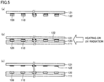
- a method for manufacturing the wiring substrate used in the present invention will be described below.
- hardening resins 122 are applied on a surface of an appropriate base material 121.
- hardening resins 122 for example, conductive sheets such as copper foils are adhered.
- Each of the conductive sheets is etched to have a predetermined shape, thus forming wires for n type 109 and wires for p type 110.
- An exemplary hardening resin used as each of hardening resins 122 is a conventionally known hardening resin of a type which loses viscosity by heating and/or UV (ultraviolet radiation).
- base material 121 thus provided with wires for n type 109 and wires for p type 110 fabricated as above is attached and adhered to insulative substrate 111 on which adhesive agent 120 is provided. Interfaces between hardening resins 122 on base material 121 and each of wires for n type 109 and wires for p type 110 are heated and/or subjected to UV radiation. Accordingly, hardening resins 122 lose their viscosity, and wires for n type 109 and wires for p type 110 are removed from hardening resins 122.
- the wiring substrate can be formed which has a configuration in which adhesive agent 120 is exposed in at least a portion of a region on the surface of insulative substrate 111 other than wires for n type 109 and wires for p type 110.
- hardening resins 122 may be heated and/or subjected to UV radiation before base material 121 and insulative substrate 111 are attached and adhered to each other.
- base material 121 from which wires for n type 109 and wires for p type 110 have been transferred to adhesive agent 120 is reusable as a member for the solar cell module fabricated by sealing the solar battery in the sealing material.
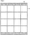
- Fig. 6 shows a schematic planar view of one exemplary solar battery of the present invention, which is fabricated by, for example, installing solar cells on wiring substrates on which the adhesive agent is provided.
- slits 112 may be used for alignment of the installation locations of solar cells 100 on wiring substrates 200.
- busbar p electrode 114 of one wiring substrate 200 and busbar n electrode 115 of the other wiring substrate 200 are electrically connected to each other by conductive members 116.
- conductive members 116 there may be adopted such a configuration that does not employ conductive members 116 but allows solar cells 100 to be electrically connected in series naturally when placing solar cells 100 on a wiring substrate 200, such as the wire pattern of wiring substrate 200 in an embodiment shown in Fig. 7 .
- insulative substrate 111 which serves as a base material for wiring substrate 200, may be used to also serve as a weather-resistant film.
- a screen-printable adhesive agent 120 is pattern-printed on portions of the rear surface of solar cell 100 other than the electrodes.
- adhesive agent 120 may be printed on the wiring substrate 200 side, it is preferable to print it on the solar cell 100 side due to the following reasons: the electrodes of solar cell 100 can be thinner than the wires of wiring substrate 200 and the portions other than the electrodes therefore have large areas, which makes it easier to print thereon; and it is easier to perform an operation of baking adhesive agent 120 as solar cell 100 is smaller in size.
- solar cell 100 and wiring substrate 200 are placed on each other so that the electrodes of solar cell 100 match with the wires of wiring substrate 200, and are adhered to each other.
- adhesive agent 120 is applied using a dispenser or the like onto the surface of insulative substrate 111 on which wires for n type 109 and wires for p type 110 are patterned and/or the rear surface of solar cell 100, and then solar cell 100 is placed on wiring substrate 200.
- Fig. 9 shows a schematic cross sectional view of one exemplary solar cell module of the present invention, which is fabricated by, for example, sealing the solar battery in a sealing material.
- the solar battery having solar cells 100 placed on wiring substrate 200 is sealed in sealing material 125 contained in a container 128 constituted by a layered film formed by interposing a metal film 127 between opposing two insulative films 126.
- Sealing material 125 has a surface provided with a transparent substrate 124.
- transparent substrate 124 for example, a substrate transparent to sunlight can be used such as a conventionally known glass substrate.
- sealing material 125 for example, a resin or the like transparent to sunlight can be used such as a conventionally known EVA (ethylene vinyl acetate) resin.
- each of insulative films 126 for example, a conventionally known one can be used such as a PET film. Further, when container 128 is used as insulative substrate 111 serving as the base material of wiring substrate 200, the insulative substrate of wiring substrate 200 can be used as a weather-resistant film without modification. Further, as metal film 127, for example, a conventionally known one can be used such as a metal film of aluminum or the like.
- solar cell 100 is placed on wiring substrate 200.
- the electric connection between the electrodes of solar cell 100 and the wires of wiring substrate 200 can be secured more, thus achieving further improved reliability in the connection.
- the solar battery can be sealed in sealing material 125 using, for example, a method including a step of compressing and bonding sealing material 125 and a step of hardening sealing material 125 as follows.
- a method including a step of compressing and bonding sealing material 125 and a step of hardening sealing material 125 as follows.
- the above-described solar battery is inserted between sealing material 125 formed on transparent substrate 124 and sealing material 125 contained in container 128, and is subjected to vacuum compression bonding and the like while being heated, thereby compressing and bonding sealing material 125 provided on transparent substrate 124 and sealing material 125 contained in container 128 (step of compressing and bonding).
- the solar battery is contained in sealing material 125 filling a space surrounded by transparent substrate 124 and container 128.
- sealing material 125 is hardened by further heating or the like (step of hardening), thus sealing the solar battery configured as above in sealing material 125 between transparent substrate 124 and container 128.
- the hardening of sealing material 125 allows the electrodes of solar cell 100 and the wires of wiring substrate 200 to be compressed and bonded to each other mechanically, thus achieving more secured electric connection between the electrodes of solar cell 100 and the wires of wiring substrate 200. In this way, reliability of the connection is further improved.
- fabricating the solar cell module as described above does not require a step of applying a conductive adhesive agent and heating it in a reflow furnace. Hence, the number of steps can be reduced, whereby the solar cell module can be fabricated more easily.
- a conductive adhesive agent having a melting temperature or hardening temperature of 180°C or smaller is more preferable to use a conductive adhesive agent having a melting temperature or hardening temperature of 150°C or smaller, and is particularly preferable to use an Sn-Bi-based solder having a melting temperature of 150°C or smaller.
- the solar cell module can be fabricated by sealing the solar battery in sealing material 125 in the same way apart from the use of conductive adhesive agent 108.
- solder is preferably applied onto the wires of wiring substrate 200 and/or the electrodes of solar cell 100 through solder plating or soaking in a melted solder bath in advance and the electrodes of solar cell 100 and the wires of wiring substrate 200 are then brought into electric connection.
- the electrodes of solar cell 100 and the wires of wiring substrate 200 can be electrically connected to each other with the conductive adhesive agent interposed therebetween during the step of compressing and bonding and/or the step of hardening, by for example heat generated in the step of compressing and bonding sealing material 125 and/or the step of hardening.
- the solder has been applied in advance onto the wires of wiring substrate 200 and/or the electrodes of solar cell 100, thereby preventing production of a gas such as one generated when heating a cream solder.
- a gas such as one generated when heating a cream solder.
- this method is preferable because the electric connection between the electrodes of solar cell 100 and the wires of wiring substrate 200 can be more secured by conductive adhesive agent 108.
- the solar battery in the case where the solar battery fabricated by electrically connecting the electrodes of solar cell 100 and the wires of wiring substrate 200 to each other is sealed in the sealing material to fabricate the solar cell module, the solar battery can be protected from application of heat, apart from heat generated while fixing them by adhesive agent 120 at a normal temperature as well as heat in the step of compressing and bonding sealing material 125 and/or in the step of hardening.
- This can reduce stress conventionally generated due to a difference in thermal expansion coefficient between a solar cell and a wire material of a wiring substrate. Accordingly, the solar cell can be prevented from being cracked, thus obtaining a thinner solar cell. Furthermore, influence of thermal stress during an actual operation of the solar cell module can be reduced too.
- a container 128 including a moisture penetration preventing layer such as metal film 127 formed of aluminum or the like which is greatly effective to prevent penetration of water vapor, as shown in the embodiment of Fig. 9 .
- Entrance of water vapor into the solar cell module is likely to cause corrosion at interfaces between the electrodes of solar cell 100 and the wires of wiring substrate 200, or corrosion of conductive adhesive agent 108 provided between the electrodes of solar cell 100 and the wires of wiring substrate 200 (particularly, corrosion of the Sn-Bi-based solder).
- container 128 including the above-described moisture penetration preventing layer the corrosion can be prevented effectively, thus achieving improved long-term reliability of the solar cell module.
- container 128 including the moisture penetration preventing layer for example, as shown in the embodiment of Fig. 9 , it is preferable to use a layered film in which metal film 127 formed of aluminum is interposed between insulative films 126 each formed of PET.
- a moisture penetration preventing tape such as a butyl rubber tape can be used to achieve complete intimate contact.
- the wiring substrate of the above-described solar cell module and a terminal box may be connected using a conductive member, and the solar cell module may be fit in and surrounded by a frame body made of aluminum or the like.
- back-side electrode type solar cells each having a rear surface formed as shown in Fig. 3(a) were fabricated using a conventionally known method.
- Each solar - cell 100 was configured so that strip-shaped n electrodes 106 and p electrodes 107 were arranged alternately one by one on the rear surface of n type silicon substrate 101 having a light-receiving surface and a rear surface both having a shape of square with each side of 100 mm.
- a wiring substrate 200 was fabricated.
- adhesive agent 120 an acrylic-based viscous adhesive agent was used.
- a solar battery was fabricated in which solar cells 100 were fixed onto wiring substrate 200 by adhesive agent 120.
- n electrodes 106 of each of sixteen solar cells 100 were placed on wires for n type 109 of wiring substrate 200 and p electrodes 107 of each solar cell 100 were placed on wires for p type 110 of wiring substrate 200, while using slits 112 of wiring substrate 200 as alignment marks for alignment thereof
- the solar battery fabricated as described above was sealed in a sealing material to fabricate a solar cell module as shown in Fig. 9 .
- the solar battery was interposed between a sealing material 125 made of an EVA resin and formed on a transparent substrate 124 constituted by a glass substrate and a sealing material 125 made of an EVA resin and contained in a container 128 constituted by a layered film in which a metal film 127 made of aluminum was interposed between insulative films 126 made of PET, was thereafter subjected to vacuum thermo-compression bonding to compress and bond sealing material 125 provided on transparent substrate 124 and sealing material 125 contained in container 128 (step of compressing and bonding), and thereafter sealing materials 125 were hardened by heating (step of hardening).
- the step of compressing and bonding was performed by placing, on sealing material 125 contained in container 128, sealing material 125 formed on transparent substrate 124, and retaining them for seven minutes at 140°C while evacuating it.
- the step of hardening was performed after the step of compressing and bonding, by heating sealing materials 125 at 145°C for 40 minutes to harden sealing materials 125 each made of an EVA resin. In this way, the electrodes of each solar cell 100 and the wires of wiring substrate 200 are in further intimate contact with each other.
- the solar cell module fabricated as described above was connected to a terminal box, and was fit in and surrounded by a frame body made of aluminum.
- a solar cell module having a solar battery, which is sealed therein and in which electrodes of a solar cell and wires of a wiring substrate are electrically connected to each other at a low temperature readily to attain highly reliable connection therebetween and relatively good electric characteristics.
- insulative substrate 111 an inexpensive PET can be used as insulative substrate 111. Furthermore, it can be fabricated without application of a conductive adhesive agent and heating with a reflow furnace, thus achieving reduction of the number of steps.
- back-side electrode type solar cells each having a rear surface formed as shown in Fig. 3(a) were fabricated using a conventionally known method.
- Each solar cell 100 was configured so that strip-shaped n electrodes 106 and p electrodes 107 were arranged alternately one by one on the rear surface of n type silicon substrate 101 having a light-receiving surface and a rear surface both having a shape of square with each side of 100 mm
- Each of the solar cells was soaked in an Sn-Bi solder bath to coat the electrode portions with the solder.
- an acrylic-based viscous adhesive agent was applied to a portion of the rear surface of the solar cell other than the electrodes provided thereon, by means of screen printing. Thereafter, it was baked at 100°C, thus exhibiting viscosity of the viscous adhesive agent.
- a solar battery was fabricated in which solar cells 100 were fixed onto wiring substrate 200 by adhesive agent 120.
- n electrodes 106 of each of sixteen solar cells 100 were placed on wires for n type 109 of wiring substrate 200 and p electrodes 107 of each solar cell 100 were placed on wires for p type 110 of wiring substrate 200, while using slits 112 of wiring substrate 200 as alignment marks for alignment thereof.
- the solder provided in advance to coat the electrodes of the solar cell was melted to connect the electrodes of the solar cell and the wires of the wiring substrates to each other, thus achieving more reliable connection therebetween.
- the solar cell module fabricated as described above was connected to a terminal box, and was fit in and surrounded by a frame body made of aluminum.
- a solar battery in which electrodes of a solar cell and wires of a wiring substrate can be electrically connected to each other at a low temperature readily to attain highly reliable connection therebetween and relatively good electric characteristics; a method for manufacturing the solar battery; a method for manufacturing a solar cell module using the solar battery; and the solar cell module.
Landscapes
- Photovoltaic Devices (AREA)
Applications Claiming Priority (2)
| Application Number | Priority Date | Filing Date | Title |
|---|---|---|---|
| JP2007254403A JP5252472B2 (ja) | 2007-09-28 | 2007-09-28 | 太陽電池、太陽電池の製造方法、太陽電池モジュールの製造方法および太陽電池モジュール |
| EP08833628.4A EP2211389B1 (de) | 2007-09-28 | 2008-08-29 | Solarbatterie, verfahren zur herstellung einer solarbatterie, verfahren zur herstellung eines solarbatteriemoduls und solarbatteriemodul |
Related Parent Applications (1)
| Application Number | Title | Priority Date | Filing Date |
|---|---|---|---|
| EP08833628.4A Division EP2211389B1 (de) | 2007-09-28 | 2008-08-29 | Solarbatterie, verfahren zur herstellung einer solarbatterie, verfahren zur herstellung eines solarbatteriemoduls und solarbatteriemodul |
Publications (1)
| Publication Number | Publication Date |
|---|---|
| EP3258504A1 true EP3258504A1 (de) | 2017-12-20 |
Family
ID=40511105
Family Applications (2)
| Application Number | Title | Priority Date | Filing Date |
|---|---|---|---|
| EP17185369.0A Pending EP3258504A1 (de) | 2007-09-28 | 2008-08-29 | Solarbatterie, verfahren zur herstellung einer solarbatterie, verfahren zur herstellung eines solarzellenmoduls und solarzellenmodul |
| EP08833628.4A Active EP2211389B1 (de) | 2007-09-28 | 2008-08-29 | Solarbatterie, verfahren zur herstellung einer solarbatterie, verfahren zur herstellung eines solarbatteriemoduls und solarbatteriemodul |
Family Applications After (1)
| Application Number | Title | Priority Date | Filing Date |
|---|---|---|---|
| EP08833628.4A Active EP2211389B1 (de) | 2007-09-28 | 2008-08-29 | Solarbatterie, verfahren zur herstellung einer solarbatterie, verfahren zur herstellung eines solarbatteriemoduls und solarbatteriemodul |
Country Status (5)
| Country | Link |
|---|---|
| US (2) | US9349896B2 (de) |
| EP (2) | EP3258504A1 (de) |
| JP (1) | JP5252472B2 (de) |
| CN (2) | CN102867874B (de) |
| WO (1) | WO2009041212A1 (de) |
Families Citing this family (140)
| Publication number | Priority date | Publication date | Assignee | Title |
|---|---|---|---|---|
| US8238944B2 (en) * | 2002-04-16 | 2012-08-07 | Hewlett-Packard Development Company, L.P. | Disaster and emergency mode for mobile radio phones |
| US9848447B2 (en) * | 2007-06-27 | 2017-12-19 | Ford Global Technologies, Llc | Method and system for emergency notification |
| JP5252472B2 (ja) * | 2007-09-28 | 2013-07-31 | シャープ株式会社 | 太陽電池、太陽電池の製造方法、太陽電池モジュールの製造方法および太陽電池モジュール |
| US20100051085A1 (en) * | 2008-08-27 | 2010-03-04 | Weidman Timothy W | Back contact solar cell modules |
| WO2010116973A1 (ja) * | 2009-04-08 | 2010-10-14 | シャープ株式会社 | 配線シート、配線シート付き太陽電池セル、太陽電池モジュールおよび配線シート付き太陽電池セルの製造方法 |
| KR20120010251A (ko) * | 2009-04-23 | 2012-02-02 | 샤프 가부시키가이샤 | 배선 시트, 배선 시트가 부착된 태양 전지 셀, 및 태양 전지 모듈 |
| JP2010258158A (ja) * | 2009-04-23 | 2010-11-11 | Sharp Corp | 配線シート、配線シート付き太陽電池セルおよび太陽電池モジュール |
| JP2010283052A (ja) * | 2009-06-03 | 2010-12-16 | Sharp Corp | 配線シート、裏面電極型太陽電池セル、配線シート付き太陽電池セルおよび太陽電池モジュール |
| JP5273728B2 (ja) * | 2009-06-05 | 2013-08-28 | シャープ株式会社 | 配線シート付き太陽電池セルおよび太陽電池モジュール |
| JP5172783B2 (ja) * | 2009-06-18 | 2013-03-27 | シャープ株式会社 | 配線シート付き太陽電池セルおよび太陽電池モジュール |
| EP2448008A1 (de) | 2009-06-22 | 2012-05-02 | Sharp Kabushiki Kaisha | Solarzelle, solarzellen mit verkabelungsplatte daran und solarzellenmodul |
| JP4988065B2 (ja) * | 2009-06-29 | 2012-08-01 | シャープ株式会社 | 配線シート、配線シート付き太陽電池セル、太陽電池モジュールおよび配線シートロール |
| JP2011054721A (ja) * | 2009-09-01 | 2011-03-17 | Sharp Corp | 被接合部材の接合方法および接合構造体 |
| JP4678698B2 (ja) * | 2009-09-15 | 2011-04-27 | シャープ株式会社 | 太陽電池モジュールおよびその製造方法 |
| JP4875124B2 (ja) * | 2009-09-17 | 2012-02-15 | シャープ株式会社 | 太陽電池モジュール |
| JP5642370B2 (ja) * | 2009-09-29 | 2014-12-17 | 三洋電機株式会社 | 太陽電池モジュール |
| JP5046308B2 (ja) * | 2009-10-09 | 2012-10-10 | シャープ株式会社 | 配線シート、配線シート付き太陽電池セル、太陽電池モジュールおよび配線シートロール |
| US8962986B2 (en) * | 2009-10-15 | 2015-02-24 | Hitachi Chemical Company, Ltd. | Conductive adhesive, solar cell, method for manufacturing solar cell, and solar cell module |
| JP2011091327A (ja) * | 2009-10-26 | 2011-05-06 | Sharp Corp | 太陽電池モジュールおよび太陽電池モジュールの製造方法 |
| JP5459596B2 (ja) * | 2009-10-28 | 2014-04-02 | 凸版印刷株式会社 | 太陽電池用裏面保護シート及び太陽電池モジュール |
| JP2011108969A (ja) * | 2009-11-20 | 2011-06-02 | Hitachi Cable Ltd | 太陽電池モジュールの製造方法、及び太陽電池用配線基板 |
| CN102110727A (zh) * | 2009-11-20 | 2011-06-29 | 日立电线株式会社 | 太阳电池模块,以及太阳电池模块用布线电路板 |
| JP2011114205A (ja) * | 2009-11-27 | 2011-06-09 | Sharp Corp | 太陽電池モジュールの製造方法および太陽電池モジュール |
| JP5556146B2 (ja) * | 2009-11-30 | 2014-07-23 | 三洋電機株式会社 | 太陽電池モジュールの製造方法 |
| JP5378424B2 (ja) * | 2010-01-22 | 2013-12-25 | シャープ株式会社 | 配線シート付き太陽電池セル、太陽電池モジュールおよび配線シート付き太陽電池セルの製造方法 |
| KR20120104431A (ko) | 2010-01-22 | 2012-09-20 | 샤프 가부시키가이샤 | 이면 전극형 태양전지 셀, 배선 시트, 배선 시트를 가진 태양전지 셀, 태양전지 모듈 및 배선 시트를 가진 태양전지 셀의 제조방법 |
| JP5369009B2 (ja) * | 2010-01-22 | 2013-12-18 | シャープ株式会社 | 配線シート付き太陽電池セルおよび太陽電池モジュール |
| JP2011155133A (ja) * | 2010-01-27 | 2011-08-11 | Sharp Corp | 太陽電池装置 |
| JP5299975B2 (ja) * | 2010-02-23 | 2013-09-25 | シャープ株式会社 | 裏面電極型太陽電池セル、配線シート、配線シート付き太陽電池セルおよび太陽電池モジュール |
| JP5569139B2 (ja) * | 2010-05-12 | 2014-08-13 | 凸版印刷株式会社 | 太陽電池モジュール |
| JP5876226B2 (ja) * | 2010-07-09 | 2016-03-02 | 大日本印刷株式会社 | 太陽電池用集電シート及びそれを用いた太陽電池モジュール |
| US8946547B2 (en) * | 2010-08-05 | 2015-02-03 | Solexel, Inc. | Backplane reinforcement and interconnects for solar cells |
| JP5998442B2 (ja) * | 2010-09-01 | 2016-09-28 | 大日本印刷株式会社 | 太陽電池用集電シート及びそれを用いた太陽電池モジュール |
| JP2012060018A (ja) * | 2010-09-10 | 2012-03-22 | Sharp Corp | 太陽電池モジュールの製造方法 |
| JP5834709B2 (ja) * | 2010-09-30 | 2015-12-24 | 大日本印刷株式会社 | 太陽電池集電用シート及びそれを用いた太陽電池モジュール |
| JP5558306B2 (ja) * | 2010-10-06 | 2014-07-23 | シャープ株式会社 | 太陽電池モジュール |
| JP5159860B2 (ja) * | 2010-10-21 | 2013-03-13 | シャープ株式会社 | 配線シート付き太陽電池セル、太陽電池モジュール、配線シート付き太陽電池セルの製造方法および太陽電池モジュールの製造方法 |
| JP5140133B2 (ja) * | 2010-10-29 | 2013-02-06 | シャープ株式会社 | 配線シート付き太陽電池セルの製造方法、太陽電池モジュールの製造方法、配線シート付き太陽電池セルおよび太陽電池モジュール |
| JP5140132B2 (ja) * | 2010-10-29 | 2013-02-06 | シャープ株式会社 | 配線基板付き裏面電極型太陽電池セル、太陽電池モジュールおよび配線基板付き裏面電極型太陽電池セルの製造方法 |
| TWI593322B (zh) | 2010-11-19 | 2017-07-21 | 帝斯曼知識產權資產管理有限公司 | 金屬箔圖案積層體、金屬箔之模切方法、電路基板及其製造方法、以及太陽能電池模組 |
| JP5879754B2 (ja) * | 2011-06-06 | 2016-03-08 | 凸版印刷株式会社 | 回路基板の製造方法 |
| JP4944240B1 (ja) * | 2010-11-30 | 2012-05-30 | シャープ株式会社 | 裏面電極型太陽電池セル、配線シート付き裏面電極型太陽電池セル、太陽電池モジュール、配線シート付き裏面電極型太陽電池セルの製造方法および太陽電池モジュールの製造方法 |
| JP5231515B2 (ja) * | 2010-12-17 | 2013-07-10 | シャープ株式会社 | 太陽電池の製造方法 |
| JP2012164912A (ja) * | 2011-02-09 | 2012-08-30 | Toppan Printing Co Ltd | 太陽電池用配線シート及びその製造方法、並びにそれを用いた太陽電池モジュール |
| JP5591146B2 (ja) * | 2011-02-17 | 2014-09-17 | 三菱電機株式会社 | 配線付き絶縁シートとその製造方法、太陽電池セル一体型配線付き絶縁シートとその製造方法、太陽電池モジュールの製造方法 |
| JP5214755B2 (ja) * | 2011-03-03 | 2013-06-19 | シャープ株式会社 | 裏面電極型太陽電池セル、裏面電極型太陽電池サブセルおよび太陽電池モジュール |
| JPWO2012141073A1 (ja) * | 2011-04-11 | 2014-07-28 | 三菱電機株式会社 | 太陽電池モジュールおよびその製造方法 |
| KR101254564B1 (ko) | 2011-05-18 | 2013-04-19 | 엘지전자 주식회사 | 태양 전지 모듈 |
| EP3300125B1 (de) | 2011-06-06 | 2020-01-15 | DSM IP Assets B.V. | Metallfolienstrukturiertes laminat und solarzellenmodul |
| KR101194864B1 (ko) | 2011-06-07 | 2012-10-26 | 주식회사 에스에너지 | 후면전극형 태양전지 모듈 및 그 제조방법 |
| KR101982885B1 (ko) * | 2011-07-29 | 2019-05-27 | 히타치가세이가부시끼가이샤 | 접착제 조성물, 그것을 이용한 필름상 접착제 및 회로 접속 재료, 회로 부재의 접속 구조 및 그의 제조 방법 |
| JP5886588B2 (ja) * | 2011-10-18 | 2016-03-16 | デクセリアルズ株式会社 | 導電性接着剤、並びに、それを用いた太陽電池モジュール、及びその製造方法 |
| US8889981B2 (en) | 2011-10-18 | 2014-11-18 | Samsung Sdi Co., Ltd. | Photoelectric device |
| US8497153B2 (en) | 2011-10-31 | 2013-07-30 | E I Du Pont De Nemours And Company | Integrated back-sheet for back contact photovoltaic module |
| US20130104959A1 (en) * | 2011-10-31 | 2013-05-02 | E I Du Pont De Nemours And Company | Integrated back-sheet for back contact photovoltaic module |
| WO2013066815A1 (en) * | 2011-10-31 | 2013-05-10 | E. I. Du Pont De Nemours And Company | Solar cell module and process for making the same |
| CN103890968A (zh) * | 2011-10-31 | 2014-06-25 | E.I.内穆尔杜邦公司 | 用于背接触式光伏组件的集成背板 |
| US8328077B1 (en) * | 2011-11-01 | 2012-12-11 | Flextronics Ap, Llc | PV cell mass reflow |
| JP5758787B2 (ja) * | 2011-12-14 | 2015-08-05 | 株式会社日立製作所 | 太陽電池モジュールの製造装置 |
| US9306103B2 (en) * | 2011-12-22 | 2016-04-05 | E I Du Pont De Nemours And Company | Back contact photovoltaic module with integrated circuitry |
| JP2012099853A (ja) * | 2012-02-03 | 2012-05-24 | Sharp Corp | 配線シート付き太陽電池セルの製造方法、太陽電池モジュールの製造方法、配線シート付き太陽電池セルおよび太陽電池モジュール |
| JP2012099854A (ja) * | 2012-02-03 | 2012-05-24 | Sharp Corp | 配線シート付き太陽電池セルの製造方法、太陽電池モジュールの製造方法、配線シート付き太陽電池セルおよび太陽電池モジュール |
| EP2713405B1 (de) | 2012-02-29 | 2018-05-16 | Dai Nippon Printing Co., Ltd. | Kollektorplatte für eine solarzelle und solarzellenmodul damit |
| JP2015516145A (ja) * | 2012-04-02 | 2015-06-08 | ソレクセル、インコーポレイテッド | 高効率太陽電池構造体及びその製造方法 |
| CN102709359B (zh) * | 2012-05-08 | 2014-11-26 | 常州天合光能有限公司 | 太阳能电池组件复合式导电背板及其制备和使用方法 |
| IN2014DN08762A (de) | 2012-05-22 | 2015-05-22 | Dsm Ip Assets Bv | |
| JP2014011232A (ja) * | 2012-06-28 | 2014-01-20 | Hitachi Chemical Co Ltd | 太陽電池素子、太陽電池素子の製造方法、太陽電池モジュールの製造方法及び太陽電池モジュール |
| JP6063669B2 (ja) * | 2012-08-09 | 2017-01-18 | シャープ株式会社 | 電子機器及び電子機器の製造方法 |
| US9515217B2 (en) | 2012-11-05 | 2016-12-06 | Solexel, Inc. | Monolithically isled back contact back junction solar cells |
| JP2016500931A (ja) * | 2012-11-05 | 2016-01-14 | ソレクセル、インコーポレイテッド | 一体アイル型太陽光発電セル及びモジュールのためのシステム及び方法 |
| US9812592B2 (en) | 2012-12-21 | 2017-11-07 | Sunpower Corporation | Metal-foil-assisted fabrication of thin-silicon solar cell |
| CN103972315B (zh) * | 2013-01-25 | 2017-07-04 | 纳幕尔杜邦公司 | 集成式背板、背接触式光生伏打模块及其生产方法 |
| WO2014139099A1 (en) * | 2013-03-13 | 2014-09-18 | China Sunergy (Nanjing) Co., Ltd. | Soldering system |
| US9666739B2 (en) * | 2013-06-28 | 2017-05-30 | Sunpower Corporation | Photovoltaic cell and laminate metallization |
| US10553738B2 (en) * | 2013-08-21 | 2020-02-04 | Sunpower Corporation | Interconnection of solar cells in a solar cell module |
| US9437756B2 (en) | 2013-09-27 | 2016-09-06 | Sunpower Corporation | Metallization of solar cells using metal foils |
| KR102319721B1 (ko) * | 2013-10-29 | 2021-11-01 | 엘지전자 주식회사 | 태양 전지 및 태양 전지 모듈 |
| KR102124520B1 (ko) * | 2013-10-29 | 2020-06-18 | 엘지전자 주식회사 | 태양 전지 모듈 및 그 제조 방법 |
| JP2014042065A (ja) * | 2013-11-01 | 2014-03-06 | Hitachi Metals Ltd | 太陽電池用リード線及び太陽電池 |
| KR102132940B1 (ko) | 2013-11-29 | 2020-07-10 | 엘지전자 주식회사 | 태양 전지 및 그 제조 방법 |
| US9653638B2 (en) | 2013-12-20 | 2017-05-16 | Sunpower Corporation | Contacts for solar cells formed by directing a laser beam with a particular shape on a metal foil over a dielectric region |
| US9178104B2 (en) | 2013-12-20 | 2015-11-03 | Sunpower Corporation | Single-step metal bond and contact formation for solar cells |
| KR102162720B1 (ko) * | 2014-01-14 | 2020-10-07 | 엘지전자 주식회사 | 태양 전지 |
| KR102162718B1 (ko) * | 2014-01-17 | 2020-10-07 | 엘지전자 주식회사 | 태양 전지 모듈 |
| KR102184941B1 (ko) * | 2014-02-24 | 2020-12-01 | 엘지전자 주식회사 | 태양 전지 및 그 제조 방법 |
| KR102175893B1 (ko) | 2014-02-24 | 2020-11-06 | 엘지전자 주식회사 | 태양 전지 모듈의 제조 방법 |
| US9496437B2 (en) * | 2014-03-28 | 2016-11-15 | Sunpower Corporation | Solar cell having a plurality of sub-cells coupled by a metallization structure |
| US9947812B2 (en) | 2014-03-28 | 2018-04-17 | Sunpower Corporation | Metallization of solar cells |
| US9231129B2 (en) | 2014-03-28 | 2016-01-05 | Sunpower Corporation | Foil-based metallization of solar cells |
| NL2012563B1 (en) * | 2014-04-03 | 2016-03-08 | Stichting Energieonderzoek Centrum Nederland | Solar cell module and method manufacturing such a module. |
| US9818903B2 (en) | 2014-04-30 | 2017-11-14 | Sunpower Corporation | Bonds for solar cell metallization |
| KR102257815B1 (ko) * | 2014-08-04 | 2021-05-28 | 엘지전자 주식회사 | 태양 전지 모듈 |
| KR102257820B1 (ko) * | 2014-08-14 | 2021-05-28 | 엘지전자 주식회사 | 태양 전지 모듈 |
| KR102298437B1 (ko) * | 2014-08-27 | 2021-09-07 | 엘지전자 주식회사 | 태양 전지 모듈 |
| KR102303464B1 (ko) * | 2014-08-27 | 2021-09-17 | 엘지전자 주식회사 | 배선 기판 제조 방법 및 태양 전지 모듈의 제조 방법 |
| US9257575B1 (en) | 2014-09-18 | 2016-02-09 | Sunpower Corporation | Foil trim approaches for foil-based metallization of solar cells |
| KR102298434B1 (ko) * | 2014-09-22 | 2021-09-07 | 엘지전자 주식회사 | 태양 전지 모듈과 그 제조 방법 |
| JP6199839B2 (ja) * | 2014-09-30 | 2017-09-20 | 信越化学工業株式会社 | 太陽電池及びその製造方法 |
| US9620661B2 (en) | 2014-12-19 | 2017-04-11 | Sunpower Corporation | Laser beam shaping for foil-based metallization of solar cells |
| US20160284887A1 (en) * | 2015-03-27 | 2016-09-29 | Gabriel Harley | Crack prevention for solar cells |
| CN107667435B (zh) * | 2015-05-21 | 2020-02-28 | 夏普株式会社 | 光电转换装置 |
| US10535790B2 (en) | 2015-06-25 | 2020-01-14 | Sunpower Corporation | One-dimensional metallization for solar cells |
| US20160380127A1 (en) | 2015-06-26 | 2016-12-29 | Richard Hamilton SEWELL | Leave-In Etch Mask for Foil-Based Metallization of Solar Cells |
| US20160380120A1 (en) | 2015-06-26 | 2016-12-29 | Akira Terao | Metallization and stringing for back-contact solar cells |
| US9935213B2 (en) | 2015-06-26 | 2018-04-03 | Sunpower Corporation | Wire-based metallization for solar cells |
| US20170054045A1 (en) * | 2015-08-21 | 2017-02-23 | Institute of Nuclear Energy Research, Atomic Energy Council, Executive Yuan, R.O.C. | Method for packaging solar cell device and structure thereof |
| US10840394B2 (en) | 2015-09-25 | 2020-11-17 | Total Marketing Services | Conductive strip based mask for metallization of semiconductor devices |
| JP6590165B2 (ja) * | 2015-09-30 | 2019-10-16 | パナソニックIpマネジメント株式会社 | 太陽電池セルの製造方法 |
| US9620655B1 (en) | 2015-10-29 | 2017-04-11 | Sunpower Corporation | Laser foil trim approaches for foil-based metallization for solar cells |
| US10516066B2 (en) * | 2016-03-23 | 2019-12-24 | Sharp Kabushiki Kaisha | Photovoltaic conversion device, photovoltaic module, and solar power generation system |
| US11424373B2 (en) | 2016-04-01 | 2022-08-23 | Sunpower Corporation | Thermocompression bonding approaches for foil-based metallization of non-metal surfaces of solar cells |
| US10290763B2 (en) | 2016-05-13 | 2019-05-14 | Sunpower Corporation | Roll-to-roll metallization of solar cells |
| US9882071B2 (en) | 2016-07-01 | 2018-01-30 | Sunpower Corporation | Laser techniques for foil-based metallization of solar cells |
| JP6205031B2 (ja) * | 2016-08-03 | 2017-09-27 | シャープ株式会社 | 電子機器及び電子機器の製造方法 |
| US10115855B2 (en) | 2016-09-30 | 2018-10-30 | Sunpower Corporation | Conductive foil based metallization of solar cells |
| US10084098B2 (en) | 2016-09-30 | 2018-09-25 | Sunpower Corporation | Metallization of conductive wires for solar cells |
| US10580735B2 (en) | 2016-10-07 | 2020-03-03 | Xcelsis Corporation | Stacked IC structure with system level wiring on multiple sides of the IC die |
| CN106847936B (zh) * | 2016-12-07 | 2019-01-01 | 清华大学 | 基于金属键合的光电器件封装结构及其制造方法 |
| US11908958B2 (en) | 2016-12-30 | 2024-02-20 | Maxeon Solar Pte. Ltd. | Metallization structures for solar cells |
| WO2018142544A1 (ja) * | 2017-02-02 | 2018-08-09 | 三菱電機株式会社 | 太陽電池モジュールおよび太陽電池モジュールの製造方法 |
| JP2018014540A (ja) * | 2017-10-25 | 2018-01-25 | 日立化成株式会社 | 太陽電池素子、太陽電池素子の製造方法、太陽電池モジュールの製造方法及び太陽電池モジュール |
| US11362234B2 (en) | 2018-04-06 | 2022-06-14 | Sunpower Corporation | Local patterning and metallization of semiconductor structures using a laser beam |
| KR20200130495A (ko) | 2018-04-06 | 2020-11-18 | 선파워 코포레이션 | 태양 전지 스트링잉을 위한 레이저 보조 금속화 공정 |
| US11276785B2 (en) | 2018-04-06 | 2022-03-15 | Sunpower Corporation | Laser assisted metallization process for solar cell fabrication |
| US11646387B2 (en) | 2018-04-06 | 2023-05-09 | Maxeon Solar Pte. Ltd. | Laser assisted metallization process for solar cell circuit formation |
| CN112136218B (zh) | 2018-04-06 | 2024-07-09 | 迈可晟太阳能有限公司 | 用于太阳能电池电路形成的激光辅助金属化工艺 |
| CN111354808B (zh) * | 2018-12-20 | 2025-11-18 | 东君新能源有限公司 | 一种太阳能芯片及其制备方法 |
| US20220140168A1 (en) * | 2019-03-05 | 2022-05-05 | Longi Solar Technology (Taizhou) Co., Ltd. | Back-contact solar cell conductive composite board and preparation method therefor, back-contact solar cell interconnection structure, and double-sided back-contact solar cell module |
| JP2020161515A (ja) * | 2019-03-25 | 2020-10-01 | セイコーエプソン株式会社 | 光電変換モジュール、電子時計、電子機器および光電変換モジュールの製造方法 |
| CN110112232A (zh) * | 2019-04-30 | 2019-08-09 | 北京铂阳顶荣光伏科技有限公司 | 薄膜太阳能电池前板及其制备方法 |
| CN110481031B (zh) * | 2019-08-09 | 2021-06-18 | 江苏日托光伏科技股份有限公司 | 一种大尺寸组件用窄幅铜铝芯板覆膜拼接装置及方法 |
| WO2021232715A1 (zh) * | 2020-05-21 | 2021-11-25 | 晶澳太阳能有限公司 | 背接触太阳能电池组件及制备方法 |
| KR102198277B1 (ko) * | 2020-09-16 | 2021-01-05 | 엘지전자 주식회사 | 태양 전지 및 태양 전지 모듈 |
| CN113193058A (zh) * | 2021-05-28 | 2021-07-30 | 浙江爱旭太阳能科技有限公司 | 一种背接触太阳能电池串及制备方法、组件及系统 |
| DE202021104400U1 (de) * | 2021-08-17 | 2021-10-27 | Hermann Hogg | PV-Modul mit direktkontaktierenden Leitern |
| TWI798951B (zh) * | 2021-11-22 | 2023-04-11 | 凌巨科技股份有限公司 | 半穿透式太陽能電池 |
| CN114792745B (zh) * | 2022-06-24 | 2023-05-23 | 山东芯源微电子有限公司 | 一种高效的太阳能发电基片导线区掺杂方法 |
| JP7473601B2 (ja) | 2022-07-21 | 2024-04-23 | シャープ株式会社 | 太陽電池モジュール |
| JP7633211B2 (ja) | 2022-07-21 | 2025-02-19 | シャープ株式会社 | 太陽電池モジュール |
| CN120588658B (zh) * | 2025-08-06 | 2025-10-31 | 金阳(泉州)新能源科技有限公司 | 柔性组件锡膏印刷方法及系统 |
Citations (7)
| Publication number | Priority date | Publication date | Assignee | Title |
|---|---|---|---|---|
| US3874931A (en) * | 1969-12-12 | 1975-04-01 | Communications Satellite Corp | Solar cell array |
| JPH08298334A (ja) * | 1995-04-26 | 1996-11-12 | Mitsubishi Electric Corp | 太陽電池板 |
| US20020134422A1 (en) * | 2001-03-20 | 2002-09-26 | The Boeing Company | Solar tile and associated method for fabricating the same |
| JP2005175436A (ja) | 2003-10-06 | 2005-06-30 | Semiconductor Energy Lab Co Ltd | 半導体装置及びその作製方法 |
| JP2005340362A (ja) | 2004-05-25 | 2005-12-08 | Sharp Corp | 太陽電池セルおよび太陽電池モジュール |
| US20060213548A1 (en) * | 2005-03-22 | 2006-09-28 | Applied Materials, Inc. | Scalable photovoltaic cell and solar panel manufacturing with improved wiring |
| EP2109149A1 (de) * | 2007-01-25 | 2009-10-14 | Sharp Kabushiki Kaisha | Solarbatteriezelle, solarbatteriearray, solarbatteriemodul und verfahren zur herstellung eines solarbatteriearrays |
Family Cites Families (30)
| Publication number | Priority date | Publication date | Assignee | Title |
|---|---|---|---|---|
| US3994012A (en) * | 1975-05-07 | 1976-11-23 | The Regents Of The University Of Minnesota | Photovoltaic semi-conductor devices |
| JPS6252185A (ja) * | 1985-08-29 | 1987-03-06 | エヌオーケー株式会社 | 多孔質セラミツクス膜の製造法 |
| JPS6251285A (ja) * | 1985-08-30 | 1987-03-05 | シャープ株式会社 | 回路接続構造 |
| JPH01120335A (ja) | 1987-11-04 | 1989-05-12 | Daicel Huels Ltd | 複合金属板 |
| JPH0530360Y2 (de) * | 1988-02-05 | 1993-08-03 | ||
| JPH02181475A (ja) * | 1989-01-06 | 1990-07-16 | Mitsubishi Electric Corp | 太陽電池セル及びその製造方法 |
| US5694188A (en) | 1994-09-17 | 1997-12-02 | Kabushiki Kaisha Toshiba | Reflection type liquid crystal display device having comb-shaped wall electrode |
| US5972732A (en) * | 1997-12-19 | 1999-10-26 | Sandia Corporation | Method of monolithic module assembly |
| US5951786A (en) * | 1997-12-19 | 1999-09-14 | Sandia Corporation | Laminated photovoltaic modules using back-contact solar cells |
| US6160215A (en) * | 1999-03-26 | 2000-12-12 | Curtin; Lawrence F. | Method of making photovoltaic device |
| JP3792433B2 (ja) * | 1999-04-19 | 2006-07-05 | シャープ株式会社 | 光又は放射線検出素子ならびに二次元画像検出器の製造方法 |
| US6313396B1 (en) * | 2000-05-22 | 2001-11-06 | The Boeing Company | Lightweight solar module and method of fabrication |
| JP2003101049A (ja) * | 2001-09-27 | 2003-04-04 | Sanyo Electric Co Ltd | 光電変換装置の製造方法 |
| US8847063B2 (en) * | 2003-07-07 | 2014-09-30 | Dow Corning Corporation | Encapsulation of solar cells |
| JP4409323B2 (ja) | 2004-03-24 | 2010-02-03 | シャープ株式会社 | 太陽電池セル評価装置及びそれを備えたソーラーシミュレータ |
| US7390961B2 (en) * | 2004-06-04 | 2008-06-24 | Sunpower Corporation | Interconnection of solar cells in a solar cell module |
| FR2877144B1 (fr) | 2004-10-22 | 2006-12-08 | Solarforce Soc Par Actions Sim | Structure multicouche monolithique pour la connexion de cellules a semi-conducteur |
| JP2007019334A (ja) * | 2005-07-08 | 2007-01-25 | Mitsubishi Electric Corp | 太陽電池装置 |
| US20070012352A1 (en) * | 2005-07-18 | 2007-01-18 | Bp Corporation North America Inc. | Photovoltaic Modules Having Improved Back Sheet |
| US20070095384A1 (en) * | 2005-10-28 | 2007-05-03 | Farquhar Donald S | Photovoltaic modules and interconnect methodology for fabricating the same |
| CH696344A5 (fr) * | 2006-02-22 | 2007-04-30 | Ses Soc En Solaire Sa | Film support et procédé de couplage de cellules photovoltaïques. |
| US7498508B2 (en) | 2006-02-24 | 2009-03-03 | Day4 Energy, Inc. | High voltage solar cell and solar cell module |
| JP4663664B2 (ja) * | 2006-03-30 | 2011-04-06 | 三洋電機株式会社 | 太陽電池モジュール |
| JP2007294866A (ja) * | 2006-03-31 | 2007-11-08 | Sanyo Electric Co Ltd | 太陽電池モジュール |
| JP2008098607A (ja) * | 2006-09-13 | 2008-04-24 | Hitachi Cable Ltd | 太陽電池用接続リード線及びその製造方法並びに太陽電池 |
| JP2008205137A (ja) * | 2007-02-19 | 2008-09-04 | Sanyo Electric Co Ltd | 太陽電池及び太陽電池モジュール |
| JP2008293798A (ja) | 2007-05-24 | 2008-12-04 | Toyota Industries Corp | 有機el素子の製造方法 |
| JP5252472B2 (ja) * | 2007-09-28 | 2013-07-31 | シャープ株式会社 | 太陽電池、太陽電池の製造方法、太陽電池モジュールの製造方法および太陽電池モジュール |
| EP2216827A1 (de) | 2007-11-09 | 2010-08-11 | Sharp Kabushiki Kaisha | Solarbatteriemodul und verfahren zur herstellung eines solarbatteriemoduls |
| JP4988065B2 (ja) | 2009-06-29 | 2012-08-01 | シャープ株式会社 | 配線シート、配線シート付き太陽電池セル、太陽電池モジュールおよび配線シートロール |
-
2007
- 2007-09-28 JP JP2007254403A patent/JP5252472B2/ja active Active
-
2008
- 2008-08-29 EP EP17185369.0A patent/EP3258504A1/de active Pending
- 2008-08-29 EP EP08833628.4A patent/EP2211389B1/de active Active
- 2008-08-29 WO PCT/JP2008/065508 patent/WO2009041212A1/ja not_active Ceased
- 2008-08-29 CN CN201210356296.1A patent/CN102867874B/zh active Active
- 2008-08-29 CN CN2008801175862A patent/CN101874305B/zh active Active
- 2008-08-29 US US12/679,722 patent/US9349896B2/en active Active
-
2016
- 2016-03-09 US US15/064,963 patent/US10319869B2/en active Active
Patent Citations (7)
| Publication number | Priority date | Publication date | Assignee | Title |
|---|---|---|---|---|
| US3874931A (en) * | 1969-12-12 | 1975-04-01 | Communications Satellite Corp | Solar cell array |
| JPH08298334A (ja) * | 1995-04-26 | 1996-11-12 | Mitsubishi Electric Corp | 太陽電池板 |
| US20020134422A1 (en) * | 2001-03-20 | 2002-09-26 | The Boeing Company | Solar tile and associated method for fabricating the same |
| JP2005175436A (ja) | 2003-10-06 | 2005-06-30 | Semiconductor Energy Lab Co Ltd | 半導体装置及びその作製方法 |
| JP2005340362A (ja) | 2004-05-25 | 2005-12-08 | Sharp Corp | 太陽電池セルおよび太陽電池モジュール |
| US20060213548A1 (en) * | 2005-03-22 | 2006-09-28 | Applied Materials, Inc. | Scalable photovoltaic cell and solar panel manufacturing with improved wiring |
| EP2109149A1 (de) * | 2007-01-25 | 2009-10-14 | Sharp Kabushiki Kaisha | Solarbatteriezelle, solarbatteriearray, solarbatteriemodul und verfahren zur herstellung eines solarbatteriearrays |
Also Published As
| Publication number | Publication date |
|---|---|
| EP2211389A4 (de) | 2014-08-06 |
| CN101874305B (zh) | 2012-11-21 |
| US20100200058A1 (en) | 2010-08-12 |
| JP5252472B2 (ja) | 2013-07-31 |
| CN102867874B (zh) | 2016-03-16 |
| US9349896B2 (en) | 2016-05-24 |
| EP2211389A1 (de) | 2010-07-28 |
| CN102867874A (zh) | 2013-01-09 |
| JP2009088145A (ja) | 2009-04-23 |
| WO2009041212A1 (ja) | 2009-04-02 |
| US20160211399A1 (en) | 2016-07-21 |
| CN101874305A (zh) | 2010-10-27 |
| EP2211389B1 (de) | 2017-08-23 |
| US10319869B2 (en) | 2019-06-11 |
Similar Documents
| Publication | Publication Date | Title |
|---|---|---|
| US10319869B2 (en) | Solar battery, method for manufacturing solar battery, method for manufacturing solar cell module, and solar cell module | |
| EP2418688A1 (de) | Verbindungsfolie, solarzelle mit der verbindungsfolie, solarmodul und verfahren zur herstellung einer solarzelle mit der verbindungsfolie | |
| US8609983B2 (en) | Interconnection sheet, solar cell with interconnection sheet, solar cell module, and interconnection sheet roll | |
| JPWO2009060753A1 (ja) | 太陽電池モジュールおよび太陽電池モジュールの製造方法 | |
| EP2388828A1 (de) | Solarzellenmodul und verfahren zur herstellung des solarzellenmoduls | |
| US8497419B2 (en) | Solar cell module | |
| US20130298988A1 (en) | Solar battery and method of manufacturing solar battery | |
| US20120216860A1 (en) | Interconnection sheet, solar cell with interconnection sheet, solar cell module, and interconnection sheet roll | |
| US20130104961A1 (en) | Solar cell module and solar cell | |
| EP2579324B1 (de) | Solarzellenmodul und verfahren zu seiner herstellung | |
| EP2249398A1 (de) | Solarzellenmodul | |
| JP5424235B2 (ja) | 太陽電池モジュールおよび太陽電池モジュールの製造方法 | |
| EP2418686A1 (de) | Solarzelle und solarzellenmodul | |
| JP2010157530A (ja) | 配線シート、配線シート付き太陽電池セルおよび太陽電池モジュール | |
| JP4780953B2 (ja) | 太陽電池素子及び、これを用いた太陽電池モジュール | |
| EP2579318B1 (de) | Photovoltaikzellenmodul und photovoltaikzelle | |
| JP5576957B2 (ja) | 太陽電池モジュール | |
| JP2010245399A (ja) | 配線シート、配線シート付き太陽電池セル、太陽電池モジュール、配線シート付き太陽電池セルの製造方法および太陽電池モジュールの製造方法 | |
| JP5288409B2 (ja) | 配線シート付き太陽電池セル、太陽電池モジュール、配線シート付き太陽電池セルの製造方法および太陽電池モジュールの製造方法 | |
| EP2590228A1 (de) | Solarzellenmodul und verfahren zu seiner herstellung | |
| JP2012023128A (ja) | 配線シート付き太陽電池セルの製造方法、太陽電池モジュールの製造方法および太陽電池モジュール | |
| JP2014160865A (ja) | 太陽電池モジュール | |
| US9853170B2 (en) | Solar cell module manufacturing method | |
| JP2006278697A (ja) | 太陽電池モジュール |
Legal Events
| Date | Code | Title | Description |
|---|---|---|---|
| PUAI | Public reference made under article 153(3) epc to a published international application that has entered the european phase |
Free format text: ORIGINAL CODE: 0009012 |
|
| STAA | Information on the status of an ep patent application or granted ep patent |
Free format text: STATUS: THE APPLICATION HAS BEEN PUBLISHED |
|
| AC | Divisional application: reference to earlier application |
Ref document number: 2211389 Country of ref document: EP Kind code of ref document: P |
|
| AK | Designated contracting states |
Kind code of ref document: A1 Designated state(s): AT BE BG CH CY CZ DE DK EE ES FI FR GB GR HR HU IE IS IT LI LT LU LV MC MT NL NO PL PT RO SE SI SK TR |
|
| STAA | Information on the status of an ep patent application or granted ep patent |
Free format text: STATUS: REQUEST FOR EXAMINATION WAS MADE |
|
| 17P | Request for examination filed |
Effective date: 20180416 |
|
| RBV | Designated contracting states (corrected) |
Designated state(s): AT BE BG CH CY CZ DE DK EE ES FI FR GB GR HR HU IE IS IT LI LT LU LV MC MT NL NO PL PT RO SE SI SK TR |
|
| STAA | Information on the status of an ep patent application or granted ep patent |
Free format text: STATUS: EXAMINATION IS IN PROGRESS |
|
| 17Q | First examination report despatched |
Effective date: 20190827 |
|
| REG | Reference to a national code |
Ref country code: DE Ref legal event code: R079 Free format text: PREVIOUS MAIN CLASS: H01L0031050000 Ipc: H10F0019900000 |
|
| GRAP | Despatch of communication of intention to grant a patent |
Free format text: ORIGINAL CODE: EPIDOSNIGR1 |
|
| STAA | Information on the status of an ep patent application or granted ep patent |
Free format text: STATUS: GRANT OF PATENT IS INTENDED |
|
| RIC1 | Information provided on ipc code assigned before grant |
Ipc: H10F 19/90 20250101AFI20250901BHEP |
|
| INTG | Intention to grant announced |
Effective date: 20250917 |