EP3260232A1 - Système de positionnement - Google Patents
Système de positionnement Download PDFInfo
- Publication number
- EP3260232A1 EP3260232A1 EP17175728.9A EP17175728A EP3260232A1 EP 3260232 A1 EP3260232 A1 EP 3260232A1 EP 17175728 A EP17175728 A EP 17175728A EP 3260232 A1 EP3260232 A1 EP 3260232A1
- Authority
- EP
- European Patent Office
- Prior art keywords
- positioning
- drive
- carrier
- drive gear
- carriage
- Prior art date
- Legal status (The legal status is an assumption and is not a legal conclusion. Google has not performed a legal analysis and makes no representation as to the accuracy of the status listed.)
- Granted
Links
Images



Classifications
-
- B—PERFORMING OPERATIONS; TRANSPORTING
- B23—MACHINE TOOLS; METAL-WORKING NOT OTHERWISE PROVIDED FOR
- B23Q—DETAILS, COMPONENTS, OR ACCESSORIES FOR MACHINE TOOLS, e.g. ARRANGEMENTS FOR COPYING OR CONTROLLING; MACHINE TOOLS IN GENERAL CHARACTERISED BY THE CONSTRUCTION OF PARTICULAR DETAILS OR COMPONENTS; COMBINATIONS OR ASSOCIATIONS OF METAL-WORKING MACHINES, NOT DIRECTED TO A PARTICULAR RESULT
- B23Q3/00—Devices holding, supporting, or positioning work or tools, of a kind normally removable from the machine
- B23Q3/18—Devices holding, supporting, or positioning work or tools, of a kind normally removable from the machine for positioning only
-
- B—PERFORMING OPERATIONS; TRANSPORTING
- B23—MACHINE TOOLS; METAL-WORKING NOT OTHERWISE PROVIDED FOR
- B23Q—DETAILS, COMPONENTS, OR ACCESSORIES FOR MACHINE TOOLS, e.g. ARRANGEMENTS FOR COPYING OR CONTROLLING; MACHINE TOOLS IN GENERAL CHARACTERISED BY THE CONSTRUCTION OF PARTICULAR DETAILS OR COMPONENTS; COMBINATIONS OR ASSOCIATIONS OF METAL-WORKING MACHINES, NOT DIRECTED TO A PARTICULAR RESULT
- B23Q1/00—Members which are comprised in the general build-up of a form of machine, particularly relatively large fixed members
- B23Q1/25—Movable or adjustable work or tool supports
- B23Q1/44—Movable or adjustable work or tool supports using particular mechanisms
- B23Q1/56—Movable or adjustable work or tool supports using particular mechanisms with sliding pairs only, the sliding pairs being the first two elements of the mechanism
- B23Q1/60—Movable or adjustable work or tool supports using particular mechanisms with sliding pairs only, the sliding pairs being the first two elements of the mechanism two sliding pairs only, the sliding pairs being the first two elements of the mechanism
- B23Q1/62—Movable or adjustable work or tool supports using particular mechanisms with sliding pairs only, the sliding pairs being the first two elements of the mechanism two sliding pairs only, the sliding pairs being the first two elements of the mechanism with perpendicular axes, e.g. cross-slides
- B23Q1/621—Movable or adjustable work or tool supports using particular mechanisms with sliding pairs only, the sliding pairs being the first two elements of the mechanism two sliding pairs only, the sliding pairs being the first two elements of the mechanism with perpendicular axes, e.g. cross-slides a single sliding pair followed perpendicularly by a single sliding pair
-
- B—PERFORMING OPERATIONS; TRANSPORTING
- B23—MACHINE TOOLS; METAL-WORKING NOT OTHERWISE PROVIDED FOR
- B23Q—DETAILS, COMPONENTS, OR ACCESSORIES FOR MACHINE TOOLS, e.g. ARRANGEMENTS FOR COPYING OR CONTROLLING; MACHINE TOOLS IN GENERAL CHARACTERISED BY THE CONSTRUCTION OF PARTICULAR DETAILS OR COMPONENTS; COMBINATIONS OR ASSOCIATIONS OF METAL-WORKING MACHINES, NOT DIRECTED TO A PARTICULAR RESULT
- B23Q5/00—Driving or feeding mechanisms; Control arrangements therefor
- B23Q5/22—Feeding members carrying tools or work
- B23Q5/34—Feeding other members supporting tools or work, e.g. saddles, tool-slides, through mechanical transmission
- B23Q5/38—Feeding other members supporting tools or work, e.g. saddles, tool-slides, through mechanical transmission feeding continuously
- B23Q5/385—Feeding other members supporting tools or work, e.g. saddles, tool-slides, through mechanical transmission feeding continuously using a gear and rack mechanism or a friction wheel co-operating with a rail
-
- F—MECHANICAL ENGINEERING; LIGHTING; HEATING; WEAPONS; BLASTING
- F16—ENGINEERING ELEMENTS AND UNITS; GENERAL MEASURES FOR PRODUCING AND MAINTAINING EFFECTIVE FUNCTIONING OF MACHINES OR INSTALLATIONS; THERMAL INSULATION IN GENERAL
- F16H—GEARING
- F16H19/00—Gearings comprising essentially only toothed gears or friction members and not capable of conveying indefinitely-continuing rotary motion
- F16H19/02—Gearings comprising essentially only toothed gears or friction members and not capable of conveying indefinitely-continuing rotary motion for interconverting rotary or oscillating motion and reciprocating motion
- F16H19/04—Gearings comprising essentially only toothed gears or friction members and not capable of conveying indefinitely-continuing rotary motion for interconverting rotary or oscillating motion and reciprocating motion comprising a rack
Definitions
- the invention relates to a positioning system, with at least one under carrying out a positioning movement in a defined by a Cartesian xy coordinate system positioning plane relative to a slide carrier of the positioning variably movable and positionable Positionierschlitten, wherein the slide carrier at least one drive means of the positioning system to a drive rotational movement about a for x-axis of the coordinate system parallel rotation axis drivable y-drive gear and at least one by drive means for a drive rotational movement about a parallel to the y-axis of the coordinate system axis of rotation drivable x-drive gear, wherein each y-drive gear and each x-drive gear on its outer zeitrent has a drive toothing and wherein the positioning slide has a driven-tooth structure, with which he simultaneously with the drive teeth at least one x-An during the positioning movement driving gear and at least one y-drive gear is in meshing engagement and by rotation of the at least one x-drive gear to a positioning movement in the x
- Such a positioning system is from the JP H10 267100 A known.
- a known positioning system includes a positioning carriage formed as a tabletop, which is two-dimensionally adjustable with respect to a frame-shaped slide carrier in a positioning plane defined by a Cartesian coordinate system.
- On the slide carrier two drive gears are rotatably mounted, whose axes of rotation are aligned at right angles to each other.
- the axis of rotation of the one drive gear extends in the x-axis direction of the coordinate system
- the axis of rotation of the other drive gear extends in the y-axis direction of the coordinate system.
- Both drive gears are rotatably driven, wherein the rotation of the drive shaft having a rotation axis parallel to the x axis has a displacement of the positioning slide in the y-axis direction result, so that the relevant drive gear can be referred to as y-drive gear.
- the rotation of the one axis of rotation parallel to the y-axis having drive gear results in a displacement of the positioning carriage in the x-axis direction, so that the relevant drive gear can be referred to as x-drive gear.
- a disadvantage of the known positioning system is a relatively small positioning area of the positioning carriage in terms of area. Larger positioning ranges can be realized only by using correspondingly long drive gears and a correspondingly large-volume slide carrier.
- the invention has for its object to provide measures that allow a simple design in conjunction with small dimensions of the drive gears a large positioning of the positioning slide.
- the slide carrier is composed of a plurality of carrier modules, which can be arranged modularly in the x-axis direction and / or in the y-axis direction, or at least in each case an x-drive gear and at least one y-drive gear each having associated drive means, wherein one and the same positioning slide in its positioning movement over a plurality of the carrier modules is moved across.
- a two-dimensional gear unit which has a preferably regular tooth matrix, which is composed of a plurality of output teeth, which are matrix-like distributed in a plane parallel to the positioning plane two-dimensional point.
- the individual driven teeth lie on the intersection points of mutually perpendicular grid lines, one of which runs in the x-axis direction and are therefore designated as x-grid lines and of which the others run in the y-axis direction and are therefore designated as y-grid lines.
- the cross lattice lies with all grid lines in an xy plane of the coordinate system.
- the resulting output gear structure could also be called cross-toothing.
- An essential aspect of the tooth matrix is that at least several and preferably all of the output teeth are capable of meshing with both the x drive gear and the y drive gear in the positioning movement of the positioning carriage. This, of course, not simultaneously, but alternatively or sequentially.
- Displacement of the positioning carriage in the x-axis direction may be effected by powered rotation of an x-drive gear and the resulting drive interaction between the drive toothing of the x-drive gear and the currently associated output teeth of the tooth matrix, with those driven teeth of the tooth matrix at the same time are engaged with the drive teeth of the y-drive gear, are guided by the drive teeth in the x-axis direction linearly displaceable and slide in the drive teeth of the y-drive gear. This is comparable in the opposite sense even with a driven rotational movement of a y-drive gear instead.
- the positioning carriage can be displaced in the positioning plane at any desired direction of travel and also at variable speed .
- the possibility of cooperating the output teeth with both the at least one x-drive gear and the at least one y-drive gear makes it possible to realize a relatively large positioning area of the positioning carriage in conjunction with compact dimensions of the drive gears.
- the base area of the slide carrier can be utilized optimally for the positioning movement of the positioning slide, wherein even an arrangement is possible in which the positioning slide projects beyond the slide carrier at the edge.
- Such a modular slide carrier comprises a plurality of carrier modules, which are modularly stackable or stacked together to form the slide carrier in the x-axis direction and / or in the y-axis direction.
- each carrier module contains at least one and preferably exactly one x-drive gear and at least one and preferably exactly one y-drive gear, each having associated drive means.
- fastening means are provided which fix the mutually lined carrier modules relative to each other, which may be, for example, sterbefest Trentssysteme or even snap-in connection systems. All carrier modules together form a module matrix representing the carriage carrier.
- the modular design makes it possible to realize very easily slide carrier with different areal extent and / or different outer contour to account for application-specific circumstances.
- all of the output teeth of the tooth matrix during the positioning movement of the positioning carriage are capable of meshing with both at least one x drive gear and at least one y drive gear at a time interval.
- the intermittent grid defining the punctiform distribution of the output gears expediently has a regular structure, the x grid lines being at the same distance from each other as the y grid lines.
- the output-toothed structure is expediently located on an underside of the positioning carriage facing the carriage carrier.
- the output gear structure is preferably always simultaneously on at least one x-drive gear and at least one y-drive gear on.
- the output gear structure is always simultaneously on exactly one x drive gear and exactly one y drive gear.
- the positioning carriage can rest on the upwardly pointing sections of the drive toothing of the drive toothed wheels from above with an output toothed structure arranged on its underside.
- each positioning carriage can be removed from the carriage carrier by simply lifting it off, if necessary.
- the positioning slide has expediently no component that engages under a component of the slide carrier.
- the at least one positioning carriage is preferably designed as a product carrier, which can be equipped with at least one product which can be moved and positioned in the context of the positioning movement.
- the positioning slide can be equipped with fastening means which allow a preferably releasable fixation of at least one product.
- the positioning slide it is also possible to use the positioning slide as the basic carrier for an actual product carrier, wherein the actual product carrier may be, for example, a so-called microtiter plate which can be used for storing or transporting fluid samples.
- the positioning carriage has a rectangular outline.
- the positioning carriage is preferably plate-shaped and may represent a pallet.
- the tooth matrix of the output toothing structure expediently has a rectangular outer contour with four mutually perpendicular edge regions. It is expediently not limited to any of the four border areas, so that there is an unrestricted possibility of movement for carrying out the positioning movement.
- all of the drive gears of the slide carrier have the same diameter with each other, wherein the axes of rotation of these drive gears lie in a common, parallel to the positioning plane, which can be referred to as the axial plane.
- the positioning sections of the drive gears of the various drive gears facing the positioning carriage should lie together in a plane parallel to the positioning plane. It is quite possible to realize the drive gears with different diameters, but then the axes of rotation of these drive gears having different diameters are at different distances to the positioning plane.
- the slide carrier may be equipped with any number of x-drive gears and / or y-drive gears. If the slide carrier has a larger number of x-drive gears and y-drive gears distributed over a large area, a particularly large positioning range can be realized in the positioning plane.
- the positioning slide can during its positioning movement successively with different x-drive gears and / or y-drive gears engage and leave this engagement again.
- the slide carrier has at least one drive gear pair, which is composed of an x-drive gear and a y-drive gear, said two drive gears are arranged in a plane parallel to the positioning plane with L-shaped configuration.
- an axial end portion of the x-drive gear is then placed adjacent to an axial end portion of the y-drive gear.
- at least one drive gear pair is preferably placed so that the two drive gears extend along two side edges of the carriage carrier which meet at a common corner point.
- the slide carrier preferably contains its own drive means for each drive gear.
- These drive means are preferably electromotive drive means, for example stepper motors or servomotors.
- the drive gears of the carriage carrier can be independently driven by the drive means independently of each other.
- the drive gears currently engaged with the output gear structure may be selectively driven in either the same or opposite directions of rotation, wherein the rotation may be both clockwise and counterclockwise.
- different rotational speeds for both drive gears can be specified, in particular also such that the one drive gear is rotated at a different speed than the other drive gear.
- the slide carrier of the positioning system can be designed as a single carrier unit, which has at least one x-drive gear and at least one y-drive gear, but which can also be equipped in multiple numbers with an x-drive gear and / or with a y-drive gear.
- All carrier modules of the carriage carrier are expediently electrically and / or fluidically and / or optically interconnected or networked in order to make the required for their operation energy transfer and / or data transmission and / or signal transmission very easy.
- Each carrier module can be equipped with plug-in means or other, preferably releasable connection means, which enable simple networking during assembly of the carrier modules.
- the base area of the toothed matrix-containing output toothed structure of at least one positioning carriage is greater than the base area of the carriage carrier or, in the case of modular carriage carrier construction, of each carrier module. This documents the good space utilization of the positioning system.
- the slide carrier is modularly composed of a plurality of carrier modules which are arranged next to one another, it is possible for one and the same positioning slide to move across several and conveniently over all carrier modules to move away.
- the positioning slide can be easily "passed” in its positioning movement between adjacent carrier modules. For example, it can be detected by means of an integrated force measurement when a positioning carriage leaves a carrier module and comes into contact with a drive gear of an adjacent carrier module.
- other detection means may also be present in order to monitor the current position of the positioning carriage and to process it during its activation.
- the carriage carrier can define at least one transfer station at the edge, which is suitable for feeding positioning carriages onto the carriage carrier and / or for removing positioning carriages from the carriage carrier. It is possible to provide separate transfer stations for the supply and removal of positioning slides.
- the slide carrier can also be combined with workstations in which certain manipulations can be performed on products that the positioning carriage transports.
- the output-toothed structure of the positioning carriage expediently has a plurality of groove-like x-grooves spaced apart in the x-axis direction and parallel to the positioning plane and a plurality of planes extending in the y-axis direction and in a plane parallel to the positioning plane Distance juxtaposed groove-like y-wells, wherein the x-wells and the y-wells with lateral flanking in the Two-dimensional tooth matrix combined, punctiform distributed output teeth cross at right angles.
- the module shown here can also represent an independent positioning system in which the entire carriage carrier consists of a single carrier module, which is not necessarily designed for a juxtaposition with other carrier modules.
- the entire slide carrier of the positioning system can consist here uniformly of a single carrier module.
- the positioning system designated in its entirety by reference numeral 1 contains at least one positioning slide 2, which is mounted on a slide carrier 3 acting as the basis of the positioning system 1 and can be moved and positioned variably relative to the slide carrier 3 in a positioning plane 5 by performing a positioning movement 4 illustrated by arrows is.
- the positioning plane 5 is defined by a Cartesian xy coordinate system having an x-axis and a y-axis perpendicular thereto.
- the direction of the x-axis will also be referred to as the x-axis direction
- the direction of the y-axis will also be referred to below as the y-axis direction.
- the positioning plane 5 parallel to the character subsidence.
- the positioning plane 5 is perpendicular to the plane of the drawing.
- the positioning plane 5 is defined by a horizontal plane.
- the carriage carrier 3 has a carrier top 6, which points in the usual orientation of use of the positioning system 1 vertically upwards.
- the at least one positioning slide 2 is arranged on the carrier upper side 6 on the slide carrier 3.
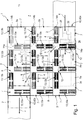
- FIG. 1 illustrates the positioning system 1 with a plurality of positioning slides 2, which are indicated for clarity only dash-dotted lines.
- the number of positioning slides 2 is basically arbitrary.
- the positioning system 1 can also be equipped with only a single positioning slide 2. References made below to a positioning slide 2 are to be understood as references to all positioning slides 2 present in each case.
- the slide carrier 3 expediently has a modular construction and is composed of a plurality of individual carrier modules 7. These carrier modules 7 can be connected in any arbitrary manner to form a two-dimensional module matrix in the x-y plane and, in particular, can also be mechanically coupled to one another, so that a coherent structure results.
- the carriage carrier 3 has a preferably plate-shaped main body structure 8.
- Each carrier module 7 has a main body 8a, wherein the carrier modules 7 with their basic bodies 8a are modularly stackable to each other, so that the plurality of juxtaposed main body 8a together form the main body structure 8.
- each base body 8a has a rectangular floor plan. This rectangular plan is preferably square, which applies to the embodiment.
- each base body 8a has four mutually perpendicular lateral outer surfaces 12 which define the ground plan of the base body 8a.
- the carrier modules 7 are aligned so that in each case two opposite lateral outer surfaces 12 are oriented in the x-axis direction and the other two opposite lateral outer surfaces 12 in the y-axis direction.
- the carrier modules 7 with the lateral outer surfaces 12 of their base body 8a are each anRATandbar set or juxtaposed.
- a slide carrier 3 can be formed, which is composed of any number of carrier module rows 7 running in the x-axis direction and any number of carrier module rows running in the y-axis direction.
- each of the four lateral outer surfaces 12 is suitable for the cultivation of a further carrier module 7, so that not only regular but also irregular distribution patterns of carrier modules 7 can be realized.
- the carriage carrier 3 is equipped with a plurality of gears, which fulfill a drive function with respect to the positioning carriage 2 and are therefore designated as drive gears 13. At least one of the drive gears 13 is responsible for a displacement of the positioning carriage 2 in the x-axis direction and is therefore referred to as x-drive gear 13a. At least one other drive gear 13 is responsible for a displacement of the positioning carriage 2 in the y-axis direction and is therefore designated as the y-drive gear 13b.
- Each x-drive gear 13a is rotatable relative to the main body structure 8 about a first axis of rotation 14a parallel to the y-axis.
- Each y-drive gear 13b is rotatable relative to the main body structure 8 about a second axis of rotation 14b parallel to the x-axis. All drive gears 13 are rotatably supported directly or indirectly on the main body structure 8.
- Each drive gear 13 has at its peripheral outer periphery via a hereinafter referred to as drive teeth 15 external teeth. These are in each case a straight toothing, wherein each tooth 15a of the drive toothing 15 and each tooth space 15b located between two teeth 15a of the drive toothing 15 has a longitudinal extent parallel to the associated rotation axis 14a, 14b.
- the drive toothing 15 is axially segmented and has two axially spaced apart toothing sections 15 ', 15 ", which is related to the fact that for generating a rotational movement 16 of the respective drive gear 13 torque required in the between the two gear sections 15th ', 15 "trained gap 15''' is introduced into the drive gear 13. Another introduction of the rotational movement 16 causing torque is also possible.
- All drive gears 13 are arranged so that they protrude with at least one peripheral portion of their drive teeth 15 on the carrier top 6 on the main body structure 8. These upwardly projecting peripheral portions of the drive gears 15 are the actual drive portions 17 of the drive gears 13 which cooperatively drive with the positioning carriage 2.
- the drive gears 13 are aligned overall so that all drive sections 17 lie in a common x-y plane, ie in a plane parallel to the positioning plane 5.
- Each positioning slide 2 is ahead with an underside 18 according to arrow 22 in FIG. 6 attached to the carriage carrier 3 from above.
- the underside 18 of the positioning slide 2 and the carrier top 6 of the slide carrier 3 in a direction perpendicular to the xy plane height direction, which could also be referred to as z-axis direction, facing each other.
- the positioning carriage 2 has on its underside 18 a tooth structure, which - because it serves the output of the positioning slide 2 - as output-tooth structure 23 is called.
- This output toothing structure 23 is in meshing engagement with the drive section 17 of the drive toothing 15 of at least one x drive gearwheel 13a and at least one y drive gearwheel 13b in each relative position of the positioning carriage 2 with respect to the carriage carrier 3 in the positioning plane 5.
- the first-time meshing engagement is very easy to produce directly at the vertical attachment of the positioning slide 2 to the slide carrier 3.
- the slide carrier 3 can be equipped in this way very time-saving with any number of positioning slide 2.
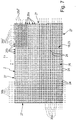
- the output gear structure 23 has a specific configuration. It has a plurality of output teeth 24 formed in the manner of projections, which are punctiformly arranged in the x-y plane with a regular two-dimensional distribution. All output teeth 24 together thus define a two-dimensional tooth matrix 25, which is composed of a plurality of each of a plurality of output teeth containing linear rows of teeth each extending in the x-axis direction and which are arranged in the y-axis direction with mutually equal distance side by side ,
- the individual output teeth 24 are at the crossing points of an in FIGS. 7 and 8th and having a plurality of mutually parallel y-grid lines 30b and the x-grid lines 30a are grid lines extending in the x-axis direction and the y-grid lines 30b is about running in the y-axis direction grid lines.
- the x-grid lines 30a intersect the y-grid lines 30b at right angles and are all in one and the same xy-plane.
- the mutual distance between the respectively adjacent x-grid lines 30a is preferably the same, as is the mutual distance between the respectively adjacent y-grid lines 30b.
- the distance between the respectively adjacent x-grid lines 30a is also the same size as the mutual distance between the respectively adjacent y-grid lines 30b.
- Each output tooth 24 is identically spaced with respect to the output teeth 24 adjacent to it in the x-axis direction and in the y-axis direction.
- the drive teeth 24 are designed, for example, knob-shaped or frusto-conical or truncated pyramidal.
- the shape of a truncated pyramid is expediently based on a regular four-sided pyramidal shape.
- each extends in the x-axis direction extending groove-like depression, which is designated due to their orientation as x-recess 26a.
- Each of these x-wells 26a has a longitudinal axis 26a 'extending in the x-axis direction.
- adjacent rows of teeth of output teeth 24 - which are also referred to as y rows of teeth - a running in the y-axis direction groove-like depression, which is referred to as y-recess 26b.
- Each y-well 26b has a longitudinal axis 26b 'extending in the y-axis direction. All x recesses 26a and also all y recesses 26b extend in an x-y plane parallel to the positioning plane 5, wherein they are expediently arranged in a common xy plane.
- the output gear tooth structure 23 expediently has a rectangular outer contour in the x-y plane.
- the positioning carriage 2 seen in plan view has a rectangular outline, wherein the driven toothing structure 23 extends to all four lateral edge regions 27 of the positioning carriage 2.
- the output gear structure 23 is unlimited at all four edge regions 27, which means that both the x-wells 26a and the y-depressions 26b are open at the front.
- the x-drive gear 13a set in rotation, it moves due to the meshing engagement the positioning slide 2 in the x-axis direction, at the same time the interdental spaces 15b of the y-drive gear 13b act as guide grooves in which the driven teeth 24 engaging in it guided linearly are.
- a rotational movement 16 of the y-drive gear 13 b a positioning movement of the 4 Positioning slide 2 in the y-axis direction, wherein the drive teeth 15 of the x-drive gear 13a in conjunction with the engaging them in output teeth 24 causes a linear guide of the positioning carriage 2 in the y-axis direction.
- the slide carrier 3 is equipped with its own drive means 28 for each drive gear 13. With the aid of these drive means 28, the associated drive gear 13 can be driven either clockwise or counterclockwise to the rotational movement 16, and preferably also with variable rotational speed.
- the direction of the positioning movement 4 can be specified. In this way, not only is it possible to move a positioning carriage 2 selectively in the x-axis direction or in the y-axis direction, but also with any other direction of movement and movement within the positioning plane 5.
- the drive means 28 are preferably of an electromotive nature and consist, for example, per drive gearwheel 13 of an electric motor designed as a stepping motor or as a servomotor.
- the driving coupling with the associated drive gear 13 is done for example via a rotatably driven drive screw 28a, which is in engagement with a worm wheel 28b of the drive gear 13 placed in the intermediate space 15 '' '.
- the fact that the drive gears 13 are driven independently of one another in rotation also makes it possible to arrange a plurality of positioning carriages 2 simultaneously on a carriage carrier 3 equipped with a plurality of x drive gears 13a and with a plurality of y drive gears 13b to move and position independently of each other.
- the punctual distribution of the output teeth 24 at the crossing points of a regular cross-grating makes it possible that the same output teeth 24 in the positioning movement 4 of the positioning carriage 2 can alternatively mesh with both an x-drive gear 13 a and a y-drive gear 13 b in meshing.
- each output tooth 24 is at no time in simultaneous engagement with an x-drive gear 13a and a y-drive gear 13b.
- the driven teeth 24 are each capable of being temporarily engaged in the positioning movement 4 with an x-drive gear 13a and then temporarily with a y-drive gear 13b.
- the output teeth 24 of the output gear structure 23 are not specifically associated with either an x drive gear 13a or a y drive gear 13b, but may cooperatively drive with both an x drive gear 13a and a y drive gear 13b depending on the position of the positioning carriage 2 , This results in a relatively large positioning range in the xy plane for the positioning slide 2 even with relatively short-throwing drive gears 13.
- the positioning range of the positioning carriage 2 is not predetermined by the size of the drive gears 13, but by the areal extent of the tooth matrix 25.
- the positioning slide 2 can readily assume positions during its positioning movement in which it passes over the side edge of the slide carrier 3 protrudes a carrier module 7.
- all drive gears 13 of the carriage carrier 3 in comparison to each other have the same diameter.
- the axes of rotation 14a, 14b of all the same diameter having drive gears 13 lie in a common, designated as axis plane 32 level, which is aligned parallel to the positioning plane 5.
- a positioning system 1 with only a single x-drive gear 13a and only a single y-drive gear 13b.
- Such a positioning system 1 then has, for example, the basis of the FIGS. 2 to 8 illustrated structure, wherein the carrier module 7 shown here then forms the entire slide carrier 3, which is designed as a unit.
- the particular advantage of the positioning system 1 manifests itself, however, especially when the slide carrier 3 is equipped with a plurality of x-drive gears 13a and / or with a plurality of y-drive gears 13b, wherein it preferably has both a plurality of x-drive gears 13a as well as a plurality of y-drive gears 13b. The latter applies to the in FIG. 1 illustrated embodiment to.
- FIG. 1 illustrated positioning system 1 has the already mentioned modular construction with a plurality in an xy plane
- Each of these carrier modules 7 has a main body 8a and two drive gears 13, one of which is an x-drive gear 13a and the other is a y-drive gear 13b.
- These two drive gears 13, 13a, 13b form a drive gear pair, which preferably has an L-shaped configuration.
- the axis of rotation 14a of the x-drive gear 13a lies on the one L-leg, while the axis of rotation 14b of the y-drive gear 13b lies on the other L-leg of the L-shaped configuration.
- an axial end portion 33a of the x-driving gear 13a is disposed adjacent to an axial end portion 33b of the y-driving gear 13b.
- the two drive gears 13 are placed within the outline of the main body 8a such that each drive gear 13 extends adjacent to and along one of two lateral outer surfaces 12 of the main body 8a that meet in a corner region of the main body 8a.
- the area lying between the two drive gears 13, 13 a, 13 b is optimally usable for accommodating the drive means 28.
- the various carrier modules 7 are formed identical to each other. They are also preferably lined up with each other so that the orientation of their drive gears 13 is equal to each other.
- such an arrangement of drive gears 13 preferably results in several mutually perpendicular rows of x drive gears 13a and y drive gears 13b.
- the Slide carrier 3 expediently several extending in the x-axis gear rows, which are spaced apart in the y-axis direction and whose drive gears 13 consist of y-drive gears 13b, which are arranged axially successive with coaxial longitudinal axes.
- the slide carrier 3 includes a plurality of y-axis extending, x-axis spaced apart rows of drive gears 13, which are all x-drive gears 13a, which are also coaxial and spaced apart from one another within the respective gear train are arranged.
- Such an arrangement can be realized in a modular structure in that the same design support modules 7 are aligned with each other with the same orientation two-dimensionally.
- the described multiple equipment of the slide carrier 3 with drive gears 13 has the advantageous effect that the positioning carriage 2 can be moved in a very large positioning range.
- One and the same positioning slide 2 can change its output cooperation with the individual drive wheels 13.
- the positioning carriage 2 can thus be handed over quasi during the positioning movement 4 between individual drive gears 13.
- the positioning carriage 2 can travel longer distances on different trajectories. This allows a particularly flexible use of the positioning system. 1
- each transfer station 42 is expediently provided by one of the Carrier modules 7 defined.
- a transfer station 42 is a delivery station 42a, on which positioning carriages 2 can be successively fed onto the carriage carrier 3 from outside the positioning system 1.
- Such positioning carriages 2 have been equipped, for example, outside the positioning system 1 with one or more products, which are moved within the positioning system 1 by corresponding method of the associated positioning carriage 2 in workstations where they experience any kind of processing or processing.
- At least one further transfer station 42 may be a discharge station 42b from which positioning carriages 2 equipped with at least one or more products or emptied positioning carriages 2 can be removed from the carriage carrier 3.
- each positioning carriage 2 When positioning within the positioning system 1, each positioning carriage 2 can in principle be moved across all existing carrier modules 7 away.
- a suitable monitoring system is provided, which is suitable for a seamless transition of the positioning carriage 2 between the ensures individual drive gears 13 and ensures that the current position of the positioning carriage 2 is known, so that by selective control of the drive gears 13, the desired positioning movement 4 of the positioning carriage 2 can be generated.
- the drive means 28 are expediently equipped with a suitable sensor which allows conclusions to the current rotational position of the associated drive gear 13 to drive based on this information a positioning slide 2 as desired and to position.
- each carrier module 7 is expediently electrically controllable in order to carry out the desired positioning movements.
- the carrier modules 7 are expediently at least electrically interconnected or networked in order to carry out an energy transmission and / or data transmission and / or signal transmission, which is required in particular for the positioning movement 4 of a positioning carriage 2.
- dotted is a corresponding network indicated 34, which is coupled to a not further illustrated external electronic control device and through which all the carrier modules 7 are electrically interconnected. If it is a non-modular slide carrier 3, with the help of such a network 34 also all existing drive means 28 and possibly existing sensor means can be networked in order to realize a central control and query function can.
- each carrier module 7 expediently contains such a decentralized electronic control unit 35.
- each carrier module 7 is expediently associated with suitable electromechanical interface means which permit a simple coupling to produce the desired network connection during assembly of the slide carrier 3.
- the slide carrier 3 can be equipped at one or more points with sensor means, which enable a position detection of at least one positioning slide 2, and suitably separated for the current position in the x-axis direction and the current position in the y-axis direction.
- Corresponding position detection means can work in particular on an optical basis.
- the positioning carriages 2 can be used to carry products that are to be supplied directly to a specific purpose or to accommodate separate product carriers that can be loaded with products.
- One possible application is the use of the positioning slide 2 for supporting so-called microtiter plates, which are used in laboratory automation to store fluid samples.
- the positioning carriage 2 - in particular on its underside 18 - can be provided with a readable coding which permits product identification and that of a slide carrier 3, for example a specific location or arranged at several locations identification device readable is. Such coding can also be used for position control.
- the positioning system 1 can also be equipped with RFID identification means, in particular in the region of a feed station 42a and a discharge station 42b.
- the positioning system 1 can also be equipped with electronic means that enable the execution of a teach mode.
- microswitches can be present at one or more locations of the slide carrier 3, which activate a teach mode when approaching a positioning slide 2 and report the current position of the positioning slide 2 to a control software.
- An advantage of the positioning system 1 is that the positioning surface which can be used for positioning the positioning carriage 2 can be substantially larger than the base area of the carriage carrier 3. In this way, the structure of the positioning system 1 takes up relatively little space.
- a compact three-dimensional product storage system can be realized.
- a plurality of positioning systems 1 in the manner of a shelving system can be placed vertically one above the other at a distance from one another, wherein they are each capable of simultaneously receiving a larger number of positioning carriages 2.
- This positioning slide 2 act here, for example, as storage pallets that can be stored as needed and also outsourced again.
- positioning 1 can be easily approached from the side.
Landscapes
- Engineering & Computer Science (AREA)
- Mechanical Engineering (AREA)
- General Engineering & Computer Science (AREA)
- Transmission Devices (AREA)
- Retarders (AREA)
- Character Spaces And Line Spaces In Printers (AREA)
Priority Applications (1)
| Application Number | Priority Date | Filing Date | Title |
|---|---|---|---|
| EP17175728.9A EP3260232B1 (fr) | 2014-08-06 | 2014-08-06 | Système de positionnement |
Applications Claiming Priority (2)
| Application Number | Priority Date | Filing Date | Title |
|---|---|---|---|
| EP17175728.9A EP3260232B1 (fr) | 2014-08-06 | 2014-08-06 | Système de positionnement |
| EP14002756.6A EP2982472B1 (fr) | 2014-08-06 | 2014-08-06 | Système de positionnement |
Related Parent Applications (2)
| Application Number | Title | Priority Date | Filing Date |
|---|---|---|---|
| EP14002756.6A Division EP2982472B1 (fr) | 2014-08-06 | 2014-08-06 | Système de positionnement |
| EP14002756.6A Division-Into EP2982472B1 (fr) | 2014-08-06 | 2014-08-06 | Système de positionnement |
Publications (2)
| Publication Number | Publication Date |
|---|---|
| EP3260232A1 true EP3260232A1 (fr) | 2017-12-27 |
| EP3260232B1 EP3260232B1 (fr) | 2018-11-07 |
Family
ID=51301105
Family Applications (2)
| Application Number | Title | Priority Date | Filing Date |
|---|---|---|---|
| EP17175728.9A Active EP3260232B1 (fr) | 2014-08-06 | 2014-08-06 | Système de positionnement |
| EP14002756.6A Active EP2982472B1 (fr) | 2014-08-06 | 2014-08-06 | Système de positionnement |
Family Applications After (1)
| Application Number | Title | Priority Date | Filing Date |
|---|---|---|---|
| EP14002756.6A Active EP2982472B1 (fr) | 2014-08-06 | 2014-08-06 | Système de positionnement |
Country Status (3)
| Country | Link |
|---|---|
| US (1) | US9751175B2 (fr) |
| EP (2) | EP3260232B1 (fr) |
| CN (1) | CN105364507B (fr) |
Families Citing this family (15)
| Publication number | Priority date | Publication date | Assignee | Title |
|---|---|---|---|---|
| EP3260232B1 (fr) * | 2014-08-06 | 2018-11-07 | FESTO AG & Co. KG | Système de positionnement |
| DE102016211093A1 (de) | 2016-06-22 | 2017-12-28 | Festo Ag & Co. Kg | Arbeitsvorrichtung |
| JP7052995B2 (ja) * | 2017-11-13 | 2022-04-12 | Necエンベデッドプロダクツ株式会社 | 搬送システム、制御装置、制御方法及びプログラム |
| US10689202B2 (en) | 2018-05-29 | 2020-06-23 | The Procter And Gamble Company | Apparatus for controlled transport of articles along a path |
| US10717606B2 (en) | 2018-05-29 | 2020-07-21 | The Procter And Gamble Company | Method of independently controlling motion of movers along a path |
| US10696488B2 (en) | 2018-05-29 | 2020-06-30 | The Procter And Gamble Company | Apparatus that controls motion of proximate independent movers along a path |
| US10919705B2 (en) | 2018-05-29 | 2021-02-16 | The Procter And Gamble Company | Apparatus that controls motion of independent movers along a path |
| US10633194B2 (en) | 2018-06-21 | 2020-04-28 | Thermal Product Solutions | Conveyance system with variable speed rollers |
| DE102018213857B4 (de) * | 2018-08-17 | 2020-07-16 | Festo Se & Co. Kg | Positioniersystem |
| DE102019201714A1 (de) | 2019-02-11 | 2019-05-09 | Festo Ag & Co. Kg | Positioniersystem zur Positionierung eines Positionierschlittens und Verfahren zum Betreiben eines Schlittenträgers in einem Positioniersystem |
| JP2020169081A (ja) * | 2019-04-02 | 2020-10-15 | Necエンベデッドプロダクツ株式会社 | 搬送装置及び搬送方法 |
| DE102020201559A1 (de) * | 2020-02-07 | 2021-08-12 | Festo Se & Co. Kg | Positioniersystem |
| CN113939117B (zh) * | 2020-06-29 | 2023-06-02 | 戴尔产品有限公司 | 用于模块化信息处理资源的齿轮系侧闩锁机构 |
| CN111774595A (zh) * | 2020-07-22 | 2020-10-16 | 吴功城 | 一种多轴联动的智能卧式开孔机 |
| FR3160169B1 (fr) * | 2024-03-14 | 2026-03-20 | Galam Robotics | Systeme de deplacement bidimensionnel d’un casier dans une strucutre modulaire de stockage |
Citations (3)
| Publication number | Priority date | Publication date | Assignee | Title |
|---|---|---|---|---|
| DE1920556A1 (de) | 1968-04-29 | 1969-11-20 | Texas Instruments Inc | Zweidimensional verstellbare Tischplatte |
| JPH10267100A (ja) | 1997-03-24 | 1998-10-06 | Teru Hayashi | 伝達機構 |
| JP2006308525A (ja) * | 2005-05-02 | 2006-11-09 | Nippon Telegr & Teleph Corp <Ntt> | 移動システム |
Family Cites Families (6)
| Publication number | Priority date | Publication date | Assignee | Title |
|---|---|---|---|---|
| JPS55134414A (en) * | 1979-04-06 | 1980-10-20 | Hitachi Ltd | Precise moving unit |
| US6637737B1 (en) * | 2002-07-31 | 2003-10-28 | Unova Ip Corp. | Workpiece micro-positioning apparatus |
| KR100677511B1 (ko) | 2005-08-12 | 2007-02-02 | 엘지전자 주식회사 | Bcast서비스 시스템 및 이를 이용한 콘텐츠 전송방법 |
| JP5119001B2 (ja) * | 2008-02-28 | 2013-01-16 | 株式会社日立ハイテクノロジーズ | 試料ステージ |
| WO2009142133A1 (fr) * | 2008-05-19 | 2009-11-26 | 株式会社アルバック | Etage |
| EP3260232B1 (fr) * | 2014-08-06 | 2018-11-07 | FESTO AG & Co. KG | Système de positionnement |
-
2014
- 2014-08-06 EP EP17175728.9A patent/EP3260232B1/fr active Active
- 2014-08-06 EP EP14002756.6A patent/EP2982472B1/fr active Active
-
2015
- 2015-07-17 US US14/802,052 patent/US9751175B2/en active Active
- 2015-08-06 CN CN201510476214.0A patent/CN105364507B/zh active Active
Patent Citations (3)
| Publication number | Priority date | Publication date | Assignee | Title |
|---|---|---|---|---|
| DE1920556A1 (de) | 1968-04-29 | 1969-11-20 | Texas Instruments Inc | Zweidimensional verstellbare Tischplatte |
| JPH10267100A (ja) | 1997-03-24 | 1998-10-06 | Teru Hayashi | 伝達機構 |
| JP2006308525A (ja) * | 2005-05-02 | 2006-11-09 | Nippon Telegr & Teleph Corp <Ntt> | 移動システム |
Also Published As
| Publication number | Publication date |
|---|---|
| EP2982472A1 (fr) | 2016-02-10 |
| EP3260232B1 (fr) | 2018-11-07 |
| US9751175B2 (en) | 2017-09-05 |
| CN105364507A (zh) | 2016-03-02 |
| CN105364507B (zh) | 2018-12-25 |
| EP2982472B1 (fr) | 2017-09-13 |
| US20160039061A1 (en) | 2016-02-11 |
Similar Documents
| Publication | Publication Date | Title |
|---|---|---|
| EP3260232B1 (fr) | Système de positionnement | |
| AT398923B (de) | Fertigungsanlage mit parallel- und nebenförderwegen | |
| DE2501381A1 (de) | Rationelle gamma-bestrahlungsanlage | |
| WO2017025137A1 (fr) | Système de positionnement avec agencement d'enroulement | |
| WO2017025136A1 (fr) | Système de positionnement pourvu d'un ensemble d'aimants | |
| DE2950292A1 (de) | Einrichtung zum ausrichten und festspannen eines werkstuecktraegers | |
| CH649238A5 (de) | Tafelzufuehrungseinrichtung an scheren. | |
| DE60106950T2 (de) | Werkzeugwechsler zur zu- und abführung von werkzeugen eines maschinenzentrums | |
| DE102019100806A1 (de) | Plattensägemaschine | |
| DE102016004335B4 (de) | Transporteinrichtung und Verfahren zum Transport von Objekten von Arbeitsstation zu Arbeitsstation einer Produktionsanlage und Produktionsanlage zur Herstellung von Produkten mit einer derartigen Transporteinrichtung | |
| EP0782175A2 (fr) | Appareil de manipulation d'objets en forme de disque | |
| WO2007128667A1 (fr) | Dispositif conçu pour usiner des composants d'une carrosserie d'automobile | |
| EP3798156B1 (fr) | Système de stockage et de retrait des récipients | |
| DE3725217C2 (fr) | ||
| DE2354462A1 (de) | Vorrichtung zum positionieren eines gegenstandes nacheinander gegenueber einer anzahl von behandlungsstationen | |
| EP1216787B1 (fr) | Dispositif de positionnement | |
| DE2017030B2 (de) | Vorrichtung zum schrittweisen Vorbeiführen von Probengefäßen an einer Prüfstation | |
| DE3718925C2 (fr) | ||
| EP3377276B1 (fr) | Dispositif de manipulation de liquide | |
| EP2832469A2 (fr) | Dispositif de manipulation de pièces à usiner ainsi qu'installation mécanique dotée d'un tel dispositif | |
| DE102009029664A1 (de) | Übertragungsmodul zur Übertragung von Teilen zwischen Stationen | |
| DE3540016A1 (de) | Gewerblicher montageroboter | |
| DE102017001828B3 (de) | Transporteinrichtung zum Transport von Objekten von Arbeitsstation zu Arbeitsstation einer Produktionsanlage und Produktionsanlage zur Herstellung von Produkten mit einer derartigen Transporteinrichtung | |
| EP2823933B1 (fr) | Agencement de stockage d'outils pour l'extension de la capacité de stockage d'outils d'un centre d'usinage par forage, fraisage et/ou tournage | |
| DE10064523A1 (de) | Anlage zur Bearbeitung von Werkstücken |
Legal Events
| Date | Code | Title | Description |
|---|---|---|---|
| PUAI | Public reference made under article 153(3) epc to a published international application that has entered the european phase |
Free format text: ORIGINAL CODE: 0009012 |
|
| STAA | Information on the status of an ep patent application or granted ep patent |
Free format text: STATUS: THE APPLICATION HAS BEEN PUBLISHED |
|
| AC | Divisional application: reference to earlier application |
Ref document number: 2982472 Country of ref document: EP Kind code of ref document: P |
|
| AK | Designated contracting states |
Kind code of ref document: A1 Designated state(s): AL AT BE BG CH CY CZ DE DK EE ES FI FR GB GR HR HU IE IS IT LI LT LU LV MC MK MT NL NO PL PT RO RS SE SI SK SM TR |
|
| STAA | Information on the status of an ep patent application or granted ep patent |
Free format text: STATUS: REQUEST FOR EXAMINATION WAS MADE |
|
| 17P | Request for examination filed |
Effective date: 20171222 |
|
| RBV | Designated contracting states (corrected) |
Designated state(s): AL AT BE BG CH CY CZ DE DK EE ES FI FR GB GR HR HU IE IS IT LI LT LU LV MC MK MT NL NO PL PT RO RS SE SI SK SM TR |
|
| GRAP | Despatch of communication of intention to grant a patent |
Free format text: ORIGINAL CODE: EPIDOSNIGR1 |
|
| STAA | Information on the status of an ep patent application or granted ep patent |
Free format text: STATUS: GRANT OF PATENT IS INTENDED |
|
| INTG | Intention to grant announced |
Effective date: 20180618 |
|
| GRAS | Grant fee paid |
Free format text: ORIGINAL CODE: EPIDOSNIGR3 |
|
| GRAA | (expected) grant |
Free format text: ORIGINAL CODE: 0009210 |
|
| STAA | Information on the status of an ep patent application or granted ep patent |
Free format text: STATUS: THE PATENT HAS BEEN GRANTED |
|
| AC | Divisional application: reference to earlier application |
Ref document number: 2982472 Country of ref document: EP Kind code of ref document: P |
|
| AK | Designated contracting states |
Kind code of ref document: B1 Designated state(s): AL AT BE BG CH CY CZ DE DK EE ES FI FR GB GR HR HU IE IS IT LI LT LU LV MC MK MT NL NO PL PT RO RS SE SI SK SM TR |
|
| REG | Reference to a national code |
Ref country code: GB Ref legal event code: FG4D Free format text: NOT ENGLISH |
|
| REG | Reference to a national code |
Ref country code: CH Ref legal event code: EP Ref country code: AT Ref legal event code: REF Ref document number: 1061495 Country of ref document: AT Kind code of ref document: T Effective date: 20181115 |
|
| REG | Reference to a national code |
Ref country code: DE Ref legal event code: R096 Ref document number: 502014010023 Country of ref document: DE |
|
| REG | Reference to a national code |
Ref country code: IE Ref legal event code: FG4D Free format text: LANGUAGE OF EP DOCUMENT: GERMAN |
|
| REG | Reference to a national code |
Ref country code: NL Ref legal event code: MP Effective date: 20181107 |
|
| REG | Reference to a national code |
Ref country code: LT Ref legal event code: MG4D |
|
| PG25 | Lapsed in a contracting state [announced via postgrant information from national office to epo] |
Ref country code: NO Free format text: LAPSE BECAUSE OF FAILURE TO SUBMIT A TRANSLATION OF THE DESCRIPTION OR TO PAY THE FEE WITHIN THE PRESCRIBED TIME-LIMIT Effective date: 20190207 Ref country code: HR Free format text: LAPSE BECAUSE OF FAILURE TO SUBMIT A TRANSLATION OF THE DESCRIPTION OR TO PAY THE FEE WITHIN THE PRESCRIBED TIME-LIMIT Effective date: 20181107 Ref country code: LT Free format text: LAPSE BECAUSE OF FAILURE TO SUBMIT A TRANSLATION OF THE DESCRIPTION OR TO PAY THE FEE WITHIN THE PRESCRIBED TIME-LIMIT Effective date: 20181107 Ref country code: IS Free format text: LAPSE BECAUSE OF FAILURE TO SUBMIT A TRANSLATION OF THE DESCRIPTION OR TO PAY THE FEE WITHIN THE PRESCRIBED TIME-LIMIT Effective date: 20190307 Ref country code: LV Free format text: LAPSE BECAUSE OF FAILURE TO SUBMIT A TRANSLATION OF THE DESCRIPTION OR TO PAY THE FEE WITHIN THE PRESCRIBED TIME-LIMIT Effective date: 20181107 Ref country code: ES Free format text: LAPSE BECAUSE OF FAILURE TO SUBMIT A TRANSLATION OF THE DESCRIPTION OR TO PAY THE FEE WITHIN THE PRESCRIBED TIME-LIMIT Effective date: 20181107 Ref country code: BG Free format text: LAPSE BECAUSE OF FAILURE TO SUBMIT A TRANSLATION OF THE DESCRIPTION OR TO PAY THE FEE WITHIN THE PRESCRIBED TIME-LIMIT Effective date: 20190207 Ref country code: FI Free format text: LAPSE BECAUSE OF FAILURE TO SUBMIT A TRANSLATION OF THE DESCRIPTION OR TO PAY THE FEE WITHIN THE PRESCRIBED TIME-LIMIT Effective date: 20181107 |
|
| PG25 | Lapsed in a contracting state [announced via postgrant information from national office to epo] |
Ref country code: GR Free format text: LAPSE BECAUSE OF FAILURE TO SUBMIT A TRANSLATION OF THE DESCRIPTION OR TO PAY THE FEE WITHIN THE PRESCRIBED TIME-LIMIT Effective date: 20190208 Ref country code: RS Free format text: LAPSE BECAUSE OF FAILURE TO SUBMIT A TRANSLATION OF THE DESCRIPTION OR TO PAY THE FEE WITHIN THE PRESCRIBED TIME-LIMIT Effective date: 20181107 Ref country code: AL Free format text: LAPSE BECAUSE OF FAILURE TO SUBMIT A TRANSLATION OF THE DESCRIPTION OR TO PAY THE FEE WITHIN THE PRESCRIBED TIME-LIMIT Effective date: 20181107 Ref country code: NL Free format text: LAPSE BECAUSE OF FAILURE TO SUBMIT A TRANSLATION OF THE DESCRIPTION OR TO PAY THE FEE WITHIN THE PRESCRIBED TIME-LIMIT Effective date: 20181107 Ref country code: SE Free format text: LAPSE BECAUSE OF FAILURE TO SUBMIT A TRANSLATION OF THE DESCRIPTION OR TO PAY THE FEE WITHIN THE PRESCRIBED TIME-LIMIT Effective date: 20181107 Ref country code: PT Free format text: LAPSE BECAUSE OF FAILURE TO SUBMIT A TRANSLATION OF THE DESCRIPTION OR TO PAY THE FEE WITHIN THE PRESCRIBED TIME-LIMIT Effective date: 20190307 |
|
| PG25 | Lapsed in a contracting state [announced via postgrant information from national office to epo] |
Ref country code: IT Free format text: LAPSE BECAUSE OF FAILURE TO SUBMIT A TRANSLATION OF THE DESCRIPTION OR TO PAY THE FEE WITHIN THE PRESCRIBED TIME-LIMIT Effective date: 20181107 Ref country code: DK Free format text: LAPSE BECAUSE OF FAILURE TO SUBMIT A TRANSLATION OF THE DESCRIPTION OR TO PAY THE FEE WITHIN THE PRESCRIBED TIME-LIMIT Effective date: 20181107 Ref country code: CZ Free format text: LAPSE BECAUSE OF FAILURE TO SUBMIT A TRANSLATION OF THE DESCRIPTION OR TO PAY THE FEE WITHIN THE PRESCRIBED TIME-LIMIT Effective date: 20181107 Ref country code: PL Free format text: LAPSE BECAUSE OF FAILURE TO SUBMIT A TRANSLATION OF THE DESCRIPTION OR TO PAY THE FEE WITHIN THE PRESCRIBED TIME-LIMIT Effective date: 20181107 |
|
| REG | Reference to a national code |
Ref country code: DE Ref legal event code: R097 Ref document number: 502014010023 Country of ref document: DE |
|
| PG25 | Lapsed in a contracting state [announced via postgrant information from national office to epo] |
Ref country code: SK Free format text: LAPSE BECAUSE OF FAILURE TO SUBMIT A TRANSLATION OF THE DESCRIPTION OR TO PAY THE FEE WITHIN THE PRESCRIBED TIME-LIMIT Effective date: 20181107 Ref country code: RO Free format text: LAPSE BECAUSE OF FAILURE TO SUBMIT A TRANSLATION OF THE DESCRIPTION OR TO PAY THE FEE WITHIN THE PRESCRIBED TIME-LIMIT Effective date: 20181107 Ref country code: EE Free format text: LAPSE BECAUSE OF FAILURE TO SUBMIT A TRANSLATION OF THE DESCRIPTION OR TO PAY THE FEE WITHIN THE PRESCRIBED TIME-LIMIT Effective date: 20181107 Ref country code: SM Free format text: LAPSE BECAUSE OF FAILURE TO SUBMIT A TRANSLATION OF THE DESCRIPTION OR TO PAY THE FEE WITHIN THE PRESCRIBED TIME-LIMIT Effective date: 20181107 |
|
| PLBE | No opposition filed within time limit |
Free format text: ORIGINAL CODE: 0009261 |
|
| STAA | Information on the status of an ep patent application or granted ep patent |
Free format text: STATUS: NO OPPOSITION FILED WITHIN TIME LIMIT |
|
| 26N | No opposition filed |
Effective date: 20190808 |
|
| PG25 | Lapsed in a contracting state [announced via postgrant information from national office to epo] |
Ref country code: SI Free format text: LAPSE BECAUSE OF FAILURE TO SUBMIT A TRANSLATION OF THE DESCRIPTION OR TO PAY THE FEE WITHIN THE PRESCRIBED TIME-LIMIT Effective date: 20181107 |
|
| REG | Reference to a national code |
Ref country code: DE Ref legal event code: R082 Ref document number: 502014010023 Country of ref document: DE Representative=s name: OSTERTAG & PARTNER, PATENTANWAELTE MBB, DE |
|
| PG25 | Lapsed in a contracting state [announced via postgrant information from national office to epo] |
Ref country code: TR Free format text: LAPSE BECAUSE OF FAILURE TO SUBMIT A TRANSLATION OF THE DESCRIPTION OR TO PAY THE FEE WITHIN THE PRESCRIBED TIME-LIMIT Effective date: 20181107 |
|
| REG | Reference to a national code |
Ref country code: DE Ref legal event code: R082 Ref document number: 502014010023 Country of ref document: DE Representative=s name: OSTERTAG & PARTNER, PATENTANWAELTE MBB, DE Ref country code: DE Ref legal event code: R081 Ref document number: 502014010023 Country of ref document: DE Owner name: FEYRER + HAHN GMBH, DE Free format text: FORMER OWNER: FESTO AG & CO. KG, 73734 ESSLINGEN, DE |
|
| GBPC | Gb: european patent ceased through non-payment of renewal fee |
Effective date: 20190806 |
|
| PG25 | Lapsed in a contracting state [announced via postgrant information from national office to epo] |
Ref country code: LI Free format text: LAPSE BECAUSE OF NON-PAYMENT OF DUE FEES Effective date: 20190831 Ref country code: CH Free format text: LAPSE BECAUSE OF NON-PAYMENT OF DUE FEES Effective date: 20190831 Ref country code: MC Free format text: LAPSE BECAUSE OF FAILURE TO SUBMIT A TRANSLATION OF THE DESCRIPTION OR TO PAY THE FEE WITHIN THE PRESCRIBED TIME-LIMIT Effective date: 20181107 Ref country code: LU Free format text: LAPSE BECAUSE OF NON-PAYMENT OF DUE FEES Effective date: 20190806 |
|
| REG | Reference to a national code |
Ref country code: BE Ref legal event code: MM Effective date: 20190831 |
|
| PG25 | Lapsed in a contracting state [announced via postgrant information from national office to epo] |
Ref country code: IE Free format text: LAPSE BECAUSE OF NON-PAYMENT OF DUE FEES Effective date: 20190806 Ref country code: FR Free format text: LAPSE BECAUSE OF NON-PAYMENT OF DUE FEES Effective date: 20190831 |
|
| PG25 | Lapsed in a contracting state [announced via postgrant information from national office to epo] |
Ref country code: BE Free format text: LAPSE BECAUSE OF NON-PAYMENT OF DUE FEES Effective date: 20190831 Ref country code: GB Free format text: LAPSE BECAUSE OF NON-PAYMENT OF DUE FEES Effective date: 20190806 |
|
| REG | Reference to a national code |
Ref country code: AT Ref legal event code: MM01 Ref document number: 1061495 Country of ref document: AT Kind code of ref document: T Effective date: 20190806 |
|
| PG25 | Lapsed in a contracting state [announced via postgrant information from national office to epo] |
Ref country code: AT Free format text: LAPSE BECAUSE OF NON-PAYMENT OF DUE FEES Effective date: 20190806 |
|
| PG25 | Lapsed in a contracting state [announced via postgrant information from national office to epo] |
Ref country code: CY Free format text: LAPSE BECAUSE OF FAILURE TO SUBMIT A TRANSLATION OF THE DESCRIPTION OR TO PAY THE FEE WITHIN THE PRESCRIBED TIME-LIMIT Effective date: 20181107 |
|
| PG25 | Lapsed in a contracting state [announced via postgrant information from national office to epo] |
Ref country code: MT Free format text: LAPSE BECAUSE OF FAILURE TO SUBMIT A TRANSLATION OF THE DESCRIPTION OR TO PAY THE FEE WITHIN THE PRESCRIBED TIME-LIMIT Effective date: 20181107 Ref country code: HU Free format text: LAPSE BECAUSE OF FAILURE TO SUBMIT A TRANSLATION OF THE DESCRIPTION OR TO PAY THE FEE WITHIN THE PRESCRIBED TIME-LIMIT; INVALID AB INITIO Effective date: 20140806 |
|
| PG25 | Lapsed in a contracting state [announced via postgrant information from national office to epo] |
Ref country code: MK Free format text: LAPSE BECAUSE OF FAILURE TO SUBMIT A TRANSLATION OF THE DESCRIPTION OR TO PAY THE FEE WITHIN THE PRESCRIBED TIME-LIMIT Effective date: 20181107 |
|
| PGFP | Annual fee paid to national office [announced via postgrant information from national office to epo] |
Ref country code: DE Payment date: 20250821 Year of fee payment: 12 |