EP3260644B1 - Porte-verre et son procédé de montage - Google Patents
Porte-verre et son procédé de montage Download PDFInfo
- Publication number
- EP3260644B1 EP3260644B1 EP17000976.5A EP17000976A EP3260644B1 EP 3260644 B1 EP3260644 B1 EP 3260644B1 EP 17000976 A EP17000976 A EP 17000976A EP 3260644 B1 EP3260644 B1 EP 3260644B1
- Authority
- EP
- European Patent Office
- Prior art keywords
- glass holder
- leg
- contact pressure
- expanding element
- filling element
- Prior art date
- Legal status (The legal status is an assumption and is not a legal conclusion. Google has not performed a legal analysis and makes no representation as to the accuracy of the status listed.)
- Active
Links
Images


Classifications
-
- E—FIXED CONSTRUCTIONS
- E06—DOORS, WINDOWS, SHUTTERS, OR ROLLER BLINDS IN GENERAL; LADDERS
- E06B—FIXED OR MOVABLE CLOSURES FOR OPENINGS IN BUILDINGS, VEHICLES, FENCES OR LIKE ENCLOSURES IN GENERAL, e.g. DOORS, WINDOWS, BLINDS, GATES
- E06B3/00—Window sashes, door leaves, or like elements for closing wall or like openings; Layout of fixed or moving closures, e.g. windows in wall or like openings; Features of rigidly-mounted outer frames relating to the mounting of wing frames
- E06B3/54—Fixing of glass panes or like plates
-
- E—FIXED CONSTRUCTIONS
- E06—DOORS, WINDOWS, SHUTTERS, OR ROLLER BLINDS IN GENERAL; LADDERS
- E06B—FIXED OR MOVABLE CLOSURES FOR OPENINGS IN BUILDINGS, VEHICLES, FENCES OR LIKE ENCLOSURES IN GENERAL, e.g. DOORS, WINDOWS, BLINDS, GATES
- E06B3/00—Window sashes, door leaves, or like elements for closing wall or like openings; Layout of fixed or moving closures, e.g. windows in wall or like openings; Features of rigidly-mounted outer frames relating to the mounting of wing frames
- E06B3/54—Fixing of glass panes or like plates
- E06B3/58—Fixing of glass panes or like plates by means of borders, cleats, or the like
- E06B3/5807—Fixing of glass panes or like plates by means of borders, cleats, or the like not adjustable
- E06B3/5821—Fixing of glass panes or like plates by means of borders, cleats, or the like not adjustable hooked on or in the frame member, fixed by clips or otherwise elastically fixed
-
- E—FIXED CONSTRUCTIONS
- E06—DOORS, WINDOWS, SHUTTERS, OR ROLLER BLINDS IN GENERAL; LADDERS
- E06B—FIXED OR MOVABLE CLOSURES FOR OPENINGS IN BUILDINGS, VEHICLES, FENCES OR LIKE ENCLOSURES IN GENERAL, e.g. DOORS, WINDOWS, BLINDS, GATES
- E06B3/00—Window sashes, door leaves, or like elements for closing wall or like openings; Layout of fixed or moving closures, e.g. windows in wall or like openings; Features of rigidly-mounted outer frames relating to the mounting of wing frames
- E06B3/54—Fixing of glass panes or like plates
- E06B3/58—Fixing of glass panes or like plates by means of borders, cleats, or the like
-
- E—FIXED CONSTRUCTIONS
- E06—DOORS, WINDOWS, SHUTTERS, OR ROLLER BLINDS IN GENERAL; LADDERS
- E06B—FIXED OR MOVABLE CLOSURES FOR OPENINGS IN BUILDINGS, VEHICLES, FENCES OR LIKE ENCLOSURES IN GENERAL, e.g. DOORS, WINDOWS, BLINDS, GATES
- E06B3/00—Window sashes, door leaves, or like elements for closing wall or like openings; Layout of fixed or moving closures, e.g. windows in wall or like openings; Features of rigidly-mounted outer frames relating to the mounting of wing frames
- E06B3/54—Fixing of glass panes or like plates
- E06B3/58—Fixing of glass panes or like plates by means of borders, cleats, or the like
- E06B3/585—Fixing of glass panes or like plates by means of borders, cleats, or the like adjustable, e.g. for accommodating panes of various thickness, or with provisions for altering the clamping force on the pane
- E06B3/5857—Fixing of glass panes or like plates by means of borders, cleats, or the like adjustable, e.g. for accommodating panes of various thickness, or with provisions for altering the clamping force on the pane the fixing being adjustable, e.g. in one of several possible positions
- E06B3/5864—Fixing of glass panes or like plates by means of borders, cleats, or the like adjustable, e.g. for accommodating panes of various thickness, or with provisions for altering the clamping force on the pane the fixing being adjustable, e.g. in one of several possible positions with adjusting screws, wedges or cams
Definitions
- the invention relates to a method for positioning and/or holding a filling element and a glass holder as described in claims 1 and 7.
- a filling element and a glass holder as described in claims 1 and 7.
- a wide variety of methods and profile systems or glass holders for fixing the glass pane or the filling element are known, whereby particularly in passive houses there are increased demands on the tightness, which should be guaranteed even after years.
- wet glazing silicone is applied to the joints between the frame/metal profile and the filling element according to the width of the joint, and no pressure is required on the outer shell.
- the disadvantage of the old wet glazing system is that a specialist is required to apply the silicone, as poor-quality silicone cannot guarantee the joint will remain tight over its lifetime. A skilled worker is also required to produce a silicone joint that looks even.
- wet glazing cannot be carried out at temperatures below a certain level of 5°C.
- Another major disadvantage is that the glass strip or wooden strip that is arranged on the inside is usually destroyed when the pane is removed when the pane is replaced, so that new replacement strips usually look different, as the color of the glass strip (usually made of wood) changes over time due to UV radiation.
- a silicone sealing profile is attached both inside and outside instead of silicone.
- a corresponding pressure must be applied to the outer seal via the filling element so that it is tight and the filling element fits completely.
- this must also be guaranteed in the case of rain and wind pressure against the filling element, so that high demands are placed on the pressure-generating system or elements.
- the tightness achieved by simply pressing the filling element and then nailing a conventional glazing bead is usually insufficient, as glazing bead made of wood in particular is prone to shrinkage. cannot permanently guarantee the required contact pressure, which can lead to the system becoming leaky.
- a glass holder which is known with a spreading element, wherein the spreading element is attached to the base body via a flexible connection, in particular a tab.
- the glass holder is attached in such a way that a fastening means is attached, in particular screwed, through the spreading element and the base body, so that the spreading element is pressed against a pressing leg for positioning and/or holding the filling element or a flat structure in a frame of windows, doors and related devices.
- the spreading element is first positioned accordingly, after which the fastening means is then inserted into a hole in the spreading element and screwed in.
- the disadvantage here is that several steps are necessary to install the glass holder, for which the installer needs both hands, since the expansion element must first be positioned accordingly before the fastening device can be screwed in.
- the screw guide is designed as a two-part sliding body, with each sliding body part having a sliding surface designed as an inclined plane.
- the main disadvantages here are the guidance and positioning of the glass holder and the screw, which can lead to assembly errors or inaccuracies. For example, if you want to be able to adjust the contact pressure on the filling element, the arrangement of support feet that serve to ensure a firm hold and a predefined position is not possible because this would make it impossible to move the glass holder towards the filling element. Readjustment in the event of later material shrinkage is also not possible or only possible to a very small extent.
- a major disadvantage, however, is also the handling during assembly, since a specially developed gauge must be used to position the glass holder in order to achieve the correct distance between the glass holder and the filling element and to simplify the positioning of the sliding body part on the sliding surface.
- a glass holder which has a base body with a spreading element and a pressing leg.
- the base body is first fastened using a fastening means, in particular a screw, after which a spreading element is then inserted between the spreading element and the pressing element so that when it is driven into the receiving area, the pressure leg is pressed against the filling element.
- the expansion element is secured in the receiving area by means of a locking connection.
- the disadvantage here is that it is not easy to dismantle the expansion element or readjust it, and the glass holder, in particular the locking connection, is destroyed when an expansion element is removed.
- the assembly effort is also much higher, as the glass holder must first be screwed on using the fastening device before the expansion element can be hammered in.
- a glass retaining strip is shown that can be easily clipped onto the sash profile.
- the disadvantage here is that the contact pressure on the window glass is not adjustable and/or adjustable and, in particular, readjustment is not possible in the event of shrinkage or wear.
- coordinated profiles are required here and fastening to a standard frame in this way is not possible.
- such a system can usually not generate sufficient contact pressure on the outer silicone seal in the outer shell, so that in the event of strong wind pressure the filling element is pressed by the silicone seal and, if it rains at the same time, water can penetrate into the resulting gap.
- the filling element, in particular the window pane, in dry glazing of the type mentioned above is ideally sealed to the outer profile, in particular usually an aluminum shell, using a silicone foam seal.
- an appropriate contact pressure must be applied and ensured in order to guarantee the tightness between the sealing profile in the outer shell (outer seal) and the filling element, in particular the window pane.
- the disadvantage of the known systems is that after a longer period of use or service life, shrinkage in the individual profiles or frames or structures can occur, leading to reduced contact pressure on the outer seal and consequently to leaks in the window profile.
- Modern passive houses in particular with environmentally friendly energy return systems, living space ventilation, etc. are based on appropriately sealed window and door systems that should still be airtight and adjustable even after years.
- the present invention is based on the object of improving a method for positioning and/or holding a filling element and/or a glass holder for carrying out the method of the type mentioned at the beginning in such a way that simple production and assembly is achieved on the one hand and an adjustable and permanent contact pressure is achieved to achieve the best possible seal.
- a further object of the invention is to avoid the above-mentioned disadvantages.
- the object of the invention is achieved by a method for positioning and/or holding a filling element or a flat structure in a frame of windows, doors and related devices in such a way that the fastening takes place via a glass holder by placing the filling element on an outer shell and then attaching the glass holder to the frame on the opposite side of the filling element, wherein a spreading element is fastened to a base body of the glass holder via a predetermined breaking point or via an elastic or flexible connection, in particular a tab, wherein the spreading element is introduced into a receiving area between a support leg and a pressing leg and fastened via a fastening means, wherein the support leg and the pressing leg enclose an angle of between 1° and 65° to one another when the glass holder is not mounted, wherein this angle increases when the spreading element is inserted, wherein due to a displacement of the spreading element in the direction of a base of the glass holder or in the direction of the frame, a pressing force is generated by pivoting the pressing leg in the direction of the
- the advantage here is that the contact pressure is not achieved, as with conventional systems, primarily by slanting the screw towards the filling element, and thus depends heavily on the assembly skills and experience of the fitter or his mood on the day, but the fastening means or the screw is positioned or guided exactly normal to the frame or at a predefined angle, in particular at approximately the same angle as the support leg, and the contact pressure, in particular the screw-in depth of the expansion element, can be precisely adjusted.
- the glass holder is very easy to handle, since this or its base body is first placed on the frame to the filling element and then the expansion element is placed on top or, if the expansion element is attached, the fastening means is inserted so that it is guided over the base body of the glass holder, in particular a base, and the expansion element through corresponding holes or openings, so that only the fastening means has to be screwed in, preferably with a cordless screwdriver.
- the contact pressure can be adjusted based on the screw-in depth.
- measures in which an expansion element is released from a base body of the glass holder by fastening the fastening means are also advantageous. This ensures that the expansion element is held in position by the detachable connection and the fastening means, in particular a screw, can be easily inserted into the expansion element and screwed into the receiving area in a targeted or guided manner, with the expansion means automatically being released from the base body of the glass holder during this process.
- the profiles and position are optimally coordinated by the manufacturer and the contact pressure or the pivoting range of the contact leg can be precisely defined or adjusted on site.
- measures whereby the expansion element is attached to the base body via a predetermined breaking point are also advantageous, as this means that the expansion element is connected to the base body and positioned precisely, and no additional handling steps are required during assembly, such as manually inserting and aligning the expansion element or separating any connection between the base body and the expansion element.
- the expansion element is preferably detached from the base body via the fastening means, for example simply by screwing it in using a cordless screwdriver.
- This also enables very quick and error-free assembly of the glass holder, as the expansion element is held in the assembly position via the predetermined breaking point, so that only the glass holder preferably needs to be inserted into a groove. is positioned on the frame above the support foot, a screw must be inserted and preferably screwed in with the cordless screwdriver.
- the expansion element is not screwed all the way into the receiving area, i.e. up to the base, so that there is a free space between the base and the expansion element in the assembled state for subsequent fastening if shrinkage occurs. This ensures that if shrinkage or a leak occurs in the filling element, the fastening element can still be adjusted or screwed in further. It is also possible for visual symbols to be arranged on the expansion element so that corresponding specifications for assembly via the screw-in depth are possible. It is also possible for a stop for the optimal screw-in depth to be created by arranging a locking lug in the receiving area, over which the expansion element can be screwed in deeper with increased force.
- the force directed normal to the frame or slightly at an angle in the direction of the filling element, which arises during the fastening process, is advantageously diverted or redirected in the direction of the filling element.
- the contact pressure on the filling element can be increased by fastening the fastener more tightly and the contact pressure can be reduced by loosening the fastener bit by bit
- the preferred simple and effective adjustment and readjustment of the contact pressure to ensure a flat installation and tightness as well as thermal insulation of the window or door element is taken into account.
- measures are also advantageous for designing the expansion element in its cross-sectional shape so that it tapers at least on one side, in particular trapezoidal or wedge-shaped, since the spreading effect is optimized via the tapered design or the trapezoidal or wedge shape and its thickness can be precisely defined by means of the angular surface(s).
- the invention is also solved by a glass holder according to claim 7.
- the object of the invention is achieved by the glass holder in which a support leg and a pressure leg, with a pressure surface arranged thereon, are arranged on the glass holder to form a receiving area for the expansion element, wherein the support leg and the pressure leg form an angle of between 1° and 65° with respect to one another when the glass holder is not mounted, wherein this angle increases when the expansion element is inserted.
- the spreading effect on the two legs causes the expansion element to be deformed or pivoted, thus achieving a well-dosed and adjustable force transmission in the direction of the filling element, thereby fastening or fixing the filling element accordingly.
- a significant advantage lies above all in the fact that very high tolerances occur in the filling elements, in particular glass panes, in particular in the width of the filling element, which can be compensated for for the first time with the glass holder according to the invention.
- the filling elements in particular glass panes, in particular in the width of the filling element, which can be compensated for for the first time with the glass holder according to the invention.
- triple glazing there are up to +/- 1.2mm between the different panes of glass, but also within a pane of glass, whereby the panes of glass are usually thicker at the corners than in the middle due to production reasons.
- a corresponding structure is used for dry glazing, in which an external seal, in particular a silicone foam seal, is used by the applicant on the outside of the outer shell, in particular on the aluminum profile, which works together with the glass holder on the inside.
- the silicone foam seal can accommodate high tolerances of the filling element, whereby the glass holder generates the necessary contact pressure of the filling element on the external seal, in particular a silicone foam seal, via the expansion element by simply screwing in the fastening device.
- the glass holder can be used not only for passive house windows, but also for all wood or wood/aluminum windows.
- a design in which the expansion element is detachably attached or via a predetermined breaking point to the support leg and/or pressure leg enables easy installation.
- the glass holder is preferably plugged into a guide groove in the frame via the support foot, so that the latter is already positioned at the correct distance from the filling element.
- the support foot and the guide groove are ideally dimensionally coordinated in such a way that the glass holder remains firmly in place after being plugged into the guide groove, so that the glass holder does not fall out of the groove when installed overhead.
- the fastening device can then be inserted into the holes provided, as the expansion element is held in position via the predetermined breaking point, after which it only needs to be screwed on. Screwing it in automatically separates the predetermined breaking point, so that the expansion element is attached to the fastening device in the receiving area of the glass holder.
- the support leg By designing the support leg to be more dimensionally stable than the pressure leg, the pressure leg can be moved or pivoted in the direction of the filling element in an advantageous and simple manner. This also ensures that the support leg and the plug-in extensions for fastening the cladding profile, which are formed on the base body of the glass holder and preferably extend away from the filling element, remain precisely aligned.
- a design in which the fastening element is designed for variable adjustment of the distance or height between the expansion element and the base body, in particular the base of the glass holder, in particular as a screw element, is advantageous. This allows an exact relative adjustment to one another and thus also an exact contact force on the filling element.
- a design in which a support foot is arranged on the base body for insertion and positioning in a groove relative to the filling element is also advantageous. This ensures that the glass holder is arranged in the correct position relative to the filling element. At the same time, the glass holder is also held securely in the groove at the sides and at the top of the frame, making assembly considerably easier.
- a method for positioning and/or holding a filling element 1 or a flat structure in a frame of windows, doors and related devices with glazing and a glass holder 2 is shown.
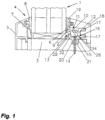
- FIG.1 a fully assembled fixation of the filling element 1 to a frame 3 by means of an outer shell 4 and glass holder 2 is shown.
- a metal profile 5, in particular an aluminum shell, can also be designed as the outer shell 4.
- the filling element 1 is placed or laid on the outer shell 4 and then the glass holder 2 is attached to the opposite side of the filling element 1 to fix it to the frame 3.
- the outer shell 4 thus serves as a stop for the filling element 1, which is pressed against the outer shell 4, in particular an outer seal, via a contact surface 6 of the glass holder 2, whereby a contact pressure is built up on the outside and inside of the filling element 1, in particular an outer seal or silicone seal consisting of a sealing body 7 made of silicone and a sealing head 8 made of silicone foam.
- the one-piece seal was shown in two parts in order to better distinguish between the different areas, whereby the sealing body 7 and the sealing head 8 are produced co-extruded and the sealing head can accommodate the high tolerance ranges of the filling element 1 due to the silicone foam used.
- a protective/sealing layer 9, i.e. an inner seal, is preferably applied to the contact surface 6 in order to prevent damage to the filling element 1 or water ingress on the inside.
- filling elements 1 are not limited to components made of glass, but other, preferably transparent, materials can also be used, such as acrylic glass, or metal panels, wood panels, etc.
- the method or glass holder 2 according to the invention is suitable for fastening to a wide variety of materials, with frames 3 made of wood, plastic, aluminum or composite profiles usually being used.
- the fastening or positioning and/or holding of the filling element 1 in the frame 3, in particular in a frame or sash of windows, doors and related devices with glazing, takes place via the glass holder 2, in particular a so-called dry glazing.
- the contact pressure of the glass holder 2 on the filling element 1 and thus from the filling element 1 to the outer seal is achieved or built up via a spreading element 10, which redirects the pressure or force applied during fastening in the direction of the frame 3 in the direction of the filling element 1.
- the expansion element 10 is introduced into a receiving area 11 between a support leg 12 and a pressing leg 13 and is fastened via a fastening means 14, whereby due to a displacement of the expansion element 10 in the direction of a base 15 of the glass holder 2 or in the direction of the frame 3, a pressing force is generated and adjusted by moving or pivoting the pressing leg 13 in the direction of the filling element 1.
- the contact pressure on the filling element 1 can be increased with a stronger fastening of the fastening means 14 and the Contact pressure can be reduced. This means that the deeper the expansion element 10 is screwed in, the higher the contact pressure is.
- a plug-in extension 17 is formed on a base body 16 of the glass holder 2, preferably in the direction facing away from the filling element 1, which is designed for the preferably detachable fastening of a cladding profile 18 or a glass strip.
- Fig.1 The embodiment shown has two plug-in extensions 17 for better positioning and sealing, which are aligned normally to the filling element 1.
- just one plug-in extension 17 can be used, the position of which is coordinated with the respective cladding profile 18 or glazing bead, or the reverse variant is also possible, namely arranging a plug-in extension receptacle on the glass holder 2, which can be brought into engagement with a plug-in extension on the cladding profile 18 or on the glazing bead.
- a further sealing profile 19, in particular an internal seal, is fixed between the cladding profile 18 and the filling element 1 in order to be able to seal the system on the inside as well.
- At least one support foot 20 is preferably formed on the base 15 of the glass holder 2 or the base body 16, which engages in a recess or groove 21 on the frame 3 or frame profile or is guided and fixed therein. This achieves better positioning in relation to the filling element 1 and dimensioning for more targeted alignment of the contact pressure as well as easier assembly and positioning of the cover profile. Displacement of the glass holder 2 when screwing in the fastening means 14 is thus avoided, and the glass holder 2 is also prevented from falling out of the sides or top of the frame 3.
- Such receiving grooves are usually already provided as standard on the inside of the glass in the frame 3 or frame profile, which is why different support foot dimensions are provided for the glass holder 2.
- Two support feet 20 are preferably arranged and formed at such a distance from one another that the distances on the outer edges are preferably 4 mm, 5 mm or 6 mm. However, other distances and dimensions of the support feet 20 are also possible, wherein the size and/or the distance is particularly adapted to the groove 21 in order to achieve a firm fit of the glass holder 2.
- the support foot 20 can be omitted entirely in order to achieve assembly on frames 3 on which no groove 21 is provided, i.e. that the glass holder 2 is simply placed on the frame 3 and during assembly is simply pressed lightly with the fingers, in particular the thumb, in the direction of the filling element 1, with the other hand, the fastening means 14 is preferably screwed in with a cordless screwdriver.
- Fig. 2 the glass holder 2 in its initial position with the expansion element 10 which is detachably connected to the glass holder 2 or to a base body 16 via a predetermined breaking point 35.
- the predetermined breaking point 35 is designed as a narrow web and holds the expansion element 10 in the initial position in position above the receiving area 11, i.e.
- the glass holder 2 is preferably manufactured in one piece, in which the expansion element 10 is fastened to the base body 16 via the predetermined breaking point 35 and only during fastening or assembly, in particular when screwing in the fastening means 14, is the expansion element 10 automatically released by the force of the fastening means 14, i.e. the predetermined breaking point 35 is separated to form the expansion element 10. This makes handling during assembly much easier.
- the glass holder 2 is shown in its initial position, with the expansion element 10 being detachably formed or attached to the base body 16.
- the expansion element 10 is attached in the receiving area 11, preferably, as shown, on the pressing leg 13.
- the expansion element 10 can also be attached at another location in the receiving area 11, for example on the supporting leg 12.
- the preferred design in which the expansion element 10 is only released from the base body 16 of the glass holder 2 when the fastening means 14 is fastened, makes assembly much easier. This is done in such a way that the glass holder 2 only needs to be inserted into the groove 21 and screwed on. Only the screw-in depth needs to be taken into account, as this defines or sets the contact pressure or contact force on the filling element 1. For this purpose, it is possible to set a special screw force when using a cordless screwdriver, with which the glass holder 2 is then fastened, so that the expansion element 10 is always screwed in to the same depth and thus always generates approximately the same force on the filling element 1.
- a hole 22 on the base 15 in the receiving area 11 for the fastening means 14 (in Fig. 2 not shown), in particular a screw, is provided, through which one end of the fastening means 14 is screwed into the frame 3.
- holes 23 or recesses are arranged on the contact surface 6, which can be used to apply a protective/sealing layer 9 or an internal seal.
- the bores 22 and holes 23 can also be designed as a threaded bore for a screw element or in another recess shape, for example square or as a slot.
- the expansion element 10 preferably has webs 24 to ensure dimensional stability when pressure is applied and recesses (25, 26), the expansion element 10 having approximately the shape of a trapezoid or rectangle.
- the recess 25 is mainly used to countersink the fastening means 14 or the screws, i.e. to accommodate the screw head so that it is flush with the expansion element 10.
- a contact surface 27 and the hole direction are designed in such a way that the fastening means 14 is guided in a manner coordinated with the receiving area 11 so that a correspondingly directed, uniform contact pressure of the contact surface 6 on the filling element 1 is achieved, whereby assembly errors can be avoided.
- the force which is essentially generated via the fastening means 14, or the force effect, is determined by means of an angular arrangement of insertion legs 28 of the Spreading element 10 and/or angular arrangement of the supporting and pressing legs (12, 13) is directed or redirected in the direction of the pressing leg 13 or filling element 1.
- the contact surface 27 or the hole guide can also be aligned in such a way that the pressure or the forces act more strongly in the direction of the pressing leg 13 and/or the expansion element 10 tilts in the direction of the pressing leg 13 after complete insertion and this is thereby pressed even further in the direction of the filling element 1.
- the former can be achieved, for example, by guiding the fastening means 14 at a slight angle in the direction of the filling element 1 and the latter by additional precautions on the expansion element 10, such as a bevel of the surface of the expansion element 10 that rests against the base 15, i.e. inclination in the direction of the pressing leg 13.
- the fastening means 14 is preferably guided over the recess 25 and bore 22 in such a way that the fastening means 14 is screwed into the frame 3 perpendicularly or normally to the frame 3 or at an angle in the direction of the filling element 1, in particular at the same or approximately the same angle as the support surface 34.
- the method according to the invention or the glass holder 2 enables, on the one hand, a very flexible adjustment of the contact pressure on the filling element 1 or the pivoting range of the contact leg 13, in particular also in relation to the insertion width or position of the expansion element 10 in the receiving area 11, in terms of construction or on-site design.
- the glass holder 2 can always be mounted in the same and simple way, as already explained.
- Such constructive measures can be achieved, for example, by different angular arrangements.
- an angle 29, which the support leg 12 encloses with the pressure leg 13, is preferably formed between 1° and 65° ( Fig. 2 ), whereby this angle 29 is increased when the expansion element 10 is inserted ( Fig.4 ). It can be said that the receiving area 11 tapers in the direction of the base 15 or frame 3, whereby by screwing in the expansion element 10 preferably only the pressure leg 13 is pushed or pressed apart.
- the receiving area 11 is preferably designed with a smaller or narrower cross-section than the spreading element 10. This can also be achieved in such a way that the insertion legs 28 of the spreading element 10 are preferably arranged at a larger angle 30 to one another than the support leg 12 of the base body 16 to the pressing leg 13.
- the support leg 12 and/or the insertion leg 28 of the expansion element 10, which is supported on the support leg 12 in the assembly position, is essentially formed at an angle in relation to the normal 31 on the base 15 ( Fig.3 ).
- angles do not necessarily have to be formed over the entire surface, but can also be formed over a portion of these surfaces.
- the degree of the angular arrangement to one another can also define or set the degree of force redirection or redirection of the force effect.
- the fixed, position-secured spacing of the glass holder 2 by means of the support feet 20 engaging in the groove 21 and the design of the receiving area 11 and the corresponding expansion element 10 allow a wide variety of adjustment options on site. These adjustments can be achieved, for example, by the angular arrangement between the base body 16 and the expansion element 10, the guide direction for the fastening element 14, the selected lever arm lengths, in particular of the pressure leg 13, or also in the choice of materials used.
- the contact pressure of the contact leg 13 or the protective/sealing layer 9, the arm length of the contact leg 13 and the extent of the change in the contact pressure on the filling element 1 in relation to the insertion depth of the expansion element 10 in the receiving area 11, i.e. the ratio between the fastening or screwing width and the pivoting width of the contact leg 13, can be varied or adapted to the assembly purpose or the intended types of frame 3, although the assembly always remains the same. If the expansion element 10 is detachably attached to the base body 16, assembly is thus carried out by simply screwing in the fastening means 14.
- Fig.3 the expansion element 10 is shown partially pushed in from the opening of the receiving area 11 in the direction of the base 15. Positioning and fixing is achieved via a fastening means 14, in the present embodiment a screw (not shown), whereby the expansion element 10 is held in its position. By the expansion element 10 resting on the support leg 12 and the pressure leg 13, the pressure leg 13 is spread away or pivoted when the fastening element 14 is adjusted.
- the pressing leg 13 is preferably structurally weaker than or not as dimensionally stable as the supporting leg 12. In the specific embodiment, this is achieved by means of an indentation 32. However, other measures can also be taken to ensure the pivoting of the pressing leg 13, such as built-in weak points, different materials, different material thicknesses or reinforcements in the supporting leg 12, etc.
- the pressing leg 13 is pivoted further, as shown in Fig.3 shown, whereby a stronger force is exerted on the filling element 1 or a stronger contact pressure of the contact surface 6 on the filling element 1 is achieved.
- Fig.4 the preferred end position is shown, whereby it is clear that there is or can be a free space 36 between the base 15 and the expansion element 10. This ensures that at a later point in time, for example if shrinkage occurs, subsequent fastening or re-screwing and thus a renewed locking of the glass holder 2 or increasing of the contact pressure on the filling element 1 is possible.
- the contact pressure of the contact surface 6 on the filling element 1 can be adjusted by means of the adjustable distance or screw-in depth 37 between the expansion element 10 and the base 15.
- the contact pressure of the pressing surface 6 on the filling element 1 can not only be increased but also released again via the fastening means 14. If a screw is selected as the fastening means 14, this is done in such a way that the contact pressure is increased by tightening the screw and reduced again by loosening the screw.
- Such wearing parts are, for example, silicone seals or silicone foam seals, which are used in particular in dry glazing to achieve the tightness of the transitions between the frame 3 or the individual profiles and the filling element 1.
- These are preferably designed to be deformable in order to ensure that they lie flat against the filling element 1, in particular when force is applied in the direction of the filling element 1 or pressure is applied in this direction.
- profiles or profiles can become leaky, particularly due to material-related shrinkage and weather-related influences such as sun, rain, etc.
- the expansion element 10 can be angled more sharply or made larger overall, or can be subsequently replaced by a larger or differently aligned expansion element 10. Further pivoting distances can be required, for example, due to material shrinkage described above or weather influences or tolerances of the filling element, in particular the glass element. In the same way, however, frame structures or frames 3 that are unusually inclined to the window alignment can also be counteracted and the glass holder 2 can also be used on such frames 3 to fix the filling element 1.
- the base 15 adjacent to the frame 3 or frame profile is longer than in Fig.1 to show that the base length is variable, whereby the length of the base 15 is essentially dependent on the respective Frame 3 or the frame profile and/or the cladding profile 18 can be matched.
- wooden frame blanks are offered on the market with a size of 74 mm, among others. These wooden frame blanks are normally planed down to 68 mm, from which a type IV68 window is produced. This is currently a very common window type on the market. However, it is also possible to plan these 74 blanks down to just 70 mm. With the 70 profile, a soundproof window with 44 mm soundproof glass can then be produced. However, this only leaves around 18 mm on the inside for the glazing bead, as a further 6 mm gap is required inside.
- a flush glazing bead is not possible with this very popular combination for wood and wood/aluminum constructions with the state of the art solutions, although the glass holder 2 according to the invention can be used here, as a correspondingly compact structure can be created and sufficient contact pressure can be generated at the same time.
- the expansion element 10 which in the embodiment shown has the cross-sectional shape of an upside-down trapezoid, can basically be designed in a wide variety of geometric shapes that taper in cross-section at least on one side, such as wedge-shaped, triangular or polygonal, etc. or similarly V- or U-shaped.
- the U-profile-like receptacle of the glass holder 2 for the expansion element 10 can also have a wide variety of cross-sectional shapes that consist of two legs and are designed to be parallel or open at an angle in the insertion direction of the expansion element 10.
- the receiving area and/or the spreading element 10 is formed at an angle over at least one partial surface in order to achieve a contact pressure via the contact surface 6 and thus a force effect on or in the direction of the filling element 1.
- the Fig. 2 to 4 The embodiment shown therefore represents only a preferred embodiment, although other designs are possible in which either the receiving area 11 is designed to open at an angle over at least a partial area and/or the spreading element 10 is designed to taper at an angle over at least a partial area. Some of these designs are described later ( Fig. 6 to 10 ) are explained in more detail.
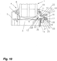
- a spreading force in the direction of the filling element 1 can be achieved even if the pressing leg 13 of the U-profile-like receiving area 11 is omitted and instead the spreading element 10 rests directly on the filling element 1 ( Fig.10 ).
- guide means 33 in particular guide grooves or guide projections, are formed on or in the support leg 12, on which the expansion element 10 is guided with corresponding guide means 33, in particular guide grooves or guide projections.
- the fixation of the expansion element 10 on the support leg 12 is again designed to be detachable.
- the expansion element 10 is thus guided along a support surface 34 of the support leg 12 which runs in a ramp-like manner towards the frame 3 in the direction of the filling element 1 and is spaced apart from the filling element 1.
- a design of the glass holder 2 without support feet 20 for fastening the glass holder 2 to frames 3 or frame profiles is shown on which, for example, no groove 21 is provided.
- Fig.6 a further embodiment of the glass holder 2 is shown, wherein the expansion element 10 is connected to the base body 16 via an elastic or flexible connection 38, in particular a tab.
- the flexible connection 38 ensures a one-piece arrangement of the expansion element 10 on the base body 16 and by tilting or pivoting the expansion element 10 into the receiving area 11 and fastening the expansion element 10, the pressure leg 13 is moved in the direction of the filling element 1, wherein the flexible connection 38 is now not separated from the base body 16 during assembly.
- the elastic, flexible connection 38 is fastened in the upper area of the support leg, whereby such a fastening can equally take place on the pressure leg or in the receiving area 11, in particular on the base 15.
- the attachment to the base 15 in the receiving area 11 can be carried out, for example, in such a way that the expansion element 10 is already held under a certain pre-tension in the receiving area 11, whereby the insertion of the expansion element 10 is eliminated during assembly and a predetermined positioning is made possible via the leg position of the expansion element 10 and the pressure legs 13 and support legs 12 delimiting the receiving area.
- the flexible Connection 38 is preferably attached to the top of the base 15 in the receiving area 11 on the one hand and to the underside of the expansion element 10.
- the pre-tension can be reduced or released by slightly pulling or lifting the expansion element 10 out of the receiving area 11 and the glass holder 2 can then be positioned in the groove 21, whereby when the expansion element is released, the glass holder 2 again assumes its pre-tension position and the filling element 1 is thus held in its position by the pre-tension even before it is fastened by means of the fastening means 14 or the screw.
- Fig.7 shows a design of the glass holder 2 in two separate components, namely the base body 16 and a separate expansion element 10.
- a structure serves, for example, to provide greater flexibility in delivery and assembly.
- expansion elements 10 of different sizes into the base body 16 or its receiving area 11 in order to preferably control the pivoting range, for example when mounting on special shapes of frame 3.
- FIGs. 8 and 9 another embodiment of the glass holder 2 is shown with a substantially triangular or V-shaped receiving area 11 and a corresponding spreading element 10.
- the base 15 is shown shorter for illustration purposes than, for example, in Fig. 2 to 4 , especially since 18 different dimensions are possible depending on the frame 3 and/or cladding profile.
- Fig.8 represents the original position in which the expansion element 10 is fastened via a predetermined breaking point 35 in the receiving area 11, in particular in the upper area of the support leg 12 and/or pressure leg 13.
- Fig.9 shows the preferred end position of the expansion element 10 and the pressing leg 13 pivoted in the direction of the filling element 1.
- the fastening means 14 is preferably designed as a thread, in particular as a screw, wherein the fastening means 14 is aligned essentially parallel to the support surface 34 in order to achieve the smoothest possible sliding along the support leg 12.
- the angles between the pressing leg 13 and the support leg 12 as well as the insertion leg 28 of the expansion element 10 - as shown - are selected so that the The pressing leg 13 is pivoted towards the filling element 1 and the filling element 1 is held and fixed via the pressing surface 6.
- the fastening or screwing direction and the different dimensional stability, in particular the stronger design of the support leg 12 in relation to the pressing leg 13, ensure reliable pivoting in the desired direction, with the expansion element 10 supporting and fixing the pressing leg in its position.
- the contact surface 6, on which a protective/sealing layer 9 (not shown) is preferably applied is aligned parallel to the filling element 1, there is still a free space 36 in the receiving area 11 for later readjustment and the expansion element 10 closes on the upper side flush with the receiving area or with the support and/or pressing legs 12, 13.
- Fig.10 shows a variant in which the pressing leg 13 is formed directly by the expansion element 10.
- the expansion element 10 is guided along the support leg 12 or the support surface 34 of the support leg 12.
- the force-applying surfaces and means run at approximately the same angle.
- Fig.10 visible - preferably the support surface 34 arranged on the base body 16 as well as the insertion leg 28 of the expansion element 10 and the thread-like fastening means 14 in particular essentially enclose the same angle to the filling element 1.
- a displacement in the direction of the filling element 1 and a contact pressure via the contact surface 6 is achieved.
- a free space 36 preferably remains between the expansion element 10 and the base 15 for possible readjustment or readjustment.
- guide means 33 can be formed on or in the support leg 12 and correspondingly on or in the expansion element 10 and/or the expansion element 10 can be positioned in the initial position via a predetermined breaking point 35 (not shown) on the base body 16.
- the expansion element 10 is connected via a rotatable or pivotable fixation, for example also a flexible connection 38 (as in Fig.6 ), is connected to the base body 16 at the top right corner, the sliding of the expansion element 10 along the support surface 34 and thus also the previously described identical angular arrangement is eliminated, since in this case the screw can also be screwed into the frame 3, for example, normal to the frame 3 or parallel to the filling element 1.
- the arrangement of guide means 33 can therefore also be omitted and it is also sufficient if, after the expansion element 10 has been pivoted into the receiving area 11, only a portion of the insertion legs 28 comes to rest on the support surface 34.
- the assembly is carried out in such a way that the expansion element 10 is pivoted into the receiving area 11 and then screwed on, whereby the fact that the expansion element 10 is larger in cross section than the receiving area 11 means that a contact pressure is achieved via the contact surface 6 on the filling element 1.
- a readjustment can be achieved by further fixing or screwing on the fastening means.
- the glass holder 2 is preferably made of plastic, in particular an injection-molded part, so that a one-piece design with a fixed expansion element 10 is advantageous.
- plastic in particular an injection-molded part
- other materials can be used or that, in a two-part design, different materials are used, for example a base body 16 made of plastic and an expansion element 10 made of metal.
- the glass holder 2 according to the invention in particular the expansion element 10, is always completely screwed in so that the maximum contact pressure is achieved.
- a glass holder 2 In order to ensure the static In order to meet these requirements, a glass holder 2 must be mounted every 20 to 25 cm, which requires easy handling of the glass holder 2 to ensure quick installation.
- the glass holder 2 it is also possible with the glass holder 2 according to the invention to dismantle and reassemble the cladding profile 18, in particular a glass strip, without causing any damage, as is necessary, for example, when replacing glass.
- the advantage here is that a consistent surface color is maintained, particularly with cladding profiles 18 or glass strips made of wood.
- the glass strip is attached without pressure when the glass holder 2 is used.
- the glass holder 2 takes on the static requirements, in particular the generation of the contact pressure, so that the cladding profile 18, in particular the glass strip, only provides the optical finish, which can simply be plugged onto or removed from the plug-in extensions 17.
- the cladding profile 18 can also be manufactured in different variants.
- the glass holder 2 according to the invention (“preferably with the product name of the applicant G-Fix 02") has significant advantages over the prior art, in particular the applicant's own application WO 2015/143462 A1 the first development stage "G-Fix or G-Fix 01". Thanks to the support foot 20, which goes into the groove 21, the glass holder 2 stays in the groove 21 by itself after it has been inserted. Both hands of the fitter are now free for the fastening means 14, in particular the screw, and the cordless screwdriver. The horizontal position of the glass holder 2 is also fixed. This ensures a constant distance to the inner edge of the frame, i.e. to the frame 3, and the glass strip, in particular the cladding profile 18, can then be easily and perfectly flush mounted with the frame 3. This avoids a wavy-mounted cladding profile 18, in particular the glass strip, which is often the cause of complaints.
- the glass holder 2 presses or presses the filling element 1, in particular the glass pane, outwards against the outer shell 4, in particular against the external outer seal, in particular the silicone foam seal, so that the outer seal can absorb the tolerances of the filling element 1 and seal against wind pressure and rain, so that no water can penetrate between the filling element 1 and the outer seal, ie that when the glass holder 2 is pressed against the Contact pressure is transferred via the filling element 1 to the outer seal so that it is deformed in such a way that a secure fit and seal on the filling element 1 is guaranteed, whereby a considerable contact pressure must be generated in order to be able to accommodate the tolerances of the filling element 1 of up to +/- 1.2mm and to be able to counteract the wind forces acting on it.
- the seal arranged on the inside in turn serves to ensure that no water can penetrate when cleaning the filling element 1, although the requirements are not as high on the inside as no wind pressure can occur here
Landscapes
- Engineering & Computer Science (AREA)
- Civil Engineering (AREA)
- Structural Engineering (AREA)
- Securing Of Glass Panes Or The Like (AREA)
Claims (11)
- Procédé pour le positionnement et/ou le maintien d'un élément de remplissage (1) ou d'une structure plate dans un cadre (3) de fenêtres, portes et dispositifs apparentés, la fixation s'effectuant à l'aide d'un support à verre (2), l'élément de remplissage (1) étant placé sur une coque extérieure (4) et monté ensuite sur le côté opposé de l'élément de remplissage (1) du support à verre (2) pour la fixation au cadre (3), un élément d'écartement (10) étant fixé par le biais d'un point de rupture programmé (35) ou d'une liaison élastique ou flexible (38), notamment une languette, à un corps principal (16) du support à verre (2), l'élément d'écartement (10) étant installé dans une zone de réception (11) entre une branche d'appui (12) et une branche de pression (13) et fixé par un élément de fixation (14), la branche d'appui (12) et la branche de pression (13) formant, l'une par rapport à l'autre, un angle (29) compris entre 1° et 65° lorsque le support à verre (2) est démonté, cet angle (29) augmentant lors de la mise en place de l'élément d'écartement (10), une force de serrage étant exercée et réglée par le pivotement de la branche de pression (13) en direction de l'élément de remplissage (1) en raison du déplacement de l'élément d'écartement (10) en direction d'une base (15) du support à verre (2) ou en direction du cadre (3).
- Procédé selon la revendication 1, caractérisé en ce que l'élément d'écartement (10) n'est pas vissé complètement dans la zone de réception (11), c.-à-d. jusqu'à la base (15), afin qu'un espace libre (36) se forme à l'état monté entre la base (15) et l'élément d'écartement (10) pour la fixation ultérieure en cas d'apparition d'un retrait.
- Procédé selon l'une des revendications précédentes 1 à 2, caractérisé en ce que la zone de réception (11) est formée avec une coupe transversale plus petite ou plus étroite que l'élément d'écartement (10).
- Procédé selon l'une des revendications précédentes 1 à 3, caractérisé en ce que la branche d'appui (12) et/ou une branche d'insertion (28) de l'élément d'écartement (10) reposant sur la branche d'appui (12) en position de montage est réalisée sous forme d'angle par rapport à la normale (31) sur la base (15).
- Procédé selon l'une des revendications précédentes 1 à 4, caractérisé en ce qu'une fixation plus ferme de l'élément de fixation (14) augmente la pression de serrage exercée sur l'élément de remplissage (1), et qu'un desserrage progressif de l'élément de fixation (14) permet de diminuer la pression de serrage.
- Procédé selon l'une des revendications précédentes 1 à 5, caractérisé en ce que, dans sa forme de section transversale, l'élément d'écartement (10) rétrécit au moins d'un côté, notamment sous forme de trapèze ou de coin.
- Support à verre (2) pour la réalisation du procédé selon l'une des revendications 1 à 6, comprenant au moins un corps principal (16) avec une surface de serrage (6) et un élément d'écartement (10), l'élément d'écartement (10) étant fixé par le biais d'un point de rupture programmé (35) ou d'une liaison élastique ou flexible (38), notamment une languette, à un corps principal (16), le support à verre (2) étant pourvu d'une branche d'appui (12) et d'une branche de pression (13), dotées d'une surface de serrage (6), en vue de la formation d'une zone de réception (11) pour l'élément d'écartement (10), caractérisé en ce que la branche d'appui (12) et la branche de pression (13) forment, l'une par rapport à l'autre, un angle (29) compris entre 1° et 65° lorsque le support à verre (2) est démonté, cet angle (29) augmentant lors de la mise en place de l'élément d'écartement (10).
- Support à verre (2) selon la revendication 7, caractérisé en ce que l'élément d'écartement (10) est fixé de manière amovible ou via un point de rupture programmé (35) à la branche d'appui (12) et/ou à la branche de pression (13).
- Support à verre (2) selon la revendication 7 ou 8, caractérisé en ce que la branche d'appui (12) est moins indéformable que la branche de pression (13).
- Support à verre (2) selon les revendications 7 à 9, caractérisé en ce que l'élément de fixation (14) est formé pour le réglage variable de la distance ou de la hauteur entre l'élément d'écartement (10) et le corps principal (16), notamment de la base (15), du support à verre (2), notamment en tant qu'élément à visser.
- Support à verre (2) selon l'une des revendications 7 à 10, caractérisé en ce qu'un pied d'appui (20) est installé sur le corps principal (16) en vue de l'insertion et du positionnement par rapport à l'élément de remplissage (1) dans une rainure (21).
Priority Applications (1)
| Application Number | Priority Date | Filing Date | Title |
|---|---|---|---|
| HRP20241386TT HRP20241386T1 (hr) | 2016-06-22 | 2017-06-08 | Držač za čaše i način njegovog sastavljanja |
Applications Claiming Priority (1)
| Application Number | Priority Date | Filing Date | Title |
|---|---|---|---|
| ATA309/2016A AT518808B1 (de) | 2016-06-22 | 2016-06-22 | Glashalter und Verfahren zur Montage hierfür |
Publications (3)
| Publication Number | Publication Date |
|---|---|
| EP3260644A1 EP3260644A1 (fr) | 2017-12-27 |
| EP3260644C0 EP3260644C0 (fr) | 2024-08-28 |
| EP3260644B1 true EP3260644B1 (fr) | 2024-08-28 |
Family
ID=59034421
Family Applications (1)
| Application Number | Title | Priority Date | Filing Date |
|---|---|---|---|
| EP17000976.5A Active EP3260644B1 (fr) | 2016-06-22 | 2017-06-08 | Porte-verre et son procédé de montage |
Country Status (5)
| Country | Link |
|---|---|
| EP (1) | EP3260644B1 (fr) |
| AT (1) | AT518808B1 (fr) |
| HR (1) | HRP20241386T1 (fr) |
| HU (1) | HUE069603T2 (fr) |
| PL (1) | PL3260644T3 (fr) |
Families Citing this family (6)
| Publication number | Priority date | Publication date | Assignee | Title |
|---|---|---|---|---|
| CN108301736B (zh) * | 2018-01-30 | 2023-07-28 | 陈莹 | 门窗玻璃压线框及门窗装置 |
| DE102018006913A1 (de) * | 2018-08-28 | 2020-03-05 | Pablo Bangratz | Tragprofil mit Stellelement |
| GB2609431B (en) * | 2021-07-30 | 2026-04-08 | Polar N E Ltd | Tamper resistant door |
| DE102022124992A1 (de) | 2022-09-28 | 2024-03-28 | Döpfner Betriebs GmbH & Co. KG | Rahmen zum Einfassen mindestens einer Scheibe und Vorrichtung umfassend den Rahmen und eine Zarge |
| CA3221824A1 (fr) * | 2022-12-02 | 2024-06-02 | Andersen Corporation | Dispositif d~autoserrage pour une unite de fenestration |
| DE102024104771A1 (de) * | 2024-02-21 | 2025-08-21 | Gutmann Bausysteme Gmbh | Glashalter, Rahmenkonstruktion sowie Verfahren zur Montage eines Glashalters |
Family Cites Families (5)
| Publication number | Priority date | Publication date | Assignee | Title |
|---|---|---|---|---|
| FR1521097A (fr) * | 1966-04-27 | 1968-04-12 | Eltreva Ag | Dispositif de vitrage à sec pour fenêtres et portes |
| US4825609A (en) * | 1988-08-26 | 1989-05-02 | The Bf Goodrich Company | Window molding |
| US8181405B2 (en) * | 2007-08-02 | 2012-05-22 | R&B Wagner, Inc. | Partition mounting system and clamp assembly for mounting partition |
| AT515424B1 (de) * | 2014-03-24 | 2015-09-15 | Goll Jürgen | Verfahren zum Befestigen oder Fixieren von Glasscheiben |
| WO2015145477A1 (fr) * | 2014-03-25 | 2015-10-01 | Ind.I.A. S.P.A. | Dispositif de verrouillage et de régulation pour panneaux et plaques |
-
2016
- 2016-06-22 AT ATA309/2016A patent/AT518808B1/de active
-
2017
- 2017-06-08 PL PL17000976.5T patent/PL3260644T3/pl unknown
- 2017-06-08 HR HRP20241386TT patent/HRP20241386T1/hr unknown
- 2017-06-08 EP EP17000976.5A patent/EP3260644B1/fr active Active
- 2017-06-08 HU HUE17000976A patent/HUE069603T2/hu unknown
Also Published As
| Publication number | Publication date |
|---|---|
| EP3260644C0 (fr) | 2024-08-28 |
| AT518808A1 (de) | 2018-01-15 |
| PL3260644T3 (pl) | 2024-12-16 |
| HRP20241386T1 (hr) | 2025-01-31 |
| AT518808B1 (de) | 2018-10-15 |
| HUE069603T2 (hu) | 2025-04-28 |
| EP3260644A1 (fr) | 2017-12-27 |
Similar Documents
| Publication | Publication Date | Title |
|---|---|---|
| EP3260644B1 (fr) | Porte-verre et son procédé de montage | |
| EP0341269A1 (fr) | Profile de recouvrement pour vitrages ou elements de remplissage de facade | |
| CH699782A2 (de) | Rahmenanschlussteil zur Befestigung an einem Rahmen. | |
| EP3199738B1 (fr) | Système de retenue de rambarde en verre et partie de renfort destinée à être utilisée dans un tel système | |
| WO2010063297A1 (fr) | Système de retenue pour vitres isolantes | |
| EP3477012B1 (fr) | Dispositif de retenue destiné à fixer un panneau de parapet ou de garde-corps | |
| EP3715575A1 (fr) | Cadre pour une fenêtre ou une porte, procédé de montage du cadre | |
| DE202015106983U1 (de) | System zur schraubenlosen Fixierung einer Glasscheibe | |
| DE2451813A1 (de) | Zargenbefestigungseinrichtung | |
| EP0446776B1 (fr) | Joint d'étanchéité profilé | |
| DE19516464A1 (de) | Bausatz zur Halterung einer aus Platten, insbesondere Glasplatten oder dergleichen zusammensetzbaren Fassade oder Dacheindeckung | |
| EP0702114A1 (fr) | Disposition de fixation pour bardage à façades | |
| EP3617419B1 (fr) | Profilé de support pourvu d'élément de réglage | |
| EP3995661B1 (fr) | Cadres de fenêtre ou de porte pourvus d'éléments coulissants et leur collage à la maçonnerie, ainsi que procédé de montage associé | |
| DE102018006913A1 (de) | Tragprofil mit Stellelement | |
| DE9414887U1 (de) | Vorrichtung zur Befestigung von Platten an Fassaden | |
| DE102013013074B4 (de) | Zargenkonstruktion zum Anschluss eines Fenster- oder Türrahmens an eine Gebäudewand | |
| EP0470603A1 (fr) | Dispositif d'étanchéité pour cadre de porte ou fenêtre | |
| DE102013110832B4 (de) | Vorrichtung zur Abdichtung von Tür- oder Fensterelementen | |
| EP2562325B1 (fr) | Système de raccordement d'isolation thermique | |
| DE202007019257U1 (de) | Glashalteleiste, Rahmenkonstruktion | |
| EP3064699B1 (fr) | Fenêtre ou porte et leur procédé de fabrication | |
| DE19733947C2 (de) | Verbindungseinheit für Rolladenkästen | |
| DE102013204944B4 (de) | Elastische Strangdichtung für Fenster, Türen oder dgl. | |
| DE102012104000B4 (de) | Halter zur Fixierung eines Isolationskörpers an einer Pfosten- und Riegelanordnung und eine solche Pfosten- und Riegelanordnung |
Legal Events
| Date | Code | Title | Description |
|---|---|---|---|
| REG | Reference to a national code |
Ref country code: HR Ref legal event code: TUEP Ref document number: P20241386T Country of ref document: HR |
|
| PUAI | Public reference made under article 153(3) epc to a published international application that has entered the european phase |
Free format text: ORIGINAL CODE: 0009012 |
|
| STAA | Information on the status of an ep patent application or granted ep patent |
Free format text: STATUS: THE APPLICATION HAS BEEN PUBLISHED |
|
| AK | Designated contracting states |
Kind code of ref document: A1 Designated state(s): AL AT BE BG CH CY CZ DE DK EE ES FI FR GB GR HR HU IE IS IT LI LT LU LV MC MK MT NL NO PL PT RO RS SE SI SK SM TR |
|
| AX | Request for extension of the european patent |
Extension state: BA ME |
|
| STAA | Information on the status of an ep patent application or granted ep patent |
Free format text: STATUS: REQUEST FOR EXAMINATION WAS MADE |
|
| 17P | Request for examination filed |
Effective date: 20180509 |
|
| STAA | Information on the status of an ep patent application or granted ep patent |
Free format text: STATUS: EXAMINATION IS IN PROGRESS |
|
| 17Q | First examination report despatched |
Effective date: 20200709 |
|
| GRAP | Despatch of communication of intention to grant a patent |
Free format text: ORIGINAL CODE: EPIDOSNIGR1 |
|
| STAA | Information on the status of an ep patent application or granted ep patent |
Free format text: STATUS: GRANT OF PATENT IS INTENDED |
|
| INTG | Intention to grant announced |
Effective date: 20240213 |
|
| GRAS | Grant fee paid |
Free format text: ORIGINAL CODE: EPIDOSNIGR3 |
|
| GRAA | (expected) grant |
Free format text: ORIGINAL CODE: 0009210 |
|
| STAA | Information on the status of an ep patent application or granted ep patent |
Free format text: STATUS: THE PATENT HAS BEEN GRANTED |
|
| AK | Designated contracting states |
Kind code of ref document: B1 Designated state(s): AL AT BE BG CH CY CZ DE DK EE ES FI FR GB GR HR HU IE IS IT LI LT LU LV MC MK MT NL NO PL PT RO RS SE SI SK SM TR |
|
| REG | Reference to a national code |
Ref country code: GB Ref legal event code: FG4D Free format text: NOT ENGLISH |
|
| REG | Reference to a national code |
Ref country code: CH Ref legal event code: EP |
|
| REG | Reference to a national code |
Ref country code: DE Ref legal event code: R096 Ref document number: 502017016379 Country of ref document: DE |
|
| REG | Reference to a national code |
Ref country code: IE Ref legal event code: FG4D Free format text: LANGUAGE OF EP DOCUMENT: GERMAN |
|
| U01 | Request for unitary effect filed |
Effective date: 20240903 |
|
| U07 | Unitary effect registered |
Designated state(s): AT BE BG DE DK EE FI FR IT LT LU LV MT NL PT RO SE SI Effective date: 20240916 |
|
| REG | Reference to a national code |
Ref country code: SK Ref legal event code: T3 Ref document number: E 45127 Country of ref document: SK |
|
| PG25 | Lapsed in a contracting state [announced via postgrant information from national office to epo] |
Ref country code: NO Free format text: LAPSE BECAUSE OF FAILURE TO SUBMIT A TRANSLATION OF THE DESCRIPTION OR TO PAY THE FEE WITHIN THE PRESCRIBED TIME-LIMIT Effective date: 20241128 |
|
| PG25 | Lapsed in a contracting state [announced via postgrant information from national office to epo] |
Ref country code: GR Free format text: LAPSE BECAUSE OF FAILURE TO SUBMIT A TRANSLATION OF THE DESCRIPTION OR TO PAY THE FEE WITHIN THE PRESCRIBED TIME-LIMIT Effective date: 20241129 |
|
| PG25 | Lapsed in a contracting state [announced via postgrant information from national office to epo] |
Ref country code: IS Free format text: LAPSE BECAUSE OF FAILURE TO SUBMIT A TRANSLATION OF THE DESCRIPTION OR TO PAY THE FEE WITHIN THE PRESCRIBED TIME-LIMIT Effective date: 20241228 |
|
| PG25 | Lapsed in a contracting state [announced via postgrant information from national office to epo] |
Ref country code: RS Free format text: LAPSE BECAUSE OF FAILURE TO SUBMIT A TRANSLATION OF THE DESCRIPTION OR TO PAY THE FEE WITHIN THE PRESCRIBED TIME-LIMIT Effective date: 20241128 Ref country code: ES Free format text: LAPSE BECAUSE OF FAILURE TO SUBMIT A TRANSLATION OF THE DESCRIPTION OR TO PAY THE FEE WITHIN THE PRESCRIBED TIME-LIMIT Effective date: 20240828 |
|
| PG25 | Lapsed in a contracting state [announced via postgrant information from national office to epo] |
Ref country code: RS Free format text: LAPSE BECAUSE OF FAILURE TO SUBMIT A TRANSLATION OF THE DESCRIPTION OR TO PAY THE FEE WITHIN THE PRESCRIBED TIME-LIMIT Effective date: 20241128 Ref country code: NO Free format text: LAPSE BECAUSE OF FAILURE TO SUBMIT A TRANSLATION OF THE DESCRIPTION OR TO PAY THE FEE WITHIN THE PRESCRIBED TIME-LIMIT Effective date: 20241128 Ref country code: IS Free format text: LAPSE BECAUSE OF FAILURE TO SUBMIT A TRANSLATION OF THE DESCRIPTION OR TO PAY THE FEE WITHIN THE PRESCRIBED TIME-LIMIT Effective date: 20241228 Ref country code: GR Free format text: LAPSE BECAUSE OF FAILURE TO SUBMIT A TRANSLATION OF THE DESCRIPTION OR TO PAY THE FEE WITHIN THE PRESCRIBED TIME-LIMIT Effective date: 20241129 Ref country code: ES Free format text: LAPSE BECAUSE OF FAILURE TO SUBMIT A TRANSLATION OF THE DESCRIPTION OR TO PAY THE FEE WITHIN THE PRESCRIBED TIME-LIMIT Effective date: 20240828 |
|
| REG | Reference to a national code |
Ref country code: HR Ref legal event code: T1PR Ref document number: P20241386 Country of ref document: HR |
|
| PG25 | Lapsed in a contracting state [announced via postgrant information from national office to epo] |
Ref country code: SM Free format text: LAPSE BECAUSE OF FAILURE TO SUBMIT A TRANSLATION OF THE DESCRIPTION OR TO PAY THE FEE WITHIN THE PRESCRIBED TIME-LIMIT Effective date: 20240828 |
|
| REG | Reference to a national code |
Ref country code: HU Ref legal event code: AG4A Ref document number: E069603 Country of ref document: HU |
|
| U20 | Renewal fee for the european patent with unitary effect paid |
Year of fee payment: 9 Effective date: 20250506 |
|
| PLBE | No opposition filed within time limit |
Free format text: ORIGINAL CODE: 0009261 |
|
| REG | Reference to a national code |
Ref country code: HR Ref legal event code: ODRP Ref document number: P20241386 Country of ref document: HR Payment date: 20250529 Year of fee payment: 9 |
|
| STAA | Information on the status of an ep patent application or granted ep patent |
Free format text: STATUS: NO OPPOSITION FILED WITHIN TIME LIMIT |
|
| PGFP | Annual fee paid to national office [announced via postgrant information from national office to epo] |
Ref country code: PL Payment date: 20250530 Year of fee payment: 9 |
|
| PGFP | Annual fee paid to national office [announced via postgrant information from national office to epo] |
Ref country code: HR Payment date: 20250529 Year of fee payment: 9 |
|
| PGFP | Annual fee paid to national office [announced via postgrant information from national office to epo] |
Ref country code: HU Payment date: 20250620 Year of fee payment: 9 |
|
| PGFP | Annual fee paid to national office [announced via postgrant information from national office to epo] |
Ref country code: SK Payment date: 20250603 Year of fee payment: 9 |
|
| PGFP | Annual fee paid to national office [announced via postgrant information from national office to epo] |
Ref country code: CZ Payment date: 20250603 Year of fee payment: 9 |
|
| 26N | No opposition filed |
Effective date: 20250530 |
|
| REG | Reference to a national code |
Ref country code: CH Ref legal event code: H13 Free format text: ST27 STATUS EVENT CODE: U-0-0-H10-H13 (AS PROVIDED BY THE NATIONAL OFFICE) Effective date: 20260127 |
|
| PG25 | Lapsed in a contracting state [announced via postgrant information from national office to epo] |
Ref country code: MC Free format text: LAPSE BECAUSE OF FAILURE TO SUBMIT A TRANSLATION OF THE DESCRIPTION OR TO PAY THE FEE WITHIN THE PRESCRIBED TIME-LIMIT Effective date: 20240828 |
|
| GBPC | Gb: european patent ceased through non-payment of renewal fee |
Effective date: 20250608 |
|
| PG25 | Lapsed in a contracting state [announced via postgrant information from national office to epo] |
Ref country code: GB Free format text: LAPSE BECAUSE OF NON-PAYMENT OF DUE FEES Effective date: 20250608 |
|
| PG25 | Lapsed in a contracting state [announced via postgrant information from national office to epo] |
Ref country code: IE Free format text: LAPSE BECAUSE OF NON-PAYMENT OF DUE FEES Effective date: 20250608 |
|
| PG25 | Lapsed in a contracting state [announced via postgrant information from national office to epo] |
Ref country code: CH Free format text: LAPSE BECAUSE OF NON-PAYMENT OF DUE FEES Effective date: 20250630 |