EP3260733B1 - Systeme d'isolation d'oscillations stationnaire actif - Google Patents
Systeme d'isolation d'oscillations stationnaire actif Download PDFInfo
- Publication number
- EP3260733B1 EP3260733B1 EP16175910.5A EP16175910A EP3260733B1 EP 3260733 B1 EP3260733 B1 EP 3260733B1 EP 16175910 A EP16175910 A EP 16175910A EP 3260733 B1 EP3260733 B1 EP 3260733B1
- Authority
- EP
- European Patent Office
- Prior art keywords
- piston
- pneumatic
- pneumatic actuator
- vibration isolation
- isolation system
- Prior art date
- Legal status (The legal status is an assumption and is not a legal conclusion. Google has not performed a legal analysis and makes no representation as to the accuracy of the status listed.)
- Active
Links
Images






Classifications
-
- F—MECHANICAL ENGINEERING; LIGHTING; HEATING; WEAPONS; BLASTING
- F16—ENGINEERING ELEMENTS AND UNITS; GENERAL MEASURES FOR PRODUCING AND MAINTAINING EFFECTIVE FUNCTIONING OF MACHINES OR INSTALLATIONS; THERMAL INSULATION IN GENERAL
- F16F—SPRINGS; SHOCK-ABSORBERS; MEANS FOR DAMPING VIBRATION
- F16F15/00—Suppression of vibrations in systems; Means or arrangements for avoiding or reducing out-of-balance forces, e.g. due to motion
- F16F15/02—Suppression of vibrations of non-rotating, e.g. reciprocating systems; Suppression of vibrations of rotating systems by use of members not moving with the rotating systems
- F16F15/023—Suppression of vibrations of non-rotating, e.g. reciprocating systems; Suppression of vibrations of rotating systems by use of members not moving with the rotating systems using fluid means
- F16F15/027—Suppression of vibrations of non-rotating, e.g. reciprocating systems; Suppression of vibrations of rotating systems by use of members not moving with the rotating systems using fluid means comprising control arrangements
- F16F15/0275—Control of stiffness
-
- F—MECHANICAL ENGINEERING; LIGHTING; HEATING; WEAPONS; BLASTING
- F16—ENGINEERING ELEMENTS AND UNITS; GENERAL MEASURES FOR PRODUCING AND MAINTAINING EFFECTIVE FUNCTIONING OF MACHINES OR INSTALLATIONS; THERMAL INSULATION IN GENERAL
- F16F—SPRINGS; SHOCK-ABSORBERS; MEANS FOR DAMPING VIBRATION
- F16F15/00—Suppression of vibrations in systems; Means or arrangements for avoiding or reducing out-of-balance forces, e.g. due to motion
- F16F15/02—Suppression of vibrations of non-rotating, e.g. reciprocating systems; Suppression of vibrations of rotating systems by use of members not moving with the rotating systems
- F16F15/023—Suppression of vibrations of non-rotating, e.g. reciprocating systems; Suppression of vibrations of rotating systems by use of members not moving with the rotating systems using fluid means
- F16F15/027—Suppression of vibrations of non-rotating, e.g. reciprocating systems; Suppression of vibrations of rotating systems by use of members not moving with the rotating systems using fluid means comprising control arrangements
-
- F—MECHANICAL ENGINEERING; LIGHTING; HEATING; WEAPONS; BLASTING
- F16—ENGINEERING ELEMENTS AND UNITS; GENERAL MEASURES FOR PRODUCING AND MAINTAINING EFFECTIVE FUNCTIONING OF MACHINES OR INSTALLATIONS; THERMAL INSULATION IN GENERAL
- F16F—SPRINGS; SHOCK-ABSORBERS; MEANS FOR DAMPING VIBRATION
- F16F15/00—Suppression of vibrations in systems; Means or arrangements for avoiding or reducing out-of-balance forces, e.g. due to motion
- F16F15/02—Suppression of vibrations of non-rotating, e.g. reciprocating systems; Suppression of vibrations of rotating systems by use of members not moving with the rotating systems
- F16F15/023—Suppression of vibrations of non-rotating, e.g. reciprocating systems; Suppression of vibrations of rotating systems by use of members not moving with the rotating systems using fluid means
- F16F15/0232—Suppression of vibrations of non-rotating, e.g. reciprocating systems; Suppression of vibrations of rotating systems by use of members not moving with the rotating systems using fluid means with at least one gas spring
-
- G—PHYSICS
- G03—PHOTOGRAPHY; CINEMATOGRAPHY; ANALOGOUS TECHNIQUES USING WAVES OTHER THAN OPTICAL WAVES; ELECTROGRAPHY; HOLOGRAPHY
- G03F—PHOTOMECHANICAL PRODUCTION OF TEXTURED OR PATTERNED SURFACES, e.g. FOR PRINTING, FOR PROCESSING OF SEMICONDUCTOR DEVICES; MATERIALS THEREFOR; ORIGINALS THEREFOR; APPARATUS SPECIALLY ADAPTED THEREFOR
- G03F7/00—Photomechanical, e.g. photolithographic, production of textured or patterned surfaces, e.g. printing surfaces; Materials therefor, e.g. comprising photoresists; Apparatus specially adapted therefor
- G03F7/70—Microphotolithographic exposure; Apparatus therefor
- G03F7/708—Construction of apparatus, e.g. environment aspects, hygiene aspects or materials
- G03F7/70858—Environment aspects, e.g. pressure of beam-path gas, temperature
- G03F7/709—Vibration, e.g. vibration detection, compensation, suppression or isolation
Definitions
- the invention relates to a stationary vibration isolation system with an insulator.
- the invention relates to a designed as a pneumatic spring insulator with an actuator for active vibration isolation.
- the invention relates to stationary, ie stationary, arranged vibration isolation systems on which lithography and / or metrology systems for the processing of semiconductor components are mounted vibration-isolated.
- Stationary vibration isolation systems as used in particular for accommodating lithography or metrology devices for processing semiconductors, usually consist of a table which is mounted on a plurality of insulators.
- the size of the semiconductor devices to be processed also increases the size of the systems used for this purpose.
- applied by the actuators reaction forces are always higher, which complicates the use of electrically driven actuators.
- several actuators operating according to the magnetic principle have to be connected in parallel in one effective direction. This is expensive and not possible due to the tight space in some applications.
- the use of magnetic actuators is further limited by their always existing heat dissipation.
- a mechanical vibration isolator with a coil spring is in the published patent application EP 2 759 763 A2 (Integrated Dynamics Engineering GmbH)
- the publication EP 2 998 611 A2 shows an insulator with an air spring whose characteristics are adaptable via an exchangeable leaf spring package and which has a bending pendulum to provide an insulating effect in the horizontal direction.
- the invention is based on the object to reduce the disadvantages of the prior art.
- a flexible isolator for an active vibration isolation system is to be provided, with which high compensation forces can be achieved with low heat dissipation.
- the invention relates to a stationary vibration isolation system with an insulator.
- the invention relates to a vibration isolation system on which machines for processing semiconductor devices, in particular lithography or metrology devices, are mounted vibration-isolated.
- Such a vibration isolation system usually comprises a plate, which is arranged vibration-insulated from the ground via at least three insulators.
- the insulator is effective in the horizontal and vertical directions, i. a decoupling from the ground is provided both in the horizontal and in the vertical direction.
- the insulator for this purpose comprises a spring which is effective at least in the vertical direction
- the spring is formed according to the invention as a pneumatic spring.
- the pneumatic spring is effective only in the vertical direction, whereas for decoupling in the horizontal direction, another component, in particular a bending pendulum, is provided.
- the insulator comprises at least one pneumatic actuator.
- the insulator is thus intended for use in an active vibration isolation system, in which by means of a pneumatic actuator compensation forces for the active reduction of vibrations can be generated.
- the actuator is preferably not the decoupling of the vibration-isolated mounted load from the ground, but solely to generate compensation forces to generate opposing forces.
- the actuator for generating compensation forces is designed as a pneumatic actuator. It has been found that even with a pneumatic actuator high counter forces can be generated. At the same time, the heat dissipation is considerably reduced compared to electrically operated actuators.
- the pneumatic actuator extends annularly around a piston of the pneumatic spring.
- the pneumatic actuator is such an integral part of the insulator. This allows a particularly compact design.
- the pneumatic actuator can be arranged in a working space of the pneumatic spring.
- a piston of the pneumatic actuator is guided over at least two spaced-apart leaf springs.
- a piston of a pneumatic spring of the insulator is axially guided via the at least two spaced-apart leaf springs.
- both the pneumatic actuator and the pneumatic spring are effective only in one spatial direction, preferably only in the vertical direction.
- spaced-apart leaf springs are provided, via which the pistons are respectively coupled to the base of the insulator, ie with the bottom-side part of the insulator, such that the two pistons only in to move in the axial direction.
- the pneumatic actuator is effective in two spatial directions.
- the piston divides the working space of the actuator into two pressure chambers.
- the piston can be displaced by introducing fluid into the respective pressure chamber in two opposite directions.
- the insulator comprises both an actuator acting in the horizontal direction and an actuator acting in the vertical direction.
- Both actuators are preferably designed as pneumatic actuators. Thus, compensation forces can be generated both in the vertical and in the horizontal direction.
- the active in the vertical direction pneumatic actuator preferably has an axis of action, which is located substantially on the axis of action of the spring, in particular the pneumatic spring.
- the pneumatic actuator comprises an annular working space in which a piston is arranged.
- the pneumatic actuator is so annular, which on the one hand makes it possible to pass a component of the insulator, such as the part of a spring, through the actuator.
- the pneumatic actuator comprises a piston, which is preferably spaced by a gap from the wall of the working space.
- the working space is divided according to an embodiment of the invention into two pressure chambers.
- two work spaces defined by the pressure chambers are present, which makes it possible in a simple manner to effectively design the pneumatic actuator in two opposite directions.
- the working space or the two pressure chambers are preferably closed by at least one membrane.
- the sealing of the working space is therefore not carried by the piston running in the working space, but by an elastic membrane. This allows a particularly low rigidity in the direction of action, since no components touch rubbing. At the same time the generation of vibrations due to mutually sliding components is avoided.
- the active vibration isolation system usually includes sensors, are detected by the vibrations of the soil and / or vibrations of the vibration-isolated mounted load. These sensors are connected to a control device, are controlled via the actuators to generate compensation forces.
- These compensating forces can both counteract oscillations that extend into the system at the bottom, and also reduce vibrations that are generated by parts of the load mounted in a vibration-isolated manner, such as machines with moving parts.
- a pressure sensor is integrated, the pressure within a Working space of the pneumatic actuator, in particular within a pressure chamber, measures.
- a pressure sensor can be achieved in a simple manner a proportionality.
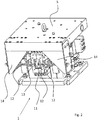
- Fig. 1 is a cutaway perspective view of an embodiment of an insulator 1 according to the invention.
- the insulator 1 comprises an upper part 5, which is formed in this embodiment as a plate and which is part of the load to be insulated in the installed state.
- the upper part 5 is mounted vibration-isolated with respect to the base 6, which is connected to the ground in the installed state.
- the insulator 1 comprises a pneumatic spring.
- the piston 2 is supported, thus providing a vibration isolation in the vertical direction.
- the working space 3 is closed by a membrane 45.
- the piston 2 is axially guided by two spaced-apart leaf spring assemblies 8, 9.
- the bending pendulum 4 is located in a recess 7 of the piston 2.
- the isolator 1 comprises the pneumatic actuator 10, which is effective in the vertical direction and can be generated via the compensation forces.
- the pneumatic actuator 10 is annular and is located in the working space 3 of the pneumatic spring.
- At least one further pneumatic actuator 11 is provided, which is located next to the housing 46 of the working space 3 of the pneumatic spring.
- Fig. 2 is a perspective view of the in Fig. 1 represented actuator.
- an extension 13 protrudes from the pneumatic actuator 11.
- the extension 13 is with a Piston connected or part of a piston, by means of which opposing forces are generated.
- the piston is connected via bending rods 12 with arms 14 of the upper part 5.
- the bending rods 12 are used for decoupling the actuator 11 transversely to its direction of action.
- the extension 13 to be seen here looks laterally out of the housing of the pneumatic actuator 11. Further extensions are arranged within the housing, wherein the bending rods are guided in this case through openings of the housing of the pneumatic actuator 11.
- Fig. 3 is a perspective view of the in Fig. 1 illustrated pneumatic actuator 10th
- the pneumatic actuator 10 is annular and consists of a housing 16 in which an axially movable piston 15 is arranged.
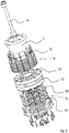
- Fig. 4 is an exploded view of the in Fig. 3 illustrated pneumatic actuator.
- the housing consists of three parts, namely the upper housing part 16a, the middle part 16b and the lower housing part 16c.
- a piston is arranged, which consists in this embodiment of a piston center part 17 on which the extensions 25a and 25b are mounted.
- the extensions 25a and 25b can be connected to the load to be insulated, whereas the housing (consisting of the parts 16a to 16c) is coupled to the base.
- the pneumatic actuator 10 shown here operates in two opposite directions.
- the piston or the piston middle part 17 divides the working space into two pressure chambers.
- the pressure chambers are each closed with a membrane 18a, 18b, so that in this embodiment, a pressure chamber between the upper housing part 16a and the diaphragm 18a and the other pressure chamber between the housing base 16c and the diaphragm 18b is located.
- the membranes 18a, 18b are connected to the piston or piston middle part 17.
- a clamping ring 19a, 19b is provided in each case.
- the clamping rings 19a and 19b are thus each in the pressure chamber.
- the clamping rings 19a and 19b are fastened with the screws 21a and 21b on the piston or on the piston center part 17 and fix a respective membrane 18a, 18b.
- a relative to the clamping rings 19a and 19b opposite clamping ring 22a, 22b fixes the membrane 18a, 18b respectively on the housing or on the upper housing part 16a and the lower housing part 16c.
- Upper housing part 16a and lower housing part 16c are connected in this embodiment with the screws 20a and 20b with the middle part 16b.
- screws 23a, 23b are screwed into the threaded sleeves 24 and thus connect the upper housing part 16a and the lower housing part 16c.
- the threaded sleeves 24 are guided by bores of the piston or the piston center part 17, which are so large that the threaded sleeves 24 in the piston have so much game that they do not rest against the holes of the piston.
- the membrane 18a and 18b serves at the same time to seal the upper housing part 16a and the lower housing part 16c relative to the central housing part 16b.
- pneumatic actuator 10 further also fluid feeds to supply compressed air to the work spaces.
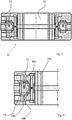
- Fig. 5 is a sectional view of the previously illustrated pneumatic actuator 10th
- the pneumatic actuator 10 has a central passage 27 through which, for example, components of the insulator can be passed.
- Fig. 6 is a detail view of the Fig. 5 .
- the piston 15 is spaced by a gap 28 from the adjacent housing wall.
- the pressure chambers 26a and 26b are closed by means of a membrane 18a, 18b.
- the working space formed by the pressure chambers 26a, 26b is quite small.
- a very small working space in particular a working space of less than 10 cm 3 , preferably less than 5 cm 3 , is sufficient, since the actuator does not serve as a pneumatic spring but only to generate opposing forces.
- the volume of the working space of the pneumatic actuator (sum of the volumes of the pressure chambers) is preferably at most 1/5, more preferably at most 1/10, of the volume of the working space of the pneumatic spring.
- Fig. 7 is a perspective view of the pneumatic actuator, wherein the upper housing part and the membrane, with which the upper working space is closed, are hidden.
- threaded sleeves 24 are connected via the upper housing part and lower housing part and which are arranged with play in holes 29 of the piston 15.
- Fig. 8 is another sectional view of the insulator.
- the piston 15 is connected to the piston 2.
- the axis of action of the pneumatic spring with the piston 2 and the axis of action of the pneumatic actuator 10 are so each other.
- both the piston 2 and the piston 15 of the pneumatic actuator is guided axially by the spaced apart leaf springs of the leaf spring assemblies.
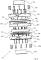
- Fig. 9 is an exploded perspective view of the components which are arranged in the assembled state in the working space of the pneumatic spring.
- both the leaf springs 31 of the upper leaf spring packet 9 and the leaf springs 30 of the lower leaf spring packet 8 consist of ring segments.
- the pneumatic actuator 10 can be mounted in a simple manner.
- the piston 15 is connected to both the piston 2 and the leaf spring assemblies 8 and 9.
- Fig. 10 shows the in Fig. 9 shown components in the assembled state.
- the pneumatic actuator 10 is an integral part of an inner part of the pneumatic spring comprising the piston 2, out of which the bending pendulum 4 protrudes, which is coupled to the load to be insulated.
- Fig. 11 is an exploded view of the in Fig. 1 shown further pneumatic actuator 11, which serves to generate horizontal compensation forces.
- the pneumatic actuator 11 comprises a housing with a housing upper part 33a and a housing lower part 33b, in which, in the assembled state, the piston 32 is inserted, which divides the working space into two halves.
- the upper housing part 33a is correspondingly formed and likewise comprises a pressure chamber closed with a membrane, so that the actuator 11 is also effective in two opposite directions.
- the piston 32 has three extensions 34a - 34c, on which bending rods can be attached (12 in FIG Fig. 2 ), via which the pneumatic actuator 11 is connected to the load to be isolated.
- the extension 34b is led out of the housing.
- the bending rods to be attached to the extensions 34a and 34c are guided through the bores 35 of the housing in the assembled state.
- Fig. 12 is a schematic representation of a vibration isolation system 40, in which the insulators 1 described above are installed.
- the vibration isolation system 40 comprises a plate 44 which is mounted on a plurality of isolators 1 vibration-isolated on the bottom 39.
- both a sensor 37 is provided, which detects vibrations of the soil, as well as a sensor 38, which detects vibrations of the load to be isolated.
- control device 41 which in turn controls pneumatic valves 42, 43 for controlling the pneumatic actuators 10, 11 integrated in the isolators 1.
- an insulator could be provided which generates high compensation forces in an active vibration isolation system with low heat dissipation.
Landscapes
- Engineering & Computer Science (AREA)
- General Engineering & Computer Science (AREA)
- Physics & Mathematics (AREA)
- Acoustics & Sound (AREA)
- Aviation & Aerospace Engineering (AREA)
- Mechanical Engineering (AREA)
- Vibration Prevention Devices (AREA)
- Springs (AREA)
Claims (10)
- Système actif fixe d'isolation des vibrations (40), comprenant au moins un isolateur (1), lequel agit dans les directions horizontale et verticale, dans lequel l'isolateur (1) comprend un actionneur pneumatique (11) agissant dans la direction horizontale et un actionneur pneumatique (10) agissant dans la direction verticale,
dans lequel les actionneurs pneumatiques (10, 11) agissent dans deux directions spatiales, et dans lequel des forces de compensation peuvent être produites aussi bien dans la direction verticale que dans la direction horizontale au moyen des actionneurs pneumatiques (10, 11) pour réduire activement les vibrations, caractérisé en ce que l'isolateur comprend en outre un ressort pneumatique qui agit au moins dans la direction verticale. - Système actif fixe d'isolation des vibrations (40) selon la revendication précédente, caractérisé en ce que l'actionneur pneumatique (10) agissant dans la direction verticale s'étend de manière annulaire autour d'un piston (2) du ressort pneumatique.
- Système actif fixe d'isolation des vibrations (40) selon l'une quelconque des revendications précédentes, caractérisé en ce que l'actionneur pneumatique (10) agissant dans la direction verticale est agencé dans une chambre de travail (3) du ressort pneumatique.
- Système actif fixe d'isolation des vibrations (40) selon l'une quelconque des revendications précédentes, caractérisé en ce qu'un piston (15) de l'actionneur pneumatique (10) agissant dans la direction verticale est guidé axialement par l'intermédiaire d'au moins deux ressorts à lames espacés l'un de l'autre.
- Système actif fixe d'isolation des vibrations (40) selon la revendication précédente, caractérisé en ce qu'un piston (2) du ressort pneumatique est lui aussi guidé axialement par l'intermédiaire des au moins deux ressorts à lames espacés l'un de l'autre.
- Système actif fixe d'isolation des vibrations (40) selon l'une quelconque des revendications précédentes, dans lequel l'actionneur pneumatique (10) comprend une chambre de travail annulaire dans laquelle est agencé un piston (15).
- Système actif fixe d'isolation des vibrations (40) selon la revendication précédente, caractérisé en ce que le piston (15) est espacé de la paroi de la chambre de travail par une fente (28).
- Système actif fixe d'isolation des vibrations (40) selon la revendication 6 ou 7, caractérisé en ce que le piston (15) divise la chambre de travail en deux chambres de pression (26a, 26b).
- Système actif fixe d'isolation des vibrations (40) selon la revendication 7 ou 8, caractérisé en ce que la chambre de travail est fermée par au moins une membrane (18a, 18b).
- Système actif fixe d'isolation des vibrations (40) selon l'une quelconque des revendications précédentes, comprenant, pour la commande de l'actionneur pneumatique (10), une boucle d'asservissement dans laquelle est inséré un capteur de pression, qui mesure la pression à l'intérieur d'une chambre de travail de l'actionneur pneumatique, ou un capteur de force, qui mesure la pression exercée par l'actionneur pneumatique.
Priority Applications (4)
| Application Number | Priority Date | Filing Date | Title |
|---|---|---|---|
| EP16175910.5A EP3260733B1 (fr) | 2016-06-23 | 2016-06-23 | Systeme d'isolation d'oscillations stationnaire actif |
| US15/619,088 US10634210B2 (en) | 2016-06-23 | 2017-06-09 | Isolator for a stationary vibration isolation system |
| KR1020170075033A KR102462325B1 (ko) | 2016-06-23 | 2017-06-14 | 고정식 방진 시스템용 아이솔레이터 |
| JP2017121476A JP7058477B2 (ja) | 2016-06-23 | 2017-06-21 | 固定防振システムのための防振装置 |
Applications Claiming Priority (1)
| Application Number | Priority Date | Filing Date | Title |
|---|---|---|---|
| EP16175910.5A EP3260733B1 (fr) | 2016-06-23 | 2016-06-23 | Systeme d'isolation d'oscillations stationnaire actif |
Publications (2)
| Publication Number | Publication Date |
|---|---|
| EP3260733A1 EP3260733A1 (fr) | 2017-12-27 |
| EP3260733B1 true EP3260733B1 (fr) | 2019-08-07 |
Family
ID=56411391
Family Applications (1)
| Application Number | Title | Priority Date | Filing Date |
|---|---|---|---|
| EP16175910.5A Active EP3260733B1 (fr) | 2016-06-23 | 2016-06-23 | Systeme d'isolation d'oscillations stationnaire actif |
Country Status (4)
| Country | Link |
|---|---|
| US (1) | US10634210B2 (fr) |
| EP (1) | EP3260733B1 (fr) |
| JP (1) | JP7058477B2 (fr) |
| KR (1) | KR102462325B1 (fr) |
Families Citing this family (4)
| Publication number | Priority date | Publication date | Assignee | Title |
|---|---|---|---|---|
| EP3181944B1 (fr) | 2015-12-16 | 2023-04-26 | Integrated Dynamics Engineering GmbH | Isolateur de vibrations doté d'un ressort pneumatique vertical |
| EP3260732B1 (fr) * | 2016-06-23 | 2019-03-27 | Integrated Dynamics Engineering GmbH | Actionneur pneumatique et procede de fonctionnement d'un systeme actif d'isolation d'oscillations |
| JP6969975B2 (ja) * | 2017-10-24 | 2021-11-24 | 株式会社三共 | 遊技機 |
| US10991544B2 (en) * | 2019-05-29 | 2021-04-27 | ICT Integrated Circuit Testing Gesellschaft für Halbleiterprüftechnik mbH | Charged particle beam device, objective lens module, electrode device, and method of inspecting a specimen |
Citations (1)
| Publication number | Priority date | Publication date | Assignee | Title |
|---|---|---|---|---|
| US20010040324A1 (en) * | 1998-04-08 | 2001-11-15 | Fitzpatrick Cella Harper & Scinto | Anti-vibration apparatus, exposure apparatus using the same, device manufacturing method, and anti-vibration method |
Family Cites Families (38)
| Publication number | Priority date | Publication date | Assignee | Title |
|---|---|---|---|---|
| US3889936A (en) * | 1974-04-12 | 1975-06-17 | Wright Barry Corp | Combined air mounts |
| SU612087A1 (ru) | 1975-10-31 | 1978-06-25 | Научно-Производственное Объединение "Автоматгормаш" | Пневматический исполнительный механизм |
| DE69014750T2 (de) * | 1989-07-24 | 1995-07-06 | Tokkyo Kiki K K | Verfahren zur Positions- und Vibrationssteuerung und eine aktive Vibrationssteuervorrichtung. |
| IT1231308B (it) | 1989-07-27 | 1991-11-28 | Tetra Dev Co | Unita' a pistone con membrana a rotolamento |
| JPH0455577A (ja) * | 1990-06-22 | 1992-02-24 | Mitsubishi Electric Corp | 構造物の制振装置 |
| US5111735A (en) * | 1990-10-30 | 1992-05-12 | Beloit Corporation | Air spring with quick release valve |
| JPH04244628A (ja) * | 1991-01-28 | 1992-09-01 | Kurashiki Kako Co Ltd | 空気ばねの制御装置 |
| DE4133878C2 (de) * | 1991-10-12 | 1995-04-13 | Continental Ag | Luftfeder mit einem Schlauchrollbalg aus elastomerem Werkstoff |
| DE4241997C1 (de) | 1992-12-12 | 1994-05-26 | Daimler Benz Ag | Pneumatisch steuerbarer Stellantrieb |
| JP3661877B2 (ja) * | 1993-03-02 | 2005-06-22 | 株式会社日立製作所 | 車両用制振装置 |
| DE4324595C1 (de) * | 1993-07-22 | 1994-12-15 | Escher Wyss Gmbh | Schüttelbock |
| JP3777016B2 (ja) * | 1997-03-31 | 2006-05-24 | 藤倉ゴム工業株式会社 | 空気圧シリンダ装置 |
| JP2000220690A (ja) * | 1999-02-01 | 2000-08-08 | Canon Inc | 能動的除振装置、露光装置およびデバイス製造方法 |
| US7095482B2 (en) | 2001-03-27 | 2006-08-22 | Nikon Corporation | Multiple system vibration isolator |
| JP3799244B2 (ja) * | 2001-06-13 | 2006-07-19 | 倉敷化工株式会社 | 気体ばね式除振装置 |
| US6746005B1 (en) * | 2001-10-04 | 2004-06-08 | The United States Of America As Represented By The Secretary Of The Navy | Constant natural frequency passive-active mount |
| JP2004131180A (ja) | 2002-07-09 | 2004-04-30 | Imi Cornelius (Uk) Ltd | 飲料の注出における改良または飲料の注出に関連する改良 |
| JP2005114083A (ja) * | 2003-10-09 | 2005-04-28 | Ebara Corp | 真空チャンバの除振システム |
| JP4463573B2 (ja) | 2004-01-22 | 2010-05-19 | 藤倉ゴム工業株式会社 | 除振装置 |
| JP2005282696A (ja) * | 2004-03-29 | 2005-10-13 | Canon Inc | 除振マウント装置、露光装置及びデバイス製造方法 |
| JP2006083883A (ja) * | 2004-09-14 | 2006-03-30 | Fujikura Rubber Ltd | 除振台装置 |
| US7552620B2 (en) | 2006-09-07 | 2009-06-30 | 3M Innovative Properties Company | Fluid permeation testing method employing mass spectrometry |
| US20090283942A1 (en) * | 2006-09-26 | 2009-11-19 | The Yokohama Rubber Co., Ltd. | Vibration transmission damping apparatus |
| JP4940472B2 (ja) * | 2007-06-08 | 2012-05-30 | 倉敷化工株式会社 | アクティブ除振装置及び制振装置 |
| DE102007059631B4 (de) | 2007-12-10 | 2009-09-17 | Integrated Dynamics Engineering Gmbh | Schwingungsisolator zur Verwendung im Vakuum |
| JP2009188053A (ja) * | 2008-02-04 | 2009-08-20 | Canon Inc | 露光装置およびデバイス製造方法 |
| JP5064316B2 (ja) * | 2008-07-01 | 2012-10-31 | 特許機器株式会社 | 除振装置 |
| JP5439082B2 (ja) * | 2009-07-30 | 2014-03-12 | 倉敷化工株式会社 | マスダンパ |
| JP5015309B2 (ja) * | 2009-11-24 | 2012-08-29 | ヤマハ発動機株式会社 | 車両用油圧式緩衝器 |
| AU2011338574B2 (en) * | 2010-12-07 | 2015-07-09 | General Compression, Inc. | Compressor and/or expander device with rolling piston seal |
| US9039217B2 (en) | 2011-09-21 | 2015-05-26 | Lg Innotek Co., Ltd. | Lighting device |
| FR2993943B1 (fr) | 2012-07-24 | 2017-04-28 | Peugeot Citroen Automobiles Sa | Actionneur pneumatique, en particulier pour la regulation de l'ouverture de la soupape de decharge d'un turbocompresseur |
| CN103047346B (zh) * | 2012-12-19 | 2014-06-11 | 哈尔滨工业大学 | 滚动关节轴承角度解耦的磁浮零刚度隔振器与隔振系统 |
| EP2759735B1 (fr) * | 2013-01-29 | 2016-06-15 | Integrated Dynamics Engineering GmbH | Système d'isolation d'oscillations stationnaire ainsi que le procédé destiné à régler un système d'isolation d'oscillations |
| EP2759736B1 (fr) | 2013-01-29 | 2015-09-16 | Integrated Dynamics Engineering GmbH | Isolateur de vibrations comprenant un ressort cylindrique |
| EP2998611B1 (fr) | 2014-09-18 | 2019-07-24 | Integrated Dynamics Engineering GmbH | Isolateur de vibrations doté de ressort pneumatique |
| EP3181944B1 (fr) | 2015-12-16 | 2023-04-26 | Integrated Dynamics Engineering GmbH | Isolateur de vibrations doté d'un ressort pneumatique vertical |
| EP3260732B1 (fr) * | 2016-06-23 | 2019-03-27 | Integrated Dynamics Engineering GmbH | Actionneur pneumatique et procede de fonctionnement d'un systeme actif d'isolation d'oscillations |
-
2016
- 2016-06-23 EP EP16175910.5A patent/EP3260733B1/fr active Active
-
2017
- 2017-06-09 US US15/619,088 patent/US10634210B2/en active Active
- 2017-06-14 KR KR1020170075033A patent/KR102462325B1/ko active Active
- 2017-06-21 JP JP2017121476A patent/JP7058477B2/ja active Active
Patent Citations (1)
| Publication number | Priority date | Publication date | Assignee | Title |
|---|---|---|---|---|
| US20010040324A1 (en) * | 1998-04-08 | 2001-11-15 | Fitzpatrick Cella Harper & Scinto | Anti-vibration apparatus, exposure apparatus using the same, device manufacturing method, and anti-vibration method |
Also Published As
| Publication number | Publication date |
|---|---|
| KR102462325B1 (ko) | 2022-11-02 |
| JP2017227331A (ja) | 2017-12-28 |
| US20170370441A1 (en) | 2017-12-28 |
| KR20180000679A (ko) | 2018-01-03 |
| EP3260733A1 (fr) | 2017-12-27 |
| JP7058477B2 (ja) | 2022-04-22 |
| US10634210B2 (en) | 2020-04-28 |
Similar Documents
| Publication | Publication Date | Title |
|---|---|---|
| EP3260732B1 (fr) | Actionneur pneumatique et procede de fonctionnement d'un systeme actif d'isolation d'oscillations | |
| EP3181944B1 (fr) | Isolateur de vibrations doté d'un ressort pneumatique vertical | |
| EP3260733B1 (fr) | Systeme d'isolation d'oscillations stationnaire actif | |
| DE102005053244B4 (de) | Aktive Schwingungsdämpfungsvorrichtung | |
| EP2759735B1 (fr) | Système d'isolation d'oscillations stationnaire ainsi que le procédé destiné à régler un système d'isolation d'oscillations | |
| EP2998611B1 (fr) | Isolateur de vibrations doté de ressort pneumatique | |
| DE102014208083A1 (de) | Dämpfer für ein Fahrzeug | |
| WO2009059658A1 (fr) | Vanne de distribution à commande pilote, destinée en particulier à commander un vérin de commande d'une turbomachine | |
| DE102016218375A1 (de) | Dämpfventil für einen Schwingungsdämpfer | |
| EP3207436B1 (fr) | Servovalve à autorégulation | |
| DE60014351T2 (de) | Systeme und verfahren für den passiven druckausgleich für akustische sensoren | |
| DE3831928A1 (de) | Vorrichtung zur stabilisierung von achsen bzw. wellen | |
| EP3158220A1 (fr) | Palier hydraulique et véhicule à moteur équipé d'un tel palier hydraulique | |
| EP3221612B1 (fr) | Palier hydraulique et véhicule à moteur équipé d'un tel palier hydraulique | |
| EP3221613A1 (fr) | Palier hydraulique et véhicule à moteur équipé d'un tel palier hydraulique | |
| EP3158218B1 (fr) | Palier hydraulique et véhicule à moteur équipé d'un tel palier hydraulique | |
| DE10201371A1 (de) | Dynamische Dämpfung in einem reibungsfreien Magnetventil | |
| DE102018205489A1 (de) | Endeffektorbefestigungsvorrichtung | |
| EP3469228B1 (fr) | Palier hydraulique actif inversé | |
| DE202016004256U1 (de) | Robotersystem | |
| DE3819770A1 (de) | Luftfederelement | |
| DE102011117620A1 (de) | Vorrichtung zur Reduzierung einer Druckschwankung in einer fluidgefüllten Leitung | |
| DE102018208186B4 (de) | Linearaktor, vorzugsweise für ein aktives hydraulisches Motorlager | |
| EP1524462B1 (fr) | Soupape électromagnétique compensée pour pression | |
| DE202013002501U1 (de) | Aufstellelement |
Legal Events
| Date | Code | Title | Description |
|---|---|---|---|
| PUAI | Public reference made under article 153(3) epc to a published international application that has entered the european phase |
Free format text: ORIGINAL CODE: 0009012 |
|
| STAA | Information on the status of an ep patent application or granted ep patent |
Free format text: STATUS: REQUEST FOR EXAMINATION WAS MADE |
|
| 17P | Request for examination filed |
Effective date: 20170324 |
|
| AK | Designated contracting states |
Kind code of ref document: A1 Designated state(s): AL AT BE BG CH CY CZ DE DK EE ES FI FR GB GR HR HU IE IS IT LI LT LU LV MC MK MT NL NO PL PT RO RS SE SI SK SM TR |
|
| AX | Request for extension of the european patent |
Extension state: BA ME |
|
| STAA | Information on the status of an ep patent application or granted ep patent |
Free format text: STATUS: EXAMINATION IS IN PROGRESS |
|
| 17Q | First examination report despatched |
Effective date: 20180827 |
|
| GRAP | Despatch of communication of intention to grant a patent |
Free format text: ORIGINAL CODE: EPIDOSNIGR1 |
|
| STAA | Information on the status of an ep patent application or granted ep patent |
Free format text: STATUS: GRANT OF PATENT IS INTENDED |
|
| INTG | Intention to grant announced |
Effective date: 20190214 |
|
| GRAS | Grant fee paid |
Free format text: ORIGINAL CODE: EPIDOSNIGR3 |
|
| GRAA | (expected) grant |
Free format text: ORIGINAL CODE: 0009210 |
|
| STAA | Information on the status of an ep patent application or granted ep patent |
Free format text: STATUS: THE PATENT HAS BEEN GRANTED |
|
| AK | Designated contracting states |
Kind code of ref document: B1 Designated state(s): AL AT BE BG CH CY CZ DE DK EE ES FI FR GB GR HR HU IE IS IT LI LT LU LV MC MK MT NL NO PL PT RO RS SE SI SK SM TR |
|
| REG | Reference to a national code |
Ref country code: GB Ref legal event code: FG4D Free format text: NOT ENGLISH |
|
| REG | Reference to a national code |
Ref country code: CH Ref legal event code: EP Ref country code: AT Ref legal event code: REF Ref document number: 1164375 Country of ref document: AT Kind code of ref document: T Effective date: 20190815 |
|
| REG | Reference to a national code |
Ref country code: DE Ref legal event code: R096 Ref document number: 502016005887 Country of ref document: DE |
|
| REG | Reference to a national code |
Ref country code: IE Ref legal event code: FG4D Free format text: LANGUAGE OF EP DOCUMENT: GERMAN |
|
| REG | Reference to a national code |
Ref country code: CH Ref legal event code: NV Representative=s name: BOVARD AG PATENT- UND MARKENANWAELTE, CH |
|
| REG | Reference to a national code |
Ref country code: NL Ref legal event code: FP |
|
| REG | Reference to a national code |
Ref country code: LT Ref legal event code: MG4D |
|
| PG25 | Lapsed in a contracting state [announced via postgrant information from national office to epo] |
Ref country code: LT Free format text: LAPSE BECAUSE OF FAILURE TO SUBMIT A TRANSLATION OF THE DESCRIPTION OR TO PAY THE FEE WITHIN THE PRESCRIBED TIME-LIMIT Effective date: 20190807 Ref country code: FI Free format text: LAPSE BECAUSE OF FAILURE TO SUBMIT A TRANSLATION OF THE DESCRIPTION OR TO PAY THE FEE WITHIN THE PRESCRIBED TIME-LIMIT Effective date: 20190807 Ref country code: SE Free format text: LAPSE BECAUSE OF FAILURE TO SUBMIT A TRANSLATION OF THE DESCRIPTION OR TO PAY THE FEE WITHIN THE PRESCRIBED TIME-LIMIT Effective date: 20190807 Ref country code: BG Free format text: LAPSE BECAUSE OF FAILURE TO SUBMIT A TRANSLATION OF THE DESCRIPTION OR TO PAY THE FEE WITHIN THE PRESCRIBED TIME-LIMIT Effective date: 20191107 Ref country code: NO Free format text: LAPSE BECAUSE OF FAILURE TO SUBMIT A TRANSLATION OF THE DESCRIPTION OR TO PAY THE FEE WITHIN THE PRESCRIBED TIME-LIMIT Effective date: 20191107 Ref country code: HR Free format text: LAPSE BECAUSE OF FAILURE TO SUBMIT A TRANSLATION OF THE DESCRIPTION OR TO PAY THE FEE WITHIN THE PRESCRIBED TIME-LIMIT Effective date: 20190807 Ref country code: PT Free format text: LAPSE BECAUSE OF FAILURE TO SUBMIT A TRANSLATION OF THE DESCRIPTION OR TO PAY THE FEE WITHIN THE PRESCRIBED TIME-LIMIT Effective date: 20191209 |
|
| PG25 | Lapsed in a contracting state [announced via postgrant information from national office to epo] |
Ref country code: IS Free format text: LAPSE BECAUSE OF FAILURE TO SUBMIT A TRANSLATION OF THE DESCRIPTION OR TO PAY THE FEE WITHIN THE PRESCRIBED TIME-LIMIT Effective date: 20191207 Ref country code: RS Free format text: LAPSE BECAUSE OF FAILURE TO SUBMIT A TRANSLATION OF THE DESCRIPTION OR TO PAY THE FEE WITHIN THE PRESCRIBED TIME-LIMIT Effective date: 20190807 Ref country code: GR Free format text: LAPSE BECAUSE OF FAILURE TO SUBMIT A TRANSLATION OF THE DESCRIPTION OR TO PAY THE FEE WITHIN THE PRESCRIBED TIME-LIMIT Effective date: 20191108 Ref country code: LV Free format text: LAPSE BECAUSE OF FAILURE TO SUBMIT A TRANSLATION OF THE DESCRIPTION OR TO PAY THE FEE WITHIN THE PRESCRIBED TIME-LIMIT Effective date: 20190807 Ref country code: AL Free format text: LAPSE BECAUSE OF FAILURE TO SUBMIT A TRANSLATION OF THE DESCRIPTION OR TO PAY THE FEE WITHIN THE PRESCRIBED TIME-LIMIT Effective date: 20190807 Ref country code: ES Free format text: LAPSE BECAUSE OF FAILURE TO SUBMIT A TRANSLATION OF THE DESCRIPTION OR TO PAY THE FEE WITHIN THE PRESCRIBED TIME-LIMIT Effective date: 20190807 |
|
| PG25 | Lapsed in a contracting state [announced via postgrant information from national office to epo] |
Ref country code: TR Free format text: LAPSE BECAUSE OF FAILURE TO SUBMIT A TRANSLATION OF THE DESCRIPTION OR TO PAY THE FEE WITHIN THE PRESCRIBED TIME-LIMIT Effective date: 20190807 |
|
| PG25 | Lapsed in a contracting state [announced via postgrant information from national office to epo] |
Ref country code: DK Free format text: LAPSE BECAUSE OF FAILURE TO SUBMIT A TRANSLATION OF THE DESCRIPTION OR TO PAY THE FEE WITHIN THE PRESCRIBED TIME-LIMIT Effective date: 20190807 Ref country code: PL Free format text: LAPSE BECAUSE OF FAILURE TO SUBMIT A TRANSLATION OF THE DESCRIPTION OR TO PAY THE FEE WITHIN THE PRESCRIBED TIME-LIMIT Effective date: 20190807 Ref country code: IT Free format text: LAPSE BECAUSE OF FAILURE TO SUBMIT A TRANSLATION OF THE DESCRIPTION OR TO PAY THE FEE WITHIN THE PRESCRIBED TIME-LIMIT Effective date: 20190807 Ref country code: EE Free format text: LAPSE BECAUSE OF FAILURE TO SUBMIT A TRANSLATION OF THE DESCRIPTION OR TO PAY THE FEE WITHIN THE PRESCRIBED TIME-LIMIT Effective date: 20190807 Ref country code: RO Free format text: LAPSE BECAUSE OF FAILURE TO SUBMIT A TRANSLATION OF THE DESCRIPTION OR TO PAY THE FEE WITHIN THE PRESCRIBED TIME-LIMIT Effective date: 20190807 |
|
| PG25 | Lapsed in a contracting state [announced via postgrant information from national office to epo] |
Ref country code: IS Free format text: LAPSE BECAUSE OF FAILURE TO SUBMIT A TRANSLATION OF THE DESCRIPTION OR TO PAY THE FEE WITHIN THE PRESCRIBED TIME-LIMIT Effective date: 20200224 Ref country code: SM Free format text: LAPSE BECAUSE OF FAILURE TO SUBMIT A TRANSLATION OF THE DESCRIPTION OR TO PAY THE FEE WITHIN THE PRESCRIBED TIME-LIMIT Effective date: 20190807 Ref country code: CZ Free format text: LAPSE BECAUSE OF FAILURE TO SUBMIT A TRANSLATION OF THE DESCRIPTION OR TO PAY THE FEE WITHIN THE PRESCRIBED TIME-LIMIT Effective date: 20190807 Ref country code: SK Free format text: LAPSE BECAUSE OF FAILURE TO SUBMIT A TRANSLATION OF THE DESCRIPTION OR TO PAY THE FEE WITHIN THE PRESCRIBED TIME-LIMIT Effective date: 20190807 |
|
| REG | Reference to a national code |
Ref country code: DE Ref legal event code: R097 Ref document number: 502016005887 Country of ref document: DE |
|
| PLBE | No opposition filed within time limit |
Free format text: ORIGINAL CODE: 0009261 |
|
| STAA | Information on the status of an ep patent application or granted ep patent |
Free format text: STATUS: NO OPPOSITION FILED WITHIN TIME LIMIT |
|
| PG2D | Information on lapse in contracting state deleted |
Ref country code: IS |
|
| 26N | No opposition filed |
Effective date: 20200603 |
|
| PG25 | Lapsed in a contracting state [announced via postgrant information from national office to epo] |
Ref country code: SI Free format text: LAPSE BECAUSE OF FAILURE TO SUBMIT A TRANSLATION OF THE DESCRIPTION OR TO PAY THE FEE WITHIN THE PRESCRIBED TIME-LIMIT Effective date: 20190807 |
|
| PG25 | Lapsed in a contracting state [announced via postgrant information from national office to epo] |
Ref country code: MC Free format text: LAPSE BECAUSE OF FAILURE TO SUBMIT A TRANSLATION OF THE DESCRIPTION OR TO PAY THE FEE WITHIN THE PRESCRIBED TIME-LIMIT Effective date: 20190807 |
|
| PG25 | Lapsed in a contracting state [announced via postgrant information from national office to epo] |
Ref country code: LU Free format text: LAPSE BECAUSE OF NON-PAYMENT OF DUE FEES Effective date: 20200623 |
|
| REG | Reference to a national code |
Ref country code: BE Ref legal event code: MM Effective date: 20200630 |
|
| PG25 | Lapsed in a contracting state [announced via postgrant information from national office to epo] |
Ref country code: IE Free format text: LAPSE BECAUSE OF NON-PAYMENT OF DUE FEES Effective date: 20200623 |
|
| PG25 | Lapsed in a contracting state [announced via postgrant information from national office to epo] |
Ref country code: BE Free format text: LAPSE BECAUSE OF NON-PAYMENT OF DUE FEES Effective date: 20200630 |
|
| PG25 | Lapsed in a contracting state [announced via postgrant information from national office to epo] |
Ref country code: MT Free format text: LAPSE BECAUSE OF FAILURE TO SUBMIT A TRANSLATION OF THE DESCRIPTION OR TO PAY THE FEE WITHIN THE PRESCRIBED TIME-LIMIT Effective date: 20190807 Ref country code: CY Free format text: LAPSE BECAUSE OF FAILURE TO SUBMIT A TRANSLATION OF THE DESCRIPTION OR TO PAY THE FEE WITHIN THE PRESCRIBED TIME-LIMIT Effective date: 20190807 |
|
| PG25 | Lapsed in a contracting state [announced via postgrant information from national office to epo] |
Ref country code: MK Free format text: LAPSE BECAUSE OF FAILURE TO SUBMIT A TRANSLATION OF THE DESCRIPTION OR TO PAY THE FEE WITHIN THE PRESCRIBED TIME-LIMIT Effective date: 20190807 |
|
| REG | Reference to a national code |
Ref country code: AT Ref legal event code: MM01 Ref document number: 1164375 Country of ref document: AT Kind code of ref document: T Effective date: 20210623 |
|
| PG25 | Lapsed in a contracting state [announced via postgrant information from national office to epo] |
Ref country code: AT Free format text: LAPSE BECAUSE OF NON-PAYMENT OF DUE FEES Effective date: 20210623 |
|
| PGFP | Annual fee paid to national office [announced via postgrant information from national office to epo] |
Ref country code: FR Payment date: 20230621 Year of fee payment: 8 |
|
| PGFP | Annual fee paid to national office [announced via postgrant information from national office to epo] |
Ref country code: GB Payment date: 20230622 Year of fee payment: 8 Ref country code: CH Payment date: 20230702 Year of fee payment: 8 |
|
| REG | Reference to a national code |
Ref country code: CH Ref legal event code: PL |
|
| GBPC | Gb: european patent ceased through non-payment of renewal fee |
Effective date: 20240623 |
|
| PG25 | Lapsed in a contracting state [announced via postgrant information from national office to epo] |
Ref country code: CH Free format text: LAPSE BECAUSE OF NON-PAYMENT OF DUE FEES Effective date: 20240630 |
|
| PG25 | Lapsed in a contracting state [announced via postgrant information from national office to epo] |
Ref country code: FR Free format text: LAPSE BECAUSE OF NON-PAYMENT OF DUE FEES Effective date: 20240630 |
|
| PG25 | Lapsed in a contracting state [announced via postgrant information from national office to epo] |
Ref country code: GB Free format text: LAPSE BECAUSE OF NON-PAYMENT OF DUE FEES Effective date: 20240623 |
|
| PGFP | Annual fee paid to national office [announced via postgrant information from national office to epo] |
Ref country code: DE Payment date: 20250626 Year of fee payment: 10 |
|
| PGFP | Annual fee paid to national office [announced via postgrant information from national office to epo] |
Ref country code: NL Payment date: 20250618 Year of fee payment: 10 |