EP3263244B1 - Filière plate de calandrage pour élément de vis et procédé de travail de calandrage - Google Patents
Filière plate de calandrage pour élément de vis et procédé de travail de calandrage Download PDFInfo
- Publication number
- EP3263244B1 EP3263244B1 EP16894471.8A EP16894471A EP3263244B1 EP 3263244 B1 EP3263244 B1 EP 3263244B1 EP 16894471 A EP16894471 A EP 16894471A EP 3263244 B1 EP3263244 B1 EP 3263244B1
- Authority
- EP
- European Patent Office
- Prior art keywords
- thread
- rolling
- partial bite
- finishing
- bite surface
- Prior art date
- Legal status (The legal status is an assumption and is not a legal conclusion. Google has not performed a legal analysis and makes no representation as to the accuracy of the status listed.)
- Active
Links
Images



Classifications
-
- B—PERFORMING OPERATIONS; TRANSPORTING
- B21—MECHANICAL METAL-WORKING WITHOUT ESSENTIALLY REMOVING MATERIAL; PUNCHING METAL
- B21H—MAKING PARTICULAR METAL OBJECTS BY ROLLING, e.g. SCREWS, WHEELS, RINGS, BARRELS, BALLS
- B21H3/00—Making helical bodies or bodies having parts of helical shape
- B21H3/02—Making helical bodies or bodies having parts of helical shape external screw-threads ; Making dies for thread rolling
- B21H3/06—Making by means of profiled members other than rolls, e.g. reciprocating flat dies or jaws, moved longitudinally or curvilinearly with respect to each other
-
- B—PERFORMING OPERATIONS; TRANSPORTING
- B21—MECHANICAL METAL-WORKING WITHOUT ESSENTIALLY REMOVING MATERIAL; PUNCHING METAL
- B21H—MAKING PARTICULAR METAL OBJECTS BY ROLLING, e.g. SCREWS, WHEELS, RINGS, BARRELS, BALLS
- B21H3/00—Making helical bodies or bodies having parts of helical shape
- B21H3/02—Making helical bodies or bodies having parts of helical shape external screw-threads ; Making dies for thread rolling
-
- B—PERFORMING OPERATIONS; TRANSPORTING
- B21—MECHANICAL METAL-WORKING WITHOUT ESSENTIALLY REMOVING MATERIAL; PUNCHING METAL
- B21H—MAKING PARTICULAR METAL OBJECTS BY ROLLING, e.g. SCREWS, WHEELS, RINGS, BARRELS, BALLS
- B21H5/00—Making gear wheels, racks, spline shafts or worms
- B21H5/02—Making gear wheels, racks, spline shafts or worms with cylindrical outline, e.g. by means of die rolls
- B21H5/027—Making gear wheels, racks, spline shafts or worms with cylindrical outline, e.g. by means of die rolls by rolling using reciprocating flat dies, e.g. racks
-
- B—PERFORMING OPERATIONS; TRANSPORTING
- B23—MACHINE TOOLS; METAL-WORKING NOT OTHERWISE PROVIDED FOR
- B23G—THREAD CUTTING; WORKING OF SCREWS, BOLT HEADS, OR NUTS, IN CONJUNCTION THEREWITH
- B23G7/00—Forming thread by means of tools similar both in form and in manner of use to thread-cutting tools, but without removing any material
- B23G7/02—Tools for this purpose
Definitions
- the present invention relates to a thread-rolling flat die for threaded fasteners which produces the threaded fasteners as external threads, and a thread rolling method using the die.
- the Patent Document 1 discloses a rolling die for producing external threads such as bolts or male screws made of the material having a high degree of hardness through a rolling process.
- a rolling die having a bite portion in which processing teeth at a starting point in the bite portion have a lower tooth height, a larger tooth tip angle, and a larger trough angle between the processing teeth at the starting point than processing teeth in a finishing portion.
- the processing teeth at the starting point in the bite portion are shallow and have an obtuse angle for the initial bite at a workpiece or blank, cracking or localized breakage becomes less likely to occur near the tooth tip at the bite portion that includes the starting point, and a longer life of the rolling die can be allowed.
- Patent Document 1 Japanese Patent Application Publication No. 2005-288456
- Document JPH0386343 A discloses a thread-rolling flat die according to the preamble of claim 1.
- the inventors continued to make efforts and attained success in developing of the thread-rolling flat die for a threaded fastener that can reduce the production cost of the die itself and has a longer life so as to be usable for a long period even when the workpiece or blank with a high degree of hardness is subjected to the thread-rolling process, and the thread-rolling method using the thread-rolling flat die for a threaded fastener.
- the object of the present invention is to provide a thread-rolling flat die for a threaded fastener that can reduce the production cost of the die itself and has a longer life, and a thread-rolling method using the thread-rolling flat die for a threaded fastener.
- the present invention is directed to a thread-rolling flat die according to claim 1.
- the so-called bite speed is relatively high in the processing process, and thus loads are prone to be applied to the die.
- this workpiece is to be processed with the processing teeth having larger crest angles than the crest angles of the processing teeth in the finishing surface.
- the displacement of the material is relatively small. Consequently, since the bite speed is relatively high, but the displacement of the material is relatively small, the excess loads applied to the die can be suppressed.
- the present invention has the second partial bite surface in which the crest angle of the processing tooth is the same as that in the first partial bite surface, but the inclination angle with respect to the finishing surface is relatively small.
- a preferred embodiment of the invention is defined in claim 2.
- the present invention is designed to set the length L2 of the second partial bite surface corresponding to the region described above as long as possible so as to maximize the processing region in the second partial bite surface. Then, the length L1 of the first partial bite surface is determined, and finally, the finishing surface is configured with the length shorter than the length L1. This allows the thread-rolling that can effectively suppress or control the load applied to the die within the limited overall length of the die.
- the inclination of the first partial bite surface is constituted with the length along the thread-rolling direction in the first partial bite surface and a backward amount in the first partial bite surface with respect to the finishing surface
- the inclination of the second partial bite surface is constituted with the length along the thread-rolling direction in the second partial bite surface and a backward amount with respect to the finishing surface
- the inclination of the second partial bite surface is constituted with 40% or less of the backward amount relative to a sum of the backward amount in the first partial bite surface and the backward amount in the second partial bite surface.
- the present invention is also directed to the thread-rolling method using the thread-rolling flat die for a threaded fastener disclosed above, wherein a die on a moving side of the thread-rolling flat die for a threaded fastener moves at a constant speed during a period that the workpiece moves from the first partial bite surface to the finishing surface.
- the present invention can ensure the longer life of the die.
- the thread-rolling method according to the present invention allows the high volume production of the threaded fasteners in the simplified and stable manner.
- thread-rolling flat die for a threaded fastener (hereinafter referred to as a "thread-rolling flat die") and the thread rolling method using the thread-rolling flat die in accordance with the present invention.
- the present invention is not limited by the embodiments described below, and the modification or alteration of the design can be made appropriately.
- the figures are not drawn to scale; however, this is not to be construed as limiting the present invention.
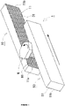
- the thread-rolling flat die 1 is constructed with a stationary side die 10 having a generally cuboid shape which is secured on a designated base, and a moving side die 50 for moving along a predetermined direction with respect to the stationary side die 10.
- the stationary side die 10 has a stationary side thread-rolling surface 11
- the moving side die 50 has a moving side thread-rolling surface 51.
- the stationary side thread-rolling surface 11 and the moving side thread-rolling surface 51 are arranged to face each other, and the workpiece W interposed between the stationary side thread-rolling surface 11 and the moving side thread-rolling surface 51 is subjected to the rolling process to produce a bolt B.
- the moving direction of the moving side die 50 is in parallel with the stationary side thread-rolling surface 11 of the stationary side die 10 and consistent with the rolling direction.
- the dimensions of respective dies 10, 50 are 60 mm in height, 400 mm in width, and 38.4 mm - 38 mm in depth.
- Each of the dies 10, 50 is formed of cold die steel and into the shape described above.
- the workpiece W of the bolt B uses a hard raw material such as chrome molybdenum steel that is heat-treated to reduce the weight.
- the bolt B which is a threaded fastener (product) is a hex screw having the size of M6 x 1.0 16R.
- Each thread-rolling surface 11, 51 is provided with a plurality of processing teeth 31 for forming a processed portion W1 of the workpiece W into a threaded shape.
- the processed portion W1 of the workpiece W is subjected to plastic deformation with the processing teeth 31 to form the threaded portion of the bolt B, while the workpiece W rotates in the direction indicated by an arrow of FIG. 1 . More specifically, the processing teeth 31 form the bottom of the trough in the thread groove of the bolt B as described below.
- pitch of the processing teeth 31 throughout each thread-rolling surface 11, 51 is set to the value equal to the pitch of the thread on the bolt B.
- the stationary side die 10 and the moving side die 50 in this embodiment have the identical shape with each other, and the respective thread-rolling surfaces 11, 51 are symmetric with respect to a point. Therefore, the thread-rolling surfaces 11, 51 are hereinafter described in detail with the same reference numerals.
- the thread-rolling surface 11, 51 of the die 10, 50 in the thread-rolling flat die 1 has a bite surface 12. Also, a finishing surface 13 is provided adjacent to this bite surface 12. Yet, a roll-off surface 14 is provided adjacent to the finishing surface 13.
- a thread-rolling starting point 17 is defined where the workpiece W is supplied.
- the length L0 is determined along the rolling direction from one end 11a to the other end 11b of the die 10, 50 with reference to the thread-rolling starting point 17.
- the bite surface 12 has the inclination which recedes with distance from the finishing surface 13. Such an inclination constitutes an essential portion of the present invention, and will be described in detail below.
- the bite surface 12 is provided with at least a first partial bite surface 15 and a second partial bite surface 16 continuously formed between the first partial bite surface 15 and the finishing surface 13.
- the backward amount that recedes relative to the length L2 (145 mm) is set to be 0.07 mm.
- the angle ⁇ of the first partial bite surface 15 and the angle ⁇ of the second partial bite surface 16 is ⁇ > ⁇ .
- the inclination of the first partial bite surface 15 is preferably constituted with at least 60% or more of the backward amount (mm) relative to the sum of the backward amount (mm) in the first partial bite surface 15 and the backward amount (mm) in the second partial bite surface 16.
- the inclination of the second partial bite surface 16 is preferably constituted with 40% or less of the backward amount (mm) relative to the sum of the backward amount (mm) in the first partial bite surface 15 and the backward amount (mm) in the second partial bite surface 16.
- the lengths L1, L2, and L3 described above have the relationship of L2>L1>L3.
- L1 130 mm
- L2 165 mm
- L3 92 mm.
- the thread-rolling starting point 17 is defined at a 5 mm position separated from one end 11a of the die 10, 50.
- the crest shape of the processing tooth 31 gradually changes from the root side to the crest angle (60°) of the processing tooth 31 in the finishing surface 13.
- the height H of the processing teeth 31 (distances between the trough bottom 33 and the crest 32 of the processing teeth 31) includes a height H1 of the processing tooth 31 in the first partial bite surface 15, a height H3 of the processing tooth 31 in the second partial bite surface 16, and a height H2 of the processing tooth 31 in the finishing surface 13, which have the relationship of H1 ⁇ H3 ⁇ H2.
- the shape of the processing teeth 31 in the finishing surface 13 and the roll-off surface 14 described above has no shape variation within its range and corresponds to the shape of the thread groove in the bolt B.
- the moving side die 50 moves at the constant speed of about 900 mm/sec during the period that the workpiece W moves from the thread-rolling starting point 17 to the finishing surface 13.
- the specific speed can be changed appropriately; however, it is preferable that the speed is maintained constant during the period described above.
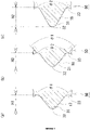
- the structure is suggested such that as shown in FIG. 8(a) , in the stationary side thread-rolling surface 11 on the stationary side die 10, the first partial bite surface 15 is formed into a convex surface shape that rises toward the moving side thread-rolling surface 51, and that as shown in FIG. 8 (b) , the second partial bite surface 16 is formed into a concave surface shape that lowers with respect to the moving side thread-rolling surface 51.
- the stationary side thread-rolling surface 11 in the first partial bite surface 15 is configured with a convex curved line in which the stationary side thread-rolling surface 11 is formed toward the moving side thread-rolling surface 51 when the cross section of the stationary side die 10 is taken along an imaginary line orthogonal to the thread-rolling direction
- the surface 11 in the second partial bite surface 16 is configured with a concave curved line that recedes toward stationary side die 10.
- the first partial bite surface 15 is formed into the concave surface shape that lowers corresponding to the stationary side thread-rolling surface 11
- the second partial bite surface 16 is formed into the convex surface shape that rises corresponding to the stationary side thread-rolling surface 11.
- the structure may be made such that in the stationary side thread-rolling surface 11 on the stationary side die 10, the first partial bite surface 15 is formed into the concave surface shape that lowers with respect to the moving side thread-rolling surface 51, and that the second partial bite surface 16 is formed into the convex surface shape that rises toward the moving side thread-rolling surface 51.
- the first partial bite surface 15 is formed into the convex surface shape that rises corresponding to the stationary side thread-rolling surface 11
- the second partial bite surface 16 is formed into the concave surface shape that lowers corresponding to the stationary side thread-rolling surface 11.
- the present invention is not limited to the embodiments described above, and the shape of the processing tooth 31 may be continuously changed so as to be formed into the desired shape in the finishing surface 13, for example.
- the shape can be appropriately changed under conditions where the crest angle of the processing tooth 31 in the bite surface 12 is larger than the crest angle of the processing tooth 31 in the finishing surface 13.
- the bite surface 12 may be formed with not only two partial bite surfaces 15, 16, but also three or more partial bite surfaces.
- the length L1 of the first partial bite surface 15, the length L2 of the second partial bite surface 16, and the length L3 of the finishing surface 13 preferably have the relationship of L2 > L1 > L3; however, the relationship may be L2 ⁇ L1 > L3.
- the present invention is not intended to actively exclude the configuration of L1 > L2 > L3.
- the moving speed of the moving side die 50 moving at the constant speed is not limited to the speed described above, and it can be defined appropriately and freely in view of processing conditions such as raw materials and dimensions.
- one-way die or two-way die is also applicable.
Landscapes
- Engineering & Computer Science (AREA)
- Mechanical Engineering (AREA)
- Forging (AREA)
- Metal Rolling (AREA)
- Extrusion Of Metal (AREA)
Claims (4)
- Une filière plate de filetage par roulage (1) pour un élément de fixation fileté (B), comprenant une surface de filetage par roulage comprenant au moins une surface de morsure (12) à laquelle une pièce (W) de l'élément de fixation fileté est fournie, une surface de finition (13) formée adjacente à la surface de morsure, et une surface de roulement (14) formée adjacente à la surface de finition, la surface de roulement (14) ayant une inclinaison par rapport à la surface de finition (13),dans laquelle la surface de morsure (12) comprend au moins :une première surface de morsure partielle (15) ayant une inclinaison et un angle α de l'inclinaison par rapport à la surface de finition (13), la première surface de morsure partielle (15) étant une partie pour former sensiblement une rainure de filetage dans une partie traitée de la pièce (W) ; etune deuxième surface de morsure partielle (16) formée en continu entre la première surface de morsure partielle (15) et la surface de finition (13), la deuxième surface de morsure partielle (16) ayant une inclinaison et un angle β de l'inclinaison par rapport à la surface de finition (13), l'angle β étant inférieur à l'angle α ;la filière plate de filetage par roulage étant caractérisée en ce que, dans la première surface de morsure partielle (15) et la deuxième surface de morsure partielle (16), un angle de crête d'une dent de traitement pour former un fond de creux de la rainure de filetage dans l'élément de fixation fileté est plus grand qu'un angle de crête d'une dent de traitement dans la surface de finition (13),dans laquelle une forme de crête de la dent de traitement change progressivement d'un côté du fond à l'angle de crête de la dent de traitement dans la surface de finition (13) le long de la surface de filetage par roulage depuis un point de départ de la première surface de morsure partielle (15) vers la surface de finition (13), etdans laquelle la longueur L1 de la première surface de morsure partielle (15) le long d'une direction de filetage par roulage, la longueur L3 de la surface de finition (13) le long de la direction de filetage par roulage, et la longueur L4 de la surface de roulement (14) le long de la direction de filetage par roulage ont une relation de L1 > L3 > L4.
- La filière plate de filetage par roulage (1) pour un élément de fixation fileté (B) selon la revendication 1, dans laquelle la longueur L1 de la première surface de morsure partielle (15) le long de la direction de filetage par roulage, la longueur L2 de la deuxième surface de morsure partielle (16) le long de la direction de filetage par roulage, et la longueur L3 de la surface de finition (13) le long de la direction de filetage par roulage ont une relation de L2 > L1 > L3.
- La filière plate de filetage par roulage (1) pour un élément de fixation fileté (B) selon la revendication 1 ou 2, dans laquelle l'inclinaison de la première surface de morsure partielle (15) est constituée par la longueur le long de la direction de filetage par roulage dans la première surface de morsure partielle (15) et une quantité en arrière dans la première surface de morsure partielle (15) par rapport à la surface de finition (13),l'inclinaison de la deuxième surface de morsure partielle (16) est constituée par la longueur le long de la direction de filetage par roulage dans la deuxième surface de morsure partielle (16) et une quantité en arrière par rapport à la surface de finition (13), etl'inclinaison de la deuxième surface de morsure partielle (16) est constituée de 40 % ou moins de la quantité en arrière par rapport à une somme de la quantité en arrière dans la première surface de morsure partielle (15) et de la quantité en arrière dans la deuxième surface de morsure partielle (16).
- Un procédé de filetage par roulage, utilisant la filière plate de filetage par roulage (1) pour un élément de fixation fileté (B) selon l'une quelconque des revendications 1 à 3, dans lequel une filière sur un côté mobile de la filière plate de filetage par roulage (1) pour un élément de fixation fileté (B) se déplace à une vitesse constante pendant une période où la pièce se déplace de la première surface de morsure partielle à la surface de finition (13).
Applications Claiming Priority (2)
| Application Number | Priority Date | Filing Date | Title |
|---|---|---|---|
| JP2016056233A JP5979806B1 (ja) | 2016-03-18 | 2016-03-18 | ネジ部品用転造平ダイス、及び転造加工方法 |
| PCT/JP2016/063159 WO2017158853A1 (fr) | 2016-03-18 | 2016-04-27 | Filière plate de calandrage pour élément de vis et procédé de travail de calandrage |
Publications (3)
| Publication Number | Publication Date |
|---|---|
| EP3263244A1 EP3263244A1 (fr) | 2018-01-03 |
| EP3263244A4 EP3263244A4 (fr) | 2018-12-26 |
| EP3263244B1 true EP3263244B1 (fr) | 2022-05-11 |
Family
ID=56820009
Family Applications (1)
| Application Number | Title | Priority Date | Filing Date |
|---|---|---|---|
| EP16894471.8A Active EP3263244B1 (fr) | 2016-03-18 | 2016-04-27 | Filière plate de calandrage pour élément de vis et procédé de travail de calandrage |
Country Status (7)
| Country | Link |
|---|---|
| US (1) | US10118214B2 (fr) |
| EP (1) | EP3263244B1 (fr) |
| JP (1) | JP5979806B1 (fr) |
| KR (1) | KR101789730B1 (fr) |
| CN (1) | CN107530763B (fr) |
| TW (1) | TWI595941B (fr) |
| WO (1) | WO2017158853A1 (fr) |
Families Citing this family (5)
| Publication number | Priority date | Publication date | Assignee | Title |
|---|---|---|---|---|
| WO2020003530A1 (fr) * | 2018-06-29 | 2020-01-02 | 日東精工株式会社 | Matrice plate |
| TWI678267B (zh) * | 2018-09-06 | 2019-12-01 | 川恆技術研究工業股份有限公司 | 工具製造方法 |
| EP4094872B1 (fr) * | 2020-03-26 | 2025-06-18 | OSG Corporation | Matrice de laminage et son procédé de fabrication |
| IT202000032609A1 (it) * | 2020-12-29 | 2022-06-29 | F Lli Mauri Spa | Coppia di utensili di rullatura di tiranti cilindrici e procedimento di rullatura tramite detti utensili |
| KR102556379B1 (ko) * | 2021-11-18 | 2023-07-17 | 주식회사 선일다이파스 | 볼트 가공용 전조 다이스 |
Family Cites Families (16)
| Publication number | Priority date | Publication date | Assignee | Title |
|---|---|---|---|---|
| GB581249A (en) * | 1944-07-15 | 1946-10-07 | Harold Morris | Improvements in or relating to dies for rolling screw threads, serrations and the like |
| US3260100A (en) * | 1963-07-30 | 1966-07-12 | Illinois Tool Works | Apparatus for simultaneously imparting an alternate series of thread forms on a workpiece |
| SU721208A1 (ru) * | 1977-04-11 | 1980-03-15 | Физико-технический институт АН Белорусской ССР | Рейка дл накатывани зубчатых колес |
| US4362045A (en) * | 1980-10-10 | 1982-12-07 | Ex-Cell-O Corporation | Tooth forming tools |
| US4488418A (en) * | 1982-03-11 | 1984-12-18 | Ex-Cell-O Corporation | Apparatus for roll sizing diameters |
| US4798070A (en) * | 1983-07-01 | 1989-01-17 | Colt Industries Operating Corporation | Combined thread rolling dies |
| US4862718A (en) * | 1988-07-14 | 1989-09-05 | Sps Technologies, Inc. | Thread rolling dies |
| CN1046299A (zh) * | 1989-04-14 | 1990-10-24 | 顿河罗斯托夫农业机械制造研究所 | 螺纹滚压用工具 |
| JPH0386343A (ja) * | 1989-08-28 | 1991-04-11 | Sps Technol Inc | ねじ転造ダイス |
| US5243843A (en) | 1991-09-17 | 1993-09-14 | Quamco, Inc. | Thread forming method and apparatus |
| US5182937A (en) * | 1991-09-17 | 1993-02-02 | Quamco, Inc. | Seam-free thread rolling dies |
| JPH10146635A (ja) * | 1996-11-13 | 1998-06-02 | Toyota Motor Corp | 軸部材の外歯転造装置 |
| JP4215324B2 (ja) | 1998-12-15 | 2009-01-28 | レッキス工業株式会社 | 薄肉鋼管用ねじ転造ローラ |
| US6598453B2 (en) | 2000-10-13 | 2003-07-29 | Nachi-Fujikoshi Corp. | Tooth rolling flat dies and method for forming teeth |
| JP4830246B2 (ja) * | 2000-10-13 | 2011-12-07 | 株式会社不二越 | 転造平ダイス及び転造加工方法 |
| JP2005288456A (ja) | 2004-03-31 | 2005-10-20 | Sanmei Seisakusho:Kk | 転造ダイス |
-
2016
- 2016-03-18 JP JP2016056233A patent/JP5979806B1/ja active Active
- 2016-04-27 CN CN201680002074.6A patent/CN107530763B/zh active Active
- 2016-04-27 EP EP16894471.8A patent/EP3263244B1/fr active Active
- 2016-04-27 WO PCT/JP2016/063159 patent/WO2017158853A1/fr not_active Ceased
- 2016-04-27 US US15/567,968 patent/US10118214B2/en active Active
- 2016-04-27 KR KR1020167027905A patent/KR101789730B1/ko active Active
- 2016-05-17 TW TW105115152A patent/TWI595941B/zh active
Also Published As
| Publication number | Publication date |
|---|---|
| JP5979806B1 (ja) | 2016-08-31 |
| JP2017170455A (ja) | 2017-09-28 |
| CN107530763A (zh) | 2018-01-02 |
| US10118214B2 (en) | 2018-11-06 |
| EP3263244A4 (fr) | 2018-12-26 |
| CN107530763B (zh) | 2020-06-05 |
| US20180117664A1 (en) | 2018-05-03 |
| EP3263244A1 (fr) | 2018-01-03 |
| TW201733705A (zh) | 2017-10-01 |
| KR101789730B1 (ko) | 2017-10-25 |
| TWI595941B (zh) | 2017-08-21 |
| WO2017158853A1 (fr) | 2017-09-21 |
Similar Documents
| Publication | Publication Date | Title |
|---|---|---|
| EP3263244B1 (fr) | Filière plate de calandrage pour élément de vis et procédé de travail de calandrage | |
| KR101277383B1 (ko) | 전조다이스 | |
| Ma et al. | Geometric design of the rolling tool for gear roll-forming process with axial-infeed | |
| EP0533456B1 (fr) | Méthode et appareil de formation de filets | |
| US6516650B1 (en) | Rolling dies for producing dog point threads | |
| US5182937A (en) | Seam-free thread rolling dies | |
| RU2451570C1 (ru) | Способ изготовления переменно-гофрированных элементов | |
| CN105008062A (zh) | 用于制造混凝土螺钉的方法 | |
| US8539806B2 (en) | Roll forming method for producing longitudinally toothed profiled bodies in pot-shaped cylindrical workpieces | |
| Tajul et al. | Successive forging of long plate having inclined cross-section | |
| JP2007132398A (ja) | ねじ部品、雄ねじ部品の製造方法および転造ダイス | |
| JP2006187796A (ja) | 転造ダイス、及び、転造ダイスの製造方法 | |
| RU107988U1 (ru) | Инструмент для накатки крупной резьбы | |
| RU2222408C2 (ru) | Способ изготовления болтов с фланцем | |
| RU170342U1 (ru) | Деформирующая клеть | |
| JP6641694B2 (ja) | 内歯ヘリカルギア製造用金型、内歯ヘリカルギアの製造方法、及び、内歯ヘリカルギア製造用ギアブランク | |
| SU1759511A1 (ru) | Инструмент дл накатки резьбы | |
| Jirathearanat et al. | Successive Forming of Multi-thickness Plates by Using Wedge-shaped Tool | |
| Mizuno et al. | Influence of forming conditions on loads in split-forging | |
| JP4827562B2 (ja) | 転造ダイスの製造方法 | |
| JP7356027B2 (ja) | 鍛造装置 | |
| SU1794586A1 (ru) | Способ получения заготовок колец п-образного поперечного сечения | |
| RU180977U1 (ru) | Давильный ролик для раскатки листовых заготовок | |
| RU2630127C1 (ru) | Инструмент для поперечно-клиновой прокатки (варианты) | |
| SU1053939A1 (ru) | Способ изготовлени лезвий на кромках плоских заготовок и устройство дл его осуществлени |
Legal Events
| Date | Code | Title | Description |
|---|---|---|---|
| STAA | Information on the status of an ep patent application or granted ep patent |
Free format text: STATUS: THE INTERNATIONAL PUBLICATION HAS BEEN MADE |
|
| PUAI | Public reference made under article 153(3) epc to a published international application that has entered the european phase |
Free format text: ORIGINAL CODE: 0009012 |
|
| STAA | Information on the status of an ep patent application or granted ep patent |
Free format text: STATUS: REQUEST FOR EXAMINATION WAS MADE |
|
| 17P | Request for examination filed |
Effective date: 20170928 |
|
| AK | Designated contracting states |
Kind code of ref document: A1 Designated state(s): AL AT BE BG CH CY CZ DE DK EE ES FI FR GB GR HR HU IE IS IT LI LT LU LV MC MK MT NL NO PL PT RO RS SE SI SK SM TR |
|
| AX | Request for extension of the european patent |
Extension state: BA ME |
|
| A4 | Supplementary search report drawn up and despatched |
Effective date: 20181126 |
|
| RIC1 | Information provided on ipc code assigned before grant |
Ipc: B21H 3/06 20060101AFI20181120BHEP Ipc: B21H 5/02 20060101ALN20181120BHEP |
|
| DAV | Request for validation of the european patent (deleted) | ||
| DAX | Request for extension of the european patent (deleted) | ||
| GRAP | Despatch of communication of intention to grant a patent |
Free format text: ORIGINAL CODE: EPIDOSNIGR1 |
|
| STAA | Information on the status of an ep patent application or granted ep patent |
Free format text: STATUS: GRANT OF PATENT IS INTENDED |
|
| RIC1 | Information provided on ipc code assigned before grant |
Ipc: B21H 5/02 20060101ALN20211221BHEP Ipc: B21H 3/06 20060101AFI20211221BHEP |
|
| INTG | Intention to grant announced |
Effective date: 20220113 |
|
| GRAS | Grant fee paid |
Free format text: ORIGINAL CODE: EPIDOSNIGR3 |
|
| GRAA | (expected) grant |
Free format text: ORIGINAL CODE: 0009210 |
|
| STAA | Information on the status of an ep patent application or granted ep patent |
Free format text: STATUS: THE PATENT HAS BEEN GRANTED |
|
| AK | Designated contracting states |
Kind code of ref document: B1 Designated state(s): AL AT BE BG CH CY CZ DE DK EE ES FI FR GB GR HR HU IE IS IT LI LT LU LV MC MK MT NL NO PL PT RO RS SE SI SK SM TR |
|
| REG | Reference to a national code |
Ref country code: GB Ref legal event code: FG4D |
|
| REG | Reference to a national code |
Ref country code: CH Ref legal event code: EP |
|
| REG | Reference to a national code |
Ref country code: AT Ref legal event code: REF Ref document number: 1490949 Country of ref document: AT Kind code of ref document: T Effective date: 20220515 |
|
| REG | Reference to a national code |
Ref country code: DE Ref legal event code: R096 Ref document number: 602016072163 Country of ref document: DE |
|
| REG | Reference to a national code |
Ref country code: IE Ref legal event code: FG4D |
|
| REG | Reference to a national code |
Ref country code: LT Ref legal event code: MG9D |
|
| REG | Reference to a national code |
Ref country code: NL Ref legal event code: MP Effective date: 20220511 |
|
| REG | Reference to a national code |
Ref country code: AT Ref legal event code: MK05 Ref document number: 1490949 Country of ref document: AT Kind code of ref document: T Effective date: 20220511 |
|
| PG25 | Lapsed in a contracting state [announced via postgrant information from national office to epo] |
Ref country code: SE Free format text: LAPSE BECAUSE OF FAILURE TO SUBMIT A TRANSLATION OF THE DESCRIPTION OR TO PAY THE FEE WITHIN THE PRESCRIBED TIME-LIMIT Effective date: 20220511 Ref country code: PT Free format text: LAPSE BECAUSE OF FAILURE TO SUBMIT A TRANSLATION OF THE DESCRIPTION OR TO PAY THE FEE WITHIN THE PRESCRIBED TIME-LIMIT Effective date: 20220912 Ref country code: NO Free format text: LAPSE BECAUSE OF FAILURE TO SUBMIT A TRANSLATION OF THE DESCRIPTION OR TO PAY THE FEE WITHIN THE PRESCRIBED TIME-LIMIT Effective date: 20220811 Ref country code: NL Free format text: LAPSE BECAUSE OF FAILURE TO SUBMIT A TRANSLATION OF THE DESCRIPTION OR TO PAY THE FEE WITHIN THE PRESCRIBED TIME-LIMIT Effective date: 20220511 Ref country code: LT Free format text: LAPSE BECAUSE OF FAILURE TO SUBMIT A TRANSLATION OF THE DESCRIPTION OR TO PAY THE FEE WITHIN THE PRESCRIBED TIME-LIMIT Effective date: 20220511 Ref country code: HR Free format text: LAPSE BECAUSE OF FAILURE TO SUBMIT A TRANSLATION OF THE DESCRIPTION OR TO PAY THE FEE WITHIN THE PRESCRIBED TIME-LIMIT Effective date: 20220511 Ref country code: GR Free format text: LAPSE BECAUSE OF FAILURE TO SUBMIT A TRANSLATION OF THE DESCRIPTION OR TO PAY THE FEE WITHIN THE PRESCRIBED TIME-LIMIT Effective date: 20220812 Ref country code: FI Free format text: LAPSE BECAUSE OF FAILURE TO SUBMIT A TRANSLATION OF THE DESCRIPTION OR TO PAY THE FEE WITHIN THE PRESCRIBED TIME-LIMIT Effective date: 20220511 Ref country code: ES Free format text: LAPSE BECAUSE OF FAILURE TO SUBMIT A TRANSLATION OF THE DESCRIPTION OR TO PAY THE FEE WITHIN THE PRESCRIBED TIME-LIMIT Effective date: 20220511 Ref country code: BG Free format text: LAPSE BECAUSE OF FAILURE TO SUBMIT A TRANSLATION OF THE DESCRIPTION OR TO PAY THE FEE WITHIN THE PRESCRIBED TIME-LIMIT Effective date: 20220811 Ref country code: AT Free format text: LAPSE BECAUSE OF FAILURE TO SUBMIT A TRANSLATION OF THE DESCRIPTION OR TO PAY THE FEE WITHIN THE PRESCRIBED TIME-LIMIT Effective date: 20220511 |
|
| PG25 | Lapsed in a contracting state [announced via postgrant information from national office to epo] |
Ref country code: RS Free format text: LAPSE BECAUSE OF FAILURE TO SUBMIT A TRANSLATION OF THE DESCRIPTION OR TO PAY THE FEE WITHIN THE PRESCRIBED TIME-LIMIT Effective date: 20220511 Ref country code: PL Free format text: LAPSE BECAUSE OF FAILURE TO SUBMIT A TRANSLATION OF THE DESCRIPTION OR TO PAY THE FEE WITHIN THE PRESCRIBED TIME-LIMIT Effective date: 20220511 Ref country code: LV Free format text: LAPSE BECAUSE OF FAILURE TO SUBMIT A TRANSLATION OF THE DESCRIPTION OR TO PAY THE FEE WITHIN THE PRESCRIBED TIME-LIMIT Effective date: 20220511 Ref country code: IS Free format text: LAPSE BECAUSE OF FAILURE TO SUBMIT A TRANSLATION OF THE DESCRIPTION OR TO PAY THE FEE WITHIN THE PRESCRIBED TIME-LIMIT Effective date: 20220911 |
|
| PG25 | Lapsed in a contracting state [announced via postgrant information from national office to epo] |
Ref country code: SM Free format text: LAPSE BECAUSE OF FAILURE TO SUBMIT A TRANSLATION OF THE DESCRIPTION OR TO PAY THE FEE WITHIN THE PRESCRIBED TIME-LIMIT Effective date: 20220511 Ref country code: SK Free format text: LAPSE BECAUSE OF FAILURE TO SUBMIT A TRANSLATION OF THE DESCRIPTION OR TO PAY THE FEE WITHIN THE PRESCRIBED TIME-LIMIT Effective date: 20220511 Ref country code: RO Free format text: LAPSE BECAUSE OF FAILURE TO SUBMIT A TRANSLATION OF THE DESCRIPTION OR TO PAY THE FEE WITHIN THE PRESCRIBED TIME-LIMIT Effective date: 20220511 Ref country code: EE Free format text: LAPSE BECAUSE OF FAILURE TO SUBMIT A TRANSLATION OF THE DESCRIPTION OR TO PAY THE FEE WITHIN THE PRESCRIBED TIME-LIMIT Effective date: 20220511 Ref country code: DK Free format text: LAPSE BECAUSE OF FAILURE TO SUBMIT A TRANSLATION OF THE DESCRIPTION OR TO PAY THE FEE WITHIN THE PRESCRIBED TIME-LIMIT Effective date: 20220511 Ref country code: CZ Free format text: LAPSE BECAUSE OF FAILURE TO SUBMIT A TRANSLATION OF THE DESCRIPTION OR TO PAY THE FEE WITHIN THE PRESCRIBED TIME-LIMIT Effective date: 20220511 |
|
| REG | Reference to a national code |
Ref country code: DE Ref legal event code: R097 Ref document number: 602016072163 Country of ref document: DE |
|
| PLBE | No opposition filed within time limit |
Free format text: ORIGINAL CODE: 0009261 |
|
| STAA | Information on the status of an ep patent application or granted ep patent |
Free format text: STATUS: NO OPPOSITION FILED WITHIN TIME LIMIT |
|
| PG25 | Lapsed in a contracting state [announced via postgrant information from national office to epo] |
Ref country code: AL Free format text: LAPSE BECAUSE OF FAILURE TO SUBMIT A TRANSLATION OF THE DESCRIPTION OR TO PAY THE FEE WITHIN THE PRESCRIBED TIME-LIMIT Effective date: 20220511 |
|
| 26N | No opposition filed |
Effective date: 20230214 |
|
| PG25 | Lapsed in a contracting state [announced via postgrant information from national office to epo] |
Ref country code: SI Free format text: LAPSE BECAUSE OF FAILURE TO SUBMIT A TRANSLATION OF THE DESCRIPTION OR TO PAY THE FEE WITHIN THE PRESCRIBED TIME-LIMIT Effective date: 20220511 |
|
| REG | Reference to a national code |
Ref country code: CH Ref legal event code: PL |
|
| GBPC | Gb: european patent ceased through non-payment of renewal fee |
Effective date: 20230427 |
|
| PG25 | Lapsed in a contracting state [announced via postgrant information from national office to epo] |
Ref country code: LU Free format text: LAPSE BECAUSE OF NON-PAYMENT OF DUE FEES Effective date: 20230427 |
|
| REG | Reference to a national code |
Ref country code: BE Ref legal event code: MM Effective date: 20230430 |
|
| PG25 | Lapsed in a contracting state [announced via postgrant information from national office to epo] |
Ref country code: MC Free format text: LAPSE BECAUSE OF FAILURE TO SUBMIT A TRANSLATION OF THE DESCRIPTION OR TO PAY THE FEE WITHIN THE PRESCRIBED TIME-LIMIT Effective date: 20220511 |
|
| PG25 | Lapsed in a contracting state [announced via postgrant information from national office to epo] |
Ref country code: GB Free format text: LAPSE BECAUSE OF NON-PAYMENT OF DUE FEES Effective date: 20230427 |
|
| PG25 | Lapsed in a contracting state [announced via postgrant information from national office to epo] |
Ref country code: MC Free format text: LAPSE BECAUSE OF FAILURE TO SUBMIT A TRANSLATION OF THE DESCRIPTION OR TO PAY THE FEE WITHIN THE PRESCRIBED TIME-LIMIT Effective date: 20220511 Ref country code: LI Free format text: LAPSE BECAUSE OF NON-PAYMENT OF DUE FEES Effective date: 20230430 Ref country code: GB Free format text: LAPSE BECAUSE OF NON-PAYMENT OF DUE FEES Effective date: 20230427 Ref country code: CH Free format text: LAPSE BECAUSE OF NON-PAYMENT OF DUE FEES Effective date: 20230430 |
|
| REG | Reference to a national code |
Ref country code: IE Ref legal event code: MM4A |
|
| PG25 | Lapsed in a contracting state [announced via postgrant information from national office to epo] |
Ref country code: BE Free format text: LAPSE BECAUSE OF NON-PAYMENT OF DUE FEES Effective date: 20230430 |
|
| PG25 | Lapsed in a contracting state [announced via postgrant information from national office to epo] |
Ref country code: IE Free format text: LAPSE BECAUSE OF NON-PAYMENT OF DUE FEES Effective date: 20230427 |
|
| PG25 | Lapsed in a contracting state [announced via postgrant information from national office to epo] |
Ref country code: IE Free format text: LAPSE BECAUSE OF NON-PAYMENT OF DUE FEES Effective date: 20230427 |
|
| PG25 | Lapsed in a contracting state [announced via postgrant information from national office to epo] |
Ref country code: BG Free format text: LAPSE BECAUSE OF FAILURE TO SUBMIT A TRANSLATION OF THE DESCRIPTION OR TO PAY THE FEE WITHIN THE PRESCRIBED TIME-LIMIT Effective date: 20220511 |
|
| PG25 | Lapsed in a contracting state [announced via postgrant information from national office to epo] |
Ref country code: BG Free format text: LAPSE BECAUSE OF FAILURE TO SUBMIT A TRANSLATION OF THE DESCRIPTION OR TO PAY THE FEE WITHIN THE PRESCRIBED TIME-LIMIT Effective date: 20220511 |
|
| PGFP | Annual fee paid to national office [announced via postgrant information from national office to epo] |
Ref country code: DE Payment date: 20250422 Year of fee payment: 10 |
|
| PGFP | Annual fee paid to national office [announced via postgrant information from national office to epo] |
Ref country code: IT Payment date: 20250411 Year of fee payment: 10 |
|
| PG25 | Lapsed in a contracting state [announced via postgrant information from national office to epo] |
Ref country code: CY Free format text: LAPSE BECAUSE OF FAILURE TO SUBMIT A TRANSLATION OF THE DESCRIPTION OR TO PAY THE FEE WITHIN THE PRESCRIBED TIME-LIMIT; INVALID AB INITIO Effective date: 20160427 |
|
| PG25 | Lapsed in a contracting state [announced via postgrant information from national office to epo] |
Ref country code: HU Free format text: LAPSE BECAUSE OF FAILURE TO SUBMIT A TRANSLATION OF THE DESCRIPTION OR TO PAY THE FEE WITHIN THE PRESCRIBED TIME-LIMIT; INVALID AB INITIO Effective date: 20160427 |
|
| PG25 | Lapsed in a contracting state [announced via postgrant information from national office to epo] |
Ref country code: TR Free format text: LAPSE BECAUSE OF FAILURE TO SUBMIT A TRANSLATION OF THE DESCRIPTION OR TO PAY THE FEE WITHIN THE PRESCRIBED TIME-LIMIT Effective date: 20220511 |
|
| PGFP | Annual fee paid to national office [announced via postgrant information from national office to epo] |
Ref country code: FR Payment date: 20260320 Year of fee payment: 11 |