EP3263259A1 - Spitzensäge für verbundwerkstoff - Google Patents
Spitzensäge für verbundwerkstoff Download PDFInfo
- Publication number
- EP3263259A1 EP3263259A1 EP16199619.4A EP16199619A EP3263259A1 EP 3263259 A1 EP3263259 A1 EP 3263259A1 EP 16199619 A EP16199619 A EP 16199619A EP 3263259 A1 EP3263259 A1 EP 3263259A1
- Authority
- EP
- European Patent Office
- Prior art keywords
- tip
- saw
- tip saw
- composite material
- base
- Prior art date
- Legal status (The legal status is an assumption and is not a legal conclusion. Google has not performed a legal analysis and makes no representation as to the accuracy of the status listed.)
- Granted
Links
Images





Classifications
-
- B—PERFORMING OPERATIONS; TRANSPORTING
- B23—MACHINE TOOLS; METAL-WORKING NOT OTHERWISE PROVIDED FOR
- B23D—PLANING; SLOTTING; SHEARING; BROACHING; SAWING; FILING; SCRAPING; LIKE OPERATIONS FOR WORKING METAL BY REMOVING MATERIAL, NOT OTHERWISE PROVIDED FOR
- B23D61/00—Tools for sawing machines or sawing devices; Clamping devices for these tools
- B23D61/02—Circular saw blades
- B23D61/021—Types of set; Variable teeth, e.g. variable in height or gullet depth; Varying pitch; Details of gullet
-
- B—PERFORMING OPERATIONS; TRANSPORTING
- B23—MACHINE TOOLS; METAL-WORKING NOT OTHERWISE PROVIDED FOR
- B23D—PLANING; SLOTTING; SHEARING; BROACHING; SAWING; FILING; SCRAPING; LIKE OPERATIONS FOR WORKING METAL BY REMOVING MATERIAL, NOT OTHERWISE PROVIDED FOR
- B23D61/00—Tools for sawing machines or sawing devices; Clamping devices for these tools
- B23D61/02—Circular saw blades
- B23D61/04—Circular saw blades with inserted saw teeth, i.e. the teeth being individually inserted
Definitions
- the present invention relates to a tip saw for cutting a composite material such as a sandwich panel made up of a honeycomb core material and face sheets spread on both faces thereof and a fiber reinforced plastic, such as a CFRP or a GFRP, including a resin as its matrix and including carbon fibers, glass fibers, or the like as its filler.
- a composite material such as a sandwich panel made up of a honeycomb core material and face sheets spread on both faces thereof and a fiber reinforced plastic, such as a CFRP or a GFRP, including a resin as its matrix and including carbon fibers, glass fibers, or the like as its filler.
- Sandwich panels are, in greater detail, lightweight and high-strength structural materials made up of a honeycomb core material having a honeycomb structure that is an assembly of hexagonal cells and flat face sheets spread on both faces of the honeycomb core material via a glue or the like, and have been used in a variety of fields such as transportation equipment including automobiles and aircraft and building construction materials in houses and various facilities.
- Fiber reinforced plastics are composite materials for which a filler such as glass fiber is mixed in a matrix such as a thermosetting resin and a thermoplastic resin and molded, are relatively low-cost and lightweight and also excellent in physical strength, and therefore have been widely used for boats, bathtubs, various tanks, etc.
- a filler such as glass fiber
- a matrix such as a thermosetting resin and a thermoplastic resin and molded
- CFRPs carbon fiber reinforced plastics
- the composite material such as a sandwich panel and a fiber reinforced plastic described above is made up of a plurality of different component materials, it is difficult to grind and cut these component materials in a batch manner because of the difference in the hardness, shape, composition, etc., thereof and therefore, so-called burrs, fluffing, surface delamination, etc., are likely to occur at the cut part.
- the face sheets at both sides are high in hardness and have high strength, whereas the strength of the internal honeycomb core material is low.
- the internal fibers (filler) have high strength, whereas the strength of the resin being the base material (matrix) is low. It is not easy to uniformly grind and cut such composite materials. Therefore, in the sandwich panel, burrs and deformation are likely to occur at the time of its grinding and cutting, and collapse and the like of the honeycomb core material is also likely to occur.
- the fiber reinforced plastic melting of the base material, fluffing of the fibers, surface delamination, etc., are likely to occur.
- the present invention aims to solve the variety of problems described above collectively, for a tip saw for a composite material for a fiber reinforced plastic such as a CFRP or a composite material such as a sandwich panel with a honeycomb structural material sandwiched, so as to enable easily performing excellent grinding and cutting.
- Another object of the present invention is to make chips of a composite material move toward the center in a tip thickness direction at the time of its grinding and cutting to thereby prevent the chips from colliding against the composite material during grinding to damage the part concerned.
- the present invention provides a tip saw for a composite material, the tip saw being provided with bases that are formed at a predetermined interval on an outer periphery of a disk-shaped base metal and a single tip that is securely attached to each base, in which flank faces of the tips are provided as staggered teeth pointed alternately at left and right ends, said staggered teeth being composed of inclined surfaces descending from a left end to a right end and from a right end to a left end, respectively, as viewed in a rotation direction of said tip saw, and rake faces are provided as staggered teeth pointed alternately at left and right ends, said staggered teeth being composed of inclined surfaces descending from a left end to a right end and from a right end to a left end, respectively, as viewed in a radial direction of said tip saw, and the rake face of each tip is provided at a negative angle of inclination in a direction opposite to the rotation direction of said tip saw with reference to a center line extending from a center of the base metal toward the
- composite material(s) connote all composites for which two types or more of mutually different materials are combined such as sandwich panels and fiber reinforced plastics.
- a tip saw 1 for a composite material is produced by forming saw blades 3 at fixed intervals on the outer periphery of a disk-shaped base metal 2 and securely attaching tips 5 to bases 4 formed on the respective saw blades 3.
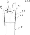
- the tips 5, in the present embodiment, show substantially longitudinal rectangular shapes, and have, in the saw blades 3 that are inclined from one side to the other side of the base metal 2 and adjacent to each other, cutting edges B1 and B2 located at opposite sides to each other. Moreover, a front portion of the tip 5 is provided as a rake face 5a, a top portion 5b of the tip 5 is provided as a flank face, and a rear portion 5c and a bottom portion 5d of the tip 5 are joined to the base 4.
- the adjacent saw blades 3 have a pitch P of approximately 4.0 mm or more therebetween.
- flank faces 5b of the adjacent tips 5 are provided as staggered teeth pointed alternately at their left and right ends which are composed of inclined surfaces descending from its left end to right end and from its right end to left end, respectively, as viewed in a rotation direction A of said tip saw 1.
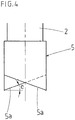
- the rake faces 5a of the adjacent tips 5 are provided as staggered teeth pointed alternately at their left and right ends which are composed of inclined surfaces descending from its left end to right end and from its right end to left end, respectively, as viewed in a radial direction C of said tip saw 1, and are provided at a negative angle ⁇ of inclination in a direction opposite to the rotation direction A of said tip saw 1 with reference to a center line CL extending from a center of the base metal 2 toward the outer periphery.
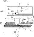
- the base 4 is formed in a substantially L-shape in a lateral view on the saw blade 3 bulging outward from an outer edge of the base metal 2. Moreover, as shown in Fig. 5(a) , at the time of grinding of a fiber reinforced plastic W being a workpiece material, because the flank faces 5b of the tips 5 are provided as staggered teeth, cutting-in by the left and right cutting edges B1 and B2 is performed alternately in a well-balanced manner, and the pointed cutting edges B1 and B2 operate in cooperation to cut the filler (fibers) of the fiber reinforced plastic W while further cutting in the same to grind the matrix (resin). As a result, no fluffing or surface delamination occurs in the fiber reinforced plastic W being a workpiece material.
- the rake faces 5a of the tips 5 are provided as staggered teeth pointed alternately at their left and right ends which are composed of inclined surfaces descending from its left end to right end and from its right end to left end, respectively, as viewed in a radial direction C of said tip saw 1, chips D move to the inside I (toward the center in a tip thickness direction).
- a tip saw 21 is produced by forming bases 24 at fixed intervals on the outer periphery of a disk-shaped base metal 22 and securely attaching tips 25 to the bases 24.
- Each tip 25 is formed in a substantially fan shape, and has, with respect to a cutting edge B as a vertex, a radial portion 25a at a front side provided as a rake face and a radial portion 25b at a rear side provided as a flank face, and has a convex arcuate portion 25c connecting both radial portions 25a and 25b provided as a secure attaching portion.
- the convex arcuate portion 25c of the tip 25 is securely attached by brazing or the like to the base 24 in a concave arc shape on the outer periphery of the base metal 22.
- the adjacent tips 25 have a pitch P of less than approximately 4.5 mm therebetween.
- the rake faces 25a of the tips 25 are provided at a negative angle ⁇ of inclination in a direction opposite to a rotation direction A of said tip saw 21 with reference to a center line CL extending from a center of the base metal 22 toward the outer periphery.
- Each of the concave arc-shaped bases 24 in the tip saw 21 of the present embodiment is in a form recessed from the outer periphery of the disk-shaped base 22 toward the center. Moreover, by the substantially fan-shaped tips 25 described above being securely attached to the bases 24, a gullet 26 is formed between the adjacent tips 25.
- the pitch P of the adjacent tips in said tip saw 21 is, more preferably, on the order of 3.5 mm to 3.0 mm. Therefore, the pitch can be made considerably narrower than that of the adjacent tips 5 in the tip saw 1 of the embodiment described above.
- the rake faces 25a and the flank faces 25b of the tips 25 on the outer periphery of the base metal 22 are both provided as staggered teeth pointed alternately at their left and right ends which are composed of inclined surfaces descending from its left end to right end and from its right end to left end, respectively.
- said tip saw 21 is configured, as described above, with the tips 25 being in substantially fan shapes, the radial portions 25a at a front side provided as rake faces, the radial portions 25b at a rear side provided as flank faces, and the convex arcuate portions 25c connecting both radial portions 25a and 25b securely attached to the concave arc-shaped bases 24 formed at fixed intervals on the outer periphery of the base metal 22, when heating a center part of the tip 25 for joining said tip 25 to the concave arc-shaped base 24, the heat is dissipated uniformly and efficiently to the base 24 of the base metal 22 via the convex arcuate portion 25c of said tip 25, and thus the thermal effect on the outer periphery of the base metal 22 is suppressed to the minimum.
- the tip saw 21 can perform grinding in a stable manner, even when the thickness of a composite material such as a CFRP (Carbon Fiber Reinforced Plastic) is a very thin sheet thickness of less than 3 mm or not more than 1 mm, without vibrating the composite material. Moreover, in this case, even when the matrix of the composite material is a thermoplastic, the tip saw 21 can, because of having tips with the minimum pitch as described above, prevent the thermoplastic from welding by efficient heat dissipation to reliably perform a grinding operation.
- CFRP Carbon Fiber Reinforced Plastic
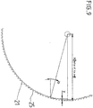
- the cutting edge angle and the angle ⁇ of the FRP sheet can become 90° at a position with an angle of ⁇ .
- the angle between the cutting edge and sheet accordingly becomes 90° when the distance from the cutting edge to the center of a sheet thickness is 13.40 mm, and the cutting edge of the tip perpendicularly abuts against the workpiece material to enable cutting. As a result, sharp grinding can be realized.
Landscapes
- Engineering & Computer Science (AREA)
- Mechanical Engineering (AREA)
- Nonmetal Cutting Devices (AREA)
- Polishing Bodies And Polishing Tools (AREA)
Applications Claiming Priority (1)
| Application Number | Priority Date | Filing Date | Title |
|---|---|---|---|
| JP2016130950A JP6583921B2 (ja) | 2016-06-30 | 2016-06-30 | コンポジット材用チップソー |
Publications (2)
| Publication Number | Publication Date |
|---|---|
| EP3263259A1 true EP3263259A1 (de) | 2018-01-03 |
| EP3263259B1 EP3263259B1 (de) | 2023-07-12 |
Family
ID=57354229
Family Applications (1)
| Application Number | Title | Priority Date | Filing Date |
|---|---|---|---|
| EP16199619.4A Active EP3263259B1 (de) | 2016-06-30 | 2016-11-18 | Spitzensäge für verbundwerkstoff |
Country Status (3)
| Country | Link |
|---|---|
| US (1) | US9981329B2 (de) |
| EP (1) | EP3263259B1 (de) |
| JP (1) | JP6583921B2 (de) |
Families Citing this family (3)
| Publication number | Priority date | Publication date | Assignee | Title |
|---|---|---|---|---|
| EP3530392B1 (de) * | 2016-10-18 | 2022-06-15 | Kanefusa Kabushiki Kaisha | Kreissägeblätter mit mit spitzen |
| SE542030C2 (en) * | 2017-11-22 | 2020-02-11 | Swedex Ab | Saw blade for circular saw and use of such saw blade in a brush cutter |
| JP7774389B2 (ja) * | 2021-03-16 | 2025-11-21 | 株式会社プロテリアル | 電線の製造方法 |
Citations (4)
| Publication number | Priority date | Publication date | Assignee | Title |
|---|---|---|---|---|
| US5351595A (en) * | 1991-12-20 | 1994-10-04 | Vermont American Corporation | Thin kerf circular saw blade |
| WO2000043179A9 (en) * | 1999-01-25 | 2001-08-30 | Black & Decker Inc | Saw blade for cutting fiber cement |
| US20150000497A1 (en) * | 2013-06-27 | 2015-01-01 | Irwin Industrial Tool Company | Saw blade and saw blade tooth construction |
| JP2015168008A (ja) * | 2014-03-04 | 2015-09-28 | 有限会社クローバーテック | 複合材料用チップソー |
Family Cites Families (23)
| Publication number | Priority date | Publication date | Assignee | Title |
|---|---|---|---|---|
| US4060880A (en) * | 1975-06-16 | 1977-12-06 | The Motch And Merryweather Machinery Company | Circular saw having an improved tooth geometry and method of making the same |
| US4463645A (en) * | 1983-02-22 | 1984-08-07 | Speedcut, Inc. | Circular saw |
| JPS59132723U (ja) * | 1983-02-24 | 1984-09-05 | 兼房刃物工業株式会社 | チツプソ− |
| US4690024A (en) * | 1985-02-28 | 1987-09-01 | Black & Decker Inc. | Saw blade and tip therefor |
| DE3943321A1 (de) * | 1988-12-29 | 1990-07-05 | Ryobi Ltd | Schneideinsaetze fuer kreissaegeblaetter |
| JPH0760649A (ja) | 1993-08-24 | 1995-03-07 | Matsushita Electric Ind Co Ltd | 研削切断用砥石 |
| JPH08281606A (ja) * | 1995-04-11 | 1996-10-29 | Osaka Diamond Ind Co Ltd | チップソー及び切削方法 |
| JP3212951B2 (ja) * | 1998-10-22 | 2001-09-25 | 兼房株式会社 | 分割切削型チップソー |
| JP4754260B2 (ja) * | 2005-04-28 | 2011-08-24 | 天龍製鋸株式会社 | 丸鋸 |
| CN100406177C (zh) * | 2005-11-02 | 2008-07-30 | 天龙制锯株式会社 | 旋转锯 |
| US20080257127A1 (en) * | 2007-04-17 | 2008-10-23 | The M. K. Morse Company | Saw blade |
| WO2008149824A1 (ja) * | 2007-06-01 | 2008-12-11 | Onward Ceramic Coating Co., Ltd. | Dlc被覆工具 |
| JP2011045983A (ja) * | 2009-08-28 | 2011-03-10 | Yamazaki Kiko Kk | チップソー |
| US8381625B2 (en) * | 2010-02-16 | 2013-02-26 | Freud America, Inc. | Circular saw blade with cutting tips mechanically locked against multiple force vectors |
| JP5794654B2 (ja) * | 2010-06-08 | 2015-10-14 | 株式会社谷テック | 極薄チップソー |
| JP2012187701A (ja) | 2011-03-08 | 2012-10-04 | Osamu Kobayashi | チップソー |
| JP2012206212A (ja) | 2011-03-30 | 2012-10-25 | Allied Material Corp | サーキュラーソー |
| WO2013098963A1 (ja) * | 2011-12-27 | 2013-07-04 | 株式会社谷テック | 金属切断用チップソー |
| JP6339764B2 (ja) * | 2013-02-25 | 2018-06-06 | 兼房株式会社 | 丸鋸 |
| JP2015020271A (ja) | 2013-07-19 | 2015-02-02 | 株式会社トリガー | チップソーのチップ掬い面研磨方法及びその装置 |
| JP2015123574A (ja) * | 2013-12-27 | 2015-07-06 | 兼房株式会社 | カッター |
| JP6058575B2 (ja) | 2014-03-19 | 2017-01-11 | 株式会社スギノマシン | ウォータージェット切断方法及びウォータージェット切断装置 |
| JP6257105B2 (ja) * | 2016-02-12 | 2018-01-10 | 有限会社クローバーテック | 複合材料用チップソー |
-
2016
- 2016-06-30 JP JP2016130950A patent/JP6583921B2/ja active Active
- 2016-11-18 EP EP16199619.4A patent/EP3263259B1/de active Active
- 2016-11-18 US US15/356,286 patent/US9981329B2/en active Active
Patent Citations (4)
| Publication number | Priority date | Publication date | Assignee | Title |
|---|---|---|---|---|
| US5351595A (en) * | 1991-12-20 | 1994-10-04 | Vermont American Corporation | Thin kerf circular saw blade |
| WO2000043179A9 (en) * | 1999-01-25 | 2001-08-30 | Black & Decker Inc | Saw blade for cutting fiber cement |
| US20150000497A1 (en) * | 2013-06-27 | 2015-01-01 | Irwin Industrial Tool Company | Saw blade and saw blade tooth construction |
| JP2015168008A (ja) * | 2014-03-04 | 2015-09-28 | 有限会社クローバーテック | 複合材料用チップソー |
Also Published As
| Publication number | Publication date |
|---|---|
| JP6583921B2 (ja) | 2019-10-02 |
| US20180001402A1 (en) | 2018-01-04 |
| EP3263259B1 (de) | 2023-07-12 |
| US9981329B2 (en) | 2018-05-29 |
| JP2018001335A (ja) | 2018-01-11 |
Similar Documents
| Publication | Publication Date | Title |
|---|---|---|
| US9981329B2 (en) | Tip saw for composite material | |
| JP5474032B2 (ja) | 回転切削工具 | |
| US20190299304A1 (en) | Special end cutting edge attached cutter for carbon fiber reinforced polymer/plastic with designable micro-tooth configuration | |
| US20150135915A1 (en) | Saw Blade For An Oscillatingly Driven Saw | |
| EP1871560B1 (de) | Sägenblatt | |
| JPWO2009122937A1 (ja) | エンドミル | |
| US20090126712A1 (en) | Stone Saw Blade | |
| WO2005102575A2 (en) | Reciprocating saw blade with tapered tang stem | |
| EP1637264A1 (de) | Kreissägeblatt aus Verbundwerkstoff | |
| CN113477997B (zh) | 一种加工吸波蜂窝的超声弧刃锯片铣刀 | |
| CA2942489C (en) | Apparatus and methods of producing a planar member from sections | |
| US4440532A (en) | Drill bit for drilling holes in composite fiber/resin laminates | |
| CA2634429A1 (en) | Saw blade tooth geometry for circular saw blade | |
| JP5950419B2 (ja) | 複合材料用チップソー | |
| CN210525162U (zh) | 切割锯 | |
| JPH0832382B2 (ja) | ニック付切削工具 | |
| JP2014046376A (ja) | ミリング加工工具を用いた複合材料成形物のトリミング方法 | |
| WO2018193791A1 (ja) | 電動工具用回転鋸 | |
| CN209614435U (zh) | 一种冷锯 | |
| TWI623401B (zh) | Composite blade set and cutting mechanism thereof | |
| JP6257105B2 (ja) | 複合材料用チップソー | |
| EP1082195B1 (de) | Schneidescheibe mit schwingungsdämpfender folie | |
| JP6168521B2 (ja) | 繊維強化樹脂積層体部品の切削加工による製造方法 | |
| EP1882539A1 (de) | Sägeblatt zum Schneiden eines Zementbrettes | |
| US20240416441A1 (en) | Saw blade |
Legal Events
| Date | Code | Title | Description |
|---|---|---|---|
| PUAI | Public reference made under article 153(3) epc to a published international application that has entered the european phase |
Free format text: ORIGINAL CODE: 0009012 |
|
| STAA | Information on the status of an ep patent application or granted ep patent |
Free format text: STATUS: THE APPLICATION HAS BEEN PUBLISHED |
|
| AK | Designated contracting states |
Kind code of ref document: A1 Designated state(s): AL AT BE BG CH CY CZ DE DK EE ES FI FR GB GR HR HU IE IS IT LI LT LU LV MC MK MT NL NO PL PT RO RS SE SI SK SM TR |
|
| AX | Request for extension of the european patent |
Extension state: BA ME |
|
| STAA | Information on the status of an ep patent application or granted ep patent |
Free format text: STATUS: REQUEST FOR EXAMINATION WAS MADE |
|
| 17P | Request for examination filed |
Effective date: 20180703 |
|
| RBV | Designated contracting states (corrected) |
Designated state(s): AL AT BE BG CH CY CZ DE DK EE ES FI FR GB GR HR HU IE IS IT LI LT LU LV MC MK MT NL NO PL PT RO RS SE SI SK SM TR |
|
| STAA | Information on the status of an ep patent application or granted ep patent |
Free format text: STATUS: EXAMINATION IS IN PROGRESS |
|
| 17Q | First examination report despatched |
Effective date: 20210421 |
|
| GRAP | Despatch of communication of intention to grant a patent |
Free format text: ORIGINAL CODE: EPIDOSNIGR1 |
|
| STAA | Information on the status of an ep patent application or granted ep patent |
Free format text: STATUS: GRANT OF PATENT IS INTENDED |
|
| INTG | Intention to grant announced |
Effective date: 20230209 |
|
| GRAS | Grant fee paid |
Free format text: ORIGINAL CODE: EPIDOSNIGR3 |
|
| GRAA | (expected) grant |
Free format text: ORIGINAL CODE: 0009210 |
|
| STAA | Information on the status of an ep patent application or granted ep patent |
Free format text: STATUS: THE PATENT HAS BEEN GRANTED |
|
| AK | Designated contracting states |
Kind code of ref document: B1 Designated state(s): AL AT BE BG CH CY CZ DE DK EE ES FI FR GB GR HR HU IE IS IT LI LT LU LV MC MK MT NL NO PL PT RO RS SE SI SK SM TR |
|
| REG | Reference to a national code |
Ref country code: CH Ref legal event code: EP |
|
| REG | Reference to a national code |
Ref country code: IE Ref legal event code: FG4D |
|
| REG | Reference to a national code |
Ref country code: DE Ref legal event code: R096 Ref document number: 602016080947 Country of ref document: DE |
|
| REG | Reference to a national code |
Ref country code: LT Ref legal event code: MG9D |
|
| REG | Reference to a national code |
Ref country code: NL Ref legal event code: MP Effective date: 20230712 |
|
| REG | Reference to a national code |
Ref country code: AT Ref legal event code: MK05 Ref document number: 1586585 Country of ref document: AT Kind code of ref document: T Effective date: 20230712 |
|
| PG25 | Lapsed in a contracting state [announced via postgrant information from national office to epo] |
Ref country code: NL Free format text: LAPSE BECAUSE OF FAILURE TO SUBMIT A TRANSLATION OF THE DESCRIPTION OR TO PAY THE FEE WITHIN THE PRESCRIBED TIME-LIMIT Effective date: 20230712 |
|
| PG25 | Lapsed in a contracting state [announced via postgrant information from national office to epo] |
Ref country code: GR Free format text: LAPSE BECAUSE OF FAILURE TO SUBMIT A TRANSLATION OF THE DESCRIPTION OR TO PAY THE FEE WITHIN THE PRESCRIBED TIME-LIMIT Effective date: 20231013 |
|
| PG25 | Lapsed in a contracting state [announced via postgrant information from national office to epo] |
Ref country code: ES Free format text: LAPSE BECAUSE OF FAILURE TO SUBMIT A TRANSLATION OF THE DESCRIPTION OR TO PAY THE FEE WITHIN THE PRESCRIBED TIME-LIMIT Effective date: 20230712 |
|
| PG25 | Lapsed in a contracting state [announced via postgrant information from national office to epo] |
Ref country code: IS Free format text: LAPSE BECAUSE OF FAILURE TO SUBMIT A TRANSLATION OF THE DESCRIPTION OR TO PAY THE FEE WITHIN THE PRESCRIBED TIME-LIMIT Effective date: 20231112 |
|
| PG25 | Lapsed in a contracting state [announced via postgrant information from national office to epo] |
Ref country code: SE Free format text: LAPSE BECAUSE OF FAILURE TO SUBMIT A TRANSLATION OF THE DESCRIPTION OR TO PAY THE FEE WITHIN THE PRESCRIBED TIME-LIMIT Effective date: 20230712 Ref country code: RS Free format text: LAPSE BECAUSE OF FAILURE TO SUBMIT A TRANSLATION OF THE DESCRIPTION OR TO PAY THE FEE WITHIN THE PRESCRIBED TIME-LIMIT Effective date: 20230712 Ref country code: PT Free format text: LAPSE BECAUSE OF FAILURE TO SUBMIT A TRANSLATION OF THE DESCRIPTION OR TO PAY THE FEE WITHIN THE PRESCRIBED TIME-LIMIT Effective date: 20231113 Ref country code: NO Free format text: LAPSE BECAUSE OF FAILURE TO SUBMIT A TRANSLATION OF THE DESCRIPTION OR TO PAY THE FEE WITHIN THE PRESCRIBED TIME-LIMIT Effective date: 20231012 Ref country code: LV Free format text: LAPSE BECAUSE OF FAILURE TO SUBMIT A TRANSLATION OF THE DESCRIPTION OR TO PAY THE FEE WITHIN THE PRESCRIBED TIME-LIMIT Effective date: 20230712 Ref country code: LT Free format text: LAPSE BECAUSE OF FAILURE TO SUBMIT A TRANSLATION OF THE DESCRIPTION OR TO PAY THE FEE WITHIN THE PRESCRIBED TIME-LIMIT Effective date: 20230712 Ref country code: IS Free format text: LAPSE BECAUSE OF FAILURE TO SUBMIT A TRANSLATION OF THE DESCRIPTION OR TO PAY THE FEE WITHIN THE PRESCRIBED TIME-LIMIT Effective date: 20231112 Ref country code: HR Free format text: LAPSE BECAUSE OF FAILURE TO SUBMIT A TRANSLATION OF THE DESCRIPTION OR TO PAY THE FEE WITHIN THE PRESCRIBED TIME-LIMIT Effective date: 20230712 Ref country code: GR Free format text: LAPSE BECAUSE OF FAILURE TO SUBMIT A TRANSLATION OF THE DESCRIPTION OR TO PAY THE FEE WITHIN THE PRESCRIBED TIME-LIMIT Effective date: 20231013 Ref country code: FI Free format text: LAPSE BECAUSE OF FAILURE TO SUBMIT A TRANSLATION OF THE DESCRIPTION OR TO PAY THE FEE WITHIN THE PRESCRIBED TIME-LIMIT Effective date: 20230712 Ref country code: ES Free format text: LAPSE BECAUSE OF FAILURE TO SUBMIT A TRANSLATION OF THE DESCRIPTION OR TO PAY THE FEE WITHIN THE PRESCRIBED TIME-LIMIT Effective date: 20230712 Ref country code: AT Free format text: LAPSE BECAUSE OF FAILURE TO SUBMIT A TRANSLATION OF THE DESCRIPTION OR TO PAY THE FEE WITHIN THE PRESCRIBED TIME-LIMIT Effective date: 20230712 |
|
| PG25 | Lapsed in a contracting state [announced via postgrant information from national office to epo] |
Ref country code: PL Free format text: LAPSE BECAUSE OF FAILURE TO SUBMIT A TRANSLATION OF THE DESCRIPTION OR TO PAY THE FEE WITHIN THE PRESCRIBED TIME-LIMIT Effective date: 20230712 |
|
| REG | Reference to a national code |
Ref country code: DE Ref legal event code: R097 Ref document number: 602016080947 Country of ref document: DE |
|
| PG25 | Lapsed in a contracting state [announced via postgrant information from national office to epo] |
Ref country code: SM Free format text: LAPSE BECAUSE OF FAILURE TO SUBMIT A TRANSLATION OF THE DESCRIPTION OR TO PAY THE FEE WITHIN THE PRESCRIBED TIME-LIMIT Effective date: 20230712 Ref country code: RO Free format text: LAPSE BECAUSE OF FAILURE TO SUBMIT A TRANSLATION OF THE DESCRIPTION OR TO PAY THE FEE WITHIN THE PRESCRIBED TIME-LIMIT Effective date: 20230712 Ref country code: EE Free format text: LAPSE BECAUSE OF FAILURE TO SUBMIT A TRANSLATION OF THE DESCRIPTION OR TO PAY THE FEE WITHIN THE PRESCRIBED TIME-LIMIT Effective date: 20230712 Ref country code: DK Free format text: LAPSE BECAUSE OF FAILURE TO SUBMIT A TRANSLATION OF THE DESCRIPTION OR TO PAY THE FEE WITHIN THE PRESCRIBED TIME-LIMIT Effective date: 20230712 Ref country code: CZ Free format text: LAPSE BECAUSE OF FAILURE TO SUBMIT A TRANSLATION OF THE DESCRIPTION OR TO PAY THE FEE WITHIN THE PRESCRIBED TIME-LIMIT Effective date: 20230712 Ref country code: SK Free format text: LAPSE BECAUSE OF FAILURE TO SUBMIT A TRANSLATION OF THE DESCRIPTION OR TO PAY THE FEE WITHIN THE PRESCRIBED TIME-LIMIT Effective date: 20230712 |
|
| PLBE | No opposition filed within time limit |
Free format text: ORIGINAL CODE: 0009261 |
|
| STAA | Information on the status of an ep patent application or granted ep patent |
Free format text: STATUS: NO OPPOSITION FILED WITHIN TIME LIMIT |
|
| PG25 | Lapsed in a contracting state [announced via postgrant information from national office to epo] |
Ref country code: IT Free format text: LAPSE BECAUSE OF FAILURE TO SUBMIT A TRANSLATION OF THE DESCRIPTION OR TO PAY THE FEE WITHIN THE PRESCRIBED TIME-LIMIT Effective date: 20230712 |
|
| 26N | No opposition filed |
Effective date: 20240415 |
|
| REG | Reference to a national code |
Ref country code: CH Ref legal event code: PL |
|
| PG25 | Lapsed in a contracting state [announced via postgrant information from national office to epo] |
Ref country code: MC Free format text: LAPSE BECAUSE OF FAILURE TO SUBMIT A TRANSLATION OF THE DESCRIPTION OR TO PAY THE FEE WITHIN THE PRESCRIBED TIME-LIMIT Effective date: 20230712 |
|
| PG25 | Lapsed in a contracting state [announced via postgrant information from national office to epo] |
Ref country code: LU Free format text: LAPSE BECAUSE OF NON-PAYMENT OF DUE FEES Effective date: 20231118 |
|
| PG25 | Lapsed in a contracting state [announced via postgrant information from national office to epo] |
Ref country code: CH Free format text: LAPSE BECAUSE OF NON-PAYMENT OF DUE FEES Effective date: 20231130 |
|
| GBPC | Gb: european patent ceased through non-payment of renewal fee |
Effective date: 20231118 |
|
| PG25 | Lapsed in a contracting state [announced via postgrant information from national office to epo] |
Ref country code: MC Free format text: LAPSE BECAUSE OF FAILURE TO SUBMIT A TRANSLATION OF THE DESCRIPTION OR TO PAY THE FEE WITHIN THE PRESCRIBED TIME-LIMIT Effective date: 20230712 Ref country code: LU Free format text: LAPSE BECAUSE OF NON-PAYMENT OF DUE FEES Effective date: 20231118 Ref country code: CH Free format text: LAPSE BECAUSE OF NON-PAYMENT OF DUE FEES Effective date: 20231130 Ref country code: SI Free format text: LAPSE BECAUSE OF FAILURE TO SUBMIT A TRANSLATION OF THE DESCRIPTION OR TO PAY THE FEE WITHIN THE PRESCRIBED TIME-LIMIT Effective date: 20230712 |
|
| REG | Reference to a national code |
Ref country code: BE Ref legal event code: MM Effective date: 20231130 |
|
| REG | Reference to a national code |
Ref country code: IE Ref legal event code: MM4A |
|
| PG25 | Lapsed in a contracting state [announced via postgrant information from national office to epo] |
Ref country code: IE Free format text: LAPSE BECAUSE OF NON-PAYMENT OF DUE FEES Effective date: 20231118 |
|
| PG25 | Lapsed in a contracting state [announced via postgrant information from national office to epo] |
Ref country code: GB Free format text: LAPSE BECAUSE OF NON-PAYMENT OF DUE FEES Effective date: 20231118 |
|
| PG25 | Lapsed in a contracting state [announced via postgrant information from national office to epo] |
Ref country code: BE Free format text: LAPSE BECAUSE OF NON-PAYMENT OF DUE FEES Effective date: 20231130 |
|
| PG25 | Lapsed in a contracting state [announced via postgrant information from national office to epo] |
Ref country code: IE Free format text: LAPSE BECAUSE OF NON-PAYMENT OF DUE FEES Effective date: 20231118 Ref country code: GB Free format text: LAPSE BECAUSE OF NON-PAYMENT OF DUE FEES Effective date: 20231118 Ref country code: BE Free format text: LAPSE BECAUSE OF NON-PAYMENT OF DUE FEES Effective date: 20231130 |
|
| PG25 | Lapsed in a contracting state [announced via postgrant information from national office to epo] |
Ref country code: BG Free format text: LAPSE BECAUSE OF FAILURE TO SUBMIT A TRANSLATION OF THE DESCRIPTION OR TO PAY THE FEE WITHIN THE PRESCRIBED TIME-LIMIT Effective date: 20230712 |
|
| PG25 | Lapsed in a contracting state [announced via postgrant information from national office to epo] |
Ref country code: BG Free format text: LAPSE BECAUSE OF FAILURE TO SUBMIT A TRANSLATION OF THE DESCRIPTION OR TO PAY THE FEE WITHIN THE PRESCRIBED TIME-LIMIT Effective date: 20230712 |
|
| PG25 | Lapsed in a contracting state [announced via postgrant information from national office to epo] |
Ref country code: CY Free format text: LAPSE BECAUSE OF FAILURE TO SUBMIT A TRANSLATION OF THE DESCRIPTION OR TO PAY THE FEE WITHIN THE PRESCRIBED TIME-LIMIT; INVALID AB INITIO Effective date: 20161118 |
|
| PG25 | Lapsed in a contracting state [announced via postgrant information from national office to epo] |
Ref country code: HU Free format text: LAPSE BECAUSE OF FAILURE TO SUBMIT A TRANSLATION OF THE DESCRIPTION OR TO PAY THE FEE WITHIN THE PRESCRIBED TIME-LIMIT; INVALID AB INITIO Effective date: 20161118 |
|
| PG25 | Lapsed in a contracting state [announced via postgrant information from national office to epo] |
Ref country code: TR Free format text: LAPSE BECAUSE OF FAILURE TO SUBMIT A TRANSLATION OF THE DESCRIPTION OR TO PAY THE FEE WITHIN THE PRESCRIBED TIME-LIMIT Effective date: 20230712 |
|
| PGFP | Annual fee paid to national office [announced via postgrant information from national office to epo] |
Ref country code: DE Payment date: 20251117 Year of fee payment: 10 |
|
| PGFP | Annual fee paid to national office [announced via postgrant information from national office to epo] |
Ref country code: FR Payment date: 20251120 Year of fee payment: 10 |