EP3530392B1 - Kreissägeblätter mit mit spitzen - Google Patents
Kreissägeblätter mit mit spitzen Download PDFInfo
- Publication number
- EP3530392B1 EP3530392B1 EP17862334.4A EP17862334A EP3530392B1 EP 3530392 B1 EP3530392 B1 EP 3530392B1 EP 17862334 A EP17862334 A EP 17862334A EP 3530392 B1 EP3530392 B1 EP 3530392B1
- Authority
- EP
- European Patent Office
- Prior art keywords
- groove
- flank
- tips
- cutting
- circular saw
- Prior art date
- Legal status (The legal status is an assumption and is not a legal conclusion. Google has not performed a legal analysis and makes no representation as to the accuracy of the status listed.)
- Active
Links
Images


Classifications
-
- B—PERFORMING OPERATIONS; TRANSPORTING
- B23—MACHINE TOOLS; METAL-WORKING NOT OTHERWISE PROVIDED FOR
- B23D—PLANING; SLOTTING; SHEARING; BROACHING; SAWING; FILING; SCRAPING; LIKE OPERATIONS FOR WORKING METAL BY REMOVING MATERIAL, NOT OTHERWISE PROVIDED FOR
- B23D61/00—Tools for sawing machines or sawing devices; Clamping devices for these tools
- B23D61/02—Circular saw blades
- B23D61/04—Circular saw blades with inserted saw teeth, i.e. the teeth being individually inserted
-
- B—PERFORMING OPERATIONS; TRANSPORTING
- B23—MACHINE TOOLS; METAL-WORKING NOT OTHERWISE PROVIDED FOR
- B23D—PLANING; SLOTTING; SHEARING; BROACHING; SAWING; FILING; SCRAPING; LIKE OPERATIONS FOR WORKING METAL BY REMOVING MATERIAL, NOT OTHERWISE PROVIDED FOR
- B23D61/00—Tools for sawing machines or sawing devices; Clamping devices for these tools
- B23D61/02—Circular saw blades
- B23D61/025—Details of saw blade body
-
- B—PERFORMING OPERATIONS; TRANSPORTING
- B27—WORKING OR PRESERVING WOOD OR SIMILAR MATERIAL; NAILING OR STAPLING MACHINES IN GENERAL
- B27B—SAWS FOR WOOD OR SIMILAR MATERIAL; COMPONENTS OR ACCESSORIES THEREFOR
- B27B33/00—Sawing tools for saw mills, sawing machines, or sawing devices
- B27B33/02—Structural design of saw blades or saw teeth
Definitions
- the present invention relates to tipped circular saw blades, and in particular to disk-shaped tipped circular saw blades having a plurality of tips arranged around an outer periphery thereof.
- a band saw cutting machine which utilizes a band saw having a cutting width (blade thickness) of 1mm, as a cutting device configured to cut various metal workpieces at high speed.
- Japanese Laid-Open Patent Publication No. 2014-161942 discloses a circular saw cutting machine which utilizes a circular saw blade having a blade thickness of 2mm to achieve cutting at higher speeds than a band saw.
- the circular saw blade includes a circular base metal, tooth gullets formed at predetermined intervals around an outer periphery of the base metal, and hard tips fixed to each of the tooth gullets.
- the hard tips have a flank and a groove formed on the flank for splitting cutting chips.
- a circular saw blade having a thinner blade has been desired to reduce the amount of cutting chips produced during cutting and to use a workpiece more effectively.
- Further disk-shaped tipped circular saw blades are known from JP 2017 001099 A which is an intermediary document from the present applicant, and from JP2001 347421 A which discloses a tipped circular saw blade, comprising a disc-shaped base metal; and tips joined to the base metal so as to protrude from an outer periphery of the base metal in a radial direction, wherein each of the tips includes a flank facing outward in the radial direction, a side face positioned at one of both ends of the flank in a thickness direction, and a chamfer formed between the flank and the side face, wherein the chamfer has a chamfered angle with respect to the flank, a cutting edge positioned at one end of the flank in a circumferential direction, wherein the cutting edge is configured to cut a workpiece, a groove formed on the flank to extend from the cutting edge in the
- the limitation of the minimum blade thickness of such a circular saw blade is 2.0 mm. This is because it has been concerned that if the circular saw blade has a thickness less than 2.0 mm, the durability of the circular saw blade will be remarkably poor and will break at the groove for splitting cutting chips. Therefore, a tipped circular saw blade having improved chipping resistance has been desired even if the blade thickness is reduced.
- a tipped circular saw blade comprising a disc-shaped base metal; and tips joined to the base metal so as to protrude from an outer periphery of the base metal in a radial direction, wherein an outer diameter of the circular saw blade is 280 mm to 500 mm, a blade thickness of the tip is 0.8 mm to 1.1 mm, and each of the tips includes a flank facing outward in the radial direction, a side face positioned at one of both ends of the flank in a thickness direction, and a chamfer formed between the flank and the side face, wherein the chamfer has a chamfered angle with respect to the flank, a cutting edge positioned at one end of the flank in a circumferential direction, wherein the cutting edge is configured to cut a workpiece, and a groove formed on the flank to extend from the cutting edge in the circumferential direction, wherein the groove has a width of 0.20 mm to 0.30 mm and a depth of 0.10
- a tipped circular saw blade comprising a disc-shaped base metal; and tips joined to the base metal so as to protrude from an outer periphery of the base metal in a radial direction, wherein an outer diameter of the circular saw blade is 280 mm to 500 mm, a blade thickness of the tip is 0.8 mm to 1.1 mm, and each of the tips includes a flank facing outward in the radial direction, a side face positioned at one of both ends of the flank in a thickness direction, and a chamfer formed between the flank and the side face, wherein the chamfer has a chamfered angle with respect to the flank, a cutting edge positioned at one end of the flank in a circumferential direction, wherein the cutting edge is configured to cut a workpiece, and a groove formed on the flank to extend from the cutting edge in the circumferential direction, wherein the groove has a width of 0.20 mm to 0.30 mm, wherein each of the
- the width of the groove is determined to be 0.20 mm to 0.30 mm, it has sufficient length to split cutting chips. Consequently, it may be possible to prevent cut surfaces of the workpiece from becoming scratched by the cutting chips.
- the width of the groove is determined to be 0.20 mm to 0.30 mm while the blade thickness is 0.8 mm to 1.1 mm. Therefore, a sufficient effective length for the cutting edge can also be ensured. As a result, a relatively high chipping resistance for the tips can be achieved.
- the groove includes a pair of groove ends at the cutting edge, a pair of straight beveled surfaces extending from each of the groove ends, and a curved groove bottom configured to connect the pair of beveled surfaces.
- Groove end angles formed between the beveled surfaces and the flank preferably are acute. In this configuration, rigidity at corners between the cutting edge and the beveled surfaces of the groove are increased so that chipping of the tips may be reduced.
- a circular saw blade 1 includes a disc-shaped base metal 2 and a plurality of tips 3 arranged around an outer periphery of the base metal 2.
- the outer diameter of the circular saw blade 1 is, for example, 280 mm to 500 mm; preferably, 280 mm to 460 mm; more preferably, 280 mm to 360 mm.
- the base metal 2 is made of, for example, steel and has a thickness of, for example, 0.6 mm to 1.0 mm.
- the base metal 2 includes a disc-shaped main body 2a and teeth 2b protruding outwardly from an outer periphery of the main body 2a in a radial direction as one member.
- the teeth 2b are formed around the outer periphery of the main body 2a at predetermined intervals. Tooth gullets 2d are formed between the teeth 2b. Each of the tooth gullets 2d has a width that reduces in a direction from a radially outer side toward a center and includes a gullet bottom 2e. One side of the tooth 2b is formed with a recess 2c that opens on one side in a circumferential direction and outward in a radial direction. Each tip 3 is attached in each of the recesses 2c.
- tips 3 are attached to the base metal 2 by, for example, brazing.
- the tips 3 are provided on the base metal 2 at predetermined intervals and, for example, tips 4 and tips 5 having different configurations are alternately attached.
- the tips 3 are made of, for example, cemented carbide and obtained by, for example, mixing and sintering, for example, tungsten carbide and cobalt as a binding agent.
- the tips 3 may be a cermet such as TiN, TiC, TiCN.
- the surface of the tips 3 may be coated to improve wear resistance.
- each of the tips 3 has a substantially rectangular parallelepiped shape and includes a flank 4a or 5a oriented radially outward.
- Each of the flanks 4a and 5a has a rectangular shape and includes longer sides, which are wider than the thickness of the base metal 2.
- One of the longer sides is configured as a cutting edge 4d or 5d.
- the length of the cutting edges 4d and 5d (blade thickness) is, for example, 0.8 mm to 1.1 mm.
- the clearance angle 3b between a circumferential tangent line of the base metal 2 at the cutting edges 4d and 5d and the flanks 4a and 5a is, for example, 5 to 15 degrees.
- the flanks 4a and 5a extend radially outward from the peak of the teeth 2b and protrude beyond the teeth 2b in an outer radial direction.
- the cutting edges 4d or 5d are positioned at the leading end of the flanks 4a and 5a.
- each of the tips 3 has a rake face 4e or 5e extending from the cutting edges 4d or 5d toward the center of the base metal 2.
- Each of the rake angles 3a of each of the rake faces 4e and 5e with respect to diametrical line of the base metal 2 is 0 to -30 degree(s).
- Recesses 4p and 5p are provided in the predetermined regions on the radially inner sides than each of the rake faces 4e and 5e. The recesses 4p and 5p are recessed toward the center of the tips 4 and 5 from the rake faces 4e and 5e, as seen from the side view.
- each of the tips 3 has side faces 4b and 5b on the both ends of the flanks 4a and 5a in the thickness direction.
- the side faces 4b and 5b are substantially orthogonal to the flanks 4a or 5a and substantially parallel to the surface of the base metal 2. More specifically, the side faces 4b and 5b form a side angle of about 1 degreed oriented toward the thickness center direction of the base metal 2 with respect to the surface of the base metal 2.
- Chamfers 4c and 5c are formed between the flanks 4a and 5a and the side faces 4b and 5b.
- the chamfers 4c and 5c have a chamfered angle ⁇ with respect to the flanks 4a and 5a.
- Each of the tips 4 and 5 has a pair of the chamfers 4c and 5c.
- the pair of the chamfers 4c and 5c have the chamfered angle ⁇ of the substantially same degree with respect to the flanks 4a and 5a.
- each of the tips 4 and 5 has the flank 4a or 5a, the first side face 4b1 or 5b1 as well as the second side face 4b2 or 5b2.
- the first chamfer 4c1 or 5c1 having the chamfered angle ⁇ with respect to the flank 4a or 5a is formed between the flank 4a or 5a and the first side face 4b1 or 5b1.
- the second chamfer 4c2 or 5c2 having the chamfered angle ⁇ with respect to the flank 4a or 5a is formed between the flank 4a or 5a and the second side face 4b2 or 5b2.
- the chamfers 4c and 5c are planar and are formed over the entire length at the edges of the flanks 4a and 5a.
- the width of the chamfers 4c and 5c in the thickness direction is, for example, 0.05mm to 0.1mm and extends over the entire length with substantially the same width.
- each of the grooves 4f and 5f is formed on the flank 4a or 5a of the tip 4 or 5 to promote splitting of the cutting chips.
- the grooves 4f and 5f extend from the cutting edges 4d and 5d corresponding to one end of the flanks 4a and 5a to the other end of the flanks 4a and 5a.
- Each of the grooves 4f and 5f has a V-shaped configuration as seen from a front view and includes a pair of beveled surfaces 4j and 4k, which are inclined with respect to the flanks 4a and 5a.
- Each of the grooves 4f and 5f includes a groove bottom 4m configured to connect the beveled surfaces 4j and 4k.
- the groove bottom 4m has a curved configuration.
- the width X of the grooves 4f and 5f at the cutting edges 4d and 5d is, for example, 0.20 mm to 0.30 mm, while the depth Z of the grooves 4f and 5f is 0.10 mm to 0.15 mm.
- the groove 4f has a first groove end 4h located at the cutting edge 4d and a second groove end 4i located at the cutting edge 4d but further away from the first chamfer 4c1 than the first groove end 4h.
- Each of the beveled surfaces 4j and 4k is planar and has a groove end angle ⁇ with respect to the flank 4a.
- the groove end angles ⁇ of the first groove end 4h and the second groove end 4i are substantially the same angle.
- the angles of the beveled surfaces 4j and 4k with respect to the flank 4a are substantially the same as well.
- the groove 4f extends from the cutting edge 4d in a circumferentially tangential direction (left direction in FIG. 3 ) and the depth of the groove is reduced as it goes further away from the cutting edge 4d.
- the groove end angle ⁇ is preferably greater than or equal to 40 degrees and less than or equal to 60 degrees.
- the groove end angle ⁇ exceeds 60 degrees, the angle at the corner defined between the groove 4f and the flank 4a will be small.
- the groove end angle ⁇ exceeds 60 degrees, it will be easily chipped due to thermal cracking or the like.
- the groove end angle ⁇ is preferably less than or equal to 60 degrees in view of the durability.
- the groove end angle ⁇ is less than 40 degrees, the groove 4f will be shallow, assuming that the width of the groove 4f is constant. As a result, the groove bottom 4m of the groove 4f comes in contact with the workpiece, resulting in the groove bottom 4m of the groove 4f also cutting the workpiece.
- the cutting chips are infrequently split by the grooves 4f.
- the cutting chips 6 and 7 may not be split apart but remained connected.
- the groove end angle ⁇ should preferably be greater than or equal to 40 degrees.
- each of the tips 4 and 5 includes a groove 4f or 5f.
- Groove 4f is offset from the center line 2g in the thickness direction of the tip 4 and is closer to the first end of the tip 4 than the center line 2g in the thickness direction.
- the groove 5f at the tip 5 is closer to the second end of the tip 5 than the center line 2g in the thickness direction.
- the tips 4 and 5 are alternately arranged around the outer peripheral edge of the base metal 2.
- the base metal 2 has an attachment hole 2f in the center.
- a rotary shaft of the circular saw machine is inserted into the attachment hole 2f.
- the circular saw machine may be used, for example, for cutting various sorts of metals and used, for example, when cutting a workpiece at room temperature.
- the circular saw machine advances the circular saw blade 1 in a B direction while rotating the circular saw blade 1 in an A direction when cutting the workpiece.
- the circular saw machine includes a motor configured to rotate the rotary shaft, and a motor which moves the rotary shaft or a table on which the workpiece is placed in the horizontal direction.
- the circular saw blade 1 is rotated in the A direction (see FIG. 3 ) while the circular saw blade 1 is moved in the B direction (upward) with respect to the workpiece. In this way, the tips 4 and 5 alternately come in contact with the workpiece.
- the tip 4 has a first chamfer 4c1 on one end of the flank 4a in the thickness direction and a second chamber 4c2 on the other end.
- the first chamfer 4c1 and the second chamfer 4c2 have symmetrical shapes with respect to the center line 2g in the thickness direction.
- the groove 4f is located in an area closer to the first chamfer 4c1 than the center line 2g in the thickness direction.
- the groove 4f has a symmetrical shape in the thickness direction about the groove bottom 4m.
- the cutting chips 6 and 7 include cutting chip bodies 6a and 7a, chamfer corresponding parts 6b and 7b and groove corresponding parts 6d and 7d.
- the cutting chip bodies 6a and 7a are rectangular in cross section and formed by the cutting edges 4d and 5d of the two tips 4 and 5.
- the upper edges of the cutting chip bodies 6a and 7a are formed by the cutting edges 4d of the tips 4 while the lower edges are formed by the cutting edges 5d of the tips 5.
- a trapezoidal protrusion 6f is formed at the center of the lower edge of the cutting chip body 6a.
- Lateral surfaces of the protrusion 6f are formed by the groove 5f of the tip 5, which has cut the workpiece prior to the tip 4.
- the leading end of the protrusion 6f is formed by the cutting edges 4d of the tip 4 which has cut the workpiece prior to the tip 5.
- the chamfer corresponding parts 6b and 7b have a parallelogram shape and are formed by the chamfers 4c and 5c of the two tips 4 and 5.
- the upper edges of the chamfer corresponding parts 6b and 7b are formed by the chamfers 4c of the tips 4, while the lower edges are formed by the chamfers 5c of the tips 5.
- the groove corresponding parts 6d and 7d may have a triangular shape and be formed by the groove 4f of the tip 4.
- the circular saw blade 1 is advanced in the B direction while being rotated in the A direction so as to cut the workpiece with the circular saw blade 1.
- the workpiece may be, for example, configured in a rod-like shape, and cut to a predetermined length.
- the cut workpiece is processed into a product, for example, through forging.
- a gear or the like may be formed out of the cut workpiece by cold forging.
- the circular saw blade 1 cuts the workpiece such that two facing cut surfaces are formed in the workpiece, and passes through between the two cut surfaces.
- the cut surfaces may be scratched by the circular saw blade 1 and the cutting chips 6 and 7 produced during cutting.
- the scratches on the cut surfaces may affect the surface roughness of a product which is processed by cold forging etc.
- the teeth of the gear may have scratches corresponding to the scratches on the cut surfaces and the surface roughness of the teeth may be large because of these scratches. As a result, the gear engagement will be poor. Therefore, abnormal noise may be generated at the meshing parts of the gears.
- the scratches on the cut surface of a workpiece by the cutting chips 6 and 7 are reduced by controlling the discharge direction of the cutting chips 6 and 7.
- the cutting chips 6 and 7 receive a force from the tips 4 when cut out from the workpiece. Consequently, the cutting chips 6 and 7 are discharged at the predetermined angle with respect to the thickness direction (right and left direction in the drawings). In theory, when the cutting chips 6 and 7 are discharged parallel to the cut surfaces i.e., without an angle with respect to the thickness direction, the cutting chips 6 and 7 would not scratch the cut surfaces. However, in reality, the cut surfaces are scratched as the cutting chips 6 and 7 are deflected in the thickness direction under various conditions.
- the present inventors have considered to discharge the cutting chips 6 and 7 substantially parallel to the cut surfaces and slightly inward (in the center direction). Further, it has been also considered so that the cutting chips 6 and 7 do not reach the opposite side cut surface since the cutting chips 6 and 7 pass through between the two cut surfaces. More specifically, it has been also considered such that the cutting chips 6 and 7 do not reach the opposite side cut surface so as not to form scratches on the opposite side cut surface. The structure therefor will be described below.
- the cutting chip 6 has a symmetrical cutting chip body 6a and a symmetrical protrusion 6f. Further, the cutting chip 6 has the chamfer corresponding part 6b at the outer side in the thickness direction and a groove corresponding part 6d at the center in the thickness direction. Accordingly, the chip 6 is discharged from the workpiece at the predetermined angle in the thickness direction, due to the difference between the force received on the chamfer corresponding part 6b from the tip 4 and the force received on the groove corresponding part 6d from the tip 4.
- the force F1 in the thickness direction received on the chamfer corresponding part 6b can be determined in accordance with the formula (1) as shown below. More specifically, F1 can be obtained by determining the area of the chamfer corresponding part 6b (by multiplying the thickness of the chamfer corresponding part 6b and the length thereof), and subsequently multiplying the directional component of the force.
- the Force F2 in the thickness direction received on the groove corresponding part 6d can be determined in accordance with the formula (2) as shown below.
- the force F2 can be obtained by determining the area of the groove corresponding part 6d (by multiplying the thickness of the groove corresponding part 6d and the length thereof, and dividing by 2 since it is a triangle), and subsequently multiplying the directional component of the force.
- F 2 Sz ⁇ cos ⁇ ⁇ Sz / sin ⁇ / 2 ⁇
- F ⁇ sin ⁇ F ⁇ Sz 2 / 2 ⁇ cos ⁇
- a cutting chip distorting degree B less than 1 means that the cutting chip 6 is directed outwards, with respect to the thickness direction.
- Formulas 1, 2, and 3 may be applied not only to the cutting chips 6 but also to the cutting chip 7.
- the force in the thickness direction received on the chamfer corresponding part 7b of the cutting chip 7 may be determined in accordance with the formula (1).
- the force in the thickness direction received on the groove corresponding part 7d may be determined in accordance with the formula (2).
- the above idea may be applied not only to the cutting chips 6 and 7 cut out from the workpiece with the tips 4 but also to the cutting chips cut out from the workpiece with the tips 5.
- the cutting chips 6 and 7 are theoretically split due to the grooves 4f of the tips 4.
- the cutting chips 6 and 7 may actually remain connected under various conditions.
- a separation streak part which is thinner than the thickness at the other parts, may be formed between the cutting chips 6 and 7.
- the cutting chips 6 and 7 may be connected with the separation streak part.
- the separation streak part may easily break because of its thinness. Therefore, when the separation streak part breaks, the cutting chips 6 and 7 head towards the center with respect to the thickness direction, with the separation streak part being a break point. Consequently, even when the cutting chips 6 and 7 are not completely separated, the cut surfaces are prevented from being scratched, as the cutting chips 6 and 7 go away from the cut surfaces of the workpiece.
- the circular saw blade 1 includes tips 4 and 5 each having a V-shaped groove 4f or 5f in a front view.
- the circular saw blade 1 may include tips each having a groove in other shapes.
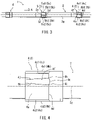
- the circular saw blade 1 may have tips 24 and 25 each having a groove 24f or 25f as illustrated in FIG 8 .
- the grooves 24f and 25f have a U-shaped configuration in a front view and connect first groove ends 24h and 25h and second groove ends 24i and 25i at the cutting edges 24d and 25d, in a circular arc manner.
- the tips 24 and 25 have other constitutional parts similar to tips 4 and 5. These parts shall be denoted by the same reference numerals as those of the tips 4 and 5, and will not be described in detail.
- V-grooves grooves 4f and 5f formed in a V-shape when viewed from the front
- U-grooves grooves 4f and 5f formed in a V-shape when viewed from the front
- V-grooves grooves 4f and 5f formed in a V-shape when viewed from the front
- U-grooves grooves 24f and 25f formed in the U-shape when viewed from the front
- a circular saw blade 1 having various tips 4 and 5 was prepared for experiments.
- An outer diameter of the circular saw blade 1 was 285 mm
- the thickness of the base metal 2 was 0.8 mm
- the blade thickness of the tips 4 and 5 was 1.0 mm
- the number of teeth was 60.
- a round rod made of S10C (Carbon steel for machine structure) having a diameter of 50 mm was prepared as a workpiece. Processing conditions were set for three types of feed speed: 0.05 mm/tooth, 0.07 mm/tooth, and 0.08 mm/tooth, while the rotational speed was set to 187 rpm. As illustrated in FIG. 9 , four types of grooves at the tips 4 and 5 were prepared. The conditions of the cutting chips and the cut surfaces were compared.
- the workpiece was cut using the circular saw blade 1 with the tips having a U-shaped groove type , the groove having a width of 0.23 mm and a depth of 0.16 mm.
- About 20% of the entire cutting chips were completely split into two cutting chips 6 and 7 at the feed speed of 0.05 mm/tooth, as illustrated in FIG. 7 .
- About 80% of the entire cutting chips 6 and 7 were connected with a separation streak part.
- the cut surfaces were in satisfactory condition without surface scratches.
- 100% of the entire cutting chips 6 and 7 were connected with a separation streak part.
- the cut surfaces were in satisfactory condition without surface scratches.
- At the feed speed of 0.08 mm/tooth 100% of the entire cutting chips 6 and 7 were connected with a separation streak part.
- the cut surfaces were in satisfactory condition without surface scratches.
- the workpiece was cut using the circular saw blade 1 with the tips having a V-shaped groove type, the groove having a width of 0.22 mm and a groove depth of 0.08 mm.
- 100% of the entire cutting chips 6 and 7 were connected with a separation streak part.
- the cut surface were in satisfactory condition without surface scratches.
- 100% of the entire cutting chips 6 and 7 were connected without a separation streak part.
- the surface scratches were formed on the cut surface, due to the cutting chips. Since surface scratches were developed at a feed speed of 0.07 mm/tooth, the experiment was not carried out at a feed speed of 0.08 mm/tooth.
- the workpiece was cut using the circular saw blade 1 with tips having a V-shaped groove type, the groove having a width of 0.24 mm and a depth of 0.10 mm.
- About 50% of the entire cutting chips were completely split into two cutting chips 6 and 7 at a feed speed of 0.05 mm/tooth.
- About 50% of the entire cutting chips 6 and 7 were connected with a separation streak part.
- the cut surfaces were in satisfactory condition without surface scratches.
- At a feed speed of 0.07 mm/tooth about 10% of the entire cutting chips were completely split into two cutting chips 6 and 7.
- About 90% of the entire cutting chips 6 and 7 were connected with a separation streak part.
- the cut surfaces were in satisfactory condition without surface scratches.
- At a feed speed of 0.08 mm/tooth 100% of the entire cutting chips 6 and 7 were connected without a separation streak part. Surface scratches developed on the cut surfaces due to the cutting chips.
- the workpiece was cut using the circular saw blade 1 with tips having a V-shaped groove type, the groove having a width of 0.26 mm and a depth of 0.12 mm.
- About 90% of the entire cutting chips were completely split into two cutting chips 6 and 7, at a feed speed of 0.05 mm/tooth.
- About 10% of the entire cutting chips 6 and 7 were connected with a separation streak part.
- the cut surfaces were in satisfactory condition without surface scratches.
- At a speed of 0.07 mm/tooth about 50% of the entire cutting chips were completely split into two cutting chips 6 and 7.
- About 50% of the entire cutting chips 6 and 7 were connected with a separation streak part.
- the cut surfaces were in satisfactory condition without surface scratches.
- the wear conditions of the tips were evaluated after cutting the workpiece with circular saw blades 1 equipped with tips having either a U-groove or V-groove.
- circular saw blades 1 with various tips 4 and 5 were prepared.
- the outer diameter of each circular saw blade 1 was 285 mm
- the thickness of the base metal 2 was 0.8 mm
- the blade thickness of the tips 4 and 5 was 1.0 mm.
- the tips having the U-groove and the V-groove were attached to two teeth out of 60 teeth, respectively.
- a round rod made of SUJ2 (High Carbon Steel) having a diameter of 30 mm was prepared as a workpiece. Cutting was carried out 100 times (corresponding to 3,000 cuts for 60 teeth), setting the rotational speed to 105 rpm and the feed speed 0.05 mm/tooth as a processing condition.
- the wear width in the circumferential direction at the center of the cutting edge on the flank was 79 ⁇ m, while the wear width in the circumferential direction at the groove end of the flank was 140 ⁇ m.
- the wear width in the circumferential direction at the center of the cutting edge of the flank was 83 ⁇ m, while the wear width in the circumferential direction at the groove end of the flank was 134 ⁇ m.
- a retraction amount of the groove end of the U-groove in the thickness direction of the cutting edge was 33 ⁇ m.
- a retraction amount of the groove end of the V-groove in the thickness direction on the cutting edge was 16 ⁇ m. Therefore, it is evident that the groove end of the V-groove is barely worn, compared to the groove end of the U-groove.
- the groove width of the groove is widened due to wear at the end of the groove. Expansion of the groove width was equal on the right and left sides.
- the retraction amount of the groove end of the U-groove in the thickness direction of the cutting edge is about twice as large as the retraction amount of the groove end of the V-groove in the thickness direction of the cutting edge.
- Chamfer-like chippings (wear) were observed at the corners of the U-groove.
- the chamfers 4c and 5c apply a load on the cutting chips in the side face direction and the load is transmitted vertically on the side face of the U-groove.
- the load applied by the chamfers 4c and 5c in the side face direction is dispersed in a radial direction by the beveled surfaces 4j and 4k, similar to the chamfers 4c and 5c.
- the load applied to the beveled surfaces 4j and 4k may be reduced and the wear at the V-groove may be less than the wear at U-groove.
- the angle of the U-groove with respect to the cutting edge is greater than that of the V-groove, it is believed that corner chipping may more likely to occur with the U-groove.
- the expansion speed of the groove width due to the wear of the U-groove is faster than that of the V-groove.
- the cutting edge is divided into two regions by the groove, and both of the regions will become shorter because of the expansion of the groove width. It is believed that chipping is more likely to occur when the region is shorter, because its length cannot withstand the cutting impact.
- the groove width is structured to be 0.20 mm to 0.30 mm. Therefore, the groove width is relatively short as compared the blade thickness. Consequently, the effective length of the cutting edges 4d and 5d is long so that a chipping resistance of the tips will be relatively high. Further, with the configuration including grooves having a predetermined length, the cutting chips may be easily split. In this way, it is possible to prevent the cut surface of the workpiece from getting scratched by the cutting chips.
- the grooves 4f, 5f on the cutting edges 4d, 5d include a pair of a first groove end 4h and a second groove end 4i, and a pair of linear beveled surfaces 4j and 4k extending from the first groove end 4h and the second groove end 4i, and curved groove bottoms 4m, 5m configured to connect the beveled surfaces 4j and 4k.
- the beveled surfaces 4j and 4k have an acute angle at the groove end angle ⁇ with respect to the flanks 4a, 5a oriented outward in the radial direction of the tips 4. In this configuration, the rigidity at the corners between the cutting edges 4d, 5d and the beveled surfaces 4j, 4k is increased so that chipping may be reduced.
- the grooves 24f, 25f may also achieve a similar effect as grooves 4f, 5f.
- the tips includes tips 4 (first tips) with a groove located closer to one side with respect to the center position in the thickness direction of the cutting edges 4d and 5d, and tips 5 (second tips) with a groove located closer to the other side.
- the tips 4 and 5 may be alternately arranged in the circumferential direction. In this configuration, it is possible to prevent the load in the lateral direction from de-centering during cutting. Further, since the cutting chips are split, the cutting chips are properly discharged so that an influence of the cutting chips on the cut surfaces of the workpiece may be reduced.
Landscapes
- Engineering & Computer Science (AREA)
- Mechanical Engineering (AREA)
- Life Sciences & Earth Sciences (AREA)
- Wood Science & Technology (AREA)
- Forests & Forestry (AREA)
- Milling Processes (AREA)
- Finish Polishing, Edge Sharpening, And Grinding By Specific Grinding Devices (AREA)
- Drilling Tools (AREA)
- Polishing Bodies And Polishing Tools (AREA)
Claims (3)
- Kreissägeblatt (1) mit Spitzen, umfassend:ein scheibenförmiges Basismetall (2) undSpitzen (4, 5), die mit dem Basismetall (2) verbunden sind, so dass sie von einem äußeren Umfang des Basismetalls (2) in eine radiale Richtung vorragen, wobei:ein Außendurchmesser des Kreissägeblatts (1) 280 mm bis 500 mm beträgt,eine Blattdicke der Spitze (4, 5) 0,8 mm bis 1,1 mm beträgt undjede der Spitzen (4, 5) Folgendes aufweist:eine Flanke (4a, 5a), die in der radialen Richtung nach außen weist,eine Seitenfläche (4b, 5b), die an einem von beiden Enden der Flanke (4a, 5a) in einer Dickenrichtung positioniert ist, undeine Abschrägung (4c, 5c), die zwischen der Flanke (4a, 5a) und der Seitenfläche (4b, 5b) ausgebildet ist, wobei die Abschrägung (4c, 5c) einen Abschrägungswinkel (θ) bezüglich der Flanke (4a, 5a) hat,eine Schneidkante (4d, 5d), die an einem Ende der Flanke (4a, 5a) in einer Umfangsrichtung positioniert ist, wobei die Schneidkante (4d, 5d) zum Schneiden eines Werkstücks ausgestaltet ist, undeine Nut (4f, 5f), die an der Flanke (4a, 5a) ausgebildet ist, um sich von der Schneidkante (4d, 5d) in die Umfangsrichtung zu erstrecken, wobei die Nut (4f, 5f) eine Breite (X) von 0,20 mm bis 0,30 mm und eine Tiefe (Z) von 0,10 mm bis 0,15 mm hat,wobeidie Nut (4f, 5f) ein Paar abgefaster Flächen (4j, 4k), die bezüglich der Flanke (4a, 5a) geneigt sind, und einen gebogenen Nutboden (4m) aufweist, der zum Verbinden des Paars abgefaster Flächen (4j, 4k) ausgestaltet ist.
- Kreissägeblatt mit Spitzen nach Anspruch 1, wobei:die Nut (4f, 5f) ein Paar Nutenenden (4h, 4i, 5h, 5i) an der Schneidkante (4d, 5d) aufweist, wobei sich das Paar gerader abgefaster Flächen (4j, 4k) von jedem der Nutenenden (4h, 4i, 5h, 5i) erstrecken und der gebogene Nutboden (4m) zum Verbinden des Paars abgefaster Flächen (4j, 4k) ausgestaltet ist, undspitze Nutenendenwinkel zwischen den abgefasten Flächen (4j, 4k) und der Flanke (4a, 5a) gebildet sind.
- Kreissägeblatt (1) mit Spitzen, umfassend:ein scheibenförmiges Basismetall (2) undSpitzen (24, 25), die mit dem Basismetall (2) verbunden sind, so dass sie von einem äußeren Umfang des Basismetalls (2) in eine radiale Richtung vorragen, wobei:ein Außendurchmesser des Kreissägeblatts (1) 280 mm bis 500 mm beträgt,eine Blattdicke der Spitze (24, 25) 0,8 mm bis 1,1 mm beträgt undjede der Spitzen (24, 25) Folgendes aufweist:eine Flanke (4a, 5a), die in der radialen Richtung nach außen weist,eine Seitenfläche (4b, 5b), die an einem von beiden Enden der Flanke (4a, 5a) in einer Dickenrichtung positioniert ist, undeine Abschrägung (4c, 5c), die zwischen der Flanke (4a, 5a) und der Seitenfläche (4b, 5b) ausgebildet ist, wobei die Abschrägung (4c, 5c) einen Abschrägungswinkel (θ) bezüglich der Flanke (4a, 5a) hat,eine Schneidkante (24d, 25d), die an einem Ende der Flanke (4a, 5a) in einer Umfangsrichtung positioniert ist, wobei die Schneidkante (24d, 25d) zum Schneiden eines Werkstücks ausgestaltet ist, undeine Nut (24f, 25f), die an der Flanke (4a, 5a) ausgebildet ist, um sich von der Schneidkante (24d, 25d) in die Umfangsrichtung zu erstrecken, wobei die Nut (24f, 25f) eine Breite von 0,20 mm bis 0,30 mm hat, wobeijede der Nuten (24f, 25f) eine Konfiguration hat, um ein erstes Nutenende (24h, 25h) an der Schneidkante (24d, 25d) und ein zweites Nutenende (24i, 25i) an der Schneidkante (24d, 25d) kreisbogenförmig zu verbinden.
Applications Claiming Priority (2)
| Application Number | Priority Date | Filing Date | Title |
|---|---|---|---|
| JP2016204381 | 2016-10-18 | ||
| PCT/JP2017/028542 WO2018074038A1 (ja) | 2016-10-18 | 2017-08-07 | チップ付き丸鋸刃 |
Publications (3)
| Publication Number | Publication Date |
|---|---|
| EP3530392A1 EP3530392A1 (de) | 2019-08-28 |
| EP3530392A4 EP3530392A4 (de) | 2020-10-28 |
| EP3530392B1 true EP3530392B1 (de) | 2022-06-15 |
Family
ID=62019260
Family Applications (1)
| Application Number | Title | Priority Date | Filing Date |
|---|---|---|---|
| EP17862334.4A Active EP3530392B1 (de) | 2016-10-18 | 2017-08-07 | Kreissägeblätter mit mit spitzen |
Country Status (6)
| Country | Link |
|---|---|
| US (1) | US10960476B2 (de) |
| EP (1) | EP3530392B1 (de) |
| JP (1) | JP6845250B2 (de) |
| CN (1) | CN109963677B (de) |
| TW (1) | TWI753006B (de) |
| WO (1) | WO2018074038A1 (de) |
Families Citing this family (10)
| Publication number | Priority date | Publication date | Assignee | Title |
|---|---|---|---|---|
| USD925626S1 (en) * | 2019-02-26 | 2021-07-20 | The Charles Machine Works, Inc. | Microtrencher blade |
| USD925628S1 (en) * | 2019-02-26 | 2021-07-20 | The Charles Machine Works, Inc. | Microtrencher blade |
| USD925627S1 (en) * | 2019-02-26 | 2021-07-20 | The Charles Machine Works, Inc. | Microtrencher blade |
| CA3136572A1 (en) * | 2019-04-12 | 2020-10-15 | The M.K. Morse Company | Improved circular saw |
| MX2022004096A (es) * | 2019-10-10 | 2022-07-11 | The M K Morse Company | Metodo para revestir los dientes de una herramienta de corte. |
| CN114667195B (zh) * | 2019-12-19 | 2023-11-14 | 兼房株式会社 | 圆锯片 |
| WO2022072779A1 (en) * | 2020-10-02 | 2022-04-07 | Gcp Applied Technologies Inc. | Early strength slag-based cementitious binder |
| EP4331764A4 (de) * | 2021-04-27 | 2025-04-23 | Kanefusa Kabushiki Kaisha | Kreissägeblatt mit spitze |
| USD1040197S1 (en) | 2021-07-16 | 2024-08-27 | The Charles Machine Works, Inc. | Microtrencher blade |
| USD1032318S1 (en) | 2022-03-17 | 2024-06-25 | The Charles Machine Works, Inc. | Tooth for use with a microtrenching blade |
Family Cites Families (26)
| Publication number | Priority date | Publication date | Assignee | Title |
|---|---|---|---|---|
| DE3711228A1 (de) * | 1987-04-03 | 1988-10-20 | Wagner Maschf Gustav | Schneidezahn sowie mit solchen schneidezaehnen versehene metallsaegen, insbesondere kreissaegeblaetter |
| JPH05220614A (ja) * | 1992-02-06 | 1993-08-31 | Hitachi Tool Eng Ltd | メタルソー |
| CN1094083C (zh) * | 1994-02-23 | 2002-11-13 | 松下电工株式会社 | 锯片 |
| JP3407831B2 (ja) * | 1994-11-23 | 2003-05-19 | 株式会社谷テック | 回転鋸 |
| JPH08187702A (ja) * | 1995-01-13 | 1996-07-23 | Kanefusa Kk | 低騒音丸鋸 |
| JPH106133A (ja) * | 1996-06-17 | 1998-01-13 | Nakajima Kokan Kk | 丸 鋸 |
| JP3203420B2 (ja) * | 1998-05-29 | 2001-08-27 | 兼房株式会社 | 硬質チップ付丸鋸 |
| JP2001347412A (ja) | 2000-04-06 | 2001-12-18 | Yutaka Seimitsu Kogyo Ltd | 正面カッタおよびカッタ用ブレード |
| JP3505476B2 (ja) * | 2000-06-06 | 2004-03-08 | 株式会社津根ワグナーカーバイト | 丸 鋸 |
| US10105773B1 (en) * | 2004-09-02 | 2018-10-23 | Robert Bosch Tool Corporation | Box joint blade system |
| US20070163416A1 (en) * | 2006-01-13 | 2007-07-19 | The M. K. Morse Company | Circular saw blade |
| JP4420464B2 (ja) * | 2006-01-30 | 2010-02-24 | 株式会社谷テック | チップソー |
| CN101758521B (zh) * | 2010-01-07 | 2012-05-09 | 宫电高周波设备(上海)有限公司 | 镶刃锯片 |
| DE102010016153A1 (de) * | 2010-03-26 | 2011-09-29 | Arno Friedrichs | Hydrodynamisch geführtes Kreissägeblatt |
| CN202239947U (zh) * | 2011-08-09 | 2012-05-30 | 杭州和源精密工具有限公司 | 新型锯齿刀头锯片 |
| JP2013154415A (ja) * | 2012-01-27 | 2013-08-15 | Allied Material Corp | サーキュラーソーおよび切削加工法 |
| EP2855060A2 (de) * | 2012-05-24 | 2015-04-08 | Gershon System Ltd. | Verfahren für den entwurf einer schneidkante eines schneidwerkzeugs, schneidwerkzeuge damit und schneidelement mit mehreren solchen teilen |
| US9227342B2 (en) * | 2012-12-31 | 2016-01-05 | Saint-Gobain Abrasives, Inc | Abrasive article having abrasive segments with shaped gullet walls |
| JP6339764B2 (ja) | 2013-02-25 | 2018-06-06 | 兼房株式会社 | 丸鋸 |
| US9789552B2 (en) * | 2013-06-27 | 2017-10-17 | Irwin Industrial Tool Company | Saw blade and saw blade tooth construction |
| CN104353898B (zh) * | 2014-09-30 | 2016-08-31 | 杭州和源精密工具有限公司 | 一种切割不锈钢冷锯的制备方法及其锯片 |
| JP2017001099A (ja) * | 2015-06-04 | 2017-01-05 | 兼房株式会社 | チップ付き丸鋸刃 |
| JP6577293B2 (ja) * | 2015-08-24 | 2019-09-18 | 兼房株式会社 | チップ付き丸鋸刃 |
| US10279407B2 (en) * | 2015-10-30 | 2019-05-07 | Black & Decker Inc. | Circular saw blades |
| JP6583921B2 (ja) * | 2016-06-30 | 2019-10-02 | 株式会社谷テック | コンポジット材用チップソー |
| CN107052453A (zh) * | 2017-05-04 | 2017-08-18 | 叶向前 | 一种交替斜削齿圆锯片 |
-
2017
- 2017-08-07 EP EP17862334.4A patent/EP3530392B1/de active Active
- 2017-08-07 JP JP2018546159A patent/JP6845250B2/ja active Active
- 2017-08-07 WO PCT/JP2017/028542 patent/WO2018074038A1/ja not_active Ceased
- 2017-08-07 CN CN201780064707.0A patent/CN109963677B/zh active Active
- 2017-08-07 US US16/343,021 patent/US10960476B2/en active Active
- 2017-09-06 TW TW106130424A patent/TWI753006B/zh active
Also Published As
| Publication number | Publication date |
|---|---|
| WO2018074038A1 (ja) | 2018-04-26 |
| US10960476B2 (en) | 2021-03-30 |
| EP3530392A4 (de) | 2020-10-28 |
| CN109963677B (zh) | 2021-09-07 |
| TW201822925A (zh) | 2018-07-01 |
| US20200047267A1 (en) | 2020-02-13 |
| JPWO2018074038A1 (ja) | 2019-08-08 |
| TWI753006B (zh) | 2022-01-21 |
| CN109963677A (zh) | 2019-07-02 |
| EP3530392A1 (de) | 2019-08-28 |
| JP6845250B2 (ja) | 2021-03-17 |
Similar Documents
| Publication | Publication Date | Title |
|---|---|---|
| EP3530392B1 (de) | Kreissägeblätter mit mit spitzen | |
| KR20020077909A (ko) | 커팅인써트 및 해당 밀링커터 | |
| US6939092B2 (en) | Sheet metal hole cutter | |
| JP4754260B2 (ja) | 丸鋸 | |
| JP2008540147A (ja) | 工具用、特にフライス用の切削インサート | |
| KR20190131409A (ko) | 밀링 공구 | |
| JPH10263911A (ja) | 深溝加工用カッター | |
| JP4142892B2 (ja) | 刃先交換式回転工具 | |
| JP2017001099A (ja) | チップ付き丸鋸刃 | |
| JPH09225724A (ja) | フライス用チップ | |
| US9895757B2 (en) | Reamer | |
| JP3197520B2 (ja) | ダイヤモンドチップソー | |
| JP2009214250A (ja) | 金属切断用丸鋸 | |
| CN216096763U (zh) | 带刀头的圆锯片 | |
| WO2001098010A1 (en) | Circular saw for metal cutting | |
| JP2000254822A (ja) | チップソー | |
| JP4853958B2 (ja) | チップソー | |
| JP2012056067A (ja) | 金属切断用丸鋸 | |
| US20240217010A1 (en) | Tipped circular saw blade | |
| JP4227760B2 (ja) | 金属切断用丸鋸 | |
| JP3187689U (ja) | 丸鋸刃 | |
| JP2015145053A (ja) | チップソー及びチップの組み合わせ | |
| JP7433639B2 (ja) | 金属切断用丸鋸 | |
| JP3864024B2 (ja) | クリスマスカッタ | |
| JP4309526B2 (ja) | 溝入れ用スローアウェイチップ及び溝入れ加工方法 |
Legal Events
| Date | Code | Title | Description |
|---|---|---|---|
| STAA | Information on the status of an ep patent application or granted ep patent |
Free format text: STATUS: THE INTERNATIONAL PUBLICATION HAS BEEN MADE |
|
| PUAI | Public reference made under article 153(3) epc to a published international application that has entered the european phase |
Free format text: ORIGINAL CODE: 0009012 |
|
| STAA | Information on the status of an ep patent application or granted ep patent |
Free format text: STATUS: REQUEST FOR EXAMINATION WAS MADE |
|
| 17P | Request for examination filed |
Effective date: 20190425 |
|
| AK | Designated contracting states |
Kind code of ref document: A1 Designated state(s): AL AT BE BG CH CY CZ DE DK EE ES FI FR GB GR HR HU IE IS IT LI LT LU LV MC MK MT NL NO PL PT RO RS SE SI SK SM TR |
|
| AX | Request for extension of the european patent |
Extension state: BA ME |
|
| DAV | Request for validation of the european patent (deleted) | ||
| DAX | Request for extension of the european patent (deleted) | ||
| A4 | Supplementary search report drawn up and despatched |
Effective date: 20200925 |
|
| RIC1 | Information provided on ipc code assigned before grant |
Ipc: B27B 33/02 20060101ALI20200921BHEP Ipc: B23D 61/04 20060101AFI20200921BHEP |
|
| GRAP | Despatch of communication of intention to grant a patent |
Free format text: ORIGINAL CODE: EPIDOSNIGR1 |
|
| STAA | Information on the status of an ep patent application or granted ep patent |
Free format text: STATUS: GRANT OF PATENT IS INTENDED |
|
| INTG | Intention to grant announced |
Effective date: 20220110 |
|
| GRAS | Grant fee paid |
Free format text: ORIGINAL CODE: EPIDOSNIGR3 |
|
| GRAA | (expected) grant |
Free format text: ORIGINAL CODE: 0009210 |
|
| STAA | Information on the status of an ep patent application or granted ep patent |
Free format text: STATUS: THE PATENT HAS BEEN GRANTED |
|
| AK | Designated contracting states |
Kind code of ref document: B1 Designated state(s): AL AT BE BG CH CY CZ DE DK EE ES FI FR GB GR HR HU IE IS IT LI LT LU LV MC MK MT NL NO PL PT RO RS SE SI SK SM TR |
|
| REG | Reference to a national code |
Ref country code: CH Ref legal event code: EP Ref country code: GB Ref legal event code: FG4D |
|
| REG | Reference to a national code |
Ref country code: IE Ref legal event code: FG4D |
|
| REG | Reference to a national code |
Ref country code: DE Ref legal event code: R096 Ref document number: 602017058626 Country of ref document: DE |
|
| REG | Reference to a national code |
Ref country code: AT Ref legal event code: REF Ref document number: 1498053 Country of ref document: AT Kind code of ref document: T Effective date: 20220715 |
|
| REG | Reference to a national code |
Ref country code: LT Ref legal event code: MG9D |
|
| REG | Reference to a national code |
Ref country code: NL Ref legal event code: MP Effective date: 20220615 |
|
| PG25 | Lapsed in a contracting state [announced via postgrant information from national office to epo] |
Ref country code: SE Free format text: LAPSE BECAUSE OF FAILURE TO SUBMIT A TRANSLATION OF THE DESCRIPTION OR TO PAY THE FEE WITHIN THE PRESCRIBED TIME-LIMIT Effective date: 20220615 Ref country code: NO Free format text: LAPSE BECAUSE OF FAILURE TO SUBMIT A TRANSLATION OF THE DESCRIPTION OR TO PAY THE FEE WITHIN THE PRESCRIBED TIME-LIMIT Effective date: 20220915 Ref country code: LT Free format text: LAPSE BECAUSE OF FAILURE TO SUBMIT A TRANSLATION OF THE DESCRIPTION OR TO PAY THE FEE WITHIN THE PRESCRIBED TIME-LIMIT Effective date: 20220615 Ref country code: HR Free format text: LAPSE BECAUSE OF FAILURE TO SUBMIT A TRANSLATION OF THE DESCRIPTION OR TO PAY THE FEE WITHIN THE PRESCRIBED TIME-LIMIT Effective date: 20220615 Ref country code: GR Free format text: LAPSE BECAUSE OF FAILURE TO SUBMIT A TRANSLATION OF THE DESCRIPTION OR TO PAY THE FEE WITHIN THE PRESCRIBED TIME-LIMIT Effective date: 20220916 Ref country code: FI Free format text: LAPSE BECAUSE OF FAILURE TO SUBMIT A TRANSLATION OF THE DESCRIPTION OR TO PAY THE FEE WITHIN THE PRESCRIBED TIME-LIMIT Effective date: 20220615 Ref country code: BG Free format text: LAPSE BECAUSE OF FAILURE TO SUBMIT A TRANSLATION OF THE DESCRIPTION OR TO PAY THE FEE WITHIN THE PRESCRIBED TIME-LIMIT Effective date: 20220915 |
|
| REG | Reference to a national code |
Ref country code: AT Ref legal event code: MK05 Ref document number: 1498053 Country of ref document: AT Kind code of ref document: T Effective date: 20220615 |
|
| PG25 | Lapsed in a contracting state [announced via postgrant information from national office to epo] |
Ref country code: RS Free format text: LAPSE BECAUSE OF FAILURE TO SUBMIT A TRANSLATION OF THE DESCRIPTION OR TO PAY THE FEE WITHIN THE PRESCRIBED TIME-LIMIT Effective date: 20220615 Ref country code: LV Free format text: LAPSE BECAUSE OF FAILURE TO SUBMIT A TRANSLATION OF THE DESCRIPTION OR TO PAY THE FEE WITHIN THE PRESCRIBED TIME-LIMIT Effective date: 20220615 |
|
| PG25 | Lapsed in a contracting state [announced via postgrant information from national office to epo] |
Ref country code: NL Free format text: LAPSE BECAUSE OF FAILURE TO SUBMIT A TRANSLATION OF THE DESCRIPTION OR TO PAY THE FEE WITHIN THE PRESCRIBED TIME-LIMIT Effective date: 20220615 |
|
| PG25 | Lapsed in a contracting state [announced via postgrant information from national office to epo] |
Ref country code: SM Free format text: LAPSE BECAUSE OF FAILURE TO SUBMIT A TRANSLATION OF THE DESCRIPTION OR TO PAY THE FEE WITHIN THE PRESCRIBED TIME-LIMIT Effective date: 20220615 Ref country code: SK Free format text: LAPSE BECAUSE OF FAILURE TO SUBMIT A TRANSLATION OF THE DESCRIPTION OR TO PAY THE FEE WITHIN THE PRESCRIBED TIME-LIMIT Effective date: 20220615 Ref country code: RO Free format text: LAPSE BECAUSE OF FAILURE TO SUBMIT A TRANSLATION OF THE DESCRIPTION OR TO PAY THE FEE WITHIN THE PRESCRIBED TIME-LIMIT Effective date: 20220615 Ref country code: PT Free format text: LAPSE BECAUSE OF FAILURE TO SUBMIT A TRANSLATION OF THE DESCRIPTION OR TO PAY THE FEE WITHIN THE PRESCRIBED TIME-LIMIT Effective date: 20221017 Ref country code: ES Free format text: LAPSE BECAUSE OF FAILURE TO SUBMIT A TRANSLATION OF THE DESCRIPTION OR TO PAY THE FEE WITHIN THE PRESCRIBED TIME-LIMIT Effective date: 20220615 Ref country code: EE Free format text: LAPSE BECAUSE OF FAILURE TO SUBMIT A TRANSLATION OF THE DESCRIPTION OR TO PAY THE FEE WITHIN THE PRESCRIBED TIME-LIMIT Effective date: 20220615 Ref country code: AT Free format text: LAPSE BECAUSE OF FAILURE TO SUBMIT A TRANSLATION OF THE DESCRIPTION OR TO PAY THE FEE WITHIN THE PRESCRIBED TIME-LIMIT Effective date: 20220615 |
|
| PG25 | Lapsed in a contracting state [announced via postgrant information from national office to epo] |
Ref country code: PL Free format text: LAPSE BECAUSE OF FAILURE TO SUBMIT A TRANSLATION OF THE DESCRIPTION OR TO PAY THE FEE WITHIN THE PRESCRIBED TIME-LIMIT Effective date: 20220615 Ref country code: IS Free format text: LAPSE BECAUSE OF FAILURE TO SUBMIT A TRANSLATION OF THE DESCRIPTION OR TO PAY THE FEE WITHIN THE PRESCRIBED TIME-LIMIT Effective date: 20221015 |
|
| REG | Reference to a national code |
Ref country code: DE Ref legal event code: R097 Ref document number: 602017058626 Country of ref document: DE |
|
| PG25 | Lapsed in a contracting state [announced via postgrant information from national office to epo] |
Ref country code: MC Free format text: LAPSE BECAUSE OF FAILURE TO SUBMIT A TRANSLATION OF THE DESCRIPTION OR TO PAY THE FEE WITHIN THE PRESCRIBED TIME-LIMIT Effective date: 20220615 Ref country code: AL Free format text: LAPSE BECAUSE OF FAILURE TO SUBMIT A TRANSLATION OF THE DESCRIPTION OR TO PAY THE FEE WITHIN THE PRESCRIBED TIME-LIMIT Effective date: 20220615 |
|
| REG | Reference to a national code |
Ref country code: CH Ref legal event code: PL |
|
| PLBE | No opposition filed within time limit |
Free format text: ORIGINAL CODE: 0009261 |
|
| STAA | Information on the status of an ep patent application or granted ep patent |
Free format text: STATUS: NO OPPOSITION FILED WITHIN TIME LIMIT |
|
| PG25 | Lapsed in a contracting state [announced via postgrant information from national office to epo] |
Ref country code: LU Free format text: LAPSE BECAUSE OF NON-PAYMENT OF DUE FEES Effective date: 20220807 Ref country code: LI Free format text: LAPSE BECAUSE OF NON-PAYMENT OF DUE FEES Effective date: 20220831 Ref country code: DK Free format text: LAPSE BECAUSE OF FAILURE TO SUBMIT A TRANSLATION OF THE DESCRIPTION OR TO PAY THE FEE WITHIN THE PRESCRIBED TIME-LIMIT Effective date: 20220615 Ref country code: CH Free format text: LAPSE BECAUSE OF NON-PAYMENT OF DUE FEES Effective date: 20220831 |
|
| REG | Reference to a national code |
Ref country code: BE Ref legal event code: MM Effective date: 20220831 |
|
| 26N | No opposition filed |
Effective date: 20230316 |
|
| PG25 | Lapsed in a contracting state [announced via postgrant information from national office to epo] |
Ref country code: SI Free format text: LAPSE BECAUSE OF FAILURE TO SUBMIT A TRANSLATION OF THE DESCRIPTION OR TO PAY THE FEE WITHIN THE PRESCRIBED TIME-LIMIT Effective date: 20220615 |
|
| PG25 | Lapsed in a contracting state [announced via postgrant information from national office to epo] |
Ref country code: IE Free format text: LAPSE BECAUSE OF NON-PAYMENT OF DUE FEES Effective date: 20220807 |
|
| PG25 | Lapsed in a contracting state [announced via postgrant information from national office to epo] |
Ref country code: BE Free format text: LAPSE BECAUSE OF NON-PAYMENT OF DUE FEES Effective date: 20220831 |
|
| PG25 | Lapsed in a contracting state [announced via postgrant information from national office to epo] |
Ref country code: IT Free format text: LAPSE BECAUSE OF FAILURE TO SUBMIT A TRANSLATION OF THE DESCRIPTION OR TO PAY THE FEE WITHIN THE PRESCRIBED TIME-LIMIT Effective date: 20220615 |
|
| PG25 | Lapsed in a contracting state [announced via postgrant information from national office to epo] |
Ref country code: HU Free format text: LAPSE BECAUSE OF FAILURE TO SUBMIT A TRANSLATION OF THE DESCRIPTION OR TO PAY THE FEE WITHIN THE PRESCRIBED TIME-LIMIT; INVALID AB INITIO Effective date: 20170807 |
|
| PG25 | Lapsed in a contracting state [announced via postgrant information from national office to epo] |
Ref country code: CY Free format text: LAPSE BECAUSE OF FAILURE TO SUBMIT A TRANSLATION OF THE DESCRIPTION OR TO PAY THE FEE WITHIN THE PRESCRIBED TIME-LIMIT Effective date: 20220615 |
|
| PG25 | Lapsed in a contracting state [announced via postgrant information from national office to epo] |
Ref country code: MK Free format text: LAPSE BECAUSE OF FAILURE TO SUBMIT A TRANSLATION OF THE DESCRIPTION OR TO PAY THE FEE WITHIN THE PRESCRIBED TIME-LIMIT Effective date: 20220615 |
|
| PG25 | Lapsed in a contracting state [announced via postgrant information from national office to epo] |
Ref country code: MT Free format text: LAPSE BECAUSE OF FAILURE TO SUBMIT A TRANSLATION OF THE DESCRIPTION OR TO PAY THE FEE WITHIN THE PRESCRIBED TIME-LIMIT Effective date: 20220615 |
|
| PG25 | Lapsed in a contracting state [announced via postgrant information from national office to epo] |
Ref country code: BG Free format text: LAPSE BECAUSE OF FAILURE TO SUBMIT A TRANSLATION OF THE DESCRIPTION OR TO PAY THE FEE WITHIN THE PRESCRIBED TIME-LIMIT Effective date: 20220615 |
|
| PG25 | Lapsed in a contracting state [announced via postgrant information from national office to epo] |
Ref country code: BG Free format text: LAPSE BECAUSE OF FAILURE TO SUBMIT A TRANSLATION OF THE DESCRIPTION OR TO PAY THE FEE WITHIN THE PRESCRIBED TIME-LIMIT Effective date: 20220615 |
|
| PGFP | Annual fee paid to national office [announced via postgrant information from national office to epo] |
Ref country code: DE Payment date: 20250820 Year of fee payment: 9 |
|
| PGFP | Annual fee paid to national office [announced via postgrant information from national office to epo] |
Ref country code: GB Payment date: 20250820 Year of fee payment: 9 |
|
| PGFP | Annual fee paid to national office [announced via postgrant information from national office to epo] |
Ref country code: FR Payment date: 20250828 Year of fee payment: 9 |
|
| PGFP | Annual fee paid to national office [announced via postgrant information from national office to epo] |
Ref country code: CZ Payment date: 20250725 Year of fee payment: 9 |
|
| PG25 | Lapsed in a contracting state [announced via postgrant information from national office to epo] |
Ref country code: TR Free format text: LAPSE BECAUSE OF FAILURE TO SUBMIT A TRANSLATION OF THE DESCRIPTION OR TO PAY THE FEE WITHIN THE PRESCRIBED TIME-LIMIT Effective date: 20220615 |