EP3268253B1 - Système de freinage hydraulique - Google Patents
Système de freinage hydraulique Download PDFInfo
- Publication number
- EP3268253B1 EP3268253B1 EP16704797.6A EP16704797A EP3268253B1 EP 3268253 B1 EP3268253 B1 EP 3268253B1 EP 16704797 A EP16704797 A EP 16704797A EP 3268253 B1 EP3268253 B1 EP 3268253B1
- Authority
- EP
- European Patent Office
- Prior art keywords
- valve
- line
- control
- brake
- wheel brake
- Prior art date
- Legal status (The legal status is an assumption and is not a legal conclusion. Google has not performed a legal analysis and makes no representation as to the accuracy of the status listed.)
- Active
Links
Images


Classifications
-
- B—PERFORMING OPERATIONS; TRANSPORTING
- B60—VEHICLES IN GENERAL
- B60T—VEHICLE BRAKE CONTROL SYSTEMS OR PARTS THEREOF; BRAKE CONTROL SYSTEMS OR PARTS THEREOF, IN GENERAL; ARRANGEMENT OF BRAKING ELEMENTS ON VEHICLES IN GENERAL; PORTABLE DEVICES FOR PREVENTING UNWANTED MOVEMENT OF VEHICLES; VEHICLE MODIFICATIONS TO FACILITATE COOLING OF BRAKES
- B60T8/00—Arrangements for adjusting wheel-braking force to meet varying vehicular or ground-surface conditions, e.g. limiting or varying distribution of braking force
- B60T8/32—Arrangements for adjusting wheel-braking force to meet varying vehicular or ground-surface conditions, e.g. limiting or varying distribution of braking force responsive to a speed condition, e.g. acceleration or deceleration
- B60T8/34—Arrangements for adjusting wheel-braking force to meet varying vehicular or ground-surface conditions, e.g. limiting or varying distribution of braking force responsive to a speed condition, e.g. acceleration or deceleration having a fluid pressure regulator responsive to a speed condition
- B60T8/48—Arrangements for adjusting wheel-braking force to meet varying vehicular or ground-surface conditions, e.g. limiting or varying distribution of braking force responsive to a speed condition, e.g. acceleration or deceleration having a fluid pressure regulator responsive to a speed condition connecting the brake actuator to an alternative or additional source of fluid pressure, e.g. traction control systems
- B60T8/4809—Traction control, stability control, using both the wheel brakes and other automatic braking systems
- B60T8/4827—Traction control, stability control, using both the wheel brakes and other automatic braking systems in hydraulic brake systems
-
- B—PERFORMING OPERATIONS; TRANSPORTING
- B60—VEHICLES IN GENERAL
- B60T—VEHICLE BRAKE CONTROL SYSTEMS OR PARTS THEREOF; BRAKE CONTROL SYSTEMS OR PARTS THEREOF, IN GENERAL; ARRANGEMENT OF BRAKING ELEMENTS ON VEHICLES IN GENERAL; PORTABLE DEVICES FOR PREVENTING UNWANTED MOVEMENT OF VEHICLES; VEHICLE MODIFICATIONS TO FACILITATE COOLING OF BRAKES
- B60T8/00—Arrangements for adjusting wheel-braking force to meet varying vehicular or ground-surface conditions, e.g. limiting or varying distribution of braking force
- B60T8/32—Arrangements for adjusting wheel-braking force to meet varying vehicular or ground-surface conditions, e.g. limiting or varying distribution of braking force responsive to a speed condition, e.g. acceleration or deceleration
- B60T8/34—Arrangements for adjusting wheel-braking force to meet varying vehicular or ground-surface conditions, e.g. limiting or varying distribution of braking force responsive to a speed condition, e.g. acceleration or deceleration having a fluid pressure regulator responsive to a speed condition
- B60T8/343—Systems characterised by their lay-out
- B60T8/344—Hydraulic systems
- B60T8/345—Hydraulic systems having more than one brake circuit per wheel
-
- B—PERFORMING OPERATIONS; TRANSPORTING
- B60—VEHICLES IN GENERAL
- B60T—VEHICLE BRAKE CONTROL SYSTEMS OR PARTS THEREOF; BRAKE CONTROL SYSTEMS OR PARTS THEREOF, IN GENERAL; ARRANGEMENT OF BRAKING ELEMENTS ON VEHICLES IN GENERAL; PORTABLE DEVICES FOR PREVENTING UNWANTED MOVEMENT OF VEHICLES; VEHICLE MODIFICATIONS TO FACILITATE COOLING OF BRAKES
- B60T8/00—Arrangements for adjusting wheel-braking force to meet varying vehicular or ground-surface conditions, e.g. limiting or varying distribution of braking force
- B60T8/32—Arrangements for adjusting wheel-braking force to meet varying vehicular or ground-surface conditions, e.g. limiting or varying distribution of braking force responsive to a speed condition, e.g. acceleration or deceleration
- B60T8/34—Arrangements for adjusting wheel-braking force to meet varying vehicular or ground-surface conditions, e.g. limiting or varying distribution of braking force responsive to a speed condition, e.g. acceleration or deceleration having a fluid pressure regulator responsive to a speed condition
- B60T8/36—Arrangements for adjusting wheel-braking force to meet varying vehicular or ground-surface conditions, e.g. limiting or varying distribution of braking force responsive to a speed condition, e.g. acceleration or deceleration having a fluid pressure regulator responsive to a speed condition including a pilot valve responding to an electromagnetic force
- B60T8/3615—Electromagnetic valves specially adapted for anti-lock brake and traction control systems
- B60T8/363—Electromagnetic valves specially adapted for anti-lock brake and traction control systems in hydraulic systems
- B60T8/3635—Electromagnetic valves specially adapted for anti-lock brake and traction control systems in hydraulic systems switching between more than two connections, e.g. 3/2-valves
-
- B—PERFORMING OPERATIONS; TRANSPORTING
- B60—VEHICLES IN GENERAL
- B60T—VEHICLE BRAKE CONTROL SYSTEMS OR PARTS THEREOF; BRAKE CONTROL SYSTEMS OR PARTS THEREOF, IN GENERAL; ARRANGEMENT OF BRAKING ELEMENTS ON VEHICLES IN GENERAL; PORTABLE DEVICES FOR PREVENTING UNWANTED MOVEMENT OF VEHICLES; VEHICLE MODIFICATIONS TO FACILITATE COOLING OF BRAKES
- B60T8/00—Arrangements for adjusting wheel-braking force to meet varying vehicular or ground-surface conditions, e.g. limiting or varying distribution of braking force
- B60T8/32—Arrangements for adjusting wheel-braking force to meet varying vehicular or ground-surface conditions, e.g. limiting or varying distribution of braking force responsive to a speed condition, e.g. acceleration or deceleration
- B60T8/34—Arrangements for adjusting wheel-braking force to meet varying vehicular or ground-surface conditions, e.g. limiting or varying distribution of braking force responsive to a speed condition, e.g. acceleration or deceleration having a fluid pressure regulator responsive to a speed condition
- B60T8/36—Arrangements for adjusting wheel-braking force to meet varying vehicular or ground-surface conditions, e.g. limiting or varying distribution of braking force responsive to a speed condition, e.g. acceleration or deceleration having a fluid pressure regulator responsive to a speed condition including a pilot valve responding to an electromagnetic force
- B60T8/3615—Electromagnetic valves specially adapted for anti-lock brake and traction control systems
- B60T8/3655—Continuously controlled electromagnetic valves
- B60T8/366—Valve details
- B60T8/3665—Sliding valves
-
- B—PERFORMING OPERATIONS; TRANSPORTING
- B60—VEHICLES IN GENERAL
- B60T—VEHICLE BRAKE CONTROL SYSTEMS OR PARTS THEREOF; BRAKE CONTROL SYSTEMS OR PARTS THEREOF, IN GENERAL; ARRANGEMENT OF BRAKING ELEMENTS ON VEHICLES IN GENERAL; PORTABLE DEVICES FOR PREVENTING UNWANTED MOVEMENT OF VEHICLES; VEHICLE MODIFICATIONS TO FACILITATE COOLING OF BRAKES
- B60T13/00—Transmitting braking action from initiating means to ultimate brake actuator with power assistance or drive; Brake systems incorporating such transmitting means, e.g. air-pressure brake systems
- B60T13/10—Transmitting braking action from initiating means to ultimate brake actuator with power assistance or drive; Brake systems incorporating such transmitting means, e.g. air-pressure brake systems with fluid assistance, drive, or release
- B60T13/12—Transmitting braking action from initiating means to ultimate brake actuator with power assistance or drive; Brake systems incorporating such transmitting means, e.g. air-pressure brake systems with fluid assistance, drive, or release the fluid being liquid
- B60T13/14—Transmitting braking action from initiating means to ultimate brake actuator with power assistance or drive; Brake systems incorporating such transmitting means, e.g. air-pressure brake systems with fluid assistance, drive, or release the fluid being liquid using accumulators or reservoirs fed by pumps
- B60T13/148—Arrangements for pressure supply
Definitions
- the invention relates to a power-assisted hydraulic brake system of a wheeled vehicle, with two brake circuits, each having a connectable via a brake valve with a pressurized flow line or with a non-return line main brake line and a plurality of these branching, each leading to a wheel brake cylinder a wheel brake, with a valve assembly an ABS control having at each wheel arranged in the respective wheel brake inlet valve with a parallel check valve and a leading from the respective wheel brake cylinder in a return line exhaust valve, and with a valve assembly of an ASR control, by means of a pressure line directly to the Main brake lines connectable and the return lines are shut off.
- a wheel-propelled power-assisted hydraulic brake system has two brake circuits, an antilock control (ABS TM) control valve assembly, and a traction control (ASR TM) valve assembly.
- the brake circuits each have an actuatable by a brake pedal brake valve, by means of which each one Main brake line, branch off from the more each leading to a wheel brake cylinder wheel brake wheel brake lines, to operate the wheel brakes with a pressurized flow line and to release the wheel brakes with a non-pressurized return line are connected.
- the valve assembly of the ABS control comprises a plurality of intake valves each having a parallel-connected, opening in the direction of the relevant main brake line check valve and a plurality of exhaust valves.
- an inlet valve with a check valve and an outlet valve leading from the respective wheel brake cylinder into a return line are arranged in the respective wheel brake line.
- the intake valves are open and the exhaust valves are closed.
- the inlet valve of the associated wheel brake cylinder is closed and the corresponding exhaust valve is opened, whereby the wheel brake of the relevant vehicle wheel is released.
- this pressure is reduced with the intake and exhaust valves closed via the check valve parallel to the intake valve.
- the ASR control also uses the intake and exhaust valves of the ABS control. If a spinning drive wheel is detected when starting or accelerating the wheeled vehicle by means of the vehicle wheels arranged speed sensors, a pressurized pressure line via the valve assembly of the ASR control directly, that is bypassing the brake valves, connected to the main brake lines of the two brake circuits and at the same time Return lines, which are connected via the brake valves to the main brake lines when the brake pedal is de-energized, shut off. Immediately before, the intake valves of the brake cylinders of the non-driven vehicle wheels and the non-spinning drive wheels are closed, so that only the wheel brake of the spinning drive wheel is operated.
- DE 195 46 056 A1 is a power-assisted hydraulic brake system of a motor vehicle with two brake circuits, an ABS control and an ASR control described.
- the relevant motor vehicle has by way of example a drive axle and a non-driven vehicle axle.
- the wheel brake cylinders of the wheel brakes are distributed diagonally on the two brake circuits.
- a pressure-carrying pressure line is provided, which leads bypassing the present in a metering valve combined brake valves from a pressure source with a branch to the wheel brake lines of the drive wheels.
- the valve arrangement of the ASR control comprises a check valve arranged in front of the branching in the pressure line and designed as a 2/2-way magnetic switching valve and two non-return valves arranged after the branching for feeding the pressure medium.
- a second embodiment according to the local there Fig. 2 has the valve assembly of the ASR control two arranged respectively after the branch in the pressure line branches, each designed as a 2/2-way magnetic switching valve check valves for feeding the pressure medium.
- both embodiments of the valve arrangement of the ASR control in each brake circuit arranged between the branch of the main brake line and the junction of the respective pressure line branch in the Radbrems effet, designed as a 2/2-way magnetic switching valve separating valve for preventing an outflow of the pressure medium ,
- the valve assembly comprises a single, designed as a 5/2-way magnetic switching valve ASR control valve via which the supply line of a brake circuit with a leading directly to the relevant main brake line bypass line and the return line of the same brake circuit can be shut off.
- the same function is in a second embodiment of the valve assembly according to the local there Fig. 2 with a designed as a 4/2-way solenoid switching valve ASR control valve.
- the ASR control valve arrangement assigned there comprises two each ASR control valves designed as a 2/2-way solenoid-switching valve.
- the one, in the unactuated state closed control valve is arranged in a bypass line, which leads from the supply line of a brake circuit directly to the relevant main brake line.
- the other open in the unactuated state control valve is arranged in the return line of the same brake circuit, which leads from the associated brake valve in a reservoir.
- the invention is therefore based on the object to propose a hydraulic brake system of the type mentioned, in which the ASR control includes the wheel brakes of both brake circuits, and the valve assembly of the ASR control in comparison with the known valve assemblies in conjunction with a high control dynamics control technology is simplified and less space takes up.
- valve assembly of the ASR control a single, as a Has 6/2-way magnetic switching valve trained ASR control valve, shut off in the unactuated state, a pressure-carrying main pressure line against two each directly leading to one of the main brake lines bypass lines and the two return lines are connected to a non-pressurized manifold, and on the actuated state in the Main pressure line connected to the two bypass lines and the two return lines are shut off against the manifold.
- the invention is therefore based on a known per se power-assisted hydraulic brake system of a wheeled vehicle, which has two brake circuits, each of which via a brake valve with a pressurized flow line or with a non-return line connectable main brake line and several branching from this, each to a wheel brake cylinder Have wheel brake leading wheel brake lines.
- the hydraulic brake system to a valve assembly of an ABS control, which has at each wheel arranged in the respective wheel brake inlet valve with a parallel check valve and leading from the respective wheel brake cylinder in a return line outlet valve.
- a valve arrangement of an ASR control is provided by means of the activation of a traction control system, a pressure-carrying pressure line directly, so bypassing the brake valves, connectable to the main brake lines and the outgoing of the brake valves return lines are shut off.
- the function of the valve assembly of the ASR control by a single, designed as a 6/2-way magnetic switching valve ASR control valve is met, which in the unactuated state, a pressure-carrying main pressure line against two each directly, so bypassing the respective brake valve to a the main brake lines leading bypass lines shut off and outgoing from the brake valves return lines are connected to a non-pressurized manifold, and connected via which in the actuated state, the main pressure line to the two bypass lines and the two return lines are shut off against the manifold.
- the ASR control valve of the ASR control is preferably designed as a slide valve having a control piston which is axially movable in a valve bore of a valve housing and has four control grooves, in which the connection of the main pressure line within the valve housing is branched into two switching channels which are radial in two spaced-apart axial positions open into the valve bore and are connected in the actuated state of the ASR control valve via two control grooves of the control piston, each with a connection channel of the bypass lines, and wherein the connection of the manifold within the valve housing is branched into two switching channels, which in two further spaced apart axial positions radially open into the valve bore and are connected in the unactuated state of the ASR control valve via two further control grooves of the control piston, each with a connection channel of the outgoing from the brake valves return lines.
- the volume flows to be switched and the required switching forces are relatively low.
- a relatively low control current is required to switch the ASR control valve by the energization of the electromagnet.
- the ASR control valve thereby has a high switching dynamics, ie short reaction times when switching on and off of the control current.
- control piston is relieved of pressure axially and radially, whereby lower switching forces are required and jamming of the control piston is avoided.
- the ASR control valve advantageously has two ventilation channels, which lead within the valve housing from both front ends of the valve bore to one of the switching channels of the manifold. Due to leakage in the front ends of the valve bore reaching pressure medium is thus pressed relatively little resistance in an axial displacement of the control piston in the ventilation channels and flows from there via the connection of the manifold back into the reservoir.
- control piston For its radial pressure relief of the control piston is advantageously provided with annular relief grooves, which are arranged at axial positions of the control piston, where in the unactuated or actuated state of the ASR control valve in each case a connection or switching channel outside the control grooves of the control piston opens into the valve bore.
- the voltage applied at the junction of the respective connection or switching channel in the valve bore pressure is circumferentially distributed by the respective relief groove, so that an effective radial force on the control piston and consequent increased friction between the control piston and the inner wall of the valve bore can be avoided.
- the intake valves and the exhaust valves of the ABS control are preferably designed as largely identical 2/2-way solenoid valves and arranged axially parallel to each wheel brake cylinder and together with the respective check valve in a valve block with a common valve housing.
- the intake valves and the exhaust valves are designed to increase the switching dynamics according to an embodiment of the invention as a slide valve with a valve in a valve bore of the valve housing axially movably guided control piston with a single cam, the connection of the output side leading directly to the wheel brake Section of Radbremstechnisch within the valve housing in two Branching is branched, which open radially in two spaced-apart axial positions in the valve bore of the intake valve or the exhaust valve, and of which one switching channel in the unactuated state of the intake valve via the associated control groove with a connection channel of the main brake line branching from the input side portion of the Radbrems effet and the other switching channel is connected in the actuated state of the exhaust valve via the associated control groove with a connection channel of a leading into the reservoir return line.
- these switching valves are designed to be axially and radially relieved of pressure.
- the inlet valve and the outlet valve each have two ventilation channels, which lead within the valve housing from both front ends of the respective valve bore to the connection channel of the return line. Due to leakage in the front ends of the valve holes reaching pressure medium is thus pressed relatively little resistance in an axial displacement of the respective control piston in the mentioned ventilation channels and flows from there via the connection of the return line back into the reservoir.
- control piston of the intake valve and the exhaust valve are advantageously each provided with a relief groove, which are each arranged at an axial position, in the actuated state of the intake valve and in the unactuated state of the exhaust valve in each case a connection or switching channel outside the control groove of the relevant control piston opens into the associated valve bore.
- the guided at the junction of the connection or switching channel in the respective valve bore pressure is distributed circumferentially by the relief groove, so that an effective radial force on the respective control piston and consequent increased friction between the respective control piston and the inner wall of the respective valve bore avoided become.
- the check valve via which a relative to the associated main brake line increased pressure in the respective wheel brake cylinder can be degraded, according to one embodiment in each case one of a valve spring against a valve seat pressed ball and is arranged in a valve bore of the valve housing, which within the valve housing end with the connection of the output-side portion of the Radbremstechnisch and outside of the valve seat, ie in the region of the valve spring, with the connection of the input-side portion of the Radbrems effet is in communication.
- the pressures prevailing in the wheel brake cylinders are advantageously sensed, which, according to one embodiment, is realized in that a pressure sensor is connected to each output-side section of a wheel brake line, which is connected to a control unit via a signal line ABS and ASR control is in communication.
- Fig. 8 is a principle known foreign-powered hydraulic brake system 1 'with two brake circuits 2, 3 of a wheeled vehicle with two vehicle axles shown in a schematic overview.
- Each of the two brake circuits 2, 3 has a main brake line 16, 17, to which two wheel brake cylinders 38, 39; 40, 41 not shown wheel brakes of vehicle wheels of the two vehicle axles are connected.
- the wheel brake cylinders 38, 39; 40, 41 axle wise, page by page or diagonally distributed to the brake circuits 2, 3.
- a mechanically actuated designed as a 3/3-way control valve brake valve 13, 14
- the main brake lines 16, 17 of the two brake circuits 2, 3 each with a pressurized feed line 7, 8 or a non-pressurized return line 11, 12 connectable.
- the two brake valves 13, 14 are mechanically coupled and actuated by means of a common brake pedal 15.
- the flow lines 7, 8 are connected to a common shut-off valve 6 ', in which limits the pressure of a funded by a pump 5 from a reservoir 4 pressure medium and excess pressure medium in a manner not shown via secondary consumers or directly into the reservoir 4 is returned.
- each flow line 7, 8 each have a pressure accumulator 9, 10 is connected.
- the return lines 11, 12 lead directly back into the reservoir 4.
- a more or less high pressure in the main brake lines 16, 17 is thus fed via the brake valves 13, 14.
- brake valves 13, 14 When releasing the brake pedal 15 and thus located in its rest position brake valves 13, 14 are the main brake lines 16, 17 with the associated return lines 11, 12 in conjunction and are then depressurized.
- the two main brake lines 16, 17 are each in two wheel brake lines 18, 19; 20, 21 branches, each to one of the wheel brake cylinder 38, 39; 40, 41 of the respective brake circuit 2, 3 lead.
- Each wheel brake line 18, 19; 20, 21 has two sections, denoted by the reference numerals 18a, 18b; 19a, 19b; 20a, 20b; 21a, 21b are marked.
- Between the two sections 18a, 18b; 19a, 19b; 20a, 20b; 21a, 21b of the wheel brake lines 18, 19; 20, 21 is each formed as a 2/2-way solenoid switching valve inlet valve 22, 23; 24, 25 are arranged, which are open in the unactuated, ie de-energized state.
- the inlet valves 22, 23; 24, 25 is in each case one in the direction of the respective main brake line 16, 17 opening check valve 26, 27; 28, 29 arranged in parallel.
- FIG. 1 is a circuit diagram of a hydraulic brake system 1 of a four-wheel drive wheeled vehicle shown on the hydraulic brake system 1 'according to Fig. 8 is based and a valve arrangement of an ASR control, so a traction control device is extended.
- the ASR control valve arrangement comprises a single ASR control valve 48 designed as a 6/2-way magnetic switching valve, via which, in the unactuated state, a pressurized main pressure line 47 is directed against two bypass lines 49, 50 leading directly to one of the main brake lines 16, 17 shut off and the outgoing of the two brake valves 13, 14 return lines 11, 12 are connected to a non-pressurized manifold 51, and via which in the actuated state, the main pressure line 47 connected to the two bypass lines 49, 50 and the two return lines 11, 12 against the manifold 51 are shut off.
- the main pressure line 47 is now connected to the shut-off valve 6, and the flow lines 7, 8 branch off from this main pressure line 47.
- the intake and exhaust valves 22, 23, 24, 25; 30, 31, 32, 33 and the check valves 26, 27, 28, 29 are presently summarized for each wheel brake cylinder 38, 39, 40, 41 in a structurally identical valve block 52, 53, 54, 55.
- a pressure sensor 56, 57, 58, 59 is connected to each of the output-side sections of the wheel brake lines 18b, 19b, 20b, 21b.
- the ASR control valve 48 and the pressure sensors 56, 57, 58, 59 as well as the inlet and outlet valves 22, 23, 24, 25; 30, 31, 32, 33 and the speed sensors 42, 43, 44, 45 are via electrical control and sensor lines, which in Fig. 1 shown as dash-dotted lines, connected to a common ABS and ASR control unit 60.
- the function of the hydraulic brake system 1 is identical to the hydraulic brake system 1 'according to Fig. 8 , Is during a startup or acceleration of the wheeled vehicle one of Speed sensors 42, 43, 44, 45 detected the spinning of a drive wheel, so the activation of the traction control initially, for example, the intake valves 23, 24, 25 of the non-spinning drive wheels closed and then the ASR control valve 48 is actuated, so switched.
- the bypass lines 49, 50 for feeding the pressure medium in the main pressure lines 16, 17 connected to the main pressure line 47 and the return lines 11, 12 for preventing an outflow of the pressure medium via the brake valves 13, 14 against the manifold 51 closed.
- the spinning drive wheel is decelerated by the operation of the associated wheel brake cylinder, here for example wheel brake cylinder 38.
- the recorded by the wheel brake in question is effective via the axle differential on the opposite drive wheel of the same drive axle as the drive torque, so that the wheeled vehicle can start or further accelerate.
- the brake pressure in the relevant wheel brake cylinder 38 is released again by the actuation of the associated intake and exhaust valves 22, 30.
- the traction control is terminated by the ASR control valve 48 and the inlet and outlet valves 22, 23, 24, 25; 30, 31, 32, 33 are de-energized and thereby return to their rest position.
- inlet valve for example, inlet valve 22
- the enclosed in the respective wheel brake cylinder 38 brake pressure is then reduced via the associated check valve 26.
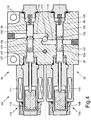
- the ASR control valve 48 is formed as a spool valve having a control piston 63 axially movably guided in a valve bore 62 of a valve housing 61, to which four annular cam grooves 64, 65, 66, 67 are provided.
- the control piston 63 is by means of a magnet armature 70 of an electromagnet 68, whose magnetic coil 69 is connected via a cable 71 to the contacts of a socket 72, against the restoring force of an axially oppositely disposed valve spring 73 axially displaceable.
- the one in the cutting plane of Fig. 2 lying port 74 of the main pressure line 47 is branched within the valve housing 61 in two switching channels 76, 77 which open radially into the valve bore 62 in two spaced-apart axial positions and in the actuated state of the ASR control valve 48 via two control grooves 64, 65 of the control piston 63 with each a connection channel 79, 82 of the bypass lines 49, 50 are connected. While the first switching channel 76 is connected to the connection 74 of the main pressure line 47 via a connecting channel 75, the second switching channel 77 connects directly to this connection 74 as a coaxial extension.
- connection 80 of the second bypass line 50 which is parallel to the cutting plane of Fig. 3 arranged and therefore in Fig. 3 is shown only by dashed lines, via a coaxial connection channel 81 with the in the sectional plane according to Fig. 2 lying connection channel 82 is in communication.
- the one in the cutting plane of Fig. 3 lying terminal 83 of the manifold 51 is branched within the valve housing 61 in two switching channels 85, 86 which open into two further spaced axial positions radially into the valve bore 62 and in the unactuated state of the ASR control valve 48 via two further control grooves 66, 67 of the control piston 63, each having a connection channel 88, 90 of the brake valves 13, 14 outgoing return lines 11, 12 are connected.
- the first switching channel 85 is connected to the connection 83 of the collecting line 51 via a connecting channel 84
- the second switching channel 86 connects directly to this connection 83 as a coaxial extension.
- the in the sectional plane of Fig. 2 lying terminals 87, 89 of the two return lines 11, 12 each go directly into a coaxial connection channel 88, 90 via.
- the ASR control valve 48 has two ventilation channels 91, 92, which in the sectional plane of Fig. 3 lead inside the valve housing 61 from both front ends of the valve bore 62 to one of the switching channels 85, 86 of the manifold 51. Due to leakage in the front ends of the valve bore 62 reaching pressure medium is thus relatively low resistance in an axial displacement of the control piston 63 pressed into the ventilation channels 91, 92 and flows from there via the port 83 of the manifold 51 back into the reservoir. 4
- annular relief grooves 93, 94, 95, 96 which are arranged at axial positions at which in the unactuated or actuated state of the ASR control valve 48 each have a connection or switching channel 76, 77, 85, 90 outside the control grooves 64, 65, 66, 67 of the control piston 63 opens into the valve bore 62.
- the pressure applied to the mouth of the respective connection or switching channel 76, 77, 85, 90 in the valve bore 62 is circumferentially distributed by the respective relief groove 93, 94, 95, 96, so that an effective on the control piston 63 radial transverse force and a consequent increased friction between the control piston 63 and the inner wall of the valve bore 62 can be avoided.
- the inlet valve 22 and the outlet valve 30 are designed as substantially identical 2/2-way magnetic control valves, each with a single cam 101, 103, each as a slide valve with a in a valve bore 98, 99 of a common valve housing 97 axially movable control piston 100, executed and arranged axially parallel in the valve housing 97.
- the control pistons 100, 101 of the inlet valve 22 and the outlet valve 30 are connected in each case via a coupling rod with the armature 106, 112 of a respective associated electromagnet 104, 110.
- At the armature-distant axial end of the control piston 100, 102 acts on this in each case the restoring force of an associated valve spring 109, 115.
- the magnetic coil 105, 111 of the two electromagnets 104, 110 is connected via a respective cable 107, 113 with the contacts of a socket 108, 114.
- connection 116 of the output-side section 18b of the wheel brake line 18 is branched within the valve housing 97 into two switching channels 118, 119 which open radially into the valve bore 98, 99 of the inlet valve 22 or the outlet valve 30 in two spaced-apart axial positions.
- the in the sectional plane of Fig. 4 lying switching channels 118, 119 are connected via a connection channel 117 with the port 116 of the output-side portion 18b of the wheel brake line 18 in conjunction, which together with the coaxially arranged to this connection channel 117 in the sectional plane of Fig. 7 lies.
- the one switching channel 118 is connected in the unactuated state of the inlet valve 22 via the associated control groove 102 with a connection channel 121 of the main brake line 16 branching input side portion 18a of Radbrems Koch 18, in coaxial extension of the relevant terminal 120 in the sectional plane of Fig. 5 lies.
- the other switching channel 119 is connected in the actuated state of the outlet valve 30 via the associated control groove 103 with a connection channel 123 of the leading into the reservoir 4 return line 34, in coaxial extension of the relevant terminal 122 in the sectional plane of Fig. 6 lies.
- the check valve 26 has a of a valve spring 124 against a valve seat 126 depressed ball 125 and is in a in the sectional plane of Fig. 7 lying valve bore 127 of the valve housing 97 is arranged.
- This valve bore 127 opens at the end into an axially parallel to the valve holes 98, 99 of the inlet valve 22 and the outlet valve 30 disposed within the valve housing 97, via the connection channel 117 to the terminal 116 of the output-side portion 18b of the wheel brake line 18 communicating communication channel 128.
- the valve spring 124 outside of the valve seat 126 is the valve bore 127 of the check valve 26 via a further connecting channel 129 and the relevant connection channel 121 to the terminal 120 of the input-side portion 18a of the wheel brake line 18 in connection.
- the inlet valve 22 and the outlet valve 30 each have two ventilation channels 130, 131; 132, 133, which lead within the valve housing 97 from both front ends of the respective valve bore 98, 99 to the connection channel 123 of the return line 34.
- the inlet valve 22 and the outlet valve 30 each have two ventilation channels 130, 131; 132, 133, which lead within the valve housing 97 from both front ends of the respective valve bore 98, 99 to the connection channel 123 of the return line 34.
- control pistons 100, 102 of the inlet valve 22 and the outlet valve 30 are each provided with an annular relief groove 134, 136 for their radial pressure relief, which are each arranged at an axial position, at which in the actuated state of the inlet valve 22, the connection channel 121 of the input-side section 18a of the wheel brake line 18 and in the unactuated state of the exhaust valve 30 of the switching channel 119 of the output-side portion 18b of the wheel brake line 18 outside the control groove 101, 103 of the respective control piston 100, 102 opens into the associated valve bore 98, 99.
- the second to the control piston 100, 102 of the inlet valve 22 and the exhaust valve 30 existing. Ring grooves 135, 137 are due to the largely identical design of the valves 22, 30 and in the present case have no special function.
Landscapes
- Physics & Mathematics (AREA)
- Engineering & Computer Science (AREA)
- Fluid Mechanics (AREA)
- Electromagnetism (AREA)
- Transportation (AREA)
- Mechanical Engineering (AREA)
- Regulating Braking Force (AREA)
- Braking Systems And Boosters (AREA)
- Valves And Accessory Devices For Braking Systems (AREA)
- Valve Housings (AREA)
- Multiple-Way Valves (AREA)
Claims (10)
- Système de freinage hydraulique (1), assisté par une force extérieure, d'un véhicule à roues, le système de freinage comprenant deux circuits de freinage (2, 3), qui sont pourvus chacun d'une conduite de frein principale (16, 17) pouvant être raccordée à une conduite montante sous pression (7, 8) ou à une conduite de retour sans pression (11, 12) par le biais d'une vanne de frein (13, 14) et d'une pluralité de conduites de frein de roue (18a, 18b ; 19a, 19b, 20a, 20b ; 21a, 21b) dérivant de la conduite de frein principale et menant chacune à un cylindre de frein de roue (38, 39, 40, 41) d'un frein de roue, un ensemble de vannes d'une commande ABS, qui comporte au niveau de chaque frein de roue une vanne d'entrée (22, 23, 24, 25) disposée dans la conduite de frein de roue respective (18a, 18b ; 19a, 19b, 20a, 20b ; 21a, 21b) et pourvue d'une vanne anti-retour (26, 27, 28, 29) montée en parallèle et une vanne de sortie (30, 31, 32, 33) allant du cylindre de frein de roue respectif (38, 39, 40, 41) jusque dans une conduite de retour (34, 35, 36, 37), et un ensemble de vannes d'une commande ASR au moyen duquel une conduite sous pression peut être raccordée directement aux conduites de frein principales (16, 17) et les conduites de retour (11, 12) peuvent être bloquées, caractérisé en ce que l'ensemble de vannes de la commande ASR comporte une vanne de commande ASR unique (48) qui est conçue comme une vanne de commutation magnétique à 6/2 voies et au moyen de laquelle, à l'état non actionné, une conduite de pression principale sous pression (47) est coupée des deux conduites de dérivation (49, 50) menant directement à l'une des conduites de frein principales (16, 17) et les deux conduites de retour (11, 12) sont reliées à une conduite collectrice sans pression (51) et au moyen de laquelle, à l'état actionné, la conduite de pression principale (47) est raccordée aux deux conduites de dérivation (49, 50) et les deux conduites de retour (11, 12) sont coupées de la conduite collectrice (51).
- Système de freinage selon la revendication 1, caractérisé en ce que la vanne de commande ASR (48) est conçue comme une vanne à tiroir comportant un piston de commande (63) guidé de manière mobile axialement dans un alésage de vanne (62) d'un boîtier de vanne (61) et pourvu de quatre gorges de commande (64, 65, 66, 67), en ce que le raccord (74) de la conduite de pression principale (47) à l'intérieur du boîtier de vanne (61) est dérivé en deux canaux de commutation (76, 77) qui débouchent, dans deux positions axiales espacées l'une de l'autre, radialement dans l'alésage de vanne (62) et qui sont raccordés, lorsque la vanne de commande ASR (48) est actionnée, chacun à un canal de raccordement (79, 82) des conduites de dérivation (49, 50) par le biais de deux gorges de commande (64, 65) du piston de commande (63), et en ce que le raccord (83) de la conduite collectrice (51) à l'intérieur du boîtier de vanne (61) est dérivé en deux canaux de commutation (85, 86) qui débouchent radialement dans l'alésage de vanne (62) dans deux autres positions axiales espacées l'une de l'autre et qui sont raccordes, lorsque la vanne de commande ASR (48) n'est pas actionnée, chacun à un canal de raccordement (88, 90) des conduites de retour (11, 12), partant des vannes de frein (13, 14), par le biais de deux autres gorges de commande (66, 67) du piston de commande (63).
- Système de freinage selon la revendication 1 ou 2, caractérisé en ce que la vanne de commande ASR (48) comporte, pour la décharge de pression axiale du piston de commande (63), deux canaux de ventilation (91, 92) qui vont, à l'intérieur du boîtier de vanne (61), des deux extrémités frontales de l'alésage de vanne (62) respectivement à l'un des canaux de commutation (85, 86) de la conduite collectrice (51).
- Système de freinage selon l'une des revendications 1 à 3, caractérisé en ce que le piston de commande (63) est pourvu, pour sa décompression radiale, de gorges de décompression (93, 94, 95, 96) qui sont disposées à des positions axiales à chacune desquelles, lorsque la vanne de commande ASR (48) est actionnée ou n'est pas actionnée, un canal de raccordement ou de commutation (76, 77, 85, 90) débouche dans l'alésage de vanne (62) à l'extérieur des gorges de commande (64, 65, 66, 67) du piston de commande.
- Système de freinage selon l'une des revendications 1 à 4, caractérisé en ce que les vannes d'entrée (22, 23, 24, 25) et les vannes de sortie (30, 31, 32, 33) de la commande ABS sont réalisées sous la forme de vannes de commutation magnétique à 2/2 voies et sont disposées chacune pour chaque cylindre de frein de roue (38, 39, 40, 41) parallèlement à l'axe et conjointement avec la vanne anti-retour respective (26, 27, 28, 29) dans un bloc de vannes (52, 53, 54, 55) comportant un boîtier de vanne commun (97).
- Système de freinage selon la revendication 5, caractérisé en ce que les vannes d'entrée (22, 23, 24, 25) et les vannes de sortie (30, 31, 32, 33) sont conçues chacune comme une vanne à tiroir comportant un piston de commande (100, 102) guidé de manière mobile axialement dans un alésage de vanne (98, 99) du boîtier de vanne (97) et pourvue d'une seule gorge de commande (101, 103) et en ce que le raccord (116) de la partie côté sortie (18b) de la conduite de frein de roue (18) est dérivé, à l'intérieur du boîtier de vanne (97), en deux canaux de commutation (118, 119) qui débouchent radialement, dans deux positions axiales espacées l'une de l'autre, dans l'alésage de vanne (98, 99) de la vanne d'entrée (22) ou de la vanne de sortie (30) et dont un canal de commutation (118) est raccordé, lorsque la vanne d'entrée (22) n'est pas actionnée, à un canal de raccordement (121) de la partie côté entrée (18a) de la conduite de frein de roue (18) par le biais de la gorge de commande associée (101) et dont l'autre canal de commutation (119) est raccordé, lorsque la vanne de sortie (30) est actionnée, à un canal de raccordement (123) d'une conduite de retour (34), menant au réservoir (4), par le biais de la gorge de commande associée (103).
- Système de freinage selon la revendication 5 ou 6, caractérisé en ce que la vanne d'entrée (22) et la vanne de sortie (30) comportent chacune, pour la décompression axiale du piston de commande respectif (100, 102), deux canaux de ventilation (130, 131 ; 132, 133) qui vont, à l'intérieur du boîtier de vanne (97), des deux extrémités frontales de l'alésage de vanne respectif (101, 103) au canal de raccordement (123) de la conduite de retour (34).
- Système de freinage selon l'une des revendications 5 à 7, caractérisé en ce que les pistons de commande (100, 102) de la vanne d'entrée (22) et de la vanne de sortie (30) sont pourvu chacun, pour leur décompression radiale, d'une gorge de décompression (134, 136) qui est disposée dans une position axiale dans laquelle, lorsque la vanne d'entrée (22) est actionnée et que la vanne de sortie (30) n'est pas actionnée, un canal de raccordement ou de commutation (119, 121) débouche dans l'alésage de vanne associé (98, 99) à l'extérieur de la gorge de commande (101, 103) du piston de commande respectif (100, 102).
- Système de freinage selon l'une des revendications 5 à 8, caractérisé en ce que la vanne anti-retour (26) comporte une bille (125) pressée par un ressort de vanne (124) contre un siège de vanne (126) et en ce que la vanne anti-retour (26) est disposée dans un alésage de vanne (127) du boîtier de vanne (97), lequel alésage de vanne est raccordé côté extrémité au raccord (116) de la partie côté sortie (18b) de la conduite de frein de roue (18) à l'intérieur du boîtier de vanne (97) et au raccord (120) de la partie côté entrée (18a) de la conduite de frein de roue (18) à l'extérieur du siège de vanne (126) .
- Système de freinage selon l'une des revendications 1 à 9, caractérisé en ce qu'un capteur de pression (56, 57, 58, 59), qui est raccordé à une unité de commande (60) de la commande ABS et ASR par le biais d'une ligne de signal, est raccordé à chaque partie côté sortie (18b, 19b, 20b, 21b) d'une conduite de frein de roue (18a, 18b, 19a, 19b, 20a, 20b, 21a, 21b).
Applications Claiming Priority (2)
| Application Number | Priority Date | Filing Date | Title |
|---|---|---|---|
| DE102015003201.1A DE102015003201A1 (de) | 2015-03-10 | 2015-03-10 | Hydraulische Bremsanlage |
| PCT/EP2016/000230 WO2016142028A1 (fr) | 2015-03-10 | 2016-02-11 | Système de freinage hydraulique |
Publications (2)
| Publication Number | Publication Date |
|---|---|
| EP3268253A1 EP3268253A1 (fr) | 2018-01-17 |
| EP3268253B1 true EP3268253B1 (fr) | 2019-04-10 |
Family
ID=55361456
Family Applications (1)
| Application Number | Title | Priority Date | Filing Date |
|---|---|---|---|
| EP16704797.6A Active EP3268253B1 (fr) | 2015-03-10 | 2016-02-11 | Système de freinage hydraulique |
Country Status (5)
| Country | Link |
|---|---|
| US (1) | US10086812B2 (fr) |
| EP (1) | EP3268253B1 (fr) |
| JP (1) | JP2018509331A (fr) |
| DE (1) | DE102015003201A1 (fr) |
| WO (1) | WO2016142028A1 (fr) |
Families Citing this family (2)
| Publication number | Priority date | Publication date | Assignee | Title |
|---|---|---|---|---|
| GB2563238B (en) * | 2017-06-07 | 2021-04-28 | Caterpillar Sarl | Fluid delivery system |
| EP3747716B1 (fr) * | 2019-06-03 | 2023-09-13 | Haldex Brake Products Aktiebolag | Ensemble de frein pneumatique d'essieu de véhicule |
Family Cites Families (15)
| Publication number | Priority date | Publication date | Assignee | Title |
|---|---|---|---|---|
| DE3714740A1 (de) * | 1987-05-02 | 1988-11-17 | Teves Gmbh Alfred | Kraftfahrzeug-bremsanlage mit schlupfregelung |
| DE3900852C1 (de) * | 1989-01-13 | 1990-03-01 | Daimler-Benz Aktiengesellschaft, 7000 Stuttgart | Antriebs-Schlupf-Regeleinrichtung (ASR) an einem auch mit einem Antiblockiersystem ausgerüsteten Straßenfahrzeug |
| JP2681695B2 (ja) * | 1989-08-04 | 1997-11-26 | 株式会社ナブコ | ブレーキ装置 |
| DE4106336A1 (de) * | 1991-02-28 | 1992-09-03 | Bosch Gmbh Robert | Hydraulische bremsanlage, insbesondere fuer kraftfahrzeuge |
| US5855417A (en) * | 1994-09-12 | 1999-01-05 | General Motors Corporation | Integral control and isolation valve proportional brake system |
| DE19546056A1 (de) | 1995-12-09 | 1997-06-12 | Teves Gmbh Alfred | Hydraulische Bremsanlage mit Hochdruckquelle und pedalbetätigtem Dosierventil |
| US6053582A (en) * | 1996-08-14 | 2000-04-25 | Kelsey-Hayes Company | Integrated ABS/TC/VSC braking system with separate boost valve |
| US5984432A (en) * | 1997-03-14 | 1999-11-16 | Toyota Jidosha Kabushiki Kaisha | Pressure control apparatus including seating valve controlled by electric current incremented upon valve opening depending upon pressure difference across the valve |
| JPH10250551A (ja) * | 1997-03-17 | 1998-09-22 | Tokico Ltd | ブレーキ液圧制御装置 |
| US6196642B1 (en) * | 1997-05-02 | 2001-03-06 | Akebono Brake Industry Co., Ltd. | Four-piston brake fluid pressure controller with diaphragm |
| DE19859737A1 (de) * | 1998-12-23 | 2000-06-29 | Wabco Gmbh & Co Ohg | Hydraulische Bremsanlage |
| FR2843926B1 (fr) | 2002-09-02 | 2005-05-20 | Poclain Hydraulics Ind | Dispositif anti-patinage et anti-blocage des roues d'un vehicule utilisant le circuit de freinage |
| US7325883B2 (en) * | 2004-10-04 | 2008-02-05 | Continental Teves, Inc. | Hydraulic braking system featuring selectively-coupled pump suction circuits |
| WO2009043343A1 (fr) * | 2007-10-05 | 2009-04-09 | Robert Bosch Gmbh | Système de frein à force extérieure hydraulique |
| DE102009021012A1 (de) | 2008-05-14 | 2009-11-19 | Robert Bosch Gmbh | Hydraulische Bremsanlage und Vorsteueraggregat für eine derartige Bremsanlage |
-
2015
- 2015-03-10 DE DE102015003201.1A patent/DE102015003201A1/de not_active Withdrawn
-
2016
- 2016-02-11 JP JP2017545646A patent/JP2018509331A/ja active Pending
- 2016-02-11 US US15/546,667 patent/US10086812B2/en active Active
- 2016-02-11 WO PCT/EP2016/000230 patent/WO2016142028A1/fr not_active Ceased
- 2016-02-11 EP EP16704797.6A patent/EP3268253B1/fr active Active
Non-Patent Citations (1)
| Title |
|---|
| None * |
Also Published As
| Publication number | Publication date |
|---|---|
| WO2016142028A1 (fr) | 2016-09-15 |
| JP2018509331A (ja) | 2018-04-05 |
| EP3268253A1 (fr) | 2018-01-17 |
| DE102015003201A1 (de) | 2016-09-15 |
| US20180022334A1 (en) | 2018-01-25 |
| US10086812B2 (en) | 2018-10-02 |
Similar Documents
| Publication | Publication Date | Title |
|---|---|---|
| EP0930208B1 (fr) | Système hydraulique de freinage pou véhicules à moteur | |
| EP0504334B1 (fr) | Systeme de freinage avec installation servant a la fois pour la regulation du glissement au freinage et pour la regulation du glissement a l'entrainement | |
| DE3900850C1 (fr) | ||
| DE3900852C1 (de) | Antriebs-Schlupf-Regeleinrichtung (ASR) an einem auch mit einem Antiblockiersystem ausgerüsteten Straßenfahrzeug | |
| EP3665050B1 (fr) | Système de freinage pour véhicules automobiles | |
| DE4102864A1 (de) | Hydraulische zweikreisbremsanlage | |
| WO1994027848A1 (fr) | Systeme de freinage pour automobiles, muni d'un dispositif de regulation pour systeme antiblocage et antipatinage | |
| DE3725594C1 (fr) | ||
| DE4010410A1 (de) | Hydraulische zweikreisbremsanlage | |
| EP0722397B1 (fr) | Systeme de freinage pour vehicules automobiles | |
| DE19639560A1 (de) | Hydraulische Fahrzeugbremsanlage | |
| DE102009028770A1 (de) | Verfahren zur Betätigung einer hydraulischen Fahrzeugbremsanlage | |
| DE112013006076T5 (de) | Bremsanlage mit schaltbarem Pumpenpfad | |
| EP3268253B1 (fr) | Système de freinage hydraulique | |
| DE19933483C1 (de) | Druckmittelbetätigte Fahrzeugbremsanlage | |
| DE2942979C2 (fr) | ||
| DE4011329A1 (de) | Hydraulische zweikreisbremsanlage | |
| DE10319194B3 (de) | Kombinierte hydraulische und elektromechanische Fahrzeugbremsanlage mit einer Bremskraftregeleinrichtung | |
| EP1538044A2 (fr) | Dispositif hydraulique de frein de remorque | |
| EP3371016A1 (fr) | Système de freinage hydraulique | |
| DE4021454A1 (de) | Hydraulische bremsanlage | |
| DE102015015472A1 (de) | Hydraulische Bremsanlage | |
| DE102009055251A1 (de) | Hydraulische Fahrzeugbremsanlage | |
| DE102010042534A1 (de) | Schlupfgeregelte, hydraulische Fahrzeugbremsanlage | |
| DE4014295A1 (de) | Hydraulische zweikreisbremsanlage |
Legal Events
| Date | Code | Title | Description |
|---|---|---|---|
| STAA | Information on the status of an ep patent application or granted ep patent |
Free format text: STATUS: THE INTERNATIONAL PUBLICATION HAS BEEN MADE |
|
| PUAI | Public reference made under article 153(3) epc to a published international application that has entered the european phase |
Free format text: ORIGINAL CODE: 0009012 |
|
| STAA | Information on the status of an ep patent application or granted ep patent |
Free format text: STATUS: REQUEST FOR EXAMINATION WAS MADE |
|
| 17P | Request for examination filed |
Effective date: 20171010 |
|
| AK | Designated contracting states |
Kind code of ref document: A1 Designated state(s): AL AT BE BG CH CY CZ DE DK EE ES FI FR GB GR HR HU IE IS IT LI LT LU LV MC MK MT NL NO PL PT RO RS SE SI SK SM TR |
|
| AX | Request for extension of the european patent |
Extension state: BA ME |
|
| RIN1 | Information on inventor provided before grant (corrected) |
Inventor name: HEINRICH, VOLKER Inventor name: BRUETT, MIRKO Inventor name: ZIELKE, FRANK |
|
| DAV | Request for validation of the european patent (deleted) | ||
| DAX | Request for extension of the european patent (deleted) | ||
| GRAP | Despatch of communication of intention to grant a patent |
Free format text: ORIGINAL CODE: EPIDOSNIGR1 |
|
| STAA | Information on the status of an ep patent application or granted ep patent |
Free format text: STATUS: GRANT OF PATENT IS INTENDED |
|
| INTG | Intention to grant announced |
Effective date: 20181030 |
|
| GRAS | Grant fee paid |
Free format text: ORIGINAL CODE: EPIDOSNIGR3 |
|
| GRAA | (expected) grant |
Free format text: ORIGINAL CODE: 0009210 |
|
| STAA | Information on the status of an ep patent application or granted ep patent |
Free format text: STATUS: THE PATENT HAS BEEN GRANTED |
|
| AK | Designated contracting states |
Kind code of ref document: B1 Designated state(s): AL AT BE BG CH CY CZ DE DK EE ES FI FR GB GR HR HU IE IS IT LI LT LU LV MC MK MT NL NO PL PT RO RS SE SI SK SM TR |
|
| REG | Reference to a national code |
Ref country code: GB Ref legal event code: FG4D Free format text: NOT ENGLISH |
|
| REG | Reference to a national code |
Ref country code: CH Ref legal event code: EP Ref country code: AT Ref legal event code: REF Ref document number: 1118253 Country of ref document: AT Kind code of ref document: T Effective date: 20190415 |
|
| REG | Reference to a national code |
Ref country code: IE Ref legal event code: FG4D Free format text: LANGUAGE OF EP DOCUMENT: GERMAN |
|
| REG | Reference to a national code |
Ref country code: DE Ref legal event code: R096 Ref document number: 502016004115 Country of ref document: DE |
|
| REG | Reference to a national code |
Ref country code: NL Ref legal event code: MP Effective date: 20190410 |
|
| REG | Reference to a national code |
Ref country code: LT Ref legal event code: MG4D |
|
| PG25 | Lapsed in a contracting state [announced via postgrant information from national office to epo] |
Ref country code: NL Free format text: LAPSE BECAUSE OF FAILURE TO SUBMIT A TRANSLATION OF THE DESCRIPTION OR TO PAY THE FEE WITHIN THE PRESCRIBED TIME-LIMIT Effective date: 20190410 |
|
| PG25 | Lapsed in a contracting state [announced via postgrant information from national office to epo] |
Ref country code: FI Free format text: LAPSE BECAUSE OF FAILURE TO SUBMIT A TRANSLATION OF THE DESCRIPTION OR TO PAY THE FEE WITHIN THE PRESCRIBED TIME-LIMIT Effective date: 20190410 Ref country code: PT Free format text: LAPSE BECAUSE OF FAILURE TO SUBMIT A TRANSLATION OF THE DESCRIPTION OR TO PAY THE FEE WITHIN THE PRESCRIBED TIME-LIMIT Effective date: 20190910 Ref country code: AL Free format text: LAPSE BECAUSE OF FAILURE TO SUBMIT A TRANSLATION OF THE DESCRIPTION OR TO PAY THE FEE WITHIN THE PRESCRIBED TIME-LIMIT Effective date: 20190410 Ref country code: NO Free format text: LAPSE BECAUSE OF FAILURE TO SUBMIT A TRANSLATION OF THE DESCRIPTION OR TO PAY THE FEE WITHIN THE PRESCRIBED TIME-LIMIT Effective date: 20190710 Ref country code: HR Free format text: LAPSE BECAUSE OF FAILURE TO SUBMIT A TRANSLATION OF THE DESCRIPTION OR TO PAY THE FEE WITHIN THE PRESCRIBED TIME-LIMIT Effective date: 20190410 Ref country code: SE Free format text: LAPSE BECAUSE OF FAILURE TO SUBMIT A TRANSLATION OF THE DESCRIPTION OR TO PAY THE FEE WITHIN THE PRESCRIBED TIME-LIMIT Effective date: 20190410 Ref country code: LT Free format text: LAPSE BECAUSE OF FAILURE TO SUBMIT A TRANSLATION OF THE DESCRIPTION OR TO PAY THE FEE WITHIN THE PRESCRIBED TIME-LIMIT Effective date: 20190410 Ref country code: ES Free format text: LAPSE BECAUSE OF FAILURE TO SUBMIT A TRANSLATION OF THE DESCRIPTION OR TO PAY THE FEE WITHIN THE PRESCRIBED TIME-LIMIT Effective date: 20190410 |
|
| PG25 | Lapsed in a contracting state [announced via postgrant information from national office to epo] |
Ref country code: LV Free format text: LAPSE BECAUSE OF FAILURE TO SUBMIT A TRANSLATION OF THE DESCRIPTION OR TO PAY THE FEE WITHIN THE PRESCRIBED TIME-LIMIT Effective date: 20190410 Ref country code: BG Free format text: LAPSE BECAUSE OF FAILURE TO SUBMIT A TRANSLATION OF THE DESCRIPTION OR TO PAY THE FEE WITHIN THE PRESCRIBED TIME-LIMIT Effective date: 20190710 Ref country code: RS Free format text: LAPSE BECAUSE OF FAILURE TO SUBMIT A TRANSLATION OF THE DESCRIPTION OR TO PAY THE FEE WITHIN THE PRESCRIBED TIME-LIMIT Effective date: 20190410 Ref country code: PL Free format text: LAPSE BECAUSE OF FAILURE TO SUBMIT A TRANSLATION OF THE DESCRIPTION OR TO PAY THE FEE WITHIN THE PRESCRIBED TIME-LIMIT Effective date: 20190410 Ref country code: GR Free format text: LAPSE BECAUSE OF FAILURE TO SUBMIT A TRANSLATION OF THE DESCRIPTION OR TO PAY THE FEE WITHIN THE PRESCRIBED TIME-LIMIT Effective date: 20190711 |
|
| PG25 | Lapsed in a contracting state [announced via postgrant information from national office to epo] |
Ref country code: IS Free format text: LAPSE BECAUSE OF FAILURE TO SUBMIT A TRANSLATION OF THE DESCRIPTION OR TO PAY THE FEE WITHIN THE PRESCRIBED TIME-LIMIT Effective date: 20190810 |
|
| REG | Reference to a national code |
Ref country code: DE Ref legal event code: R097 Ref document number: 502016004115 Country of ref document: DE |
|
| PG25 | Lapsed in a contracting state [announced via postgrant information from national office to epo] |
Ref country code: RO Free format text: LAPSE BECAUSE OF FAILURE TO SUBMIT A TRANSLATION OF THE DESCRIPTION OR TO PAY THE FEE WITHIN THE PRESCRIBED TIME-LIMIT Effective date: 20190410 Ref country code: SK Free format text: LAPSE BECAUSE OF FAILURE TO SUBMIT A TRANSLATION OF THE DESCRIPTION OR TO PAY THE FEE WITHIN THE PRESCRIBED TIME-LIMIT Effective date: 20190410 Ref country code: DK Free format text: LAPSE BECAUSE OF FAILURE TO SUBMIT A TRANSLATION OF THE DESCRIPTION OR TO PAY THE FEE WITHIN THE PRESCRIBED TIME-LIMIT Effective date: 20190410 Ref country code: EE Free format text: LAPSE BECAUSE OF FAILURE TO SUBMIT A TRANSLATION OF THE DESCRIPTION OR TO PAY THE FEE WITHIN THE PRESCRIBED TIME-LIMIT Effective date: 20190410 Ref country code: CZ Free format text: LAPSE BECAUSE OF FAILURE TO SUBMIT A TRANSLATION OF THE DESCRIPTION OR TO PAY THE FEE WITHIN THE PRESCRIBED TIME-LIMIT Effective date: 20190410 |
|
| PLBE | No opposition filed within time limit |
Free format text: ORIGINAL CODE: 0009261 |
|
| STAA | Information on the status of an ep patent application or granted ep patent |
Free format text: STATUS: NO OPPOSITION FILED WITHIN TIME LIMIT |
|
| PG25 | Lapsed in a contracting state [announced via postgrant information from national office to epo] |
Ref country code: SM Free format text: LAPSE BECAUSE OF FAILURE TO SUBMIT A TRANSLATION OF THE DESCRIPTION OR TO PAY THE FEE WITHIN THE PRESCRIBED TIME-LIMIT Effective date: 20190410 |
|
| 26N | No opposition filed |
Effective date: 20200113 |
|
| PG25 | Lapsed in a contracting state [announced via postgrant information from national office to epo] |
Ref country code: TR Free format text: LAPSE BECAUSE OF FAILURE TO SUBMIT A TRANSLATION OF THE DESCRIPTION OR TO PAY THE FEE WITHIN THE PRESCRIBED TIME-LIMIT Effective date: 20190410 |
|
| PGFP | Annual fee paid to national office [announced via postgrant information from national office to epo] |
Ref country code: IT Payment date: 20200221 Year of fee payment: 5 |
|
| PG25 | Lapsed in a contracting state [announced via postgrant information from national office to epo] |
Ref country code: SI Free format text: LAPSE BECAUSE OF FAILURE TO SUBMIT A TRANSLATION OF THE DESCRIPTION OR TO PAY THE FEE WITHIN THE PRESCRIBED TIME-LIMIT Effective date: 20190410 |
|
| REG | Reference to a national code |
Ref country code: CH Ref legal event code: PL |
|
| REG | Reference to a national code |
Ref country code: BE Ref legal event code: MM Effective date: 20200229 |
|
| PG25 | Lapsed in a contracting state [announced via postgrant information from national office to epo] |
Ref country code: MC Free format text: LAPSE BECAUSE OF FAILURE TO SUBMIT A TRANSLATION OF THE DESCRIPTION OR TO PAY THE FEE WITHIN THE PRESCRIBED TIME-LIMIT Effective date: 20190410 Ref country code: LU Free format text: LAPSE BECAUSE OF NON-PAYMENT OF DUE FEES Effective date: 20200211 |
|
| PG25 | Lapsed in a contracting state [announced via postgrant information from national office to epo] |
Ref country code: CH Free format text: LAPSE BECAUSE OF NON-PAYMENT OF DUE FEES Effective date: 20200229 Ref country code: LI Free format text: LAPSE BECAUSE OF NON-PAYMENT OF DUE FEES Effective date: 20200229 |
|
| PG25 | Lapsed in a contracting state [announced via postgrant information from national office to epo] |
Ref country code: IE Free format text: LAPSE BECAUSE OF NON-PAYMENT OF DUE FEES Effective date: 20200211 |
|
| PG25 | Lapsed in a contracting state [announced via postgrant information from national office to epo] |
Ref country code: BE Free format text: LAPSE BECAUSE OF NON-PAYMENT OF DUE FEES Effective date: 20200229 |
|
| REG | Reference to a national code |
Ref country code: DE Ref legal event code: R081 Ref document number: 502016004115 Country of ref document: DE Owner name: ZF CV SYSTEMS EUROPE BV, BE Free format text: FORMER OWNER: WABCO GMBH, 30453 HANNOVER, DE Ref country code: DE Ref legal event code: R081 Ref document number: 502016004115 Country of ref document: DE Owner name: ZF CV SYSTEMS HANNOVER GMBH, DE Free format text: FORMER OWNER: WABCO GMBH, 30453 HANNOVER, DE |
|
| REG | Reference to a national code |
Ref country code: DE Ref legal event code: R081 Ref document number: 502016004115 Country of ref document: DE Owner name: ZF CV SYSTEMS EUROPE BV, BE Free format text: FORMER OWNER: ZF CV SYSTEMS HANNOVER GMBH, 30453 HANNOVER, DE |
|
| REG | Reference to a national code |
Ref country code: AT Ref legal event code: MM01 Ref document number: 1118253 Country of ref document: AT Kind code of ref document: T Effective date: 20210211 |
|
| REG | Reference to a national code |
Ref country code: DE Ref legal event code: R082 Ref document number: 502016004115 Country of ref document: DE |
|
| PG25 | Lapsed in a contracting state [announced via postgrant information from national office to epo] |
Ref country code: IT Free format text: LAPSE BECAUSE OF NON-PAYMENT OF DUE FEES Effective date: 20210211 Ref country code: AT Free format text: LAPSE BECAUSE OF NON-PAYMENT OF DUE FEES Effective date: 20210211 |
|
| PG25 | Lapsed in a contracting state [announced via postgrant information from national office to epo] |
Ref country code: MT Free format text: LAPSE BECAUSE OF FAILURE TO SUBMIT A TRANSLATION OF THE DESCRIPTION OR TO PAY THE FEE WITHIN THE PRESCRIBED TIME-LIMIT Effective date: 20190410 Ref country code: CY Free format text: LAPSE BECAUSE OF FAILURE TO SUBMIT A TRANSLATION OF THE DESCRIPTION OR TO PAY THE FEE WITHIN THE PRESCRIBED TIME-LIMIT Effective date: 20190410 |
|
| PG25 | Lapsed in a contracting state [announced via postgrant information from national office to epo] |
Ref country code: MK Free format text: LAPSE BECAUSE OF FAILURE TO SUBMIT A TRANSLATION OF THE DESCRIPTION OR TO PAY THE FEE WITHIN THE PRESCRIBED TIME-LIMIT Effective date: 20190410 |
|
| P01 | Opt-out of the competence of the unified patent court (upc) registered |
Effective date: 20230528 |
|
| PGFP | Annual fee paid to national office [announced via postgrant information from national office to epo] |
Ref country code: FR Payment date: 20241209 Year of fee payment: 10 |
|
| PGFP | Annual fee paid to national office [announced via postgrant information from national office to epo] |
Ref country code: GB Payment date: 20251218 Year of fee payment: 11 |
|
| PGFP | Annual fee paid to national office [announced via postgrant information from national office to epo] |
Ref country code: DE Payment date: 20251216 Year of fee payment: 11 |