EP4105613B1 - Système de mesure permettant de mesurer au moins un paramètre d'un fluide - Google Patents
Système de mesure permettant de mesurer au moins un paramètre d'un fluide Download PDFInfo
- Publication number
- EP4105613B1 EP4105613B1 EP22187465.4A EP22187465A EP4105613B1 EP 4105613 B1 EP4105613 B1 EP 4105613B1 EP 22187465 A EP22187465 A EP 22187465A EP 4105613 B1 EP4105613 B1 EP 4105613B1
- Authority
- EP
- European Patent Office
- Prior art keywords
- frequency
- ultrasonic converter
- signal
- ultrasonic
- received signal
- Prior art date
- Legal status (The legal status is an assumption and is not a legal conclusion. Google has not performed a legal analysis and makes no representation as to the accuracy of the status listed.)
- Active
Links
Images



Classifications
-
- G—PHYSICS
- G01—MEASURING; TESTING
- G01F—MEASURING VOLUME, VOLUME FLOW, MASS FLOW OR LIQUID LEVEL; METERING BY VOLUME
- G01F1/00—Measuring the volume flow or mass flow of fluid or fluent solid material wherein the fluid passes through a meter in a continuous flow
- G01F1/66—Measuring the volume flow or mass flow of fluid or fluent solid material wherein the fluid passes through a meter in a continuous flow by measuring frequency, phase shift or propagation time of electromagnetic or other waves, e.g. using ultrasonic flowmeters
- G01F1/662—Constructional details
-
- G—PHYSICS
- G01—MEASURING; TESTING
- G01F—MEASURING VOLUME, VOLUME FLOW, MASS FLOW OR LIQUID LEVEL; METERING BY VOLUME
- G01F1/00—Measuring the volume flow or mass flow of fluid or fluent solid material wherein the fluid passes through a meter in a continuous flow
- G01F1/66—Measuring the volume flow or mass flow of fluid or fluent solid material wherein the fluid passes through a meter in a continuous flow by measuring frequency, phase shift or propagation time of electromagnetic or other waves, e.g. using ultrasonic flowmeters
- G01F1/667—Arrangements of transducers for ultrasonic flowmeters; Circuits for operating ultrasonic flowmeters
-
- G—PHYSICS
- G01—MEASURING; TESTING
- G01F—MEASURING VOLUME, VOLUME FLOW, MASS FLOW OR LIQUID LEVEL; METERING BY VOLUME
- G01F25/00—Testing or calibration of apparatus for measuring volume, volume flow or liquid level or for metering by volume
- G01F25/10—Testing or calibration of apparatus for measuring volume, volume flow or liquid level or for metering by volume of flowmeters
Definitions
- the invention relates to a measuring system, in particular designed as a clamp-on ultrasonic flow meter, for measuring at least one, in particular fluid dynamic, parameter, in particular a flow velocity and/or a volume flow rate, of a fluid, in particular a fluid flowing in a pipeline, in particular a liquid, a gas, or a dispersion.
- a measuring system in particular designed as a clamp-on ultrasonic flow meter, for measuring at least one, in particular fluid dynamic, parameter, in particular a flow velocity and/or a volume flow rate, of a fluid, in particular a fluid flowing in a pipeline, in particular a liquid, a gas, or a dispersion.
- measuring systems are often used to measure parameters of fluids flowing in a pipeline, not least fluid dynamic parameters such as flow velocity and/or volume flow rate.
- These systems are formed by at least two ultrasonic transducers mounted on the outside of a pipe at a distance from one another, as well as an operating and measuring electronics electrically connected to each of the two ultrasonic transducers.
- Measuring systems of the type in question usually comprise a straight, particularly hollow-cylindrical, tube with a lumen surrounded by a tube wall, for example made of steel, which usually corresponds to a right circular cylinder.
- This tube is designed to carry a partial volume of the fluid within its lumen or to be flowed through by the fluid.
- the tube can be designed, for example, as a standalone tube inserted into a pipeline, or as a sub-segment of an existing pipeline, thus as an integral component of the same pipeline.
- Typical tube wall thicknesses for such tubes range from approximately 2 mm to several centimeters.
- Each of the at least two ultrasonic transducers is attached to the tube on an outer side of the tube wall facing away from the lumen of the tube, for example strapped or clamped on, in such a way that each of the ultrasonic transducers is connected via the tube wall to the pipe is acoustically coupled. Furthermore, each of the ultrasonic transducers is configured to convert a time-varying electrical voltage into ultrasonic waves propagating through the pipe wall and further through the fluid guided in the lumen of the pipe, or to receive ultrasonic waves propagating through the fluid guided in the lumen of the pipe and further through the pipe wall and to convert them into a time-varying electrical voltage.
- the at least two ultrasonic transducers are also positioned at a distance from one another on the outside of the pipe wall and aligned in such a way that ultrasonic waves generated by one of the ultrasonic transducers propagate within the fluid in the lumen partially along a sound propagation path serving as a measuring section and are then acoustically coupled into the other ultrasonic transducer via the pipe wall.
- Ultrasonic transducers which are mostly identical in design, are typically each formed by at least one piezoelectric transducer element, for example made of lead zirconate titanate (PZT - Pb[Zr x Ti 1-x ]O 3 ) or another piezoceramic, and by a coupling body, for example made of polyetherimide (PEI), which is coupled to the transducer element in a sound-conductive manner and is designed to provide the best possible sound-conductive, yet long-term stable contact between the ultrasonic transducer and the pipe.
- PZT - Pb[Zr x Ti 1-x ]O 3 lead zirconate titanate
- a coupling body for example made of polyetherimide (PEI), which is coupled to the transducer element in a sound-conductive manner and is designed to provide the best possible sound-conductive, yet long-term stable contact between the ultrasonic transducer and the pipe.
- PEI polyetherimide
- a center frequency is currently typically in the range of approximately 0.5 - 6 MHz with a relative bandwidth, namely a -6 dB bandwidth of approximately 20-30% of the respective center frequency.
- each of the two ultrasonic transducers is typically configured to be operated intermittently as a transmitter converting electrical power into sound power or as a receiver converting sound power into electrical power, or the two ultrasonic transducers are intended to be operated alternately as a transmitter or receiver, such that at most one of the two ultrasonic transducers is always the transmitter.
- the operating and measuring electronics In order to produce a time-varying electrical voltage at the same ultrasonic transducer, which serves as a received signal of the one ultrasonic transducer operated as a receiver, the operating and measuring electronics generate, at least temporarily during operation of the measuring system, a driver signal having a time-varying, for example, bipolar, electrical voltage for the other ultrasonic transducer currently operated as a transmitter, for example in such a way that the respective driver signal for one ultrasonic transducer is complementary to the respective driver signal for the other ultrasonic transducer, at least for a predetermined time interval.
- a driver signal having a time-varying, for example, bipolar, electrical voltage for the other ultrasonic transducer currently operated as a transmitter, for example in such a way that the respective driver signal for one ultrasonic transducer is complementary to the respective driver signal for the other ultrasonic transducer, at least for a predetermined time interval.
- Measuring systems of the type in question not least clamp-on ultrasonic flowmeters designed for measuring fluid dynamic parameters, determine the respective measured values are often based on travel times (t AB , t BA ) required by ultrasonic waves propagating within the lumen of the pipe to traverse the measuring section located in the respective sound propagation path or on the basis of travel time differences (t BA - t AB ), namely on the basis of differences between travel times (t AB ) of ultrasonic waves propagating along the measuring section in a first measuring direction and travel times (t BA ) of ultrasonic waves propagating along the measuring section in a second measuring direction opposite to the first measuring direction.
- the at least two ultrasonic transducers are usually positioned on the outside of the pipe wall and aligned in such a way that the sound propagation path serving as the measuring section has a main propagation direction inclined by a beam angle ( ⁇ F ) relative to an inner diameter of the pipe.
- a length (L) of the measuring section corresponding to a path length of the sound propagation path corresponds to a quotient (D / cos ⁇ F ) of the same inner diameter of the pipe divided by the cosine of the same beam angle.
- the two ultrasonic transducers can, as in the aforementioned WO-A 2013/079264 shown, for example opposite each other or, for example, as in the above-mentioned WO-A 2009/156250 or WO-A 03/098166 shown, be positioned on an imaginary surface line of the pipe at a distance along the same surface line, typically in such a way that the sound propagation path also crosses a central region of the pipe or its lumen or in such a way that a measured transit time difference is proportional to an average flow velocity of the fluid.
- conventional measuring systems use pulsed ultrasonic waves formed into wave packets with a limited number of oscillations.
- the wave packets are generated in pulses with a predeterminable firing rate that is usually kept constant over a longer period of time.
- the drive signal supplied by the operating and measuring electronics for the respective ultrasonic transducer has a voltage in the form of a sequence of rectangular or sinusoidal voltage pulses (bursts) formed into pulse packets at a rate corresponding to the firing rate.
- V 0 L 2 ⁇ sin ⁇ F ⁇ t ba ⁇ t ab t ab ⁇ t ba ;
- the beam angle and the associated path length depend, among other things, on the alignment of the ultrasonic transducers relative to the pipe as well as on the sound velocities and acoustic impedances established in the measuring system that are relevant for sound propagation.
- the beam angle can be calculated in advance in the form of a nominal beam angle ( ⁇ F,nom ), for example by applying a beam acoustic model approach that assumes plane wavefronts using Snell's law of refraction for acoustics, in order to then be used to determine the measured value for at least one parameter.
- the beam angle ( ⁇ F ) actually established in the measuring system during the measurement corresponds as precisely as possible to the nominal beam angle ( ⁇ F,nom ) used to calculate the measured values for the parameter and that any angular deviation ( ⁇ F ) between the nominal beam angle ( ⁇ F,nom ) and the actual beam angle ( ⁇ F ) is as small as possible.
- a particular problem of measuring systems of the type in question is, among other things, that, as for example in the " IEEE TRANSACTIONS ON ULTRASONICS, FERROELECTRICS, AND FREQUENCY CONTROL, VOL. 43, NO. 4, JULY 1996 - Acoustic Transfer Function of the Clamp-On Flowmeter, Bernhard Funck and Andreas Mitzkus", the pipe naturally has a multitude of vibration modes in which the pipe wall executes or can execute Lamb waves, namely vibrations forming mixed pressure and shear waves, such that the pipe wall is deflected both in the radial direction and in a longitudinal direction of the pipe (Lamb wave vibration modes).
- Lamb waves can be both symmetrical waves (S0, S1, S2, ...Sn) and asymmetrical waves (A0, A1, A2, ...An).
- several of the aforementioned Lamb wave vibration modes can each have resonance frequencies that lie within the bandwidth of the respective ultrasonic transducer, thus close to its center frequency, or within the bandwidth of the respectively excited ultrasonic waves, whereby the actual resonance frequencies of the Lamb wave vibration modes or The respective position of their resonance frequencies in the frequency range can usually only be determined approximately in advance, for example, based on the aforementioned characteristics or material properties of the measuring system.
- Clamp-on ultrasonic flowmeters generate the drive signal using the operating and measuring electronics, for example, by appropriately adapting the formation of the aforementioned pulse packets or bursts, so that the respective received signal exhibits maximum signal power or at least reaches a specified minimum signal power.
- the necessary setting parameters for the operating and measuring electronics are usually determined by appropriate calibration of the measuring system on site, for example, by iteratively adjusting the respective drive signal based on discrete Fourier transforms (DFT) or discrete power density spectra (PSD) determined for the respective received signal during commissioning of the measuring system.
- DFT discrete Fourier transforms
- PSD discrete power density spectra
- measuring systems of the type in question which have been put into operation may exhibit reduced functionality or be subject to malfunction during operation - for example as a result of degradation of the pipe, such as a change in the thickness of the pipe wall, and/or as a result of a change in the transfer function of at least one of the two ultrasonic transducers.
- one object of the invention is to improve measuring systems of the type in question, not least measuring systems designed as clamp-on ultrasonic flowmeters, to the extent that angular deviations of less than 0.4° or relative measurement errors of less than 2%, in particular less than 1.5%, can be achieved. This is particularly true when using conventional ultrasonic transducers or while maintaining mechanical designs or construction principles established in conventional measuring systems. Furthermore, it should be possible to perform a functional test of the measuring system.
- the operating and measuring electronics have a, in particular non-volatile, data memory for storing digital data, for example at least one parameter value for at least one setting parameter characterizing the drive signal for the first ultrasonic transducer, and that the operating and measuring electronics are configured to repeatedly store parameter values for at least one setting parameter characterizing the drive signal for the first ultrasonic transducer in the same data memory, for example in each case together with a time value representing a time of setting or saving the respective parameter value.
- the operating and measuring electronics are further configured to to carry out a check of the functionality of the measuring system, for example a check of the functionality of the first ultrasonic transducer and/or the second ultrasonic transducer, and/or a check of the integrity of the pipe, using the parameter values stored in the data memory for the at least one setting parameter characterizing the drive signal for the first ultrasonic transducer, and/or to detect a degradation of the pipe, for example a change in the wall thickness of the pipe wall, and/or a change in the transfer function of at least one of the two ultrasonic transducers.
- a check of the functionality of the measuring system for example a check of the functionality of the first ultrasonic transducer and/or the second ultrasonic transducer, and/or a check of the integrity of the pipe, using the parameter values stored in the data memory for the at least one setting parameter characterizing the drive signal for the first ultrasonic transducer, and/or to detect a degradation of the pipe, for example a change in the wall thickness of the
- the operating and measuring electronics are further configured to generate at least one measured value for the at least one parameter by means of the received signal of the second ultrasonic transducer.
- the invention also consists in using such a measuring system according to the invention for measuring a flow velocity and/or a volume flow rate and/or a density of a fluid flowing in a pipeline, for example a liquid, a gas, or a dispersion.
- the first ultrasonic transducer has a 6 dB bandwidth extending between a lower first cut-off frequency of the same ultrasonic transducer and an upper second cut-off frequency of the same ultrasonic transducer
- the second ultrasonic transducer has a 6 dB bandwidth extending between a lower first cut-off frequency of the same ultrasonic transducer and an upper second cut-off frequency of the same ultrasonic transducer
- the operating and measuring electronics are designed to generate the drive signal for the first ultrasonic transducer, for example to set the frequency of the dominant signal component of the drive signal for the first ultrasonic transducer such that the frequency of the dominant signal component of the drive signal for the first ultrasonic transducer deviates from the frequency of the dominant signal component of the received signal by no more than 10%, in particular by less than 5%, of a center frequency of the 6 dB bandwidth of the first ultrasonic transducer, defined as a geometric mean of its first cut
- the first ultrasonic transducer has a 6dB bandwidth extending between a lower first limit frequency of the same ultrasonic transducer and an upper second limit frequency of the same ultrasonic transducer and the second ultrasonic transducer has a 6dB bandwidth extending between a lower first cut-off frequency of the same ultrasonic transducer and an upper second cut-off frequency of the same ultrasonic transducer, and that the operating and measuring electronics are set up to generate the drive signal for the first ultrasonic transducer in such a way, for example to set the frequency of the dominant signal component of the drive signal for the first ultrasonic transducer in such a way that the frequency of the dominant signal component of the drive signal for the first ultrasonic transducer deviates from the frequency of the dominant signal component of the received signal by no more than 10%, in particular by less than 5%, of a center frequency of the 6dB bandwidth of the second ultrasonic transducer, defined as a geometric mean of its
- the operating and measuring electronics are designed to change the frequency of the dominant signal component of the drive signal for the first ultrasonic transducer, for example in order to reduce a deviation of the same frequency from the frequency of the dominant signal component of the received signal of the second ultrasonic transducer and/or in such a way that an initially excessive deviation of the same frequency from the frequency of the dominant signal component of the received signal of the second ultrasonic transducer is minimized.
- the operating and measuring electronics are designed to determine an amplitude spectrum of the received signal of the second ultrasonic transducer.
- the operating and measuring electronics are configured to determine a power and/or an amplitude of the dominant signal component of the received signal of the second ultrasonic transducer, for example based on an amplitude spectrum of the same received signal.
- the operating and measuring electronics are designed to determine the frequency of the dominant signal component of the received signal of the second ultrasonic transducer, for example based on an amplitude spectrum of the same received signal.
- the operating and measuring electronics are designed to modulate the voltage of the drive signal for the first ultrasonic transducer, for example, to clock it and/or in such a way that the same voltage is generated as a sequence of two or more rectangular voltage pulses having and/or successive pulse packets at a predetermined time interval.
- the operating and measuring electronics are configured to generate the driver signal for the first ultrasonic transducer such that the dominant signal component of said driver signal initially has an initial frequency, namely adjusted to a predetermined start frequency value, for example, determined in advance based on characteristics of the pipe and/or stored in a non-volatile data memory of the operating and measuring electronics, such that a deviation of said initial frequency of the dominant signal component of the driver signal for the first ultrasonic transducer from the frequency of the dominant signal component of the received signal of the second ultrasonic transducer is greater than a currently achievable minimum deviation and/or such that a deviation of the frequency of the dominant signal component of the driver signal for the first ultrasonic transducer from the frequency of the dominant signal component of the received signal of the second ultrasonic transducer is initially more than
- the operating and measuring electronics are further configured to change the frequency of the dominant signal component of the drive signal for the first ultrasonic transducer, starting from the same initial frequency - for example, to successively increase or successively decrease it - until the frequency of the dominant signal component of the drive signal for the first ultrasonic transducer deviates from the frequency of the dominant signal component of the received signal of the second ultrasonic transducer by no more than
- the operating and measuring electronics are designed to modulate the electrical voltage of the drive signal for the first ultrasonic transducer, such that the electrical voltage is formed as a sequence of voltage pulses, for example, formed into pulse packets arranged successively at a predetermined time interval and/or rectangular, and it is provided that the operating and measuring electronics are designed to modulate the frequency of the dominant To change the signal component of the drive signal for the first ultrasonic transducer over time by generating successive voltage pulses with different pulse widths.
- the operating and measuring electronics are configured to modulate the voltage of the drive signal for the first ultrasonic transducer such that the same voltage is formed as a sequence of pulse packets, for example, each comprising two or more rectangular voltage pulses and/or following one another at a predetermined time interval. Further developing this embodiment of the invention, it is further provided that the operating and measuring electronics are configured to temporally change the frequency of the dominant signal component of the drive signal for the first ultrasonic transducer by generating rectangular voltage pulses formed into a first pulse packet with a pulse width that differs from a pulse width with which rectangular voltage pulses generated subsequently to the first pulse packet, for example, formed into a second pulse packet, are generated.
- the second ultrasonic transducer is designed to convert a time-varying electrical voltage into ultrasonic waves propagating through the pipe wall and further through fluid guided in the lumen of the pipe
- the first ultrasonic transducer is designed to receive ultrasonic waves propagating through fluid guided in the lumen of the pipe and further through the pipe wall and to convert them into a time-varying electrical voltage.
- the operating and measuring electronics are designed to generate a driver signal for the second ultrasonic transducer, which driver signal has a time-varying, for example bipolar and/or pulsed, electrical voltage, for example complementary to the driver signal for the first ultrasonic transducer at least for a predetermined time interval, in order to effect a reception signal of the first ultrasonic transducer having a time-varying electrical voltage, at least temporarily, for example complementary to the driver signal for the first ultrasonic transducer.
- driver signal has a time-varying, for example bipolar and/or pulsed, electrical voltage, for example complementary to the driver signal for the first ultrasonic transducer at least for a predetermined time interval, in order to effect a reception signal of the first ultrasonic transducer having a time-varying electrical voltage, at least temporarily, for example complementary to the driver signal for the first ultrasonic transducer.
- the operating and measuring electronics are designed to generate the at least one measured value both by means of the received signal of the second ultrasonic transducer and by means of the received signal of the first ultrasonic transducer, for example based on a transit time difference determined on the basis of the received signal of the second ultrasonic transducer and the received signal of the first ultrasonic transducer between ultrasonic waves propagating in opposite directions through fluid guided in the lumen of the tube along a predetermined measuring distance and/or based on a cross-correlation of the Received signal of the second ultrasonic transducer and the received signal of the first ultrasonic transducer.
- the operating and measuring electronics can also be configured to generate the at least one measured value both by means of the drive signal for the first ultrasonic transducer and the received signal of the second ultrasonic transducer and by means of the drive signal for the second ultrasonic transducer and the received signal of the first ultrasonic transducer, for example based on both a propagation time determined on the basis of the drive signal for the first ultrasonic transducer and the received signal of the second ultrasonic transducer for ultrasonic waves propagating through fluid guided in the lumen of the tube along a predetermined measuring path in the direction from the first ultrasonic transducer to the second ultrasonic transducer and based on a propagation time determined on the basis of the drive signal for the second ultrasonic transducer and the received signal of the first ultrasonic transducer for ultrasonic waves propagating through fluid guided in the lumen of the tube along the same measuring path in the direction from the second ultrasonic transducer to the first ultrasonic transducer.
- the operating and measuring electronics are set up to generate a received signal of the first ultrasonic transducer having a time-varying electrical voltage, at least temporarily, for example complementary to the drive signal for the first ultrasonic transducer, for the second ultrasonic transducer, said drive signal having a time-varying, for example bipolar and/or pulsed, electrical voltage, for example complementary to the drive signal for the first ultrasonic transducer at least for a predetermined time interval, and it is further provided that the operating and measuring electronics are set up to generate the drive signal for the second ultrasonic transducer in such a way that both the said drive signal and the said received signal of the first ultrasonic transducer each contain a plurality of spectral signal components, but each contain a dominant spectral signal component, namely one having a maximum spectral power density.
- the operating and measuring electronics are configured to modulate the voltage of the drive signal for the second ultrasonic transducer, for example, to clock it and/or in such a way that the same voltage is formed as a sequence of two or more rectangular voltage pulses and/or pulse packets arranged one after the other at a predetermined time interval.
- the operating and measuring electronics can be further configured to generate a sequence of pulse packets, for example, each comprising two or more rectangular pulses, serving as a drive signal, x B (t), for the second ultrasonic transducer (B), and/or to change the frequency of the dominant signal component of the drive signal for the second ultrasonic transducer, for example, to compensate for a deviation of the same frequency from the frequency of the dominant signal component of the received signal. of the first ultrasonic transducer, and/or to generate the drive signal for the second ultrasonic transducer complementary to the drive signal for the first ultrasonic transducer.
- a sequence of pulse packets for example, each comprising two or more rectangular pulses, serving as a drive signal, x B (t), for the second ultrasonic transducer (B), and/or to change the frequency of the dominant signal component of the drive signal for the second ultrasonic transducer, for example, to compensate for a deviation of the same frequency from the frequency of the dominant signal component of the received signal.
- the operating and measuring electronics are configured to generate a time-varying, for example bipolar and/or pulsed, electrical voltage, for example complementary to the drive signal for the first ultrasonic transducer, for the second ultrasonic transducer in order to effect a received signal of the first ultrasonic transducer having a time-varying electrical voltage, at least temporarily, for example complementary to the drive signal for the first ultrasonic transducer, and it is further provided that the operating and measuring electronics are configured to generate the drive signal for the second ultrasonic transducer in such a way that both the said drive signal and the said received signal of the first ultrasonic transducer each contain a plurality of spectral signal components, yet each contain a dominant spectral signal component, namely one having a maximum spectral power density, and that a frequency of the dominant signal component of the drive signal for the second ultrasonic transducer is not increased by more than an amount of
- the operating and measuring electronics are further configured to generate the drive signal for the first ultrasonic transducer and the drive signal for the second ultrasonic transducer in such a way that a frequency of the dominant signal component of the drive signal for the second ultrasonic transducer deviates from a frequency of the dominant signal component of the drive signal for the first ultrasonic transducer by an amount of no more than
- the operating and measuring electronics are designed to generate a receiving signal of the first ultrasonic transducer having a time-varying electrical voltage, at least temporarily, for example complementary to the drive signal for the first ultrasonic transducer, a drive signal for the second ultrasonic transducer having a time-varying, for example bipolar and/or pulsed, electrical voltage, for example complementary to the drive signal for the first ultrasonic transducer at least for a predetermined time interval.
- the operating and measuring electronics are configured to generate the drive signal for the second ultrasonic transducer in such a way that both the same drive signal and the same received signal of the first ultrasonic transducer each contain a plurality of spectral signal components, yet each contain a dominant spectral signal component, namely one having a maximum spectral power density, as well as to convert the received signal of the first ultrasonic transducer into a digital received signal representing the same received signal, and to generate the at least one measured value for the at least one parameter by means of the same digital received signal representing the received signal of the first ultrasonic transducer.
- the operating and measuring electronics are configured to generate a discrete Fourier transformation (DFT) of the digital received signal representing the received signal of the first ultrasonic transducer, and to determine the frequency of the dominant signal component of the received signal of the first ultrasonic transducer based on the same Fourier transformation.
- DFT discrete Fourier transformation
- the operating and measuring electronics are configured to convert the received signal of the second ultrasonic transducer into a digital received signal representing the same received signal, and to generate the at least one measured value for the at least one parameter using the same digital received signal representing the received signal of the second ultrasonic transducer. Further developing this embodiment of the invention, it is further provided that the operating and measuring electronics are configured to generate a discrete Fourier transformation (DFT) of the digital received signal representing the received signal of the second ultrasonic transducer, and to determine the frequency and/or an amplitude and/or a power of the dominant signal component of the received signal of the second ultrasonic transducer based on the same discrete Fourier transformation.
- DFT discrete Fourier transformation
- the tube has inherent Lamb wave oscillation modes in which the tube wall executes or can execute oscillations forming Lamb waves
- the operating and measuring electronics are configured to generate the drive signal for the first ultrasonic transducer such that the frequency of the dominant signal component of said drive signal deviates by an amount of less than
- a center frequency of a 6 dB bandwidth of the first ultrasonic transducer deviates from the resonant frequency of said Lamb wave oscillation mode by more than 5% of said resonant frequency
- a center frequency of a 6dB bandwidth of the second ultrasonic transducer deviates from the resonant frequency of the same Lamb wave oscillation mode by more than 5% of the same resonant frequency
- the pipe wall has a wall thickness which is greater than 2 mm, for example greater than 5 mm.
- the pipe wall has a wall thickness which is less than 10 mm.
- the pipe wall consists of a metal, for example a steel.
- the pipe is designed as an integral component of a pipeline.
- the pipe is inserted into the course of a pipeline, for example in such a way that the pipe is connected to a first segment of the pipeline by means of a first flange connection and to a second segment of the pipeline by means of a second flange connection.
- the first ultrasonic transducer is formed by means of a piezoelectric transducer element, for example made of lead zirconate titanate and/or another piezoceramic, and by means of a coupling body, for example made of polyetherimide (PEI), which is coupled to the same transducer element in a sound-conducting manner.
- a piezoelectric transducer element for example made of lead zirconate titanate and/or another piezoceramic
- a coupling body for example made of polyetherimide (PEI), which is coupled to the same transducer element in a sound-conducting manner.
- PEI polyetherimide
- the second ultrasonic transducer is formed by means of a piezoelectric transducer element, made for example from lead zirconate titanate and/or another piezoceramic, and by means of a coupling body, made for example from polyetherimide (PEI), which is coupled to the same transducer element in a sound-conducting manner.
- a piezoelectric transducer element made for example from lead zirconate titanate and/or another piezoceramic
- a coupling body made for example from polyetherimide (PEI), which is coupled to the same transducer element in a sound-conducting manner.
- PEI polyetherimide
- the first ultrasonic transducer is designed to be operated intermittently as a transmitter converting electrical power into sound power or as a receiver converting sound power into electrical power.
- the second ultrasonic transducer is designed to be operated intermittently, in particular complementarily to the first ultrasonic transducer, as a receiver converting sound power into electrical power or as a transmitter converting electrical power into sound power.
- the operating and measuring electronics are designed to generate the at least one measured value both by means of the received signal of the second ultrasonic transducer and by means of the drive signal for the first ultrasonic transducer, for example based on a transit time determined on the basis of the drive signal for the first ultrasonic transducer and the received signal of the second ultrasonic transducer for ultrasonic waves propagating through fluid guided in the lumen of the tube along a predetermined measuring path in the direction from the first ultrasonic transducer to the second ultrasonic transducer.
- a basic idea of the invention is to improve the measuring accuracy of measuring systems of the type in question by selectively realizing a significant excitation of exactly one dominant Lamb wave oscillation mode of the pipe lying within a frequency range determined by a bandwidth of the drive signal used for the ultrasonic transducers in normal measuring operation as well as by a bandwidth of the ultrasonic transducers themselves, in such a way that a high proportion of sound power generated by the ultrasonic transducer operated as a transmitter is transformed into oscillations of the aforementioned dominant Lamb wave oscillation mode, while at the same time a significant excitation of further Lamb wave oscillation modes of the same pipe is avoided.
- the invention is based, among other things, on the surprising discovery that this can be reproduced with a repeatability sufficient for the desired high measurement accuracy by the aforementioned, comparatively simple to implement, and thus very robust, adjustment of the respective driver signal to the resulting received signal, even with typically only very imprecise knowledge of the actual resonance frequency of the dominant Lamb wave oscillation mode.
- This results in a significant improvement in measurement accuracy compared to the measurement accuracies previously achieved with conventional measuring systems of the type in question, for example by applying the method mentioned above aimed at maximizing the signal power of the received signal.
- a measuring system for measuring at least one, in particular fluid-dynamic, parameter, for example a flow velocity V 0 , a volume flow rate Q V or another flow parameter, of a fluid FL flowing in a pipeline, for example a liquid, a gas or a dispersion, is shown schematically.
- the pipeline can be designed, for example, as a system component of a water supply network, and the fluid can therefore be drinking water or wastewater, for example.
- the fluid FL can also be, for example, crude oil or a liquid fuel, or the pipeline can also be, for example, a component of a petrochemical plant.
- the measuring system comprises a tube 10 with a lumen 10' surrounded by a tube wall 10a, which tube 10 is designed to carry a partial volume of the fluid FL in its lumen or to be flowed through by the same fluid FL.
- the tube 10 can, for example, be designed as an independent tube that is inserted into the course of the aforementioned pipeline, for example by the tube 10, as in Fig. 1a indicated, is connected to a first segment of the pipeline by means of a first flange connection 11 and to a second segment of the pipeline by means of a second flange connection 12.
- the pipe 10 can, however, also be designed, for example, as a partial segment of such a pipeline, for example an already existing one, and thus as an integral component of the same pipeline.
- a wall thickness of the pipe wall can, for example, be in the range of a few millimeters up to a few centimeters. According to one embodiment of the invention, it is particularly provided that the pipe wall has a wall thickness which is greater than 2 mm, in particular also greater than 5 mm. According to a further embodiment of the invention, the pipe wall consists of a metal, for example steel.
- the measuring system further comprises a first ultrasonic transducer A mounted on the tube 10 on an outer side of the tube wall 10a facing away from the lumen of the tube and acoustically coupled via the tube wall to fluid guided in the lumen of the tube, a second ultrasonic transducer B mounted on the tube at a distance from the ultrasonic transducer A on the outer side of the tube wall and acoustically coupled via the tube wall to fluid guided in the lumen of the tube, as well as operating and measuring electronics 2, which are electrically connected to both the first ultrasonic transducer and the second ultrasonic transducer.
- the measuring system can be Accordingly, it could be, for example, a clamp-on ultrasonic flowmeter.
- the operating and measuring electronics 2 can be formed, for example, by a digital signal processor and/or a microcontroller. Furthermore, the operating and measuring electronics 2 can be housed, for example, in a pressure- and/or impact-resistant protective housing H, for example in a protective housing made of a metal, such as stainless steel or aluminum, or a plastic.
- the operating and measuring electronics 2 comprises a data memory MEM, for example a non-volatile one, for storing digital data.
- Digital data to be stored in the data memory MEM can be, for example, data generated during operation of the measuring system, such as measurement data and/or parameter values of setting parameters for the operating and measuring electronics 2.
- the parameter values are also stored together with a respective time value that represents a time of setting or saving the respective parameter value.
- Each of the two, for example identical, ultrasonic transducers A, B can, as is quite common in measuring systems of the type in question, be formed by a piezoelectric transducer element and a coupling body coupled to the same transducer element in a sound-conductive manner.
- at least one of the two ultrasonic transducers A, B is formed by a piezoelectric transducer element made of lead zirconate titanate and/or another piezoceramic and a coupling body made of polyetherimide (PEI).
- PEI polyetherimide
- the ultrasonic transducer A is specifically designed to convert a time-varying, for example pulsed, electrical voltage u A,I into ultrasonic waves W AB, I propagating through the tube wall 10a and further through the fluid guided in the lumen 10' of the tube 10, and thus to be operated as a transmitter that converts electrical power into sound power.
- the ultrasonic transducer B which is identical in construction to the ultrasonic transducer A, for example, is designed to receive ultrasonic waves W AB,II propagating through the fluid guided in the lumen of the tube and further through the tube wall and to convert them into a time-varying electrical voltage u B,II , and thus to be operated as a receiver that converts sound power into electrical power.
- the ultrasonic transducer A naturally has a 6 dB bandwidth BW A,6 dB extending between a lower first cutoff frequency f u,A of the ultrasonic transducer A and an upper second cutoff frequency f o,A of the ultrasonic transducer A; similarly, the ultrasonic transducer B has a 6 dB bandwidth BW B,6 dB extending between a lower first cutoff frequency f u,B of the same ultrasonic transducer B and an upper second cutoff frequency f o,B of the same ultrasonic transducer B.
- a center frequency f 0,A of the 6 dB bandwidth BW A,6 dB of the ultrasonic transducer A defined as a geometric mean f u , A ⁇ f o , A of its first cutoff frequency, f u,A , and its second cutoff frequency, as well as a center frequency f o,B of the 6dB bandwidth BW B,6dB of the ultrasonic transducer B, defined as a geometric mean f u , B ⁇ f o , B of its first cutoff frequency, f u,B , and its second cutoff frequency, can each lie, for example, in a range of 0.5 - 6 MHz.
- each of the ultrasonic transducers can, for example, be selected such that it amounts to approximately 20-30% of the respective center frequency f 0,A or f 0,B , as is quite common in measuring systems of the type in question, or corresponds to a frequency range between approximately 0.2 MHz and approximately 2.5 MHz.
- the two ultrasonic transducers A, B are, as in Fig. 1a schematically shown, positioned at a distance from one another on the outside of the pipe wall 10a and aligned such that the ultrasonic waves W AB,I generated by the ultrasonic transducer A propagate within the fluid in the lumen along a sound propagation path serving as the measuring section AB and then acoustically couple at least partially via the pipe wall into the ultrasonic transducer B (W AB,II ).
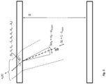
- the two ultrasonic transducers A, B are positioned on the outside of the pipe wall and aligned such that, as in Fig.
- the sound propagation path serving as a measuring section has a main propagation direction inclined by an actual beam angle ⁇ F relative to an inner diameter D of the pipe, such that a length L of the measuring section corresponding to a path length of the sound propagation path corresponds to a quotient D / cos ⁇ F of the same inner diameter D divided by the cosine of the same beam angle ⁇ F.
- the operating and measuring electronics 2 is also configured to generate a driver signal x A (t) for the ultrasonic transducer A, comprising a time-varying electrical voltage u B,II , for the ultrasonic transducer B, or a time-varying electrical voltage u B,II, which serves as a received signal y B (t) , at least temporarily, for the ultrasonic transducer A, or to apply a time-varying, for example, bipolar and/or pulsed, electrical voltage, which serves as a driver signal x A (t) for the ultrasonic transducer A, to the ultrasonic transducer A.
- a driver signal x A (t) for the ultrasonic transducer A comprising a time-varying electrical voltage u B,II , for the ultrasonic transducer B, or a time-varying electrical voltage u B,II, which serves as a received signal y B (t) , at least temporarily, for the ultrasonic transducer A, or to apply
- the driver signal x A (t) provided by the operating and measuring electronics 2 is The measuring system according to the invention is designed so that both the driver signal x A (t) or its electrical voltage u A,I - as well as in Fig. 2a and 3a each based on a normalized voltage u A,I * of the driver signal related to a maximum level or in Fig. 2b and 3b each represented by a normalized amplitude spectrum
- of the voltage u A,I namely related to a maximum value, or from a synopsis Fig. 2a, 2b , 3a and 3b readily apparent - as well as the resulting reception signal y B (t) or its electrical voltage u B,II - as well as in Fig.
- Fig. 4a based on a normalized voltage u A,I * of the received signal related to a maximum level and in Fig. 4b represented by a normalized amplitude spectrum
- a frequency spectrum of the driver signal x A (t), not least also a frequency f xA' of its dominant spectral signal component x A ', can be adapted accordingly to the bandwidths of the ultrasonic transducers A, B and their center frequencies f 0,A and f 0,B , for example in such a way that the dominant spectral signal component x A ' and, with it, the dominant spectral signal component y B ' lie within the 6 dB bandwidths of the ultrasonic transducers A, B or that a 6 dB bandwidth BW xA,6 dB of the driver signal x A (t) or its electrical voltage u A,I is, for example, more than 100 kHz, in particular more than 1 MHz.
- the driver signal x A (t) can advantageously be designed such that the same driver signal x A (t) contains, in addition to a main frequency band corresponding to the aforementioned 6 dB bandwidth BW xA,6 dB , thus containing the dominant spectral signal component x A ', at most such secondary frequency bands whose respective spectral signal components all have a spectral power density that is not less than 6 dB (decibels) lower than the spectral power density S xxA,MAX of the dominant spectral signal component x A ', or whose respective spectral signal components, as also in Fig. 2b and 3b, respectively, all have a (voltage) level reduced by not less than 6 dB compared to a (voltage) level of the dominant spectral signal component x A '.
- the operating and measuring electronics 2 are particularly designed to modulate the voltage u A,I of the drive signal x A (t) for the ultrasonic transducer A, for example, namely to clock it; this is particularly done in such a way that the same voltage u A,I is designed as a sequence of pulse packets generated one after the other with a firing rate 1/Ts, in particular a predetermined one and/or kept constant at least for a predetermined time interval (>> 2 ⁇ T S ), each of which has a predetermined number N, for example, namely two or more, rectangular voltage pulses As in Fig.
- the operating and measuring electronics 2 of the measuring system according to the invention is furthermore also designed to generate at least one measured value X M or a plurality of such measured values for the at least one parameter, for example for the flow velocity V 0 or the volume flow rate Q V , by means of the received signal y B (t) of the ultrasonic transducer B.
- the at least one measured value X M or the measured values can, for example, be visualized on site and/or transmitted - wired via a connected fieldbus and/or wirelessly via radio - to an electronic data processing system, such as a programmable logic controller (PLC) and/or a process control station, for example via a fieldbus, for example in accordance with IEC 61158, IEC 61784-1 or IEC 61784-2, and/or via a radio connection, for example in accordance with IEEE 802.11 or IEEE 802.15.4.
- PLC programmable logic controller
- the operating and measuring electronics 2 are set up to generate the at least one measured value X M both by means of the received signal y B (t) of the ultrasonic transducer B and by means of the drive signal x A (t) for the ultrasonic transducer A, for example based on a transit time t AB determined on the basis of the drive signal x A (t) and the received signal y B (t) for ultrasonic waves W AB,II propagating through fluid guided in the lumen of the tube along the predetermined measuring section AB in the direction from the ultrasonic transducer A to the ultrasonic transducer B.
- the ultrasonic transducer A is furthermore designed to function not only as a transmitter converting electrical power into sound power, but also, as in Fig. 1b presented or from a summary of the Fig. 1a and 1b
- the ultrasonic transducer B can be operated intermittently as a transmitter converting electrical power into sound power or as a receiver converting sound power into electrical power.
- the ultrasonic transducer B can also be configured to be operated intermittently, for example, complementarily to the ultrasonic transducer A, as a receiver converting sound power into electrical power or as a transmitter converting electrical power into sound power.
- the ultrasonic transducer B is also configured to convert a time-varying electrical voltage into ultrasonic waves propagating through the pipe wall and further through the fluid guided in the lumen of the pipe
- the ultrasonic transducer A is configured to receive ultrasonic waves propagating through the fluid guided in the lumen of the pipe and further through the pipe wall and to convert them into a time-varying electrical voltage.
- the operating and measuring electronics 2 is also configured to generate a time-varying, particularly bipolar, electrical voltage driver signal x B (t) for the ultrasonic transducer B, at least temporarily, in particular alternating with the driver signal x A (t) for the same ultrasonic transducer A, in order to produce a time-varying electrical voltage at the ultrasonic transducer A, which can be used as a received signal y A (t) of the ultrasonic transducer A, for example, also having a bandwidth of more than 100 kHz.
- the same driver signal x B (t) can, for example, be designed such that it is complementary to the driver signal x A (t) for the ultrasonic transducer A at least for a predetermined time interval.
- the operating and measuring electronics 2 can also be set up to generate the at least one measured value both by means of the received signal y B (t) of the ultrasonic transducer B and by means of the received signal y A (t) of the ultrasonic transducer A, for example based on a transit time difference determined from the same received signals y B (t), y A (t) between ultrasonic waves propagating in opposite directions through fluid guided in the lumen of the tube along a predetermined measuring distance and/or based on a cross-correlation of the same received signals y B (t), y A (t).
- the operating and measuring electronics 2 can also be configured to generate the at least one measured value both by means of the drive signal x A (t) for the ultrasonic transducer A and the received signal y B (t) of the ultrasonic transducer B and by means of the drive signal x A (t) for the ultrasonic transducer B and the received signal y B (t) of the ultrasonic transducer A, for example based on both a transit time t AB determined on the basis of the drive signal x A (t) and the received signal y B (t) for ultrasonic waves W AB,II propagating through fluid guided in the lumen of the tube along the measuring section AB in the direction from the ultrasonic transducer A to the ultrasonic transducer B and based on a transit time t BA determined on the basis of the drive signal x B (t) and the received signal y A (t) for ultrasonic waves propagating through fluid guided in the lumen of the tube along a measuring section directed opposite to the measuring section
- the beam angle ⁇ F and accordingly also the path length L depend, among other things, on the alignment of the ultrasonic transducers A, B relative to the pipe 10 as well as on the sound velocities and acoustic impedances established in the measuring system that are relevant for sound propagation.
- the beam angle ⁇ F can be calculated in advance as a nominal beam angle ⁇ F,nom ( ⁇ F,nom ⁇ ⁇ F ), for example using Snell's law of refraction for acoustics.
- the determination of the aforementioned nominal values can, for example, be carried out during commissioning of the measuring system by calibrating the fully assembled measuring system using the operating and measuring electronics.
- the operating and measuring electronics 2 is further configured to convert the received signal y B (t) of the ultrasonic transducer B into a digital received signal y Bd representing the same received signal y B (t) and to generate the at least one measured value for the at least one parameter by means of the same digital received signal y Bd representing the received signal y B (t).
- the operating and measuring electronics can also be configured to convert the received signal y A (t) of the ultrasonic transducer A into a digital received signal y Ad representing the same received signal y A (t) and to generate the at least one measured value for the at least one parameter accordingly by means of the same digital reception signal y Ad , for example, namely to generate the at least one measured value for the at least one parameter by means of the digital reception signal y Ad and by means of the digital reception signal y Bd .
- the pipe naturally contains a large number of so-called Lamb wave oscillation modes, namely a large number of asymmetric Lamb wave oscillation modes A 0 , A 1 , A 2 ...A n or a large number of symmetric Lamb wave oscillation modes S 0 , S 1 , S 2 ...S n , in which the pipe wall carries out or can carry out oscillations forming Lamb waves, such that several of these Lamb wave oscillation modes each have resonance frequencies which are within the bandwidth of the two ultrasonic transducers A, B or of the drive signal x A (t) or of the drive signal x B (t), thus within the bandwidth of the respectively excited or received ultrasonic waves W AB,I , W AB,II , W BA,I , W BA,II , whereby the actual resonance frequencies of the Lamb wave oscillation modes or a respective position of the resonance frequencies in the Frequency range are only approximately known or can only be roughly estimated based on the previously known characteristics of the measuring system, for example for
- the operating and measuring electronics 2 of the measuring system is therefore further configured to generate the drive signal x A (t) for the same ultrasonic transducer A in such a way that - as also in Fig.
- a frequency f xA' of the dominant signal component x A ' of the drive signal x A (t) deviates by an amount of not more than
- the operating and measuring electronics 2 initially configures the driver signal x A (t) in such a way that its dominant signal component x A ' has an initial frequency f xA' adjusted to a predetermined start frequency value, in such a way that a deviation of the same (initial) frequency f xA' from the frequency f yB' of the dominant signal component y B ' of the thus generated received signal y B (t) is initially greater than a currently achievable minimum or ultimately achieved deviation Err f , for example also in such a way that the same deviation between the initial frequency f xA' and the associated frequency f yB' is initially more than
- the operating and measuring electronics are designed to change the frequency f xA' of the dominant signal component x A ' of the driver signal x A (t), for example also stepwise (f xA',i ), not least in order to successively reduce the aforementioned deviation of the frequency f xA' from the frequency f yB' and/or to minimize an initially excessive deviation of the frequency f xA' from the frequency f yB' , namely to set it as precisely as possible to a currently achievable minimum deviation Err f or to set the frequency f xA' to a corresponding (optimal) working frequency value, for example namely - as also in Fig.
- the starting frequency value can be, for example, a frequency value derived from at least one characteristic value of at least one of the two ultrasonic transducers A, B - for example, at least one of the previously designated cutoff or center frequencies f u,A , f u,B , f o,A , f o,B , f 0,A , f 0,B - or else an estimated value for a resonance frequency of one of the Lamb wave oscillation modes of the tube, determined in advance based on nominal characteristics of the tube and stored, for example, in the operating and measuring electronics 2, for a resonance frequency of one of the tube's Lamb wave oscillation modes within the aforementioned transmission or operating range of the measuring system.
- the starting frequency value can also be, for example, a frequency f xA' (f prior art ⁇ f xA' ) initially determined for the driver signal x A (t) using a conventional method, for example, aimed at maximizing the signal power of the received signal.
- a frequency f xA' f prior art ⁇ f xA'
- the frequency f xA' corresponds to the dominant signal component x A ' of the driver signal x A (t), as can be seen from a summary of the Fig.
- the frequency of the dominant signal component x A ' of the driver signal x A (t) for the ultrasonic transducer A can also be changed over time, for example, by voltage pulses generated successively by means of the operating and measuring electronics having different pulse widths or by generating rectangular voltage pulses formed into a first pulse packet with a pulse width that deviates from a pulse width with which rectangular voltage pulses generated subsequently in time, for example formed into a second pulse packet, are generated.
- the aforementioned starting value can be stored as a parameter value W f0 for a setting parameter characterizing the driver signal x A (t), namely here the initial frequency to be set for the dominant signal component x A ' during commissioning or after the measuring system is started up for the first time or restarted.
- the same working frequency value can be stored as a parameter value W fx for a (further) setting parameter characterizing the driver signal x A (t) - here namely the optimal frequency corresponding to a minimal deviation of the frequency f xA' from the frequency f yB' , which is to be set as precisely as possible for the dominant signal component x A ' in normal measuring operation - if necessary also together with a corresponding time value (time stamp), for example in the form of a date and/or a time.
- time stamp for example in the form of a date and/or a time.
- the functionality of the measuring system can also be repeatedly checked during operation, for example by occasionally determining the aforementioned optimal frequency f xA' for the dominant signal component x A ' of the driver signal and comparing a currently determined optimal frequency f xA' with an (older) optimal frequency determined at an earlier point in time - here represented by the stored parameter value W fx , and by detecting a reduced functionality or a malfunction of the measuring system - for example as a result of degradation of the pipe, such as a change in the wall thickness of the pipe wall, and/or as a result of a change in the transfer function of at least one of the two ultrasonic transducers A, B - on the basis of any deviation between the two aforementioned optimal frequencies.
- the operating and measuring electronics 2 is also designed to carry out a check of the functionality of the measuring system, for example a check of the functionality of the ultrasonic transducer A and/or the ultrasonic transducer B and/or a check of the integrity of the pipe, using parameter values stored in the data memory MEM for the at least one setting parameter characterizing the drive signal for the ultrasonic transducer A.
- the (instantaneous) frequency f yB' of the dominant signal component y B ' of the received signal y B (t) which is required in addition to the frequency f xA' to determine the deviation of the frequency f xA' from the frequency f yB ' - which in the measuring system according to the invention amounts to less than
- of 0 dB (decibels) corresponds to the spectral signal component of the received signal y B (t) with the greatest amplitude or the greatest spectral power density (S yyB,MAX ) and thus to the sought-after dominant spectral signal component y B ' of the received signal y B (t).
- the operating and measuring electronics is further configured to generate an amplitude spectrum
- the operating and measuring electronics can also be set up to determine or calculate a, possibly also normalized, power density spectrum (PSD) of the received signal y B (t) in order to subsequently determine the dominant spectral signal component y B ' of the received signal y B (t) or its frequency f yB' using the same power density spectrum.
- PSD power density spectrum
- the operating and measuring electronics 2 can furthermore also be set up to determine the amplitude spectrum
- discrete Fourier transformation
- the operating and measuring electronics 2 can furthermore also be configured to determine the frequency f yA' of the dominant signal component y A ' of the received signal y A (t) accordingly based on a discrete Fourier transformation (DFT) of the digital received signal y Ad generated internally by the operating and measuring electronics.
- DFT discrete Fourier transformation
- the measuring accuracy of the measuring system can be improved even further if required, for example by adapting the drive signal x A (t) to the same transfer behavior of the ultrasonic transducers A, B by appropriately designing its frequency spectrum or appropriately selecting its bandwidth.
- the operating and measuring electronics are therefore further configured to generate the driver signal x A (t) in such a way, for example, to set the frequency f xA' of the dominant signal component x A ' of the driver signal x A (t) in such a way or to set the aforementioned operating frequency value in such a way that the frequency f xA' of the dominant signal component x A ' of the driver signal x A (t) deviates by no more than 10%, if possible also by less than 5%, of the center frequency f 0,A of the 6 dB bandwidth, BW A,6dB , of the ultrasonic transducer A from the frequency f yB' of the dominant signal component y B ' of the received signal, and/or that the frequency f xA' of the dominant signal component x A ' of the driver signal x A (t) for the ultrasonic transducer A deviates by no more than 10%, if possible by less than 5%, of
- each of the two ultrasonic transducers A, B is set up to be operated intermittently as a transmitter converting electrical power into sound power or as a receiver converting sound power into electrical power, and that accordingly the operating and measuring electronics 2 is set up to occasionally generate a driver signal x B (t) for ultrasonic transducer B in order to effect the received signal y A (t) of the ultrasonic transducer A, in particular complementary to the driver signal x A (t), the operating and measuring electronics 2 is further set up according to a further embodiment of the invention to generate the same driver signal x B (t) for the ultrasonic transducer B in such a way that both the same driver signal x B (t) and the same received signal y A (t) of the ultrasonic transducer A each have a plurality of spectral signal components x B,i , y A,i , but each have a dominant, namely a maximum spectral power density S xxB,MAX ; S yyA
- the driver signal x B (t) can, for example, be designed in such a way that it has a temporal level curve which is only shifted in time compared to a temporal level curve of the driver signal x A (t), for example by a time value corresponding to half a firing rate (0.5 ⁇ T S ), but otherwise corresponds to the same level curve of the driver signal x A (t) at least for a predetermined time interval (>> 2 ⁇ T S ).
- the operating and measuring electronics 2 is further configured to modulate the voltage u B,I of the driver signal x B (t) for the ultrasonic transducer B, for example, namely to clock it; this is done in particular in the same way as for the driver signal x A (t) or in such a way that the same voltage u B,I is designed as a sequence of two or more rectangular voltage pulses and/or pulse packets arranged one after the other at a predetermined time interval.
- the operating and measuring electronics 2 can also be configured to change the frequency f xB' during operation, for example to reduce a deviation of the same frequency f xB' from the frequency f yA' of the dominant signal component y A ' of the received signal y A (t) of the ultrasonic transducer A or to adapt the frequency f xB' to the frequency f xA' accordingly.
Landscapes
- Physics & Mathematics (AREA)
- Electromagnetism (AREA)
- Fluid Mechanics (AREA)
- General Physics & Mathematics (AREA)
- Measuring Volume Flow (AREA)
- Investigating Or Analyzing Materials By The Use Of Ultrasonic Waves (AREA)
Claims (17)
- Système de mesure destiné à la mesure d'au moins un paramètre, notamment un paramètre de dynamique des fluides, notamment une vitesse d'écoulement et/ou un débit volumique, d'un fluide (FL), notamment d'un liquide, d'un gaz ou d'une dispersion - notamment s'écoulant dans une conduite - lequel système de mesure est notamment conçu en tant que débitmètre à ultrasons clamp-on, lequel système de mesure comprend :- un tube (10) avec un canal intérieur (10') entouré par une paroi de tube (10a), lequel tube est conçu pour guider dans son canal intérieur un volume partiel du fluide ou pour être traversé par le fluide ;- un premier transducteur à ultrasons (A) monté sur le tube sur un côté extérieur de la paroi du tube opposé au canal intérieur du tube, lequel transducteur est couplé acoustiquement via la paroi du tube à un fluide guidé dans le canal intérieur du tube, lequel transducteur est conçu pour convertir une tension électrique variant dans le temps, notamment pulsée, en ondes ultrasonores (WAB,I) se propageant à travers la paroi du tube et plus loin à travers le fluide guidé dans le canal intérieur du tube ;- un deuxième transducteur à ultrasons (B), notamment de construction identique au premier transducteur d'ultrasons, monté à distance du premier transducteur à ultrasons sur le tube sur un côté extérieur de la paroi du tube opposé au canal intérieur du tube, lequel transducteur est couplé acoustiquement via la paroi du tube à un fluide guidé dans le canal intérieur du tube, lequel transducteur est conçu pour recevoir des ondes ultrasonores (WAB,II) se propageant à travers le fluide guidé dans le canal intérieur du tube et plus loin à travers la paroi du tube et pour les convertir en une tension électrique variant dans le temps ;- ainsi qu'une électronique de fonctionnement et de mesure (2) reliée électriquement aussi bien au premier transducteur à ultrasons qu'au deuxième transducteur à ultrasons, laquelle électronique est constituée notamment d'un processeur de signaux numériques et/ou d'un microcontrôleur, l'électronique de fonctionnement et de mesure comprenant une mémoire de données (MEM), notamment non volatile, destinée à mémoriser des données numériques, notamment au moins une valeur de paramètre pour au moins un paramètre de réglage caractérisant un signal d'attaque pour le premier transducteur à ultrasons (A) ;- l'électronique de fonctionnement et de mesure étant conçue - en vue de produire un signal de réception, yB(t), du deuxième transducteur à ultrasons (B), présentant une tension électrique, uB,II, variable dans le temps - pour générer au moins temporairement un signal d'attaque, xA(t), présentant une tension électrique, uA,I, variable dans le temps, notamment bipolaire et/ou pulsée, pour le premier transducteur à ultrasons (A), de telle sorte- qu'aussi bien ledit signal d'attaque, xA(t), que ledit signal de réception, yB(t), contiennent respectivement une pluralité de composantes de signal spectrales (xA,i, yb,i), mais respectivement une composante de signal spectrale dominante (xA', yB'), à savoir présentant respectivement une densité de puissance spectrale maximale (SxxA,MAX ; SyyB,MAX),- et de telle sorte qu'une fréquence, fxA', de la composante de signal dominante (xA') du signal d'attaque, xA(t), pour le premier transducteur à ultrasons (A) s'écarte d'une valeur non supérieure à |±100 kHz|, notamment d'une valeur inférieure à |±50 kHz|, par rapport à une fréquence, fyB', de la composante de signal dominante (yB') du signal de réception, yB(t), du deuxième transducteur à ultrasons (B) et/ou de pas plus de 10 %, notamment de moins de 5 %, de la fréquence, fyB', de la composante de signal dominante (yB') du signal de réception, yB(t), du deuxième transducteur à ultrasons (B) par rapport à la dite fréquence, fyB' ;- et l'électronique de fonctionnement et de mesure étant conçue pour mémoriser des valeurs de paramètres pour au moins un paramètre de réglage caractérisant le signal d'attaque pour le premier transducteur à ultrasons (A) de manière récurrente dans la mémoire de données, notamment à chaque fois avec une valeur de temps représentant un instant d'un réglage ou d'une mémorisation de la valeur de paramètre respective ;- l'électronique de fonctionnement et de mesure étant conçue pour,-- effectuer - en utilisant des valeurs de paramètres mémorisées dans la mémoire de données (MEM) pour l'au moins un paramètre de réglage caractérisant le signal d'attaque pour le premier transducteur à ultrasons (A) - un contrôle d'une aptitude au fonctionnement du système de mesure, notamment à savoir un contrôle d'une aptitude au fonctionnement du premier transducteur à ultrasons (A) et/ou du deuxième transducteur à ultrasons (B), et/ou un contrôle d'une intégrité du tube,-- et/ou détecter - en utilisant au moins une valeur de paramètre mémorisée dans la mémoire de données pour l'au moins un paramètre de réglage caractérisant le signal d'attaque pour le premier transducteur à ultrasons (A) - une dégradation du tube, notamment une modification d'une épaisseur de la paroi du tube, et/ou une modification d'une fonction de transmission d'au moins un des deux transducteurs à ultrasons ;- et l'électronique de fonctionnement et de mesure étant conçue pour générer au moins une valeur de mesure (XM) pour l'au moins un paramètre au moyen du signal de réception, yB(t), du deuxième transducteur à ultrasons (B).
- Système de mesure selon la revendication précédente,- pour lequel le premier transducteur à ultrasons (A) présente une largeur de bande de 6 dB, BWA,6dB, s'étendant entre une première fréquence limite inférieure, fu,A, dudit transducteur à ultrasons (A) et une deuxième fréquence limite supérieure, fo,A, dudit transducteur à ultrasons (A), et le deuxième transducteur à ultrasons présente une largeur de bande de 6 dB, BWB,6dB, s'étendant entre une première fréquence limite inférieure, fu,B, dudit transducteur à ultrasons (B) et une deuxième fréquence limite supérieure, fo,B, dudit transducteur à ultrasons (B),- et pour lequel l'électronique de fonctionnement et de mesure est conçue pour générer le signal d'attaque, xA(t), pour le premier transducteur à ultrasons (A) - notamment pour régler la fréquence, fxA', de la composante de signal dominante (xA') du signal d'attaque, xA(t), pour le premier transducteur à ultrasons (A) - de telle sorte-- que la fréquence, fxA', de la composante de signal dominante (xA') du signal d'attaque, xA(t), pour le premier transducteur à ultrasons (A) ne s'écarte pas de plus de 10 %, notamment ne s'écarte pas de moins de 5 %, d'une fréquence centrale, fo,A, de la largeur de bande de 6 dB, BWA,6dB, du premier transducteur à ultrasons (A), laquelle fréquence est définie comme une moyenne géométrique,
 -- que la fréquence, fxA', de la composante de signal dominante (xA') du signal d'attaque, xA(t), pour le premier transducteur à ultrasons (A) ne s'écarte pas de plus de 10 %, notamment ne s'écarte pas de moins de 5 %, d'une fréquence centrale, fo,B, de la largeur de bande de 6 dB, BWB,6dB, du deuxième transducteur à ultrasons (B), laquelle fréquence est définie comme une moyenne géométrique,
- Système de mesure selon l'une des revendications précédentes,- pour lequel des modes de vibration d'ondes de Lamb (S0, S1, S2 ... Sn, A0, A1, A2 ... An) sont inhérents au tube, modes dans lesquels la paroi du tube exécute ou peut exécuter des vibrations formant des ondes de Lamb,- et pour lequel l'électronique de fonctionnement et de mesure est conçue pour générer le signal d'attaque, xA(t), pour le premier transducteur à ultrasons (A), de telle sorte que la fréquence de la composante de signal dominante (xA') dudit signal d'attaque, xA(t), s'écarte d'une valeur inférieure à |±100 kHz|, notamment d'une valeur inférieure à |±50 kHz|, par rapport à une fréquence de résonance de l'un des modes de vibration d'ondes de Lamb et/ou de moins de 10 %, notamment de moins de 5 %, d'une fréquence de résonance de l'un des modes de vibration d'ondes de Lamb par rapport à ladite fréquence de résonance.
- Système de mesure selon les revendications 2 et 3,- pour lequel la fréquence centrale, f0,A, de la largeur de bande de 6 dB, BWA,6dB, du premier transducteur à ultrasons (A) s'écarte de la fréquence de résonance dudit mode de vibration d'ondes de Lamb de plus de 5 % de ladite fréquence de résonance ; et/ou- pour lequel la fréquence centrale, f0,B, de la largeur de bande de 6 dB, BWB,6dB, du deuxième transducteur à ultrasons (B) s'écarte de la fréquence de résonance dudit mode de vibration d'onde de Lamb de plus de 5 % de ladite fréquence de résonance.
- Système de mesure selon l'une des revendications précédentes,- pour lequel l'électronique de fonctionnement et de mesure est conçue pour déterminer un spectre d'amplitude, |YB|, du signal de réception, yB(t), du deuxième transducteur à ultrasons (B) ; et/ou- pour lequel l'électronique de fonctionnement et de mesure est conçue pour déterminer une puissance et/ou une amplitude de la composante de signal dominante (yB') du signal de réception, yB(t), du deuxième transducteur à ultrasons (B), notamment sur la base d'un spectre d'amplitude, |YB|, dudit signal de réception, yB(t) ; et/ou- pour lequel l'électronique de fonctionnement et de mesure est conçue pour déterminer la fréquence de la composante de signal dominante (yB') du signal de réception, yB(t), du deuxième transducteur à ultrasons (B), notamment sur la base d'un spectre d'amplitude, |YB|, dudit signal de réception, yB(t).
- Système de mesure selon l'une des revendications précédentes, pour lequel l'électronique de fonctionnement et de mesure est conçue pour moduler, notamment pour cadencer, la tension du signal d'attaque, xA(t), pour le premier transducteur à ultrasons (A), et/ou de telle sorte que ladite tension soit conçue comme une suite de paquets d'impulsions présentant respectivement deux ou plusieurs impulsions de tension rectangulaires et/ou se succédant à un intervalle de temps prédéfini.
- Système de mesure selon la revendication précédente,- pour lequel l'électronique de fonctionnement et de mesure est conçue pour moduler la tension du signal d'attaque, xA(t), pour le premier transducteur à ultrasons (A), de telle sorte que ladite tension soit conçue comme une suite de paquets d'impulsions présentant respectivement deux ou plusieurs impulsions de tension rectangulaires et/ou se succédant à un intervalle de temps prédéfini ;- et pour lequel l'électronique de fonctionnement et de mesure est conçue pour modifier dans le temps la fréquence, fxA', de la composante de signal dominante (xA') du signal d'attaque, xA(t), pour le premier transducteur à ultrasons (A), en générant des impulsions de tension rectangulaires formées en un premier paquet d'impulsions avec une largeur d'impulsion qui diffère d'une largeur d'impulsion avec laquelle des impulsions de tension rectangulaires générées à la suite du premier paquet d'impulsions, notamment formées en un deuxième paquet d'impulsions, sont générées dans le temps.
- Système de mesure selon la revendication précédente, pour lequel l'électronique de fonctionnement et de mesure est conçue pour modifier dans le temps la fréquence de la composante de signal dominante (xA') du signal d'attaque, xA(t), pour le premier transducteur à ultrasons (A), en ce que des impulsions de tension générées successivement dans le temps présentent des largeurs d'impulsion différentes.
- Système de mesure selon l'une des revendications précédentes, pour lequel l'électronique de fonctionnement et de mesure est conçue pour générer le signal d'attaque, xA(t), pour le premier transducteur à ultrasons (A), de telle sorte que la composante de signal dominante (xA') dudit signal d'attaque, xA(t), présente dans un premier temps une valeur initiale, à savoir une fréquence ajustée à une valeur de fréquence de départ prédéfinie, notamment sur la base de données caractéristiques du tube et/ou d'au moins une valeur caractéristique d'au moins l'un des transducteurs à ultrasons et/ou conservée dans une mémoire de données non volatile de l'électronique de fonctionnement et de mesure, de telle sorte qu'un écart de ladite fréquence initiale de la composante de signal dominante (xA') du signal d'attaque, xA(t), pour le premier transducteur à ultrasons (A), par rapport à la fréquence, fyB', de la composante de signal dominante (yB') du signal de réception, yB(t), du deuxième transducteur à ultrasons (B) est supérieur à un écart minimal pouvant être atteint momentanément à cet effet et/ou de telle sorte qu'un écart de la fréquence, fxA, de la composante de signal dominante (xA') du signal d'attaque, xA(t), pour le premier transducteur à ultrasons (A) par rapport à la fréquence, fyB', de la composante de signal dominante (xB') du signal de réception, yB(t), du deuxième transducteur à ultrasons (B) est dans un premier temps supérieur à |±100 kHz| et/ou supérieur à 10 % de la fréquence, fyB', de la composante de signal dominante (yB') du signal de réception, yB(t), du deuxième transducteur à ultrasons (B).
- Système de mesure selon la revendication précédente, pour lequel l'électronique de fonctionnement et de mesure est conçue pour modifier, à partir de ladite fréquence initiale, la fréquence, fxA', de la composante de signal dominante (xA') du signal d'attaque, xA(t), pour le premier transducteur à ultrasons (A), notamment pour augmenter successivement ou diminuer successivement, au moins jusqu'à ce que la fréquence, fxA', de la composante de signal dominante (xA') du signal d'attaque, xA(t), pour le premier transducteur à ultrasons (A) ne s'écarte pas de plus de |±100 kHz|, notamment de moins de |±50 kHz|, par rapport à la fréquence, fyB', de la composante de signal dominante (yB') du signal de réception, yB(t), du deuxième transducteur à ultrasons (B) et/ou de pas plus de 10 %, notamment de moins de 5 %, de la fréquence, fyB', de la composante de signal dominante (yB') du signal de réception, yB(t), du deuxième transducteur à ultrasons (B) par rapport à ladite fréquence, fyB', et/ou jusqu'à ce qu'un écart initialement trop important de la fréquence, fxA', de la composante de signal dominante (xA') du signal d'attaque, xA(t), pour le premier transducteur à ultrasons (A) par rapport à la fréquence, fyB', de la composante de signal dominante (yB') du signal de réception, yB(t), du deuxième transducteur à ultrasons (B) est réglé à un écart minimal (Err1 ) pouvant être atteint momentanément à cet effet.
- Système de mesure selon l'une des revendications précédentes,- pour lequel le deuxième transducteur à ultrasons est conçu pour convertir une tension électrique variant dans le temps en ondes ultrasonores se propageant à travers la paroi du tube et en outre à travers le fluide guidé dans le canal intérieur du tube, et- pour lequel le premier transducteur à ultrasons est conçu pour recevoir des ondes ultrasonores se propageant à travers le fluide guidé dans le canal intérieur du tube et plus loin à travers la paroi du tube et pour les convertir en une tension électrique variant dans le temps ; et/ou- pour lequel l'électronique de fonctionnement et de mesure est conçue pour générer l'au moins une valeur mesurée aussi bien au moyen du signal de réception, yB(t), du deuxième transducteur à ultrasons (B) qu'au moyen du signal d'attaque, xA(t), pour le premier transducteur à ultrasons (A), notamment sur la base d'un temps de propagation déterminé à l'aide du signal d'attaque, xA(t), pour le premier transducteur à ultrasons (A) et du signal de réception, yB(t), du deuxième transducteur à ultrasons (B) pour des ondes ultrasonores se propageant à travers le fluide guidé dans le canal intérieur du tube le long d'une distance de mesure prédéterminée dans la direction du premier transducteur à ultrasons (A) vers le deuxième transducteur à ultrasons (B).
- Système de mesure selon l'une des revendications précédentes, pour lequel l'électronique de fonctionnement et de mesure est conçue - en vue de produire un signal de réception, yA(t), du premier transducteur à ultrasons (A) présentant une tension électrique, uA,II, variable dans le temps, au moins temporairement, notamment de manière complémentaire au signal d'attaque, xA(t), pour le premier transducteur à ultrasons (A) - pour générer un signal d'attaque, xB(t), pour le deuxième transducteur à ultrasons (B), présentant une tension électrique, uB,I, variable dans le temps, notamment bipolaire et/ou pulsée, notamment complémentaire du signal d'attaque pour le premier transducteur à ultrasons (A), au moins pour un intervalle de temps prédéfini.
- Système de mesure selon la revendication précédente,- pour lequel l'électronique de fonctionnement et de mesure est conçue pour générer l'au moins une valeur mesurée aussi bien au moyen du signal de réception, yB(t), du deuxième transducteur à ultrasons (B) qu'au moyen du signal de réception, yA(t), du premier transducteur à ultrasons (A), notamment sur la base d'une différence de temps de propagation - déterminée à l'aide du signal de réception, yB(t), du deuxième transducteur à ultrasons (B) et du signal de réception, yA(t), du premier transducteur à ultrasons (A) - entre le fluide guidé dans le canal intérieur du tube le long d'une distance de mesure prédéfinie, des ondes ultrasonores se propageant toutefois dans des directions opposées et/ou sur la base d'une corrélation croisée du signal de réception, yB(t), du deuxième transducteur à ultrasons (B) et du signal de réception, yA(t), du premier transducteur à ultrasons (A) ; et/ou- pour lequel l'électronique de fonctionnement et de mesure est conçue pour générer l'au moins une valeur mesurée aussi bien au moyen du signal d'attaque, xA(t), pour le premier transducteur à ultrasons (A) ainsi que du signal de réception, yB(t), du deuxième transducteur à ultrasons (B) qu'au moyen du signal d'attaque, xA(t), pour le deuxième transducteur à ultrasons (B) ainsi que du signal de réception, yB(t), du premier transducteur à ultrasons (A), notamment sur la base aussi bien d'un temps de propagation déterminé à l'aide du signal d'attaque, xA(t), pour le premier transducteur à ultrasons (A) et du signal de réception, yB(t), du deuxième transducteur à ultrasons (B) pour des ondes ultrasonores se propageant à travers le fluide guidé dans le canal intérieur du tube le long d'un trajet de mesure prédéfini en direction du premier transducteur à ultrasons (A) vers le deuxième transducteur à ultrasons (B), que sur la base d'un temps de propagation déterminé à l'aide du signal d'attaque, xB(t), pour le deuxième transducteur à ultrasons (B) et du signal de réception, yA(t), du premier transducteur à ultrasons (A) pour les ondes ultrasonores se propageant à travers le fluide guidé dans le canal intérieur du tube le long du même trajet de mesure dans la direction du deuxième transducteur à ultrasons (B) vers le premier transducteur à ultrasons (A) ; et/ou- pour lequel l'électronique de fonctionnement et de mesure est conçue pour générer le signal d'attaque, xB(t), pour le deuxième transducteur à ultrasons (B) de telle sorte qu'aussi bien le signal d'attaque, xB(t), que le signal de réception, yA(t), du premier transducteur à ultrasons (A) comprennent chacun une pluralité de composantes de signal spectrales (xB,i, yA,i), chacune néanmoins une composante de signal spectrale dominante (xB', yA'), à savoir présentant chacune une densité de puissance spectrale maximale (SxxB,MAX ; SyyA,MAX) ; et/ou- pour lequel l'électronique de fonctionnement et de mesure est conçue pour moduler la tension du signal d'attaque, xB(t), pour le deuxième transducteur à ultrasons (B), notamment pour la cadencer et/ou de telle sorte que ladite tension soit conçue comme une suite de paquets d'impulsions présentant respectivement deux ou plusieurs impulsions de tension rectangulaires et/ou se succédant à un intervalle de temps prédéfini ; et/ou- pour lequel l'électronique de fonctionnement et de mesure est conçue pour générer une suite de paquets d'impulsions, présentant notamment deux ou plusieurs impulsions rectangulaires, servant de signal d'attaque, xB(t), pour le deuxième transducteur à ultrasons (B) ; et/ou- pour lequel l'électronique de fonctionnement et de mesure est conçue pour modifier la fréquence de la composante de signal dominante (xB') du signal d'attaque, xB(t), pour le deuxième transducteur à ultrasons (B), notamment pour réduire un écart de la même fréquence par rapport à la fréquence de la composante de signal dominante (yA') du signal de réception, yA(t), du premier transducteur à ultrasons (A) ; et/ou- pour lequel l'électronique de fonctionnement et de mesure est conçue pour générer le signal d'attaque, xB(t), pour le deuxième transducteur à ultrasons (B), de manière complémentaire au signal d'attaque, xA(t), pour le premier transducteur à ultrasons (A) ; et/ou- pour lequel l'électronique de fonctionnement et de mesure est conçue pour générer le signal d'attaque, xB(t), pour le deuxième transducteur à ultrasons (B) de telle sorte qu'une fréquence, fxB' de la composante de signal dominante (xB') du signal d'attaque, xB(t), pour le deuxième transducteur à ultrasons (B) ne s'écarte pas d'une valeur supérieure à |±100 kHz|, notamment d'une valeur inférieure à |±50 kHz|, par rapport à une fréquence, fyA' de la composante de signal dominante (yA') du signal de réception, yA(t), du premier transducteur à ultrasons (A) et/ou de pas plus de 10 %, notamment de moins de 5 %, de la fréquence, fyA' de la composante de signal dominante (yA') du signal de réception du premier transducteur à ultrasons (A) par rapport à ladite fréquence, fyA', et/ou- pour lequel l'électronique de fonctionnement et de mesure est conçue pour générer le signal d'attaque, xA(t), pour le premier transducteur à ultrasons (A) et le signal d'attaque, xB(t), pour le deuxième transducteur à ultrasons (B), respectivement de telle sorte qu'une fréquence de la composante de signal dominante (xB') du signal d'attaque, xB(t), pour le deuxième transducteur à ultrasons (B) s'écarte pas d'une valeur supérieure à |±50 kHz|, notamment d'une valeur inférieure à |±10 kHz|, par rapport à une fréquence, fyA' de la composante de signal dominante (xA') du signal d'attaque, xA(t), pour le premier transducteur à ultrasons (A) et/ou de pas plus de 1 % de la fréquence, fxA' de la composante de signal dominante (xA') du signal d'attaque, xA(t), pour le premier transducteur à ultrasons (A) de ladite fréquence, fxA'.
- Système de mesure selon la revendications 12 ou 13,- pour lequel l'électronique de fonctionnement et de mesure est conçue pour convertir le signal de réception, yA(t), du premier transducteur à ultrasons (A) en un signal de réception numérique, yAd, représentant ledit signal de réception, yA(t),- pour lequel l'électronique de fonctionnement et de mesure est conçue pour convertir le signal de réception, yB(t), du deuxième transducteur à ultrasons (B) en un signal de réception numérique, yBd, représentant ledit signal de réception, yB(t),- et pour lequel l'électronique de fonctionnement et de mesure est conçue pour générer l'au moins une valeur mesurée pour l'au moins un paramètre au moyen du signal de réception numérique, yAd, représentant le signal de réception, yA(t), du premier transducteur à ultrasons (A), ainsi qu'au moyen du signal de réception numérique, yBd, représentant le signal de réception, yB(t), du deuxième transducteur à ultrasons (B).
- Système de mesure selon l'une des revendications précédentes,- pour lequel la paroi du tube présente une épaisseur de paroi supérieure à 2 mm, notamment supérieure à 5 mm, et/ou inférieure à 10 mm ; et/ou- pour lequel la paroi du tube est constituée d'un métal, notamment d'un acier ; et/ou- pour lequel le tube est conçu comme une partie intégrante d'une conduite ; et/ou- pour lequel le tube est inséré dans le parcours d'une conduite, notamment de telle sorte que le tube est relié à un premier segment de la conduite au moyen d'un premier raccord à bride et à un deuxième segment de la conduite au moyen d'un deuxième raccord à bride ; et/ou- pour lequel le premier transducteur à ultrasons (A) est formé au moyen d'un élément transducteur piézoélectrique, fabriqué notamment en titanate de zirconate de plomb et/ou en une autre céramique piézoélectrique, ainsi qu'au moyen d'un corps de couplage, fabriqué par exemple en polyétherimide (PEI), couplé de manière à conduire le son avec ledit élément transducteur ; et/ou- pour lequel le deuxième transducteur à ultrasons (B) est formé au moyen d'un élément transducteur piézoélectrique, fabriqué notamment en titanate de zirconate de plomb et/ou en une autre céramique piézoélectrique, ainsi qu'au moyen d'un corps de couplage, par exemple en polyétherimide (PEI), couplé de manière à conduire le son avec ledit élément transducteur.
- Système de mesure selon l'une des revendications précédentes,- pour lequel le premier transducteur à ultrasons est conçu pour fonctionner de manière intermittente comme un émetteur convertissant la puissance électrique en puissance acoustique ou comme un récepteur convertissant la puissance acoustique en puissance électrique ; et/ou- pour lequel le deuxième transducteur à ultrasons est conçu pour fonctionner de manière intermittente, notamment de manière complémentaire au premier transducteur à ultrasons, comme un récepteur convertissant la puissance acoustique en puissance électrique ou comme un émetteur convertissant la puissance électrique en puissance acoustique.
- Utilisation d'un système de mesure selon l'une des revendications précédentes, lequel système est destiné à la mesure d'une vitesse d'écoulement et/ou d'un débit volumique et/ou d'une densité d'un fluide s'écoulant dans une conduite, notamment d'un liquide, d'un gaz ou d'une dispersion.
Applications Claiming Priority (3)
| Application Number | Priority Date | Filing Date | Title |
|---|---|---|---|
| DE102015107750.7A DE102015107750A1 (de) | 2015-05-18 | 2015-05-18 | Meßsystem zum Messen wenigstens eines Parameters eines Fluids |
| PCT/EP2016/060295 WO2016184709A1 (fr) | 2015-05-18 | 2016-05-09 | Système de mesure destiné à mesurer au moins un paramètre d'un fluide |
| EP16720865.1A EP3298354B1 (fr) | 2015-05-18 | 2016-05-09 | Système pour mesurer au moins un paramètre d'un fluide |
Related Parent Applications (2)
| Application Number | Title | Priority Date | Filing Date |
|---|---|---|---|
| EP16720865.1A Division EP3298354B1 (fr) | 2015-05-18 | 2016-05-09 | Système pour mesurer au moins un paramètre d'un fluide |
| EP16720865.1A Division-Into EP3298354B1 (fr) | 2015-05-18 | 2016-05-09 | Système pour mesurer au moins un paramètre d'un fluide |
Publications (2)
| Publication Number | Publication Date |
|---|---|
| EP4105613A1 EP4105613A1 (fr) | 2022-12-21 |
| EP4105613B1 true EP4105613B1 (fr) | 2025-04-02 |
Family
ID=55858759
Family Applications (2)
| Application Number | Title | Priority Date | Filing Date |
|---|---|---|---|
| EP22187465.4A Active EP4105613B1 (fr) | 2015-05-18 | 2016-05-09 | Système de mesure permettant de mesurer au moins un paramètre d'un fluide |
| EP16720865.1A Active EP3298354B1 (fr) | 2015-05-18 | 2016-05-09 | Système pour mesurer au moins un paramètre d'un fluide |
Family Applications After (1)
| Application Number | Title | Priority Date | Filing Date |
|---|---|---|---|
| EP16720865.1A Active EP3298354B1 (fr) | 2015-05-18 | 2016-05-09 | Système pour mesurer au moins un paramètre d'un fluide |
Country Status (5)
| Country | Link |
|---|---|
| US (1) | US10551230B2 (fr) |
| EP (2) | EP4105613B1 (fr) |
| CN (1) | CN107636424B (fr) |
| DE (1) | DE102015107750A1 (fr) |
| WO (1) | WO2016184709A1 (fr) |
Families Citing this family (28)
| Publication number | Priority date | Publication date | Assignee | Title |
|---|---|---|---|---|
| CN105738649B (zh) * | 2014-12-10 | 2020-02-07 | 通用电气公司 | 用于计算流速的系统和方法 |
| DE102015107750A1 (de) | 2015-05-18 | 2016-11-24 | Endress + Hauser Flowtec Ag | Meßsystem zum Messen wenigstens eines Parameters eines Fluids |
| EP3421945B1 (fr) * | 2017-06-29 | 2020-10-07 | Diehl Metering GmbH | Procédé et dispositif de mesure permettant de déterminer une grandeur de fluide |
| DE102017011861B4 (de) | 2017-12-01 | 2022-09-29 | Diehl Metering Gmbh | Verfahren zur Bestimmung der Laufzeit eines Ultraschallsignals in einem strömenden Medium sowie Ultraschalldurchflussmesser |
| DE102018122584A1 (de) * | 2018-03-21 | 2019-09-26 | Rosen Swiss Ag | Verfahren zur nichtinvasiven Bestimmung des Flusses oder der Durchflussrate in einem von einem gasförmigen Medium durchströmten, elektrisch leitenden Objekt sowie akustischer Durchflussmesser zur Durchführung des Verfahrens |
| FR3080683B1 (fr) * | 2018-04-30 | 2023-03-17 | Buerkert Werke Gmbh & Co Kg | Moyen de mesure de fluide |
| DE102018110456A1 (de) | 2018-05-02 | 2019-11-07 | Endress + Hauser Flowtec Ag | Meßsystem sowie Verfahren zum Messen einer Meßgröße eines strömenden Fluids |
| DE102018132055B4 (de) * | 2018-12-13 | 2022-08-25 | Endress + Hauser Flowtec Ag | Ultraschallwandleranordnung einer Clamp-On-Ultraschall-Durchflussmessstelle, und eine Clamp-On-Ultraschall-Durchflussmessstelle sowie Verfahren zur Inbetriebnahme der Clamp-On-Ultraschall-Durchflussmessstelle |
| DE102018133476B4 (de) | 2018-12-21 | 2023-11-02 | Endress+Hauser Flowtec Ag | Verfahren zur Inbetriebnahme und/oder Überprüfung einer Clamp-On Ultraschall-Durchflussmessstelle |
| JP7194017B2 (ja) * | 2018-12-28 | 2022-12-21 | 株式会社キーエンス | 超音波式気体流量計 |
| WO2020151815A1 (fr) * | 2019-01-23 | 2020-07-30 | Diehl Metering Gmbh | Procédé de détermination de la durée de parcours d'un signal ultrasonore dans un milieu qui s'écoule et capteur de débit à ultrasons |
| US11231311B2 (en) | 2019-05-31 | 2022-01-25 | Perceptive Sensor Technologies Llc | Non-linear ultrasound method and apparatus for quantitative detection of materials |
| US11359950B2 (en) | 2019-12-10 | 2022-06-14 | Johnson Controls Tyco IP Holdings LLP | Reduced length valve assembly with ultrasonic flow sensor |
| DE102020127360A1 (de) | 2020-10-16 | 2022-04-21 | Endress + Hauser Flowtec Ag | Verfahren zur Verifikation eines Clamp-On-Ultraschall-Messgeräts |
| US11729537B2 (en) | 2020-12-02 | 2023-08-15 | Perceptive Sensor Technologies, Inc. | Variable angle transducer interface block |
| WO2022120257A1 (fr) | 2020-12-04 | 2022-06-09 | Perceptive Sensor Technologies, Inc. | Systèmes et procédés de détermination d'inclinaison de niveau de toit flottant et de caractérisation de l'écoulement |
| US11525743B2 (en) | 2020-12-04 | 2022-12-13 | Perceptive Sensor Technologies, Inc. | Acoustic temperature measurement in layered environments |
| US11604294B2 (en) | 2020-12-04 | 2023-03-14 | Perceptive Sensor Technologies, Inc. | Determining layer characteristics in multi-layered environments |
| US11788904B2 (en) * | 2020-12-04 | 2023-10-17 | Perceptive Sensor Technologies, Inc. | Acoustic temperature measurement in layered environments |
| WO2022120273A1 (fr) | 2020-12-04 | 2022-06-09 | Perceptive Sensor Technologies, Inc. | Amélioration de signal acoustique à trajets multiples pour la détection de matériaux |
| US11536696B2 (en) | 2020-12-04 | 2022-12-27 | Perceptive Sensor Technologies, Inc. | In-wall multi-bounce material property detection and acoustic signal amplification |
| CN116940810A (zh) | 2020-12-04 | 2023-10-24 | 感知传感器技术股份有限公司 | 多次反射声音信号材料检测 |
| WO2022120259A1 (fr) | 2020-12-04 | 2022-06-09 | Perceptive Sensor Technologies, Inc. | Appareil, système et procédé de détection d'objets et d'activité à l'intérieur d'un récipient |
| US11946905B2 (en) | 2020-12-30 | 2024-04-02 | Perceptive Sensor Technologies, Inc. | Evaluation of fluid quality with signals |
| US11860014B2 (en) | 2022-02-11 | 2024-01-02 | Perceptive Sensor Technologies, Inc. | Acoustic signal detection of material composition in static and dynamic conditions |
| WO2024091308A1 (fr) | 2022-07-19 | 2024-05-02 | Perceptive Sensor Technologies, Inc. | Identification de matériau par signal acoustique avec coupleur de nanotubes |
| DE102022129944A1 (de) * | 2022-11-11 | 2024-05-16 | Endress+Hauser Flow Deutschland Ag | Verfahren zur Untersuchung einer Wandung mittels Lambwellen und ein Messgerät dafür |
| CN119309638B (zh) * | 2024-12-19 | 2025-06-17 | 青岛乾程科技股份有限公司 | 一种超声波水表的工作频率检测、调谐方法及装置 |
Family Cites Families (37)
| Publication number | Priority date | Publication date | Assignee | Title |
|---|---|---|---|---|
| DE2648718C2 (de) | 1976-10-27 | 1978-12-21 | Danfoss A/S, Nordborg (Daenemark) | Mit Ultraschall arbeitendes Gerät zum Ermitteln physikalischer Größen eines Mediums |
| US4735097A (en) * | 1985-08-12 | 1988-04-05 | Panametrics, Inc. | Method and apparatus for measuring fluid characteristics using surface generated volumetric interrogation signals |
| US4930358A (en) * | 1987-03-27 | 1990-06-05 | Tokyo Keiki Co., Ltd. | Method of and apparatus for measuring flow velocity by using ultrasonic waves |
| US6065350A (en) * | 1998-07-10 | 2000-05-23 | Panametrics, Inc. | Flow measurement system with guided signal launched in lowest mode |
| DE10057188C8 (de) | 2000-11-17 | 2016-10-06 | Endress + Hauser Flowtec Ag | Ultraschall-Durchflußmeßgerät mit Temperaturkompensation |
| DE10221771A1 (de) | 2002-05-15 | 2003-11-27 | Flowtec Ag | Ultraschallwandler für ein Ultraschall-Durchflußmessgerät |
| US7124621B2 (en) * | 2004-07-21 | 2006-10-24 | Horiba Instruments, Inc. | Acoustic flowmeter calibration method |
| DE102005015456A1 (de) | 2005-04-04 | 2006-10-05 | Viasys Healthcare Gmbh | Verfahren zur Bestimmung der zeitlichen Lage eines Wellenpakets sowie Flussmessgerät |
| DE102005022048A1 (de) * | 2005-05-09 | 2006-11-16 | Endress + Hauser Flowtec Ag | Vorrichtung zur Bestimmung und/oder Überwachung des Volumen- und/oder Massendurchflusses eines Messmediums |
| DE102005035265A1 (de) | 2005-07-25 | 2007-02-01 | Endress + Hauser Flowtec Ag | Vorrichtung zur Bestimmung und/oder Überwachung des Durchflusses eines Mediums durch eine Rohrleitung |
| US7673525B2 (en) * | 2007-01-09 | 2010-03-09 | Schlumberger Technology Corporation | Sensor system for pipe and flow condition monitoring of a pipeline configured for flowing hydrocarbon mixtures |
| US7628081B1 (en) * | 2007-03-05 | 2009-12-08 | Murray F Feller | Acoustic pulse flow meter |
| US8019559B1 (en) * | 2007-05-30 | 2011-09-13 | Racine Federated, Inc. | Sonic flow meter and method |
| US7831398B2 (en) * | 2007-12-20 | 2010-11-09 | Expro Meters, Inc. | Method for quantifying varying propagation characteristics of normal incident ultrasonic signals as used in correlation based flow measurement |
| DE102007062913A1 (de) | 2007-12-21 | 2009-06-25 | Endress + Hauser Flowtec Ag | Ultraschallwandler zur Bestimmung und/oder Überwachung eines Durchflusses eines Messmediums durch ein Messrohr |
| DE102008029772A1 (de) | 2008-06-25 | 2009-12-31 | Endress + Hauser Flowtec Ag | Verfahren und Messsystem zur Bestimmung und/oder Überwachung des Durchflusses eines Messmediums durch ein Messrohr |
| GB2472085A (en) * | 2009-07-24 | 2011-01-26 | Wayne Rudd | Methods and apparatus for determining the time of receipt of a received signal |
| GB2479115B (en) * | 2009-12-21 | 2012-03-07 | Tecom Analytical Systems | Flow measuring apparatus |
| US8626466B2 (en) * | 2010-02-11 | 2014-01-07 | Daniel Measurement And Control, Inc. | Flow meter validation |
| BR112012024171B8 (pt) * | 2010-03-25 | 2023-01-24 | Daniel Measurement & Control Inc | fluxômetro ultrassônico e métodos para drenar um líquido acumulado de um orifício de transdutor e para identificar um transdutor acústico com defeito |
| CN103733061A (zh) * | 2010-09-03 | 2014-04-16 | 洛斯阿拉莫斯国家安全股份有限公司 | 多相流体特性系统 |
| CN103189719B (zh) * | 2010-09-03 | 2016-03-16 | 洛斯阿拉莫斯国家安全股份有限公司 | 用于非侵入式确定管道内部的流体的声学特性的方法 |
| DE102011005170B4 (de) | 2011-03-07 | 2012-10-11 | Flexim Flexible Industriemesstechnik Gmbh | Verfahren zur Ultraschall-Clamp-on-Durchflussmessung und Vorrichtung zur Umsetzung des Verfahrens |
| US8700344B2 (en) * | 2011-04-20 | 2014-04-15 | Neptune Technology Group Inc. | Ultrasonic flow meter |
| WO2013029664A1 (fr) | 2011-08-30 | 2013-03-07 | Siemens Aktiengesellschaft | Dispositif de mesure par ultrasons et son procédé de fonctionnement |
| DE102011087215A1 (de) | 2011-11-28 | 2013-05-29 | Endress + Hauser Flowtec Ag | Verfahren zur Wärmemengenmessung mit einem Ultraschall-Durchflussmessgerät |
| WO2014056709A1 (fr) * | 2012-10-11 | 2014-04-17 | Endress+Hauser Flowtec Ag | Système de mesure pour déterminer un débit volumique et/ou un pourcentage de débit volumique d'un fluide s'écoulant dans une tuyauterie |
| US9797760B2 (en) * | 2012-10-19 | 2017-10-24 | Daniel Measurement And Control, Inc. | Quantitative analysis of flow profile characteristics for ultrasonic metering systems |
| US8978476B2 (en) | 2012-11-05 | 2015-03-17 | General Electric Company | Ultrasonic signal coupler |
| JP2015001507A (ja) | 2013-06-18 | 2015-01-05 | 横河電機株式会社 | 超音波流量計 |
| US9989387B2 (en) * | 2014-04-01 | 2018-06-05 | Saudi Arabian Oil Company | Flow data acquisition and telemetry processing systems |
| WO2016016818A1 (fr) * | 2014-07-29 | 2016-02-04 | Hydrovision Asia Pte Ltd | Compteur de temps de déplacement de signal amélioré |
| JP6309405B2 (ja) * | 2014-09-05 | 2018-04-11 | アズビル株式会社 | 超音波流量計及び流量の計測方法 |
| CN104697593B (zh) * | 2015-03-24 | 2017-12-08 | 合肥工业大学 | 一种基于fpga和dsp的气体超声流量计 |
| DE102015107750A1 (de) | 2015-05-18 | 2016-11-24 | Endress + Hauser Flowtec Ag | Meßsystem zum Messen wenigstens eines Parameters eines Fluids |
| ES2873899T3 (es) * | 2016-01-18 | 2021-11-04 | Gwf Messsysteme Ag | Caudalímetro de tiempo de recorrido con señal acústica mejorada de formación de haces |
| DE102016103260B3 (de) * | 2016-02-24 | 2017-01-12 | Sick Engineering Gmbh | Ultraschalldurchflussmessgerät |
-
2015
- 2015-05-18 DE DE102015107750.7A patent/DE102015107750A1/de active Pending
-
2016
- 2016-05-09 CN CN201680028410.4A patent/CN107636424B/zh active Active
- 2016-05-09 EP EP22187465.4A patent/EP4105613B1/fr active Active
- 2016-05-09 US US15/569,162 patent/US10551230B2/en active Active
- 2016-05-09 EP EP16720865.1A patent/EP3298354B1/fr active Active
- 2016-05-09 WO PCT/EP2016/060295 patent/WO2016184709A1/fr not_active Ceased
Also Published As
| Publication number | Publication date |
|---|---|
| CN107636424A (zh) | 2018-01-26 |
| DE102015107750A1 (de) | 2016-11-24 |
| EP3298354A1 (fr) | 2018-03-28 |
| US10551230B2 (en) | 2020-02-04 |
| US20180149505A1 (en) | 2018-05-31 |
| CN107636424B (zh) | 2020-10-09 |
| EP4105613A1 (fr) | 2022-12-21 |
| EP3298354B1 (fr) | 2022-09-07 |
| WO2016184709A1 (fr) | 2016-11-24 |
Similar Documents
| Publication | Publication Date | Title |
|---|---|---|
| EP4105613B1 (fr) | Système de mesure permettant de mesurer au moins un paramètre d'un fluide | |
| EP2606319B1 (fr) | Système de mesure présentant un transducteur de type vibratoire | |
| EP3701232B1 (fr) | Débitmètre massique du type coriolis avec deux paires de tubes de mesure, et procédé de détermination d'un débit massique | |
| EP2818874B1 (fr) | Dispositif de mesure des ultrasons | |
| WO2004036151A1 (fr) | Debitmetre | |
| EP4168752A1 (fr) | Système de mesure vibronique | |
| WO2012136671A1 (fr) | Transformateur de mesure de type à vibrations et procédé de production | |
| DE2107586A1 (de) | Ultraschall Durchflußmesser | |
| EP0684457A2 (fr) | Appareil pour la mesure du débit à ultrasons | |
| EP3894800B1 (fr) | Ensemble de transducteurs ultrasonores d'un point de mesure de débit à ultrasons du type "clamp-on", ainsi que point de mesure de débit à ultrasons du type "clamp-on" et procédé de mise en service dudit point de mesure de débit à ultrasons du type "clamp-on" | |
| EP3559609A1 (fr) | Capteur de mesure de débit massique fonctionnant suivant le principe de coriolis et procédé permettant de déterminer un débit massique | |
| EP1573276B1 (fr) | Dispositif de positionnement d'un appareil de mesure de debit sous forme de pince de serrage sur un contenant | |
| EP2694929B1 (fr) | Procédé de réglage fin d'un tube | |
| EP3521774B1 (fr) | Dispositif de mesure d'écoulement à ultrasons et procédé de détermination de la vitesse d'écoulement | |
| EP3894799B1 (fr) | Agencement de transducteurs ultrasonores d'un appareil de mesure de debit a ultrasons a pinces, et appareil de mesure de debit a ultrasons a pinces et procede de mise en marche de l'appareil de mesure de debit a ultrasons a pinces | |
| EP1931948A2 (fr) | Dispositif pour determiner ou controler le debit volumetrique ou massique d'un fluide dans une conduite | |
| DE102016111133A1 (de) | Vorrichtung zur Bestimmung oder Überwachung des Volumen- und/oder Massendurchflusses eines fluiden Mediums in einer Rohrleitung | |
| EP3910296A1 (fr) | Procédé de fonctionnement d'un dispositif de mesure et dispositif de mesure | |
| EP0006464A2 (fr) | Dispositif de mesure de la vitesse d'écoulement à l'aide d'oscillations ultrasoniques | |
| EP3705852B1 (fr) | Procédé et appareil de détermination d'un caractéristique de fluide | |
| EP3268954B1 (fr) | Dispositif et appareil de terrain de la technique de mesure de processus | |
| EP2511673A1 (fr) | Procédé de mesure de la quantité de débit selon le principe de la différence du temps de parcours des ultrasons | |
| EP1743142B1 (fr) | Dispositif de mesure ultrasonique pour determiner et/ou surveiller le debit volumique et/ou massique d'une substance | |
| EP3405781A1 (fr) | Dispositif de détermination de caractéristiques d'un milieu, comprenant un élément d'amortissement et/ou un élément de guidage ouvert | |
| DE2647184C3 (de) | Verfahren zur Ermittlung physikalischer Parameter flüssiger Medien mittels Ultraschall |
Legal Events
| Date | Code | Title | Description |
|---|---|---|---|
| PUAI | Public reference made under article 153(3) epc to a published international application that has entered the european phase |
Free format text: ORIGINAL CODE: 0009012 |
|
| STAA | Information on the status of an ep patent application or granted ep patent |
Free format text: STATUS: THE APPLICATION HAS BEEN PUBLISHED |
|
| AC | Divisional application: reference to earlier application |
Ref document number: 3298354 Country of ref document: EP Kind code of ref document: P |
|
| AK | Designated contracting states |
Kind code of ref document: A1 Designated state(s): AL AT BE BG CH CY CZ DE DK EE ES FI FR GB GR HR HU IE IS IT LI LT LU LV MC MK MT NL NO PL PT RO RS SE SI SK SM TR |
|
| STAA | Information on the status of an ep patent application or granted ep patent |
Free format text: STATUS: REQUEST FOR EXAMINATION WAS MADE |
|
| 17P | Request for examination filed |
Effective date: 20230508 |
|
| RBV | Designated contracting states (corrected) |
Designated state(s): AL AT BE BG CH CY CZ DE DK EE ES FI FR GB GR HR HU IE IS IT LI LT LU LV MC MK MT NL NO PL PT RO RS SE SI SK SM TR |
|
| RAP3 | Party data changed (applicant data changed or rights of an application transferred) |
Owner name: ENDRESS+HAUSER FLOWTEC AG |
|
| GRAP | Despatch of communication of intention to grant a patent |
Free format text: ORIGINAL CODE: EPIDOSNIGR1 |
|
| STAA | Information on the status of an ep patent application or granted ep patent |
Free format text: STATUS: GRANT OF PATENT IS INTENDED |
|
| RIC1 | Information provided on ipc code assigned before grant |
Ipc: G01F 25/10 20220101ALN20241121BHEP Ipc: G01F 1/667 20220101ALI20241121BHEP Ipc: G01F 1/66 20220101AFI20241121BHEP |
|
| RIC1 | Information provided on ipc code assigned before grant |
Ipc: G01F 25/10 20220101ALN20241122BHEP Ipc: G01F 1/667 20220101ALI20241122BHEP Ipc: G01F 1/66 20220101AFI20241122BHEP |
|
| INTG | Intention to grant announced |
Effective date: 20241204 |
|
| GRAS | Grant fee paid |
Free format text: ORIGINAL CODE: EPIDOSNIGR3 |
|
| GRAA | (expected) grant |
Free format text: ORIGINAL CODE: 0009210 |
|
| STAA | Information on the status of an ep patent application or granted ep patent |
Free format text: STATUS: THE PATENT HAS BEEN GRANTED |
|
| AC | Divisional application: reference to earlier application |
Ref document number: 3298354 Country of ref document: EP Kind code of ref document: P |
|
| AK | Designated contracting states |
Kind code of ref document: B1 Designated state(s): AL AT BE BG CH CY CZ DE DK EE ES FI FR GB GR HR HU IE IS IT LI LT LU LV MC MK MT NL NO PL PT RO RS SE SI SK SM TR |
|
| REG | Reference to a national code |
Ref country code: GB Ref legal event code: FG4D Free format text: NOT ENGLISH |
|
| REG | Reference to a national code |
Ref country code: CH Ref legal event code: EP |
|
| REG | Reference to a national code |
Ref country code: DE Ref legal event code: R096 Ref document number: 502016016944 Country of ref document: DE |
|
| REG | Reference to a national code |
Ref country code: IE Ref legal event code: FG4D Free format text: LANGUAGE OF EP DOCUMENT: GERMAN |
|
| PGFP | Annual fee paid to national office [announced via postgrant information from national office to epo] |
Ref country code: NL Payment date: 20250521 Year of fee payment: 10 |
|
| P01 | Opt-out of the competence of the unified patent court (upc) registered |
Free format text: CASE NUMBER: APP_23715/2025 Effective date: 20250519 |
|
| PGFP | Annual fee paid to national office [announced via postgrant information from national office to epo] |
Ref country code: DE Payment date: 20250521 Year of fee payment: 10 |
|
| REG | Reference to a national code |
Ref country code: NL Ref legal event code: FP |
|
| PGFP | Annual fee paid to national office [announced via postgrant information from national office to epo] |
Ref country code: FR Payment date: 20250530 Year of fee payment: 10 |
|
| PGFP | Annual fee paid to national office [announced via postgrant information from national office to epo] |
Ref country code: CH Payment date: 20250601 Year of fee payment: 10 |
|
| PG25 | Lapsed in a contracting state [announced via postgrant information from national office to epo] |
Ref country code: FI Free format text: LAPSE BECAUSE OF FAILURE TO SUBMIT A TRANSLATION OF THE DESCRIPTION OR TO PAY THE FEE WITHIN THE PRESCRIBED TIME-LIMIT Effective date: 20250402 Ref country code: ES Free format text: LAPSE BECAUSE OF FAILURE TO SUBMIT A TRANSLATION OF THE DESCRIPTION OR TO PAY THE FEE WITHIN THE PRESCRIBED TIME-LIMIT Effective date: 20250402 Ref country code: PT Free format text: LAPSE BECAUSE OF FAILURE TO SUBMIT A TRANSLATION OF THE DESCRIPTION OR TO PAY THE FEE WITHIN THE PRESCRIBED TIME-LIMIT Effective date: 20250804 |
|
| REG | Reference to a national code |
Ref country code: LT Ref legal event code: MG9D |
|
| PG25 | Lapsed in a contracting state [announced via postgrant information from national office to epo] |
Ref country code: GR Free format text: LAPSE BECAUSE OF FAILURE TO SUBMIT A TRANSLATION OF THE DESCRIPTION OR TO PAY THE FEE WITHIN THE PRESCRIBED TIME-LIMIT Effective date: 20250703 Ref country code: NO Free format text: LAPSE BECAUSE OF FAILURE TO SUBMIT A TRANSLATION OF THE DESCRIPTION OR TO PAY THE FEE WITHIN THE PRESCRIBED TIME-LIMIT Effective date: 20250702 |
|
| PG25 | Lapsed in a contracting state [announced via postgrant information from national office to epo] |
Ref country code: PL Free format text: LAPSE BECAUSE OF FAILURE TO SUBMIT A TRANSLATION OF THE DESCRIPTION OR TO PAY THE FEE WITHIN THE PRESCRIBED TIME-LIMIT Effective date: 20250402 |
|
| PG25 | Lapsed in a contracting state [announced via postgrant information from national office to epo] |
Ref country code: BG Free format text: LAPSE BECAUSE OF FAILURE TO SUBMIT A TRANSLATION OF THE DESCRIPTION OR TO PAY THE FEE WITHIN THE PRESCRIBED TIME-LIMIT Effective date: 20250402 |
|
| PG25 | Lapsed in a contracting state [announced via postgrant information from national office to epo] |
Ref country code: HR Free format text: LAPSE BECAUSE OF FAILURE TO SUBMIT A TRANSLATION OF THE DESCRIPTION OR TO PAY THE FEE WITHIN THE PRESCRIBED TIME-LIMIT Effective date: 20250402 |
|
| PG25 | Lapsed in a contracting state [announced via postgrant information from national office to epo] |
Ref country code: RS Free format text: LAPSE BECAUSE OF FAILURE TO SUBMIT A TRANSLATION OF THE DESCRIPTION OR TO PAY THE FEE WITHIN THE PRESCRIBED TIME-LIMIT Effective date: 20250702 |
|
| PGFP | Annual fee paid to national office [announced via postgrant information from national office to epo] |
Ref country code: CZ Payment date: 20250522 Year of fee payment: 10 |
|
| PG25 | Lapsed in a contracting state [announced via postgrant information from national office to epo] |
Ref country code: IS Free format text: LAPSE BECAUSE OF FAILURE TO SUBMIT A TRANSLATION OF THE DESCRIPTION OR TO PAY THE FEE WITHIN THE PRESCRIBED TIME-LIMIT Effective date: 20250802 |
|
| PG25 | Lapsed in a contracting state [announced via postgrant information from national office to epo] |
Ref country code: LV Free format text: LAPSE BECAUSE OF FAILURE TO SUBMIT A TRANSLATION OF THE DESCRIPTION OR TO PAY THE FEE WITHIN THE PRESCRIBED TIME-LIMIT Effective date: 20250402 |
|
| REG | Reference to a national code |
Ref country code: DE Ref legal event code: R097 Ref document number: 502016016944 Country of ref document: DE |
|
| PG25 | Lapsed in a contracting state [announced via postgrant information from national office to epo] |
Ref country code: DK Free format text: LAPSE BECAUSE OF FAILURE TO SUBMIT A TRANSLATION OF THE DESCRIPTION OR TO PAY THE FEE WITHIN THE PRESCRIBED TIME-LIMIT Effective date: 20250402 Ref country code: SM Free format text: LAPSE BECAUSE OF FAILURE TO SUBMIT A TRANSLATION OF THE DESCRIPTION OR TO PAY THE FEE WITHIN THE PRESCRIBED TIME-LIMIT Effective date: 20250402 |
|
| PG25 | Lapsed in a contracting state [announced via postgrant information from national office to epo] |
Ref country code: LU Free format text: LAPSE BECAUSE OF NON-PAYMENT OF DUE FEES Effective date: 20250509 |
|
| PG25 | Lapsed in a contracting state [announced via postgrant information from national office to epo] |
Ref country code: EE Free format text: LAPSE BECAUSE OF FAILURE TO SUBMIT A TRANSLATION OF THE DESCRIPTION OR TO PAY THE FEE WITHIN THE PRESCRIBED TIME-LIMIT Effective date: 20250402 |
|
| PG25 | Lapsed in a contracting state [announced via postgrant information from national office to epo] |
Ref country code: SK Free format text: LAPSE BECAUSE OF FAILURE TO SUBMIT A TRANSLATION OF THE DESCRIPTION OR TO PAY THE FEE WITHIN THE PRESCRIBED TIME-LIMIT Effective date: 20250402 |
|
| PG25 | Lapsed in a contracting state [announced via postgrant information from national office to epo] |
Ref country code: IT Free format text: LAPSE BECAUSE OF FAILURE TO SUBMIT A TRANSLATION OF THE DESCRIPTION OR TO PAY THE FEE WITHIN THE PRESCRIBED TIME-LIMIT Effective date: 20250402 |
|
| REG | Reference to a national code |
Ref country code: BE Ref legal event code: MM Effective date: 20250531 |
|
| PG25 | Lapsed in a contracting state [announced via postgrant information from national office to epo] |
Ref country code: MC Free format text: LAPSE BECAUSE OF FAILURE TO SUBMIT A TRANSLATION OF THE DESCRIPTION OR TO PAY THE FEE WITHIN THE PRESCRIBED TIME-LIMIT Effective date: 20250402 |
|
| PLBE | No opposition filed within time limit |
Free format text: ORIGINAL CODE: 0009261 |
|
| STAA | Information on the status of an ep patent application or granted ep patent |
Free format text: STATUS: NO OPPOSITION FILED WITHIN TIME LIMIT |
|
| PG25 | Lapsed in a contracting state [announced via postgrant information from national office to epo] |
Ref country code: RO Free format text: LAPSE BECAUSE OF FAILURE TO SUBMIT A TRANSLATION OF THE DESCRIPTION OR TO PAY THE FEE WITHIN THE PRESCRIBED TIME-LIMIT Effective date: 20250402 |
|
| REG | Reference to a national code |
Ref country code: CH Ref legal event code: L10 Free format text: ST27 STATUS EVENT CODE: U-0-0-L10-L00 (AS PROVIDED BY THE NATIONAL OFFICE) Effective date: 20260211 |
|
| 26N | No opposition filed |
Effective date: 20260105 |
|
| GBPC | Gb: european patent ceased through non-payment of renewal fee |
Effective date: 20250702 |
|
| PG25 | Lapsed in a contracting state [announced via postgrant information from national office to epo] |
Ref country code: GB Free format text: LAPSE BECAUSE OF NON-PAYMENT OF DUE FEES Effective date: 20250702 |
|
| PG25 | Lapsed in a contracting state [announced via postgrant information from national office to epo] |
Ref country code: IE Free format text: LAPSE BECAUSE OF NON-PAYMENT OF DUE FEES Effective date: 20250509 |
|
| PG25 | Lapsed in a contracting state [announced via postgrant information from national office to epo] |
Ref country code: BE Free format text: LAPSE BECAUSE OF NON-PAYMENT OF DUE FEES Effective date: 20250531 |