EP3276207B1 - Mécanisme de vis à rouleaux - Google Patents
Mécanisme de vis à rouleaux Download PDFInfo
- Publication number
- EP3276207B1 EP3276207B1 EP17182639.9A EP17182639A EP3276207B1 EP 3276207 B1 EP3276207 B1 EP 3276207B1 EP 17182639 A EP17182639 A EP 17182639A EP 3276207 B1 EP3276207 B1 EP 3276207B1
- Authority
- EP
- European Patent Office
- Prior art keywords
- platform
- housing
- lead screw
- insert
- lock
- Prior art date
- Legal status (The legal status is an assumption and is not a legal conclusion. Google has not performed a legal analysis and makes no representation as to the accuracy of the status listed.)
- Active
Links
Images


Classifications
-
- B—PERFORMING OPERATIONS; TRANSPORTING
- B60—VEHICLES IN GENERAL
- B60R—VEHICLES, VEHICLE FITTINGS, OR VEHICLE PARTS, NOT OTHERWISE PROVIDED FOR
- B60R3/00—Arrangements of steps or ladders facilitating access to or on the vehicle, e.g. running-boards
- B60R3/02—Retractable steps or ladders, e.g. movable under shock
-
- F—MECHANICAL ENGINEERING; LIGHTING; HEATING; WEAPONS; BLASTING
- F16—ENGINEERING ELEMENTS AND UNITS; GENERAL MEASURES FOR PRODUCING AND MAINTAINING EFFECTIVE FUNCTIONING OF MACHINES OR INSTALLATIONS; THERMAL INSULATION IN GENERAL
- F16H—GEARING
- F16H25/00—Gearings comprising primarily only cams, cam-followers and screw-and-nut mechanisms
- F16H25/18—Gearings comprising primarily only cams, cam-followers and screw-and-nut mechanisms for conveying or interconverting oscillating or reciprocating motions
- F16H25/20—Screw mechanisms
- F16H25/2025—Screw mechanisms with means to disengage the nut or screw from their counterpart; Means for connecting screw and nut for stopping reciprocating movement
-
- F—MECHANICAL ENGINEERING; LIGHTING; HEATING; WEAPONS; BLASTING
- F16—ENGINEERING ELEMENTS AND UNITS; GENERAL MEASURES FOR PRODUCING AND MAINTAINING EFFECTIVE FUNCTIONING OF MACHINES OR INSTALLATIONS; THERMAL INSULATION IN GENERAL
- F16H—GEARING
- F16H25/00—Gearings comprising primarily only cams, cam-followers and screw-and-nut mechanisms
- F16H25/18—Gearings comprising primarily only cams, cam-followers and screw-and-nut mechanisms for conveying or interconverting oscillating or reciprocating motions
- F16H25/20—Screw mechanisms
- F16H25/24—Elements essential to such mechanisms, e.g. screws, nuts
- F16H25/2454—Brakes; Rotational locks
-
- A—HUMAN NECESSITIES
- A61—MEDICAL OR VETERINARY SCIENCE; HYGIENE
- A61G—TRANSPORT, PERSONAL CONVEYANCES, OR ACCOMMODATION SPECIALLY ADAPTED FOR PATIENTS OR DISABLED PERSONS; OPERATING TABLES OR CHAIRS; CHAIRS FOR DENTISTRY; FUNERAL DEVICES
- A61G3/00—Ambulance aspects of vehicles; Vehicles with special provisions for transporting patients or disabled persons, or their personal conveyances, e.g. for facilitating access of, or for loading, wheelchairs
- A61G3/02—Loading or unloading personal conveyances; Facilitating access of patients or disabled persons to, or exit from, vehicles
- A61G3/06—Transfer using ramps, lifts or the like
- A61G3/061—Transfer using ramps, lifts or the like using ramps
-
- B—PERFORMING OPERATIONS; TRANSPORTING
- B60—VEHICLES IN GENERAL
- B60P—VEHICLES ADAPTED FOR LOAD TRANSPORTATION OR TO TRANSPORT, TO CARRY, OR TO COMPRISE SPECIAL LOADS OR OBJECTS
- B60P1/00—Vehicles predominantly for transporting loads and modified to facilitate loading, consolidating the load, or unloading
- B60P1/43—Vehicles predominantly for transporting loads and modified to facilitate loading, consolidating the load, or unloading using a loading ramp mounted on the vehicle
-
- B—PERFORMING OPERATIONS; TRANSPORTING
- B61—RAILWAYS
- B61D—BODY DETAILS OR KINDS OF RAILWAY VEHICLES
- B61D47/00—Loading or unloading devices combined with vehicles, e.g. loading platforms, doors convertible into loading and unloading ramps
-
- F—MECHANICAL ENGINEERING; LIGHTING; HEATING; WEAPONS; BLASTING
- F16—ENGINEERING ELEMENTS AND UNITS; GENERAL MEASURES FOR PRODUCING AND MAINTAINING EFFECTIVE FUNCTIONING OF MACHINES OR INSTALLATIONS; THERMAL INSULATION IN GENERAL
- F16H—GEARING
- F16H25/00—Gearings comprising primarily only cams, cam-followers and screw-and-nut mechanisms
- F16H25/18—Gearings comprising primarily only cams, cam-followers and screw-and-nut mechanisms for conveying or interconverting oscillating or reciprocating motions
- F16H25/20—Screw mechanisms
- F16H2025/2062—Arrangements for driving the actuator
- F16H2025/2065—Manual back-up means for overriding motor control, e.g. hand operation in case of failure
Definitions
- the present invention relates to a vehicle access ramp comprising a lead screw.
- Lead screw mechanisms are used to translate rotary motion into linear motion. They can be employed in actuator or positioner mechanisms, and typical applications are in linear actuators and machine slides in machine tools.
- a lead screw mechanism as a linear actuator is in a vehicle access ramp.
- Such ramps typically comprise a platform which extends from the doorway floor of a vehicle to the ground or kerb, to provide an access ramp for wheelchair users, pushchairs, etc. or for mobility-impaired passengers to gain entry to the vehicle more easily.
- Access ramps can be found on a wide variety of vehicles including trains, trams, buses, minibuses, taxis and cars.
- the platform In normal use, the platform is extended or retracted under power, for example by means of a motor such as an electric motor, or hydraulically or by compressed air if the vehicle has a supply.
- a motor such as an electric motor, or hydraulically or by compressed air if the vehicle has a supply.
- the motor In the case of an electric motor, the motor is typically mounted under the vehicle floor in or adjacent to the ramp housing.
- the power source drives one or two lead screws which extend the depth of the platform housing, parallel to the direction of travel of the platform.
- the or each lead screw has an exterior thread along its length.
- the platform is mounted onto the lead screw via a correspondingly internally-threaded mounting (effectively a "nut") which, when the lead screw rotates, causes the mounting to travel up or down the lead screw and therefore the platform to extend from or retract into the housing.
- Vehicles with powered access ramps are also required to have a manual means of extending or retracting the ramp, in the event of failure of the power source, drive or control system or in the event of a vehicle power failure.
- the manual system usually comprises a ratchet tool which the operator attaches to an exposed end of the lead screw, to manually rotate the lead screw and extend or retract the ramp.
- the ratchet tool is separate from the ramp and the operator may not know where it is stored on the vehicle, or it may have become lost.
- the drive train has to be operated by applying the turning force at the opposite end of the mechanism, which it is not designed for, and which requires force to turn the lead screw against any gears and the power source such as the motor or other drive mechanism.
- a translation block with a disengaging nut for a screw-mounted lifting mechanism is disclosed in US 6,142,447 .
- lead screw mechanism it may be also be desirable to provide a way of moving the mechanism manually without having to turn the lead screw by hand. As well as providing a means of operation in the event of a power failure as described above, this may allow the mechanism to be moved more quickly, such as to provide an initial "coarse" means of adjustment or to bring the mechanism quickly to its home position.
- the invention provides a vehicle access ramp according to claim 1.
- the dependent claims define particular embodiments of the invention as defined in claim 1.
- a preferred arrangement, not mentioned in the claims, for preventing axial movement of the insert relative to the housing is by means of a circlip arrangement, although any other suitable arrangement may be employed.
- control handle is mounted on the front edge of the platform although it could be in any other suitable position.
- the vehicle access ramp according to the invention as defined in claim 1 may comprise one or more lead screws.
- Other support means may be provided in addition to the lead screw to support or guide the platform during operation.
- two lead screws are provided, which are preferably located at or near the transverse edges of the support frame, with the platform substantially in between.
- On each lead screw may be mounted a platform as mentioned in the claims, including the housing, insert and lock mechanism.
- Separate lock control mechanisms as described above may be provided for each lock, but preferably a single lock control mechanism releases both locks substantially simultaneously.
- the lock control mechanism takes the form of a single control handle connected to each lock by a Bowden-type cable (i.e. two Bowden-type cables) as in the preferred embodiment of the Detailed Description below.
- the platform is mounted to the or each housing via a yoke. This allows the platform movement to deviate from being exactly parallel to the lead screw and allows a certain degree of twisting of the platform in the support frame to be tolerated without putting stress on the housing and insert arrangement.
- the vehicle access ramp further comprises an electric motor for rotating the lead screw.
- the lead screw may be rotated by means of a hydraulic fluid or compressed air supply.
- the platform in the extended position, the platform extends from the storage space. Depending on the application, this could be a part of the platform, a substantial part of the platform or the entire platform. The extent to which the platform extends from the storage space in the extended position is not relevant to the invention, as the skilled person will understand.
- the present invention provides a vehicle access ramp having a mechanism to manually release or disconnect the mounting from the lead screw.
- the insert In the vehicle access ramp of the invention, with the lock in the released position, the insert is free to rotate relative to the housing, so the platform can be moved in or out by hand, moving the housing along the axial direction of the lead screw while the insert rotates around the lead screw thread relative to the housing. Since this manual operation does not require rotation of the lead screw itself and it disconnects the housing from the lead screw, drive train and motor, less force is required and the operation is much quicker than with the ratchet system of the prior art. No separate tools or winding mechanisms are required, and the vehicle operator has to spend less time bending at a low level to manually operate the ramp.
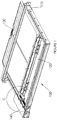
- Fig. 1 shows a vehicle access ramp unit 100 having a support frame 110 defining a storage space 120 for a platform 130 when the platform is in the retracted position.
- the access ramp is also provided with a motor located in a side housing 140.
- the access ramp 100 is supplied for fitting to a vehicle and will be fitted just under the vehicle entrance floor. In this view, the vehicle floor (or the top cover of the access ramp unit) is not shown for clarity, so that the components can be seen.
- Fig. 2 shows an enlarged view of the circled area C in Fig. 1 , showing more details of the platform extension and retraction mechanism.
- the mechanism comprises a lead screw 150, internally-threaded platform mounting 160 and yoke 180.
- Yoke 180 is connected to platform 130 by means of platform frame section 131. Through rotation of the lead screw 150 by the motor, the mounting 160, yoke 180 and therefore platform 130 can be moved backwards and forwards in the direction of the double-headed arrow to extend or retract the platform.
- a similar platform extension and retraction mechanism is provided on the other side of the support frame 110.
- Lock control cable 190 is also shown in this figure, and will be discussed later.
- Mounting 160 comprises a housing 161 having a generally cuboid shape with a cylindrical passage 162 through the centre.
- An internally-threaded insert 170 fits into passage 162 and in the absence of any restraining mechanism is able to rotate within the passage about the axis of the passage.
- insert 170 is prevented from lateral movement along the axis relative to the mounting by means of circlip plate 163 which is secured to the rear side of housing 161 and engages groove 171 of the insert 170.
- Insert 170 has a generally cylindrical body with a cylindrical passage 172 which is provided with an internal thread 173. When assembled, the lead screw, housing passage 162 and insert passage 172 are co-axial.
- the insert also has a flange 174, on the inner face of which is provided a plurality of recesses 175.
- Recesses 175 engage with projection or "bullet” 164 which is sprung-loaded by means of spring 165 and locates in bore 166, offset to the side of the main passage 162.
- Bullet or projection 164 acts as a lock, as will be described below.
- Yoke 180 is also shown in Fig. 3 , and a degree of relative movement between yoke 180 and housing 160 is possible by means of pins 167 cooperating with round holes 181.
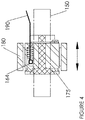
- Fig. 4 shows the assembled mechanism in cross-section.
- This figure also shows lock control cable 190 which is connected to projection 164.
- the spring 165 urges projection 164 into engagement with a recess 175 in the flange of the insert.
- the projection extends from the recess into the bore 166, it serves to lock the housing and insert together and insert 170 is not able to rotate relative to the housing. Therefore, rotation of the lead screw 150 will cause the mounting 160 to move backwards or forwards in the direction of the double-headed arrow to extend or retract the platform.
- a force can be applied to projection 164 by the cable 190 to retract the projection against the force of the spring 165, so that the insert is not locked to the housing and is therefore free to rotate relative to the housing.
- a force can be applied to the platform 130 in either direction of the arrow to move the platform in or out by hand, which causes the housing to travel along the lead screw while the insert rotates around the lead screw thread relative to the housing.
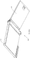
- the lock release mechanism is shown in more detail in Figs. 5 and 6 .
- Two Bowden-type cables 190 are shown, which are connected to projections 164 in mountings 160 on each side of the ramp unit 100.
- the outer ends of the cables are connected to handle 191 which is located on the underside of platform 130.
- handle 191 By gripping the platform and squeezing handle 191, projections 164 are released from engagement with the inserts 170 and the platform can be manually extended or retracted as required. Releasing the handle re-engages the projections with the inserts and the platform is then held in the new position (e.g. extended or retracted) by the extension and retraction mechanism.
Landscapes
- Engineering & Computer Science (AREA)
- Mechanical Engineering (AREA)
- General Engineering & Computer Science (AREA)
- Health & Medical Sciences (AREA)
- Public Health (AREA)
- Transportation (AREA)
- Life Sciences & Earth Sciences (AREA)
- Animal Behavior & Ethology (AREA)
- General Health & Medical Sciences (AREA)
- Veterinary Medicine (AREA)
- Lock And Its Accessories (AREA)
- Passenger Equipment (AREA)
- Transmission Devices (AREA)
- Mechanical Control Devices (AREA)
Claims (6)
- Rampe d'accès pour véhicule (100) comprenant :un cadre de support (110) définissant un espace de stockage (120) ;une plateforme (130) mobile d'une position rétractée dans laquelle la plateforme est sensiblement au sein de l'espace de stockage à une position étendue dans laquelle la plateforme s'étend depuis l'espace de stockage ; etune vis mère (150) ayant un axe longitudinal et un filet externe qui est montée rotative dans l'espace de stockage sur le cadre de support (110) et qui s'étend dans la direction de déplacement de la plateforme, sur laquelle la plateforme (130) est montée au moyen d'une monture filetée à l'intérieur (160) de sorte que, lorsque la vis mère tourne, la monture (160) circule le long de la vis mère et déplace la plateforme vers la position étendue ou la position rétractée,caractérisée en ce que la monture (160) comprend un logement (161), un insert fileté à l'intérieur (170) monté rotatif dans le logement et s'engageant avec la vis mère, et un verrou, le verrou ayant une position verrouillée dans laquelle l'insert (170) est fixé en rotation par rapport au logement (161) et une position libérée dans laquelle l'insert est capable de tourner dans le logement, dans laquelle le verrou comprend une saillie (164) montée rétractable dans le logement (161) qui, dans la position verrouillée, s'engage avec un ou plusieurs évidements (175) prévus sur une collerette (174) sur l'insert (170) afin de verrouiller le logement et l'insert ensemble, et qui est rétractée dans une direction parallèle à l'axe longitudinal de la vis mère à la position libérée afin de permettre à l'insert de tourner par rapport au logement, et dans laquelle la saillie (164) est poussée vers la position verrouillée au moyen d'un ressort (165).
- Rampe d'accès pour véhicule selon la revendication 1, dans laquelle le logement (161) a un passage cylindrique (162) dans lequel l'insert (170) est situé et l'insert a un passage cylindrique (172) qui est fileté à l'intérieur et dans lequel la vis mère est située, et dans laquelle la vis mère (150), le passage de logement (162) et le passage d'insert (172) sont coaxiaux.
- Rampe d'accès pour véhicule selon l'une quelconque des revendications précédentes, comprenant en outre un mécanisme de commande de verrou pour déplacer le verrou entre les positions verrouillée et libérée, dans laquelle le mécanisme de commande de verrou comprend une poignée de commande (191) reliée au verrou au moyen d'un câble (190).
- Rampe d'accès pour véhicule selon la revendication 3, comprenant en outre deux vis mères (150), deux montures de plateforme (160) et deux verrous, et dans laquelle le mécanisme de commande de verrou libère les deux verrous sensiblement simultanément.
- Rampe d'accès pour véhicule selon l'une quelconque des revendications précédentes, dans laquelle la plateforme est montée sur le logement via un étrier (180).
- Véhicule comportant la rampe d'accès pour véhicule de l'une quelconque des revendications précédentes.
Priority Applications (1)
| Application Number | Priority Date | Filing Date | Title |
|---|---|---|---|
| PL17182639T PL3276207T3 (pl) | 2016-07-26 | 2017-07-21 | Mechanizm śruby pociągowej |
Applications Claiming Priority (1)
| Application Number | Priority Date | Filing Date | Title |
|---|---|---|---|
| GB1612933.0A GB2552509A (en) | 2016-07-26 | 2016-07-26 | Lead screw mechanism |
Publications (2)
| Publication Number | Publication Date |
|---|---|
| EP3276207A1 EP3276207A1 (fr) | 2018-01-31 |
| EP3276207B1 true EP3276207B1 (fr) | 2021-02-17 |
Family
ID=56894601
Family Applications (1)
| Application Number | Title | Priority Date | Filing Date |
|---|---|---|---|
| EP17182639.9A Active EP3276207B1 (fr) | 2016-07-26 | 2017-07-21 | Mécanisme de vis à rouleaux |
Country Status (7)
| Country | Link |
|---|---|
| EP (1) | EP3276207B1 (fr) |
| CN (1) | CN107650804B (fr) |
| ES (1) | ES2871068T3 (fr) |
| GB (1) | GB2552509A (fr) |
| HU (1) | HUE055071T2 (fr) |
| PL (1) | PL3276207T3 (fr) |
| PT (1) | PT3276207T (fr) |
Families Citing this family (1)
| Publication number | Priority date | Publication date | Assignee | Title |
|---|---|---|---|---|
| CN112550333A (zh) * | 2020-12-07 | 2021-03-26 | 湖南智鑫智能科技有限公司 | 一种电动平车上的多功能固定结构 |
Family Cites Families (6)
| Publication number | Priority date | Publication date | Assignee | Title |
|---|---|---|---|---|
| WO1980001266A1 (fr) * | 1978-12-19 | 1980-06-26 | D Manning | Rampe d'entree pour vehicules |
| FR2605075B1 (fr) * | 1986-10-13 | 1989-01-27 | Rockwell Cim | Systeme de verrouillage d'un dispositif lineaire de reglage rapide et de blocage d'une piece mobile par rapport a une piece fixe |
| FR2756267B1 (fr) * | 1996-11-26 | 1999-01-08 | Lohr Ind | Bloc de translation a ecrou debrayable pour ensembles de levage a vis |
| GB9821674D0 (en) * | 1998-10-05 | 1998-12-02 | Intellitec Mv Ltd | Ramp |
| WO2008040138A1 (fr) * | 2006-10-03 | 2008-04-10 | Kaba Gilgen Ag | Dispositif d'enjambement pour quais de gare |
| ES2550369B1 (es) * | 2014-05-05 | 2016-07-21 | Mespack, Sl | Dispositivo automático de cambio de formato para máquina horizontal automática formadora y llenadora de envases flexibles |
-
2016
- 2016-07-26 GB GB1612933.0A patent/GB2552509A/en not_active Withdrawn
-
2017
- 2017-07-21 ES ES17182639T patent/ES2871068T3/es active Active
- 2017-07-21 HU HUE17182639A patent/HUE055071T2/hu unknown
- 2017-07-21 PT PT171826399T patent/PT3276207T/pt unknown
- 2017-07-21 PL PL17182639T patent/PL3276207T3/pl unknown
- 2017-07-21 EP EP17182639.9A patent/EP3276207B1/fr active Active
- 2017-07-26 CN CN201710619545.4A patent/CN107650804B/zh active Active
Non-Patent Citations (1)
| Title |
|---|
| None * |
Also Published As
| Publication number | Publication date |
|---|---|
| CN107650804A (zh) | 2018-02-02 |
| PL3276207T3 (pl) | 2021-08-09 |
| EP3276207A1 (fr) | 2018-01-31 |
| GB2552509A (en) | 2018-01-31 |
| HUE055071T2 (hu) | 2021-10-28 |
| ES2871068T3 (es) | 2021-10-28 |
| GB201612933D0 (en) | 2016-09-07 |
| PT3276207T (pt) | 2021-05-21 |
| CN107650804B (zh) | 2022-07-29 |
Similar Documents
| Publication | Publication Date | Title |
|---|---|---|
| US9234378B2 (en) | Power tailgate system | |
| EP3237254A1 (fr) | Marchepied avec fonction de levage et de rampe | |
| EP3194202B1 (fr) | Dispositif motorisé de puissance à réglage rapide | |
| JP5938463B2 (ja) | プラグドアロック装置及びプラグドアシステム | |
| DE102017204914A1 (de) | Kraft-Schwenktür-Betätigungsglied mit gelenkigem Verbindungsmechanismus | |
| EP1953314B1 (fr) | Système de fermeture électromécanique | |
| DE60317192T2 (de) | Mit totgang und zwei scheiben versehene sitzneigungsverstellanordnung | |
| DE602005003162T2 (de) | Feststellbremse | |
| DE69300308T2 (de) | Schwenkbetätigungsvorrichtung einer Trittstufenanordnung für Fahrzeuge. | |
| EP3397829B1 (fr) | Ensemble poignée de porte d'un véhicule automobile | |
| DE60021856T2 (de) | Kraftangetriebene türverriegelungsvorrichtung | |
| EP3276207B1 (fr) | Mécanisme de vis à rouleaux | |
| DE102019207209A1 (de) | Fahrzeugbremsvorrichtung | |
| WO2011148691A1 (fr) | Dispositif coulissant à commande électrique | |
| EP2998182A1 (fr) | Unite d'entrainement pour une marche d'un vehicule sur rails, module de marche et vehicule sur rails dote d'un module de marche | |
| EP2766240B1 (fr) | Véhicule ferroviaire pour le transport de voyageurs | |
| DE102009021655A1 (de) | Kraftfahrzeug mit Haltegriff | |
| US6729072B1 (en) | Integral latch and drive system for a powered sliding door | |
| DE10305590B4 (de) | Elektromagnetische Federdruckbremse | |
| DE102010060192A1 (de) | Befestigungsvorrichtung und Fahrzeug | |
| WO2005102760A1 (fr) | Systeme d'entrainement de moyeu pour petit vehicule | |
| WO2024222991A1 (fr) | Connecteur enfichable de charge pour véhicules électriques et hybrides | |
| US11142226B2 (en) | Low profile gap mitigation device | |
| CN112154249B (zh) | 车门的电动控制装置 | |
| DE102007047349A1 (de) | Verladevorrichtung |
Legal Events
| Date | Code | Title | Description |
|---|---|---|---|
| PUAI | Public reference made under article 153(3) epc to a published international application that has entered the european phase |
Free format text: ORIGINAL CODE: 0009012 |
|
| STAA | Information on the status of an ep patent application or granted ep patent |
Free format text: STATUS: THE APPLICATION HAS BEEN PUBLISHED |
|
| AK | Designated contracting states |
Kind code of ref document: A1 Designated state(s): AL AT BE BG CH CY CZ DE DK EE ES FI FR GB GR HR HU IE IS IT LI LT LU LV MC MK MT NL NO PL PT RO RS SE SI SK SM TR |
|
| AX | Request for extension of the european patent |
Extension state: BA ME |
|
| STAA | Information on the status of an ep patent application or granted ep patent |
Free format text: STATUS: REQUEST FOR EXAMINATION WAS MADE |
|
| 17P | Request for examination filed |
Effective date: 20180613 |
|
| RBV | Designated contracting states (corrected) |
Designated state(s): AL AT BE BG CH CY CZ DE DK EE ES FI FR GB GR HR HU IE IS IT LI LT LU LV MC MK MT NL NO PL PT RO RS SE SI SK SM TR |
|
| STAA | Information on the status of an ep patent application or granted ep patent |
Free format text: STATUS: EXAMINATION IS IN PROGRESS |
|
| 17Q | First examination report despatched |
Effective date: 20200207 |
|
| GRAP | Despatch of communication of intention to grant a patent |
Free format text: ORIGINAL CODE: EPIDOSNIGR1 |
|
| STAA | Information on the status of an ep patent application or granted ep patent |
Free format text: STATUS: GRANT OF PATENT IS INTENDED |
|
| INTG | Intention to grant announced |
Effective date: 20200909 |
|
| GRAS | Grant fee paid |
Free format text: ORIGINAL CODE: EPIDOSNIGR3 |
|
| GRAA | (expected) grant |
Free format text: ORIGINAL CODE: 0009210 |
|
| STAA | Information on the status of an ep patent application or granted ep patent |
Free format text: STATUS: THE PATENT HAS BEEN GRANTED |
|
| AK | Designated contracting states |
Kind code of ref document: B1 Designated state(s): AL AT BE BG CH CY CZ DE DK EE ES FI FR GB GR HR HU IE IS IT LI LT LU LV MC MK MT NL NO PL PT RO RS SE SI SK SM TR |
|
| REG | Reference to a national code |
Ref country code: GB Ref legal event code: FG4D |
|
| REG | Reference to a national code |
Ref country code: CH Ref legal event code: EP |
|
| REG | Reference to a national code |
Ref country code: DE Ref legal event code: R096 Ref document number: 602017032528 Country of ref document: DE |
|
| REG | Reference to a national code |
Ref country code: AT Ref legal event code: REF Ref document number: 1361890 Country of ref document: AT Kind code of ref document: T Effective date: 20210315 |
|
| REG | Reference to a national code |
Ref country code: IE Ref legal event code: FG4D |
|
| REG | Reference to a national code |
Ref country code: PT Ref legal event code: SC4A Ref document number: 3276207 Country of ref document: PT Date of ref document: 20210521 Kind code of ref document: T Free format text: AVAILABILITY OF NATIONAL TRANSLATION Effective date: 20210514 |
|
| REG | Reference to a national code |
Ref country code: NL Ref legal event code: FP |
|
| REG | Reference to a national code |
Ref country code: LT Ref legal event code: MG9D |
|
| PG25 | Lapsed in a contracting state [announced via postgrant information from national office to epo] |
Ref country code: BG Free format text: LAPSE BECAUSE OF FAILURE TO SUBMIT A TRANSLATION OF THE DESCRIPTION OR TO PAY THE FEE WITHIN THE PRESCRIBED TIME-LIMIT Effective date: 20210517 Ref country code: LT Free format text: LAPSE BECAUSE OF FAILURE TO SUBMIT A TRANSLATION OF THE DESCRIPTION OR TO PAY THE FEE WITHIN THE PRESCRIBED TIME-LIMIT Effective date: 20210217 Ref country code: FI Free format text: LAPSE BECAUSE OF FAILURE TO SUBMIT A TRANSLATION OF THE DESCRIPTION OR TO PAY THE FEE WITHIN THE PRESCRIBED TIME-LIMIT Effective date: 20210217 Ref country code: GR Free format text: LAPSE BECAUSE OF FAILURE TO SUBMIT A TRANSLATION OF THE DESCRIPTION OR TO PAY THE FEE WITHIN THE PRESCRIBED TIME-LIMIT Effective date: 20210518 Ref country code: HR Free format text: LAPSE BECAUSE OF FAILURE TO SUBMIT A TRANSLATION OF THE DESCRIPTION OR TO PAY THE FEE WITHIN THE PRESCRIBED TIME-LIMIT Effective date: 20210217 Ref country code: NO Free format text: LAPSE BECAUSE OF FAILURE TO SUBMIT A TRANSLATION OF THE DESCRIPTION OR TO PAY THE FEE WITHIN THE PRESCRIBED TIME-LIMIT Effective date: 20210517 |
|
| REG | Reference to a national code |
Ref country code: AT Ref legal event code: MK05 Ref document number: 1361890 Country of ref document: AT Kind code of ref document: T Effective date: 20210217 |
|
| PG25 | Lapsed in a contracting state [announced via postgrant information from national office to epo] |
Ref country code: SE Free format text: LAPSE BECAUSE OF FAILURE TO SUBMIT A TRANSLATION OF THE DESCRIPTION OR TO PAY THE FEE WITHIN THE PRESCRIBED TIME-LIMIT Effective date: 20210217 Ref country code: LV Free format text: LAPSE BECAUSE OF FAILURE TO SUBMIT A TRANSLATION OF THE DESCRIPTION OR TO PAY THE FEE WITHIN THE PRESCRIBED TIME-LIMIT Effective date: 20210217 Ref country code: RS Free format text: LAPSE BECAUSE OF FAILURE TO SUBMIT A TRANSLATION OF THE DESCRIPTION OR TO PAY THE FEE WITHIN THE PRESCRIBED TIME-LIMIT Effective date: 20210217 |
|
| PG25 | Lapsed in a contracting state [announced via postgrant information from national office to epo] |
Ref country code: IS Free format text: LAPSE BECAUSE OF FAILURE TO SUBMIT A TRANSLATION OF THE DESCRIPTION OR TO PAY THE FEE WITHIN THE PRESCRIBED TIME-LIMIT Effective date: 20210617 |
|
| REG | Reference to a national code |
Ref country code: ES Ref legal event code: FG2A Ref document number: 2871068 Country of ref document: ES Kind code of ref document: T3 Effective date: 20211028 Ref country code: HU Ref legal event code: AG4A Ref document number: E055071 Country of ref document: HU |
|
| PG25 | Lapsed in a contracting state [announced via postgrant information from national office to epo] |
Ref country code: SM Free format text: LAPSE BECAUSE OF FAILURE TO SUBMIT A TRANSLATION OF THE DESCRIPTION OR TO PAY THE FEE WITHIN THE PRESCRIBED TIME-LIMIT Effective date: 20210217 Ref country code: AT Free format text: LAPSE BECAUSE OF FAILURE TO SUBMIT A TRANSLATION OF THE DESCRIPTION OR TO PAY THE FEE WITHIN THE PRESCRIBED TIME-LIMIT Effective date: 20210217 Ref country code: CZ Free format text: LAPSE BECAUSE OF FAILURE TO SUBMIT A TRANSLATION OF THE DESCRIPTION OR TO PAY THE FEE WITHIN THE PRESCRIBED TIME-LIMIT Effective date: 20210217 Ref country code: EE Free format text: LAPSE BECAUSE OF FAILURE TO SUBMIT A TRANSLATION OF THE DESCRIPTION OR TO PAY THE FEE WITHIN THE PRESCRIBED TIME-LIMIT Effective date: 20210217 |
|
| REG | Reference to a national code |
Ref country code: DE Ref legal event code: R097 Ref document number: 602017032528 Country of ref document: DE |
|
| PG25 | Lapsed in a contracting state [announced via postgrant information from national office to epo] |
Ref country code: SK Free format text: LAPSE BECAUSE OF FAILURE TO SUBMIT A TRANSLATION OF THE DESCRIPTION OR TO PAY THE FEE WITHIN THE PRESCRIBED TIME-LIMIT Effective date: 20210217 Ref country code: RO Free format text: LAPSE BECAUSE OF FAILURE TO SUBMIT A TRANSLATION OF THE DESCRIPTION OR TO PAY THE FEE WITHIN THE PRESCRIBED TIME-LIMIT Effective date: 20210217 Ref country code: DK Free format text: LAPSE BECAUSE OF FAILURE TO SUBMIT A TRANSLATION OF THE DESCRIPTION OR TO PAY THE FEE WITHIN THE PRESCRIBED TIME-LIMIT Effective date: 20210217 |
|
| PGFP | Annual fee paid to national office [announced via postgrant information from national office to epo] |
Ref country code: TR Payment date: 20210716 Year of fee payment: 5 Ref country code: HU Payment date: 20210802 Year of fee payment: 5 Ref country code: PL Payment date: 20210712 Year of fee payment: 5 |
|
| PLBE | No opposition filed within time limit |
Free format text: ORIGINAL CODE: 0009261 |
|
| STAA | Information on the status of an ep patent application or granted ep patent |
Free format text: STATUS: NO OPPOSITION FILED WITHIN TIME LIMIT |
|
| PGFP | Annual fee paid to national office [announced via postgrant information from national office to epo] |
Ref country code: PT Payment date: 20210708 Year of fee payment: 5 |
|
| 26N | No opposition filed |
Effective date: 20211118 |
|
| PG25 | Lapsed in a contracting state [announced via postgrant information from national office to epo] |
Ref country code: AL Free format text: LAPSE BECAUSE OF FAILURE TO SUBMIT A TRANSLATION OF THE DESCRIPTION OR TO PAY THE FEE WITHIN THE PRESCRIBED TIME-LIMIT Effective date: 20210217 |
|
| PG25 | Lapsed in a contracting state [announced via postgrant information from national office to epo] |
Ref country code: SI Free format text: LAPSE BECAUSE OF FAILURE TO SUBMIT A TRANSLATION OF THE DESCRIPTION OR TO PAY THE FEE WITHIN THE PRESCRIBED TIME-LIMIT Effective date: 20210217 |
|
| REG | Reference to a national code |
Ref country code: CH Ref legal event code: PL |
|
| PG25 | Lapsed in a contracting state [announced via postgrant information from national office to epo] |
Ref country code: MC Free format text: LAPSE BECAUSE OF FAILURE TO SUBMIT A TRANSLATION OF THE DESCRIPTION OR TO PAY THE FEE WITHIN THE PRESCRIBED TIME-LIMIT Effective date: 20210217 |
|
| REG | Reference to a national code |
Ref country code: BE Ref legal event code: MM Effective date: 20210731 |
|
| PG25 | Lapsed in a contracting state [announced via postgrant information from national office to epo] |
Ref country code: LI Free format text: LAPSE BECAUSE OF NON-PAYMENT OF DUE FEES Effective date: 20210731 Ref country code: CH Free format text: LAPSE BECAUSE OF NON-PAYMENT OF DUE FEES Effective date: 20210731 |
|
| PG25 | Lapsed in a contracting state [announced via postgrant information from national office to epo] |
Ref country code: IS Free format text: LAPSE BECAUSE OF FAILURE TO SUBMIT A TRANSLATION OF THE DESCRIPTION OR TO PAY THE FEE WITHIN THE PRESCRIBED TIME-LIMIT Effective date: 20210617 Ref country code: LU Free format text: LAPSE BECAUSE OF NON-PAYMENT OF DUE FEES Effective date: 20210721 |
|
| PG25 | Lapsed in a contracting state [announced via postgrant information from national office to epo] |
Ref country code: IE Free format text: LAPSE BECAUSE OF NON-PAYMENT OF DUE FEES Effective date: 20210721 Ref country code: BE Free format text: LAPSE BECAUSE OF NON-PAYMENT OF DUE FEES Effective date: 20210731 |
|
| PG25 | Lapsed in a contracting state [announced via postgrant information from national office to epo] |
Ref country code: PT Free format text: LAPSE BECAUSE OF NON-PAYMENT OF DUE FEES Effective date: 20230123 |
|
| PG25 | Lapsed in a contracting state [announced via postgrant information from national office to epo] |
Ref country code: HU Free format text: LAPSE BECAUSE OF NON-PAYMENT OF DUE FEES Effective date: 20220722 |
|
| PG25 | Lapsed in a contracting state [announced via postgrant information from national office to epo] |
Ref country code: CY Free format text: LAPSE BECAUSE OF FAILURE TO SUBMIT A TRANSLATION OF THE DESCRIPTION OR TO PAY THE FEE WITHIN THE PRESCRIBED TIME-LIMIT Effective date: 20210217 |
|
| PG25 | Lapsed in a contracting state [announced via postgrant information from national office to epo] |
Ref country code: MK Free format text: LAPSE BECAUSE OF FAILURE TO SUBMIT A TRANSLATION OF THE DESCRIPTION OR TO PAY THE FEE WITHIN THE PRESCRIBED TIME-LIMIT Effective date: 20210217 |
|
| PG25 | Lapsed in a contracting state [announced via postgrant information from national office to epo] |
Ref country code: PL Free format text: LAPSE BECAUSE OF NON-PAYMENT OF DUE FEES Effective date: 20220721 |
|
| PG25 | Lapsed in a contracting state [announced via postgrant information from national office to epo] |
Ref country code: MT Free format text: LAPSE BECAUSE OF FAILURE TO SUBMIT A TRANSLATION OF THE DESCRIPTION OR TO PAY THE FEE WITHIN THE PRESCRIBED TIME-LIMIT Effective date: 20210217 |
|
| PGFP | Annual fee paid to national office [announced via postgrant information from national office to epo] |
Ref country code: NL Payment date: 20250730 Year of fee payment: 9 |
|
| PGFP | Annual fee paid to national office [announced via postgrant information from national office to epo] |
Ref country code: ES Payment date: 20250826 Year of fee payment: 9 |
|
| PGFP | Annual fee paid to national office [announced via postgrant information from national office to epo] |
Ref country code: DE Payment date: 20250730 Year of fee payment: 9 |
|
| PGFP | Annual fee paid to national office [announced via postgrant information from national office to epo] |
Ref country code: IT Payment date: 20250730 Year of fee payment: 9 |
|
| PGFP | Annual fee paid to national office [announced via postgrant information from national office to epo] |
Ref country code: GB Payment date: 20250728 Year of fee payment: 9 |
|
| PGFP | Annual fee paid to national office [announced via postgrant information from national office to epo] |
Ref country code: FR Payment date: 20250730 Year of fee payment: 9 |