EP3281868A1 - Pneu d'aéronef - Google Patents
Pneu d'aéronef Download PDFInfo
- Publication number
- EP3281868A1 EP3281868A1 EP17180876.9A EP17180876A EP3281868A1 EP 3281868 A1 EP3281868 A1 EP 3281868A1 EP 17180876 A EP17180876 A EP 17180876A EP 3281868 A1 EP3281868 A1 EP 3281868A1
- Authority
- EP
- European Patent Office
- Prior art keywords
- tire body
- legs
- pair
- tire
- protrusion
- Prior art date
- Legal status (The legal status is an assumption and is not a legal conclusion. Google has not performed a legal analysis and makes no representation as to the accuracy of the status listed.)
- Granted
Links
Images


Classifications
-
- B—PERFORMING OPERATIONS; TRANSPORTING
- B64—AIRCRAFT; AVIATION; COSMONAUTICS
- B64C—AEROPLANES; HELICOPTERS
- B64C25/00—Alighting gear
- B64C25/32—Alighting gear characterised by elements which contact the ground or similar surface
- B64C25/34—Alighting gear characterised by elements which contact the ground or similar surface wheeled type, e.g. multi-wheeled bogies
- B64C25/36—Arrangements or adaptations of wheels, tyres or axles in general
-
- B—PERFORMING OPERATIONS; TRANSPORTING
- B64—AIRCRAFT; AVIATION; COSMONAUTICS
- B64C—AEROPLANES; HELICOPTERS
- B64C25/00—Alighting gear
- B64C25/32—Alighting gear characterised by elements which contact the ground or similar surface
- B64C25/40—Alighting gear characterised by elements which contact the ground or similar surface the elements being rotated before touch-down
-
- B—PERFORMING OPERATIONS; TRANSPORTING
- B60—VEHICLES IN GENERAL
- B60C—VEHICLE TYRES; TYRE INFLATION; TYRE CHANGING; CONNECTING VALVES TO INFLATABLE ELASTIC BODIES IN GENERAL; DEVICES OR ARRANGEMENTS RELATED TO TYRES
- B60C13/00—Tyre sidewalls; Protecting, decorating, marking, or the like, thereof
- B60C13/02—Arrangement of grooves or ribs
-
- B—PERFORMING OPERATIONS; TRANSPORTING
- B60—VEHICLES IN GENERAL
- B60C—VEHICLE TYRES; TYRE INFLATION; TYRE CHANGING; CONNECTING VALVES TO INFLATABLE ELASTIC BODIES IN GENERAL; DEVICES OR ARRANGEMENTS RELATED TO TYRES
- B60C19/00—Tyre parts or constructions not otherwise provided for
- B60C19/001—Tyres requiring an asymmetric or a special mounting
-
- B—PERFORMING OPERATIONS; TRANSPORTING
- B64—AIRCRAFT; AVIATION; COSMONAUTICS
- B64C—AEROPLANES; HELICOPTERS
- B64C25/00—Alighting gear
- B64C25/001—Devices not provided for in the groups B64C25/02 - B64C25/68
-
- B—PERFORMING OPERATIONS; TRANSPORTING
- B60—VEHICLES IN GENERAL
- B60C—VEHICLE TYRES; TYRE INFLATION; TYRE CHANGING; CONNECTING VALVES TO INFLATABLE ELASTIC BODIES IN GENERAL; DEVICES OR ARRANGEMENTS RELATED TO TYRES
- B60C2200/00—Tyres specially adapted for particular applications
- B60C2200/02—Tyres specially adapted for particular applications for aircrafts
Definitions
- the present invention relates to an aircraft tire which rotates by receiving flight wind pressure, and more particularly to an aircraft tire having a speed control function.
- An ultra-high-capacity aircraft such as Airbus A380 weighs 560 tons, and its big body must be supported by two tires at a nose landing gear and twenty tires at a main landing gear, that is, twenty two tires in total.
- the tire used for such an aircraft has an internal pressure six or more times higher than a tire for a passenger car, so that measures such as improving the material and surface structure of an aircraft tire itself are taken.
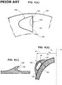
- a side of a tire body 100 is mounted with, on its outer peripheral side, a plurality of windmill vanes 101 oriented in the same direction.
- each of the vanes 101 has, with respect to an airframe, a streamlined front portion for reduced wind resistance and a rear portion having a concave surface for increased wind resistance.
- the vane 101 described in Unexamined Japanese Utility Model Publication No . H07-31600 includes a recess102 that is formed by denting the vane's end to have the rear portion with the concave surface.
- a pressure receiving surface 106 that receives the flight wind pressure is formed of an internal surface of the recess 102, respective end faces of lateral portions 103, 104 with respect to the recess 102, and an end face of an upper portion 105 with respect to the recess 102.
- the vane 101 is otherwise solid, so that structurally, it is difficult to cause the lateral portions 103, 104 to fall over in a direction from a center of the tire body 100 toward an outer periphery of the tire body 100. Moreover, a center of gravity G of the upper portion 105 is positioned between the lateral portions 103, 104.
- the recess 102 cannot be narrowed. Accordingly, an area of the pressure receiving surface 106 cannot be reduced.
- the vanes 101 provided on the side of the tire body 100 in Unexamined Japanese Utility Model Publication No. H07-31600 cannot prevent rotating speed of the wheel from becoming too high when the wheel is rotated before the touchdown by the action of the flight wind pressure received by the vanes 101. Consequently, shock such as to accelerate the aircraft at the touchdown may problematically be caused.
- the applicant of the present invention has already proposed an aircraft tire having a function of preventing rotating speed of a wheel from becoming too high during rotation of the wheel before touchdown (refer to Japanese Patent No. 5,763,818 ).
- protrusions each having a pressure receiving surface that receives flight wind pressure are protrusively provided on a side of a tire body
- the protrusion has a hollow structure into which a weight is inserted.
- the protrusion is deformed by centrifugal force that acts on the weight during rotation of the wheel before touchdown.
- An area of the pressure receiving surface of the protrusion is thus reduced for suppression of an acceleration effect, whereby the rotating speed of the wheel is prevented from becoming too high.
- the present invention has been made in view of the above problems, and an object of the present invention is to provide an aircraft tire capable of accomplishing, with a simple structure, a function of preventing rotating speed of a wheel from becoming too high when the wheel is rotated before touchdown by the action of flight wind pressure received by protrusions provided protrusively on a side of a tire body
- an aircraft tire according to the present invention includes: a tire body forming an outer peripheral part of an aircraft wheel; and a protrusion that is provided protrusively on a side of the tire body, includes at one end thereof a pressure receiving surface configured to receive flight wind pressure and has a streamline shape tapering toward another end of the protrusion along a circumference of the tire body, for rotation of the aircraft wheel before touchdown in a direction in which the aircraft wheel rotates during a landing roll, through the action of the flight wind pressure received by the pressure receiving surface, wherein the protrusion includes:
- a thickness of the weight portion in a protruding direction of the protrusion be greater than a thickness of each of the pair of legs along the radius of the tire body (a second aspect of the present invention).
- the protrusion be provided with a drain hole allowing the hollow part to communicate exteriorly (a third aspect of the present invention).
- the hollow part is provided to extend between the one end and the other end of the protrusion, so that there is no resistance between the pair of legs.
- the pair of legs structurally falls over easily in the direction from the center of the tire body toward the outer periphery of the tire body
- the weight portion supported by the pair of legs With the weight portion supported by the pair of legs to have its center of gravity positioned outwardly of the respective horizontal positions of the pair of legs with respect to the center line widthwise of the tire body, a bending moment can act effectively on the pair of legs for causing the legs to fall over in the direction from the center of the tire body toward the outer periphery of the tire body as a result of being effected by the centrifugal force that acts on the weight portion during rotation of the wheel before touchdown.
- the hollow part is narrowed, whereby the area of the pressure receiving surface can be reduced. With the area of the pressure receiving surface reduced, an acceleration effect is suppressed, whereby rotating speed of the wheel can be prevented from becoming too high.
- the thickness of the weight portion in the protruding direction of the protrusion being greater than the thickness of each of the pair of legs along the radius of the tire body, increased centrifugal force can act on the weight portion, thereby causing, without fail, the pair of legs to fall over in the direction from the center of the tire body toward the outer periphery of the tire body
- the protrusion is provided with the drain hole allowing the hollow part to communicate exteriorly. In this way, even when, for example, rain water tends to collect in the hollow part, the rain water can be discharged from the drain hole, whereby the malfunction can be prevented.
- the aircraft wheel 1 shown in FIGS. 1(a) to 1(c) is formed by mounting the aircraft tire 3 to a wheel 2 and rotates during a landing roll in a direction of arrow R in the drawing with respect to an aircraft flight direction of arrow D in the drawing.
- the aircraft tire 3 includes a tire body 4 forming an outer peripheral part of the wheel 1, and a plurality of protrusions 5 that is formed integrally with the tire body 4 for receiving flight wind pressure (indicated by arrow P in FIG. 1(a) ).
- the protrusions 5 are circumferentially provided in a protrusive manner at predetermined pitches on an outer peripheral side of a side of the tire body 4.
- Each of the protrusions 5 includes at one end thereof a pressure receiving surface 10 configured to receive the flight wind pressure and has such a streamline shape that it narrows to taper toward another end thereof along a circumference of the tire body 4 while its protruding height above the side of the tire body 4 reduces, heading toward the other end along the circumference of the tire body 4.
- a streamline shape does not cause air turbulence and can prevent abnormal noise. It is to be noted that the streamline shape can appropriately be made longer or shorter than the one shown in this exemplary embodiment.
- each of the protrusions 5 includes a pair of legs 11, 12, a weight portion 13, and a hollow part 14.
- the pair of legs 11, 12 is erected on the side of the tire body 4 so as to protrude from the outer peripheral side of the tire body's side in spaced relation along a radius of the tire body 4 (along a direction from a center of the tire body 4 toward an outer periphery of the tire body 4).
- the pair of legs 11, 12 extends along the circumference of the tire body 4. Spacing between the pair of legs 11, 12 reduces, heading from the one end of the protrusion 5 toward the other end of the protrusion 5 along the circumference of the tire body 4. As shown in FIG.
- the pair of legs 11, 12 is disposed in opposed relation so that its protruding height above the side of the tire body 4 reduces, heading from the one end of the protrusion 5 toward the other end of the protrusion 5 along the circumference of the tire body 4.
- the weight portion 13 is semielliptical or mountain-shaped, tapering in a protruding direction of the protrusion 5.
- a thickness of this weight portion 13 in the protruding direction of the protrusion 5 is sufficiently greater than a thickness of each of the pair of legs 11, 12 along the radius of the tire body 4. In this way, increased centrifugal force can act on the weight portion 13, thereby causing, without fail, the pair of legs 11, 12 to fall over in the direction from the center of the tire body 4 toward the outer periphery of the tire body 4.
- the weight portion 13 is supported by the pair of legs 11, 12 to have its center of gravity G positioned outwardly of respective horizontal positions of the pair of legs 11, 12 with respect to a center line S widthwise of the tire body 4.
- the weight portion 13 is supported by the pair of legs 11, 12 so that when X G is a horizontal distance between the center line S and the center of gravity G of the weight portion 13 with X 1 being a horizontal distance between the center line S and a heightwise protruding end of the leg 11 along the outer periphery of the tire body 4 and X 2 being a horizontal distance between the center line S and a heightwise protruding end of the leg 12 along the center of the tire body 4, X G > X 2 > X 1 in a state of FIG.
- the hollow part 14 is defined by the side of the tire body 4, the pair of legs 11, 12, and the weight portion 13 and extends between the one end of the protrusion 5 and the other end of the protrusion 5 as shown in FIGS. 1(b) and 1(c) .
- the hollow part 14 provided to extend between the one end and the other end of the protrusion 5, there is no resistance between the pair of legs 11, 12.
- the pair of legs 11, 12 structurally falls over easily in the direction from the center of the tire body 4 toward the outer periphery of the tire body 4.
- the pressure receiving surface 10 of the protrusion 5 is formed of respective end faces of the pair of legs 11, 12, an end face of the weight portion 13, and an internal surface of the hollow part 14.
- the protrusion 5 is provided with, at the other end thereof, the drain hole 15 allowing the hollow part 14 to communicate exteriorly. In this way, even when, for example, rain water tends to collect in the hollow part 14, the rain water can be discharged exteriorly from the drain hole 15, whereby the malfunction can be prevented.
- actual rotating speed V In a speed range in which actual rotating speed V of the wheel 1 before touchdown (this speed is hereinafter referred to as "actual rotating speed V") is lower than a rotating speed corresponding to a flying speed (for example, about 250 km/h) of the aircraft making the touchdown, the pair of legs 11, 12 is in an upright condition as shown in FIG. 2(a) with an opening area of the hollow part 14 maximized.
- centrifugal force As the actual rotating speed V of the wheel 1 increases before the touchdown through the action of the flight wind pressure received by each of the pressure receiving surfaces 10, centrifugal force increasingly acts on the weight portion 13, thereby shifting the weight portion 13 outward along the radius of the tire body 4 (in the direction from the center of the tire body 4 toward the outer periphery of the tire body 4) as shown in FIGS.
- the pair of legs 11, 12 falls over in the direction from the center of the tire body 4 toward the outer periphery of the tire body 4, the protruding height H of the protrusion 5 is reduced (H > H' > H"), and the hollow part 14 is narrowed, whereby the area of the pressure receiving surface 10 is reduced.
- H > H' > H the protruding height of the protrusion 5
- the centrifugal force that acts on the weight portion 13 during rotation of the wheel 1 before touchdown causes the pair of legs 11, 12 to fall over in the direction from the center of the tire body 4 toward the outer periphery of the tire body 4, whereby the hollow part 14 is narrowed. Accordingly, the area of the pressure receiving surface 10 can be reduced. With the area of the pressure receiving surface 10 reduced, the acceleration effect is suppressed, so that the rotating speed of the wheel 1 can be prevented from becoming too high. Such a functional effect can be obtained by simply using the pair of legs 11, 12, the weight portion 13, and the hollow part 14 for formation of the protrusion 5 provided protrusively on the side of the tire body 4.
- the function of preventing the rotating speed of the wheel 1 from becoming too high when the wheel 1 is rotated before touchdown by the action of the flight wind pressure received by each of the protrusions 5 provided protrusively on the side of the tire body 4 can be accomplished by such a structure that is simpler than a conventional combination of a hollow protrusion and a separately provided weight.
- a pressure receiving surface 10 of the protrusion 5 is inclined toward the other end (a right side in FIGS. 1(b) and 1(c) ) of the protrusion 5 at an acute angle to the side of the tire body 4 as shown in FIGS. 1(a) to 1(c)
- the present invention is not limited to this.
- a pressure receiving surface 10 of a protrusion 5 may make an angle of 90° (or substantially 90°) with the side of the tire body 4.
- an aircraft tire of the present invention is suitable for use as a wheel tire of an aircraft that lands at a high flying speed and has greater industrial applicability.
Landscapes
- Engineering & Computer Science (AREA)
- Mechanical Engineering (AREA)
- Aviation & Aerospace Engineering (AREA)
- Tires In General (AREA)
Applications Claiming Priority (1)
| Application Number | Priority Date | Filing Date | Title |
|---|---|---|---|
| JP2016157446A JP6219465B1 (ja) | 2016-08-10 | 2016-08-10 | 航空機用タイヤ |
Publications (2)
| Publication Number | Publication Date |
|---|---|
| EP3281868A1 true EP3281868A1 (fr) | 2018-02-14 |
| EP3281868B1 EP3281868B1 (fr) | 2019-07-03 |
Family
ID=59337495
Family Applications (1)
| Application Number | Title | Priority Date | Filing Date |
|---|---|---|---|
| EP17180876.9A Active EP3281868B1 (fr) | 2016-08-10 | 2017-07-12 | Pneu d'aéronef |
Country Status (5)
| Country | Link |
|---|---|
| US (1) | US10597147B2 (fr) |
| EP (1) | EP3281868B1 (fr) |
| JP (1) | JP6219465B1 (fr) |
| CN (1) | CN107719649B (fr) |
| CA (1) | CA2973080C (fr) |
Cited By (3)
| Publication number | Priority date | Publication date | Assignee | Title |
|---|---|---|---|---|
| FR3094271A1 (fr) * | 2019-03-29 | 2020-10-02 | Compagnie Generale Des Etablissements Michelin | Pneumatique pour véhicule agricole comprenant une bande de roulement |
| RU2798322C2 (ru) * | 2019-03-29 | 2023-06-21 | Компани Женераль Дэз Этаблиссман Мишлен | Шина для сельскохозяйственного транспортного средства, шина, содержащая протектор |
| DE102023124224A1 (de) * | 2023-09-08 | 2025-03-13 | Daniel Gauer | Pneumatisch angetriebenes Flugzeugrad |
Families Citing this family (1)
| Publication number | Priority date | Publication date | Assignee | Title |
|---|---|---|---|---|
| US11260967B1 (en) * | 2017-12-11 | 2022-03-01 | James Robert Davis | No/low skid device |
Citations (5)
| Publication number | Priority date | Publication date | Assignee | Title |
|---|---|---|---|---|
| DE2609192A1 (de) * | 1975-06-10 | 1976-12-16 | Lhoest | Einrichtung zum drehen der fahrwerksraeder von flugzeugen vor der bodenberuehrung |
| US4615498A (en) * | 1983-12-15 | 1986-10-07 | Tsurunosuke Ochiai | Wheel and tire for aircraft |
| JPH0731600U (ja) | 1993-11-24 | 1995-06-13 | 猛 山本 | 風車の羽根を付けた航空機用の車輪 |
| US20130112809A1 (en) * | 2011-11-07 | 2013-05-09 | Sami KHAL | Apparatus for Pre-Rotating Aircraft Tires |
| JP5763818B1 (ja) | 2014-08-26 | 2015-08-12 | 大東プレス工業株式会社 | 航空機用タイヤ |
Family Cites Families (23)
| Publication number | Priority date | Publication date | Assignee | Title |
|---|---|---|---|---|
| US1833019A (en) * | 1929-11-01 | 1931-11-24 | Morgan & Wright | Airplane tire |
| GB516738A (en) * | 1938-07-06 | 1940-01-10 | Vickers Aviat Ltd | Improvements in landing wheels for aircraft |
| US2412033A (en) * | 1942-03-23 | 1946-12-03 | Bernard L Crosby | Tire prerotating device |
| GB562651A (en) | 1942-12-01 | 1944-07-11 | Arthur Herbert Clark | Improvements in or relating to aircraft landing gear |
| US2435801A (en) * | 1944-08-11 | 1948-02-10 | Wingfoot Corp | Prerotation airplane tire and method of making it |
| US3233849A (en) * | 1964-07-13 | 1966-02-08 | Rubin Res Inc B | Aircraft wheel accelerating means |
| DE2613486A1 (de) | 1976-03-30 | 1977-10-13 | Albert Schneider | Windkappen an flugzeugreifen |
| GB2080217A (en) | 1980-07-26 | 1982-02-03 | Brookes Rex Harward | Improvements in or relating to aircraft undercarriage wheels |
| JPH01160797A (ja) * | 1987-12-17 | 1989-06-23 | Seiji Ihobashi | 飛行機用接地車輪 |
| JPH061196U (ja) * | 1991-11-01 | 1994-01-11 | 一 木村 | 飛行機用車輪 |
| JPH05178290A (ja) | 1992-01-06 | 1993-07-20 | Takeshi Kondo | 航空機用タイヤ |
| JPH09254892A (ja) | 1996-03-21 | 1997-09-30 | U Giken Kogyo Kk | 飛行機用車輪 |
| JPH10305799A (ja) * | 1997-05-06 | 1998-11-17 | Maaku Setsuson Yokota | 緩衝タービンホイール |
| US6032900A (en) * | 1998-07-02 | 2000-03-07 | Smith; Robert Alfred | Aircraft wheel rotating device |
| GB2352431A (en) | 1999-07-27 | 2001-01-31 | Norman Evans | Aircraft tyre air scoops for rotating undercarriage wheel |
| CN2468898Y (zh) * | 2001-03-29 | 2002-01-02 | 韩保禄 | 飞机轮胎 |
| JP2004058978A (ja) | 2002-07-29 | 2004-02-26 | Yukitaka Urasato | 航空機着陸時のタイヤと滑走路との摩擦及びショック等を軽減するため風車のような羽根を取り付けた航空機用タイヤ及びリム |
| DE10315813A1 (de) | 2003-04-07 | 2004-11-11 | Behnke, Hans-Hürgen, Dipl.-Ing. | Flugzeugreifen mit Windfangelementen und optional Teilabdeckung um diesen in Rotation zu versetzen |
| KR20030076556A (ko) | 2003-09-15 | 2003-09-26 | 이두원 | 항공기 착륙바퀴 회전장치. |
| WO2007114803A1 (fr) | 2006-03-30 | 2007-10-11 | University Of Miami | Roues de train d'atterrissage dotees de profiles aerodynamiques montes lateralement |
| JP2008254628A (ja) * | 2007-04-06 | 2008-10-23 | Kazuo Matsumoto | 航空機におけるタイヤ磨耗軽減装置 |
| JPWO2012105037A1 (ja) * | 2011-02-04 | 2014-07-03 | 昭彦 俵 | 飛行機の車輪回転駆動装置 |
| CN205345325U (zh) * | 2016-02-19 | 2016-06-29 | 山东众飞通用航空有限公司 | 飞机轮胎 |
-
2016
- 2016-08-10 JP JP2016157446A patent/JP6219465B1/ja active Active
-
2017
- 2017-07-12 CA CA2973080A patent/CA2973080C/fr active Active
- 2017-07-12 EP EP17180876.9A patent/EP3281868B1/fr active Active
- 2017-07-21 US US15/656,812 patent/US10597147B2/en active Active
- 2017-08-08 CN CN201710673642.1A patent/CN107719649B/zh active Active
Patent Citations (6)
| Publication number | Priority date | Publication date | Assignee | Title |
|---|---|---|---|---|
| DE2609192A1 (de) * | 1975-06-10 | 1976-12-16 | Lhoest | Einrichtung zum drehen der fahrwerksraeder von flugzeugen vor der bodenberuehrung |
| US4615498A (en) * | 1983-12-15 | 1986-10-07 | Tsurunosuke Ochiai | Wheel and tire for aircraft |
| JPH0731600U (ja) | 1993-11-24 | 1995-06-13 | 猛 山本 | 風車の羽根を付けた航空機用の車輪 |
| US20130112809A1 (en) * | 2011-11-07 | 2013-05-09 | Sami KHAL | Apparatus for Pre-Rotating Aircraft Tires |
| JP5763818B1 (ja) | 2014-08-26 | 2015-08-12 | 大東プレス工業株式会社 | 航空機用タイヤ |
| US20160059955A1 (en) * | 2014-08-26 | 2016-03-03 | Daito Press Mfg. Co., Ltd. | Aircraft tire |
Cited By (5)
| Publication number | Priority date | Publication date | Assignee | Title |
|---|---|---|---|---|
| FR3094271A1 (fr) * | 2019-03-29 | 2020-10-02 | Compagnie Generale Des Etablissements Michelin | Pneumatique pour véhicule agricole comprenant une bande de roulement |
| WO2020201027A1 (fr) * | 2019-03-29 | 2020-10-08 | Compagnie Generale Des Etablissements Michelin | Pneumatique pour vehicule agricole comprenant une bande de roulement |
| RU2798322C2 (ru) * | 2019-03-29 | 2023-06-21 | Компани Женераль Дэз Этаблиссман Мишлен | Шина для сельскохозяйственного транспортного средства, шина, содержащая протектор |
| US12145406B2 (en) | 2019-03-29 | 2024-11-19 | Compagnie Generale Des Etablissements Michelin | Tire for an agricultural vehicle, the tire comprising a tread |
| DE102023124224A1 (de) * | 2023-09-08 | 2025-03-13 | Daniel Gauer | Pneumatisch angetriebenes Flugzeugrad |
Also Published As
| Publication number | Publication date |
|---|---|
| CA2973080C (fr) | 2019-04-23 |
| US10597147B2 (en) | 2020-03-24 |
| CA2973080A1 (fr) | 2018-02-10 |
| EP3281868B1 (fr) | 2019-07-03 |
| CN107719649A (zh) | 2018-02-23 |
| CN107719649B (zh) | 2020-11-27 |
| US20180043999A1 (en) | 2018-02-15 |
| JP6219465B1 (ja) | 2017-10-25 |
| JP2018024332A (ja) | 2018-02-15 |
Similar Documents
| Publication | Publication Date | Title |
|---|---|---|
| EP2990331B1 (fr) | Pneu d'aéronef | |
| EP3281868B1 (fr) | Pneu d'aéronef | |
| US20090285691A1 (en) | Blade for a Wind Turbine Rotor | |
| US9841032B2 (en) | Propeller for ventilator, with a variable blade angle | |
| EP2671798B1 (fr) | Hélicoptère avec un conduit transversal | |
| US9638049B2 (en) | Turbine engine blade | |
| US4615498A (en) | Wheel and tire for aircraft | |
| US20100294891A1 (en) | Wingtip extension for reduction of vortex drag in aircraft | |
| JP6508047B2 (ja) | 発電システム | |
| US3568747A (en) | Pneumatic tires | |
| US6983911B1 (en) | Aviation tire | |
| JP5313884B2 (ja) | 誘導される抗力を小さくする装置を備える航空機 | |
| US20040065771A1 (en) | Aircraft wheels having vanes | |
| KR20160022613A (ko) | 공력 개선 구조를 갖는 스포크 휠 | |
| US11338913B2 (en) | Autogyro rotor blade for generating lift by autorotation | |
| US3467160A (en) | Tire having sub-tires integral with its sidewalls | |
| US20160200424A1 (en) | Tire spinning assembly | |
| US20170361925A1 (en) | Auxiliary rotating structure and tire assembly therewith | |
| CN210734488U (zh) | 一种飞机轮毂 | |
| US11260967B1 (en) | No/low skid device | |
| US20230219376A1 (en) | Tire Comprising at Least One Sidewall with a Protective Protuberance | |
| JP2005335621A (ja) | ヘリコプタのロータブレード | |
| CN106081096A (zh) | 桨叶装置、桨叶装置制造方法以及多旋翼飞行器 | |
| JP2008254628A (ja) | 航空機におけるタイヤ磨耗軽減装置 | |
| KR20220049849A (ko) | 회전날개 어셈블리 |
Legal Events
| Date | Code | Title | Description |
|---|---|---|---|
| PUAI | Public reference made under article 153(3) epc to a published international application that has entered the european phase |
Free format text: ORIGINAL CODE: 0009012 |
|
| STAA | Information on the status of an ep patent application or granted ep patent |
Free format text: STATUS: THE APPLICATION HAS BEEN PUBLISHED |
|
| AK | Designated contracting states |
Kind code of ref document: A1 Designated state(s): AL AT BE BG CH CY CZ DE DK EE ES FI FR GB GR HR HU IE IS IT LI LT LU LV MC MK MT NL NO PL PT RO RS SE SI SK SM TR |
|
| AX | Request for extension of the european patent |
Extension state: BA ME |
|
| STAA | Information on the status of an ep patent application or granted ep patent |
Free format text: STATUS: REQUEST FOR EXAMINATION WAS MADE |
|
| 17P | Request for examination filed |
Effective date: 20180809 |
|
| RBV | Designated contracting states (corrected) |
Designated state(s): AL AT BE BG CH CY CZ DE DK EE ES FI FR GB GR HR HU IE IS IT LI LT LU LV MC MK MT NL NO PL PT RO RS SE SI SK SM TR |
|
| RIC1 | Information provided on ipc code assigned before grant |
Ipc: B64C 25/00 20060101ALN20181203BHEP Ipc: B64C 25/40 20060101AFI20181203BHEP Ipc: B60C 13/02 20060101ALN20181203BHEP Ipc: B60C 19/00 20060101ALI20181203BHEP |
|
| GRAP | Despatch of communication of intention to grant a patent |
Free format text: ORIGINAL CODE: EPIDOSNIGR1 |
|
| STAA | Information on the status of an ep patent application or granted ep patent |
Free format text: STATUS: GRANT OF PATENT IS INTENDED |
|
| RIC1 | Information provided on ipc code assigned before grant |
Ipc: B64C 25/40 20060101AFI20181221BHEP Ipc: B64C 25/00 20060101ALN20181221BHEP Ipc: B60C 19/00 20060101ALI20181221BHEP Ipc: B60C 13/02 20060101ALN20181221BHEP |
|
| INTG | Intention to grant announced |
Effective date: 20190122 |
|
| GRAS | Grant fee paid |
Free format text: ORIGINAL CODE: EPIDOSNIGR3 |
|
| GRAA | (expected) grant |
Free format text: ORIGINAL CODE: 0009210 |
|
| STAA | Information on the status of an ep patent application or granted ep patent |
Free format text: STATUS: THE PATENT HAS BEEN GRANTED |
|
| AK | Designated contracting states |
Kind code of ref document: B1 Designated state(s): AL AT BE BG CH CY CZ DE DK EE ES FI FR GB GR HR HU IE IS IT LI LT LU LV MC MK MT NL NO PL PT RO RS SE SI SK SM TR |
|
| REG | Reference to a national code |
Ref country code: GB Ref legal event code: FG4D |
|
| REG | Reference to a national code |
Ref country code: CH Ref legal event code: EP Ref country code: AT Ref legal event code: REF Ref document number: 1150676 Country of ref document: AT Kind code of ref document: T Effective date: 20190715 |
|
| REG | Reference to a national code |
Ref country code: IE Ref legal event code: FG4D |
|
| REG | Reference to a national code |
Ref country code: DE Ref legal event code: R096 Ref document number: 602017004965 Country of ref document: DE |
|
| REG | Reference to a national code |
Ref country code: NL Ref legal event code: MP Effective date: 20190703 |
|
| REG | Reference to a national code |
Ref country code: LT Ref legal event code: MG4D |
|
| REG | Reference to a national code |
Ref country code: AT Ref legal event code: MK05 Ref document number: 1150676 Country of ref document: AT Kind code of ref document: T Effective date: 20190703 |
|
| PG25 | Lapsed in a contracting state [announced via postgrant information from national office to epo] |
Ref country code: PT Free format text: LAPSE BECAUSE OF FAILURE TO SUBMIT A TRANSLATION OF THE DESCRIPTION OR TO PAY THE FEE WITHIN THE PRESCRIBED TIME-LIMIT Effective date: 20191104 Ref country code: FI Free format text: LAPSE BECAUSE OF FAILURE TO SUBMIT A TRANSLATION OF THE DESCRIPTION OR TO PAY THE FEE WITHIN THE PRESCRIBED TIME-LIMIT Effective date: 20190703 Ref country code: LT Free format text: LAPSE BECAUSE OF FAILURE TO SUBMIT A TRANSLATION OF THE DESCRIPTION OR TO PAY THE FEE WITHIN THE PRESCRIBED TIME-LIMIT Effective date: 20190703 Ref country code: SE Free format text: LAPSE BECAUSE OF FAILURE TO SUBMIT A TRANSLATION OF THE DESCRIPTION OR TO PAY THE FEE WITHIN THE PRESCRIBED TIME-LIMIT Effective date: 20190703 Ref country code: HR Free format text: LAPSE BECAUSE OF FAILURE TO SUBMIT A TRANSLATION OF THE DESCRIPTION OR TO PAY THE FEE WITHIN THE PRESCRIBED TIME-LIMIT Effective date: 20190703 Ref country code: AT Free format text: LAPSE BECAUSE OF FAILURE TO SUBMIT A TRANSLATION OF THE DESCRIPTION OR TO PAY THE FEE WITHIN THE PRESCRIBED TIME-LIMIT Effective date: 20190703 Ref country code: NL Free format text: LAPSE BECAUSE OF FAILURE TO SUBMIT A TRANSLATION OF THE DESCRIPTION OR TO PAY THE FEE WITHIN THE PRESCRIBED TIME-LIMIT Effective date: 20190703 Ref country code: CZ Free format text: LAPSE BECAUSE OF FAILURE TO SUBMIT A TRANSLATION OF THE DESCRIPTION OR TO PAY THE FEE WITHIN THE PRESCRIBED TIME-LIMIT Effective date: 20190703 Ref country code: BG Free format text: LAPSE BECAUSE OF FAILURE TO SUBMIT A TRANSLATION OF THE DESCRIPTION OR TO PAY THE FEE WITHIN THE PRESCRIBED TIME-LIMIT Effective date: 20191003 Ref country code: NO Free format text: LAPSE BECAUSE OF FAILURE TO SUBMIT A TRANSLATION OF THE DESCRIPTION OR TO PAY THE FEE WITHIN THE PRESCRIBED TIME-LIMIT Effective date: 20191003 |
|
| PG25 | Lapsed in a contracting state [announced via postgrant information from national office to epo] |
Ref country code: ES Free format text: LAPSE BECAUSE OF FAILURE TO SUBMIT A TRANSLATION OF THE DESCRIPTION OR TO PAY THE FEE WITHIN THE PRESCRIBED TIME-LIMIT Effective date: 20190703 Ref country code: AL Free format text: LAPSE BECAUSE OF FAILURE TO SUBMIT A TRANSLATION OF THE DESCRIPTION OR TO PAY THE FEE WITHIN THE PRESCRIBED TIME-LIMIT Effective date: 20190703 Ref country code: LV Free format text: LAPSE BECAUSE OF FAILURE TO SUBMIT A TRANSLATION OF THE DESCRIPTION OR TO PAY THE FEE WITHIN THE PRESCRIBED TIME-LIMIT Effective date: 20190703 Ref country code: IS Free format text: LAPSE BECAUSE OF FAILURE TO SUBMIT A TRANSLATION OF THE DESCRIPTION OR TO PAY THE FEE WITHIN THE PRESCRIBED TIME-LIMIT Effective date: 20191103 Ref country code: RS Free format text: LAPSE BECAUSE OF FAILURE TO SUBMIT A TRANSLATION OF THE DESCRIPTION OR TO PAY THE FEE WITHIN THE PRESCRIBED TIME-LIMIT Effective date: 20190703 Ref country code: GR Free format text: LAPSE BECAUSE OF FAILURE TO SUBMIT A TRANSLATION OF THE DESCRIPTION OR TO PAY THE FEE WITHIN THE PRESCRIBED TIME-LIMIT Effective date: 20191004 |
|
| PG25 | Lapsed in a contracting state [announced via postgrant information from national office to epo] |
Ref country code: TR Free format text: LAPSE BECAUSE OF FAILURE TO SUBMIT A TRANSLATION OF THE DESCRIPTION OR TO PAY THE FEE WITHIN THE PRESCRIBED TIME-LIMIT Effective date: 20190703 |
|
| REG | Reference to a national code |
Ref country code: BE Ref legal event code: MM Effective date: 20190731 |
|
| PG25 | Lapsed in a contracting state [announced via postgrant information from national office to epo] |
Ref country code: DK Free format text: LAPSE BECAUSE OF FAILURE TO SUBMIT A TRANSLATION OF THE DESCRIPTION OR TO PAY THE FEE WITHIN THE PRESCRIBED TIME-LIMIT Effective date: 20190703 Ref country code: EE Free format text: LAPSE BECAUSE OF FAILURE TO SUBMIT A TRANSLATION OF THE DESCRIPTION OR TO PAY THE FEE WITHIN THE PRESCRIBED TIME-LIMIT Effective date: 20190703 Ref country code: PL Free format text: LAPSE BECAUSE OF FAILURE TO SUBMIT A TRANSLATION OF THE DESCRIPTION OR TO PAY THE FEE WITHIN THE PRESCRIBED TIME-LIMIT Effective date: 20190703 Ref country code: RO Free format text: LAPSE BECAUSE OF FAILURE TO SUBMIT A TRANSLATION OF THE DESCRIPTION OR TO PAY THE FEE WITHIN THE PRESCRIBED TIME-LIMIT Effective date: 20190703 Ref country code: IT Free format text: LAPSE BECAUSE OF FAILURE TO SUBMIT A TRANSLATION OF THE DESCRIPTION OR TO PAY THE FEE WITHIN THE PRESCRIBED TIME-LIMIT Effective date: 20190703 |
|
| PG25 | Lapsed in a contracting state [announced via postgrant information from national office to epo] |
Ref country code: SM Free format text: LAPSE BECAUSE OF FAILURE TO SUBMIT A TRANSLATION OF THE DESCRIPTION OR TO PAY THE FEE WITHIN THE PRESCRIBED TIME-LIMIT Effective date: 20190703 Ref country code: IS Free format text: LAPSE BECAUSE OF FAILURE TO SUBMIT A TRANSLATION OF THE DESCRIPTION OR TO PAY THE FEE WITHIN THE PRESCRIBED TIME-LIMIT Effective date: 20200224 Ref country code: SK Free format text: LAPSE BECAUSE OF FAILURE TO SUBMIT A TRANSLATION OF THE DESCRIPTION OR TO PAY THE FEE WITHIN THE PRESCRIBED TIME-LIMIT Effective date: 20190703 Ref country code: LU Free format text: LAPSE BECAUSE OF NON-PAYMENT OF DUE FEES Effective date: 20190712 Ref country code: MC Free format text: LAPSE BECAUSE OF FAILURE TO SUBMIT A TRANSLATION OF THE DESCRIPTION OR TO PAY THE FEE WITHIN THE PRESCRIBED TIME-LIMIT Effective date: 20190703 Ref country code: BE Free format text: LAPSE BECAUSE OF NON-PAYMENT OF DUE FEES Effective date: 20190731 |
|
| REG | Reference to a national code |
Ref country code: DE Ref legal event code: R097 Ref document number: 602017004965 Country of ref document: DE |
|
| PLBE | No opposition filed within time limit |
Free format text: ORIGINAL CODE: 0009261 |
|
| STAA | Information on the status of an ep patent application or granted ep patent |
Free format text: STATUS: NO OPPOSITION FILED WITHIN TIME LIMIT |
|
| PG2D | Information on lapse in contracting state deleted |
Ref country code: IS |
|
| PG25 | Lapsed in a contracting state [announced via postgrant information from national office to epo] |
Ref country code: IE Free format text: LAPSE BECAUSE OF NON-PAYMENT OF DUE FEES Effective date: 20190712 |
|
| 26N | No opposition filed |
Effective date: 20200603 |
|
| PG25 | Lapsed in a contracting state [announced via postgrant information from national office to epo] |
Ref country code: SI Free format text: LAPSE BECAUSE OF FAILURE TO SUBMIT A TRANSLATION OF THE DESCRIPTION OR TO PAY THE FEE WITHIN THE PRESCRIBED TIME-LIMIT Effective date: 20190703 |
|
| REG | Reference to a national code |
Ref country code: CH Ref legal event code: PL |
|
| PG25 | Lapsed in a contracting state [announced via postgrant information from national office to epo] |
Ref country code: LI Free format text: LAPSE BECAUSE OF NON-PAYMENT OF DUE FEES Effective date: 20200731 Ref country code: CH Free format text: LAPSE BECAUSE OF NON-PAYMENT OF DUE FEES Effective date: 20200731 |
|
| PG25 | Lapsed in a contracting state [announced via postgrant information from national office to epo] |
Ref country code: CY Free format text: LAPSE BECAUSE OF FAILURE TO SUBMIT A TRANSLATION OF THE DESCRIPTION OR TO PAY THE FEE WITHIN THE PRESCRIBED TIME-LIMIT Effective date: 20190703 |
|
| PG25 | Lapsed in a contracting state [announced via postgrant information from national office to epo] |
Ref country code: HU Free format text: LAPSE BECAUSE OF FAILURE TO SUBMIT A TRANSLATION OF THE DESCRIPTION OR TO PAY THE FEE WITHIN THE PRESCRIBED TIME-LIMIT; INVALID AB INITIO Effective date: 20170712 Ref country code: MT Free format text: LAPSE BECAUSE OF FAILURE TO SUBMIT A TRANSLATION OF THE DESCRIPTION OR TO PAY THE FEE WITHIN THE PRESCRIBED TIME-LIMIT Effective date: 20190703 |
|
| PG25 | Lapsed in a contracting state [announced via postgrant information from national office to epo] |
Ref country code: MK Free format text: LAPSE BECAUSE OF FAILURE TO SUBMIT A TRANSLATION OF THE DESCRIPTION OR TO PAY THE FEE WITHIN THE PRESCRIBED TIME-LIMIT Effective date: 20190703 |
|
| PGFP | Annual fee paid to national office [announced via postgrant information from national office to epo] |
Ref country code: DE Payment date: 20250625 Year of fee payment: 9 |
|
| PGFP | Annual fee paid to national office [announced via postgrant information from national office to epo] |
Ref country code: GB Payment date: 20250724 Year of fee payment: 9 |
|
| PGFP | Annual fee paid to national office [announced via postgrant information from national office to epo] |
Ref country code: FR Payment date: 20250723 Year of fee payment: 9 |