EP3281902A1 - Bobine, bobineuse, procede d'enroulement d'une bobine et produit logiciel - Google Patents
Bobine, bobineuse, procede d'enroulement d'une bobine et produit logiciel Download PDFInfo
- Publication number
- EP3281902A1 EP3281902A1 EP16183317.3A EP16183317A EP3281902A1 EP 3281902 A1 EP3281902 A1 EP 3281902A1 EP 16183317 A EP16183317 A EP 16183317A EP 3281902 A1 EP3281902 A1 EP 3281902A1
- Authority
- EP
- European Patent Office
- Prior art keywords
- winding
- spulguts
- rings
- coil
- ring
- Prior art date
- Legal status (The legal status is an assumption and is not a legal conclusion. Google has not performed a legal analysis and makes no representation as to the accuracy of the status listed.)
- Granted
Links
Images


Classifications
-
- B—PERFORMING OPERATIONS; TRANSPORTING
- B65—CONVEYING; PACKING; STORING; HANDLING THIN OR FILAMENTARY MATERIAL
- B65H—HANDLING THIN OR FILAMENTARY MATERIAL, e.g. SHEETS, WEBS, CABLES
- B65H65/00—Securing material to cores or formers
- B65H65/005—Securing end of yarn in the wound or completed package
-
- B—PERFORMING OPERATIONS; TRANSPORTING
- B65—CONVEYING; PACKING; STORING; HANDLING THIN OR FILAMENTARY MATERIAL
- B65H—HANDLING THIN OR FILAMENTARY MATERIAL, e.g. SHEETS, WEBS, CABLES
- B65H54/00—Winding, coiling, or depositing filamentary material
- B65H54/02—Winding and traversing material on to reels, bobbins, tubes, or like package cores or formers
- B65H54/10—Winding and traversing material on to reels, bobbins, tubes, or like package cores or formers for making packages of specified shapes or on specified types of bobbins, tubes, cores, or formers
- B65H54/20—Winding and traversing material on to reels, bobbins, tubes, or like package cores or formers for making packages of specified shapes or on specified types of bobbins, tubes, cores, or formers forming multiple packages
-
- B—PERFORMING OPERATIONS; TRANSPORTING
- B65—CONVEYING; PACKING; STORING; HANDLING THIN OR FILAMENTARY MATERIAL
- B65H—HANDLING THIN OR FILAMENTARY MATERIAL, e.g. SHEETS, WEBS, CABLES
- B65H54/00—Winding, coiling, or depositing filamentary material
- B65H54/02—Winding and traversing material on to reels, bobbins, tubes, or like package cores or formers
- B65H54/28—Traversing devices; Package-shaping arrangements
- B65H54/2893—Superposed traversing, i.e. traversing or other movement superposed on a traversing movement
-
- B—PERFORMING OPERATIONS; TRANSPORTING
- B65—CONVEYING; PACKING; STORING; HANDLING THIN OR FILAMENTARY MATERIAL
- B65H—HANDLING THIN OR FILAMENTARY MATERIAL, e.g. SHEETS, WEBS, CABLES
- B65H57/00—Guides for filamentary materials; Supports therefor
- B65H57/14—Pulleys, rollers, or rotary bars
-
- B—PERFORMING OPERATIONS; TRANSPORTING
- B65—CONVEYING; PACKING; STORING; HANDLING THIN OR FILAMENTARY MATERIAL
- B65H—HANDLING THIN OR FILAMENTARY MATERIAL, e.g. SHEETS, WEBS, CABLES
- B65H59/00—Adjusting or controlling tension in filamentary material, e.g. for preventing snarling; Applications of tension indicators
- B65H59/10—Adjusting or controlling tension in filamentary material, e.g. for preventing snarling; Applications of tension indicators by devices acting on running material and not associated with supply or take-up devices
-
- B—PERFORMING OPERATIONS; TRANSPORTING
- B65—CONVEYING; PACKING; STORING; HANDLING THIN OR FILAMENTARY MATERIAL
- B65H—HANDLING THIN OR FILAMENTARY MATERIAL, e.g. SHEETS, WEBS, CABLES
- B65H67/00—Replacing or removing cores, receptacles, or completed packages at paying-out, winding, or depositing stations
- B65H67/04—Arrangements for removing completed take-up packages and or replacing by cores, formers, or empty receptacles at winding or depositing stations; Transferring material between adjacent full and empty take-up elements
- B65H67/044—Continuous winding apparatus for winding on two or more winding heads in succession
- B65H67/048—Continuous winding apparatus for winding on two or more winding heads in succession having winding heads arranged on rotary capstan head
-
- B—PERFORMING OPERATIONS; TRANSPORTING
- B65—CONVEYING; PACKING; STORING; HANDLING THIN OR FILAMENTARY MATERIAL
- B65H—HANDLING THIN OR FILAMENTARY MATERIAL, e.g. SHEETS, WEBS, CABLES
- B65H75/00—Storing webs, tapes, or filamentary material, e.g. on reels
- B65H75/02—Cores, formers, supports, or holders for coiled, wound, or folded material, e.g. reels, spindles, bobbins, cop tubes, cans, mandrels or chucks
- B65H75/18—Constructional details
- B65H75/28—Arrangements for positively securing ends of material
-
- B—PERFORMING OPERATIONS; TRANSPORTING
- B65—CONVEYING; PACKING; STORING; HANDLING THIN OR FILAMENTARY MATERIAL
- B65H—HANDLING THIN OR FILAMENTARY MATERIAL, e.g. SHEETS, WEBS, CABLES
- B65H2701/00—Handled material; Storage means
- B65H2701/30—Handled filamentary material
- B65H2701/31—Textiles threads or artificial strands of filaments
-
- B—PERFORMING OPERATIONS; TRANSPORTING
- B65—CONVEYING; PACKING; STORING; HANDLING THIN OR FILAMENTARY MATERIAL
- B65H—HANDLING THIN OR FILAMENTARY MATERIAL, e.g. SHEETS, WEBS, CABLES
- B65H2701/00—Handled material; Storage means
- B65H2701/30—Handled filamentary material
- B65H2701/37—Tapes
Definitions
- the invention relates to a coil with a winding of a strip-shaped Spulguts. Furthermore, the invention relates to a method for winding such a coil. Another aspect of the invention relates to a winder. Finally, the invention relates to a software product with suitable control logic for carrying out a method for winding a coil or for a control unit of a winder.
- band-shaped winding material is to be understood here as meaning that the material to be wound does not have a circular cross-section, but instead has a flattening on at least two opposite sides.
- the band-shaped winding material has a (at least in the first approximation) rectangular cross-section.
- WO 2003/099695 A1 discloses a winding machine, in which a successive winding of coils takes place on two respective driven winding spindles.
- the winding spindles are held on a rotatable parallel to the axes of rotation of the winding spindles turret.
- the winding spindles can be brought into a winding position and a change position depending on the rotational position of the revolver.
- the winding position the bobbin is wound on the winding spindle.
- the change position the finished wound coil is removed from the winding spindle.
- the change position can be severed even after the complete winding of the bobbin on the winding spindle before removing the thread.
- the end formed by the cut through the leading thread is still wound on the circumference of the full bobbin.
- the new beginning of the thread formed in this way should be grasped and anchored by a catching area of an empty winding tube, which is located on the other winding spindle, which is in the winding position. This is followed by a new winding on the new winding tube.
- the severing of the thread can be carried out by tearing as a result of an increase in the thread tension and / or by means of a cutting device.
- the catching area can be arranged on the respective winding tube within the laying width or outside the laying width.
- the catching area can in this case be designed, for example, as one or more incisions arranged distributed over the circumference of the winding tube or else also by means of a hooked strip strip. It is also possible that the catching area is formed by the winding spindle and thus independently of the winding tube.
- WO 2003/099695 A1 also describes the fixing of a thread on a winding tube by means of a fixing winding.
- a fixing winding is understood to be a bead-like winding of the thread, in which the thread layers are in a narrow axial region of the winding tube, either at a distance from the winding tube, ie outside a laying width, or in the region of the laying width, close to each other and / or one above the other be wound to fix the beginning of the thread on the winding tube.
- the thread must be transferred axially in the region of the laying width before the actual winding process. This is done by means of a so-called reserve winding.
- a reserve winding is understood to mean a winding of the thread on the winding tube which bridges the distance between a fixing winding arranged outside the laying width and the laying width and in which the thread is wound in a thread-like manner onto the winding tube.
- WO 2003/099695 A1 proposes a method for operating the winder, in which the spatial position of the traversing yarn guide of the traversing unit is detected. The detected spatial position is fed to a control unit of the winding machine at any time or calculated in the control unit. From the knowledge of the position of the traversing yarn guide can then (eg.
- the traversing unit can be moved axially via a controllable drive (here with a pneumatically actuated piston-cylinder unit).
- a controllable drive here with a pneumatically actuated piston-cylinder unit.
- the entire traversing unit, including its housing can be moved relative to a machine frame by the drive, or only the counterbore shaft in the housing can be moved coaxially with the longitudinal axis of the winding spindle.
- DE 10 2012 018 491 A1 also describes a winder with two held on a turret spindles, which can be alternately pivoted between a winding position and a change position.
- the incoming thread should be wound without significant interruption to coils.
- the winding spindle with the finished wound coil moves into the change position, on the one hand to make a transfer of the thread to the guided into the winding position new winding spindle and on the other hand to allow the decrease of the finished wound coil of the winding spindle held in the change position.
- the end of the thread produced during the transfer of the thread is usually deposited on the circumference of the finished wound coil held in the change position.
- DE 10 2008 062 161 B3 is devoted to the problem that a loose end of the thread of a finished wound spool is accelerated radially outward even while in the alternating position rotating coil, which is basically undesirable.
- the loose end of the thread of the full bobbin, which is in the change position can be caught by an empty bobbin in the winding position or any catching device, thus disturbing the beginning of the winding process of the next bobbin, which is in the winding position.
- DE 10 2008 062 161 B3 suggests the use of a separating device which provides a partition between the coils which are arranged in the region between the winding position and the changing position.
- the partition wall of the separation device is intended to block the passage of the loose end of the thread from the spool in the area of the change position to the spool in the area of the winding position.
- EP 1 627 840 A1 is concerned with the securing of the free end of a wound into a coil yarn, in which case the coil is formed as a yarn package, bobbin or cocoon, which are used for creating embroidery by means of embroidery machines or stitching by means of quilting machines.
- the beginning of the yarn extends from the inside of the winding.
- a yarn package is inserted into a shuttle of the embroidery machine or quilting machine, in which case the outwardly extending beginning of the yarn is pulled through different loops of the shuttle.
- the free, outboard end of the yarn is usually wrapped ("underwrapped") under a previous turn of yarn and then cut short.
- EP 1 627 840 A1 proposes to secure the free end of the yarn cohesively, in particular by means of gluing or welding in the case of a fusible yarn, to the outer circumferential surface of the yarn package.
- the yarn is withdrawn from the yarn package starting with the inside yarn.
- the yarn is taken from radially inward to radially outward of the coil with increasing migration of the inner circumferential surface of the yarn package to the outside.
- GB 454 555 B suggests, however, to fasten the free end of a thread on the outer surface of a winding by means of a tack nail.
- WO 2000/24663 A1 discloses a traversing unit in which a traversing thread guide pivoted in the manner of a pointer is driven via a linear electric motor.
- EP 0 453 622 A1 discloses a traversing unit in which the traversing yarn guide can be moved back and forth axially via a belt drive.
- DE 26 43 421 discloses a winding machine in which in a traversing unit a Kehrgewindewelle is used.
- the axial position of the Kehrgewindewelle is variable by means of a cylinder over a fixed stroke.
- the Kehrgewindewelle is driven by a controllable in its speed and reversible in its direction of rotation motor.
- the Kehrgewindewelle has in addition to the normal laying a stepless groove section into which the traversing thread guide enters by reversing the direction of rotation of the Kehrgewindewelle.
- a switch in the stepless groove portion allows the traversing yarn guide in conjunction with a renewed reversal of direction to reach the laying channel for the purpose of building the coil on the bobbin.
- bobbin tubes are used which have a catching area.
- the speed of the reverse thread shaft is first reduced to a value favorable for the formation of a thread reserve, and the thread is wound on the bobbin at the reduced speed.
- the traversing yarn guide is transferred to the stepless groove section.
- an axial displacement of the Kehrgewindewelle to the fixed by the cylinder stroke, so that the thread can get into the capture range of the empty tube.
- a start-of-take-off detector is actuated in order to return the reverse-threaded shaft to the starting position by actuating the cylinder.
- the invention has for its object to provide a coil with a winding of a band-shaped Spulguts with an alternative or improved backup of the end of the Spulguts. Furthermore, the object of the invention is to propose a winding machine or a method for winding a coil, by means of which or correspondingly changed or improved coils can be produced. Finally, the invention has for its object to propose a software product with control logic for carrying out a correspondingly improved method and / or for a control unit of a winder.
- the coil may be a cylindrical cheese, sun coil, oblique face cylindrical coil, silent coil, tapered cheese, straight face tapered cone, tapered symmetric cheese, tapered cheese, disk coil, foot spool, sewing thread spool, head spool or roving be trained (see in this regard, "Manual of Spultechnik", 1st edition, Georg Sahm GmbH & Co. KG Maschinenfabrik, PO Box 1740, D-37257 Eschwege).
- the winding material forms a wound ring on an outer surface of a winding of the coil.
- This ring may be formed with a single layer (formed by one turn of the product to be wiped), but preferably at least two or more layers of the material to be winder.
- Such a ring forms an axial end face, on which the end of the Spulguts frictionally and / or positively supported.
- the end of the Spulguts by means of the axial end side in the axial direction is elastically compressed or clamped.
- the band-shaped winding material can additionally support on another side. This additional support can, for example, on a lateral boundary plate of the coil, an end plate u. ⁇ .
- the Spulgut forms on an outer surface of a winding two wound rings having facing axial end faces. Between these, the end of the Spulguts frictionally and / or positively supported. Preferably, the end of the Spulguts is caught between these axial end faces, clamped, elastically braced, elastically compressed and / or elastically bent in cross section.
- the axial end faces of the rings have an axial spacing which is smaller (at least in a partial area) than the width of the band-shaped material to be spooled. This can only be the case over a partial circumference of the coil. Preferably, however, this applies over the entire circumference of the coil. If for such a dimensioning of the distance of the axial end faces of the rings, the winding material introduced into a space between the axial end faces (in particular "retracted"), a reduction in the width of the band-shaped Spulguts is required, which in particular in an elastic deformation and / or a deflection of the Cross-section of the Spulguts can exist.
- the ring or the rings have at least two layers (formed by a turn of the material to be wiped) of the strip-like material to be wiped.
- the axial end faces of the rings may be formed annularly, wherein the thickness of the annulus corresponds to the product of the thickness of the band-shaped Spulguts and the number of superimposed layers of the ring.
- the ring with a certain one-sided or reciprocating axial feed or a "ring laying width" is wound.
- the ring laying width corresponds to a fraction (in particular less than 1 / 10th, 1 / 20th, 1 / 50th or 1 / 100th) of the laying width of the winding of the coil.
- the ring (or the rings) has an axial extent which is smaller than twice the width of the band-shaped Spulguts.
- the Spulgut has not been laid in any case with adjacent turns, but in the region of the ring rather the Spulgut is always wound directly on a previously wound turn.
- the axial extent of the ring (in a boundary consideration) is twice the width of the strip-shaped Spulguts.
- the turns are wound on each other with complete overlap, so that the axial extent of the ring corresponds exactly to the width of the band-shaped Spulguts.
- the ring may have any axial extent.
- the ring (or the rings) can have two partial rings, which are arranged in the axial direction with an offset V to one another.
- the two partial rings can each be formed with a single layer or even with a plurality of layers arranged one above the other without or with offset.
- the offset V used for securing the end of the Spulguts axial end face of the ring is stepped.
- the stepped axial end face it is possible to equip the space defined by the axial end face for inserting the end of the Spulguts (preferably the gap between the two rings) with a kind of undercut, in which (with or without axial tension) the end of the Spulguts can be inserted, whereby a positive locking is guaranteed.
- the end of the Spulguts In order to remove the end of the Spulguts for such inserted into the undercut condition of the spool, the end of the Spulguts must be moved past the undercut, for which purpose must be targeted properly aligned or a deformation of the Spulguts must be brought about, which ultimately a improved safety effect results.
- the offset V is in the range of 0.1 times to 0.4 times (preferably in the range of 0.2 times to 0.3 times) the width B of the strip-shaped product to be spooled.
- the rings and partial rings can have the same or different thicknesses.
- the inner partial rings of the two rings which are wound directly on the winding, have different thicknesses.
- both rings in the transition from the inner partial rings to the outer partial rings undercuts form, can due to the different thicknesses u.
- U. insertion of the end of the Spulguts be simplified in the space between the two rings.
- the axial end faces of the rings (at least in a partial region, which may be formed for example by a partial ring) have a distance from each other, which corresponds to the product of the width B of the strip-shaped Spulguts by a factor.
- the factor is in the range of 0.50 to 0.98, preferably in the range of 0.60 to 0.95 or 0.70 to 0.90.
- a winding of a strip-shaped package material is wound.
- the winding of two rings takes place with a distance of the axial end faces of the rings, which is smaller than the width B of the band-shaped Spulguts.
- the Spulgut is introduced into a gap formed between the axial end faces, whereby a positive and / or frictional locking the end of the Spulguts is guaranteed.
- At least one ring is wound with two partial rings, wherein the partial rings are wound with an axial offset V, by means of which the above-explained undercuts can be provided.
- a traversing unit is preferably controlled accordingly in the method according to the invention, that is, the traversing unit for winding the two spaced-apart rings initially into a setting range for Move the first ring and then traversed by bridging the distance of the rings in the adjustment range for the second ring. Accordingly, for the winding of partial rings with the axial offset, a control of the traversing unit can take place such that initially the first partial ring is wound in a first setting position of the traversing unit, while the traversing unit is then moved by the offset V with subsequent winding of the second partial ring.
- the use of the method according to the invention and thus the production of the coils according to the invention can take place on any desired winding machine.
- the method can be used on a winding head of a winder with only one winding spindle.
- a winding head of a winding machine is used, in which two winding spindles are held on a turret, which can then be used alternately for winding a bobbin.
- the winding and the rings are first wound in a winding position of a winding spindle held on the revolver.
- this winding spindle is moved by rotation of the revolver from the winding position, in particular in the direction of a change position or in the change position. Following this, then, apart from the winding position of the winding spindle, the introduction of the end of the winding material takes place in the intermediate space formed between the axial end faces of the rings and / or the cutting of the winding material.
- the holding and / or guiding device may be designed as a holding bar and / or holding hooks. It is also possible that in the holding and / or guiding device, a separating device for severing the Spulguts is integrated, which may be operated separately for severing or can be done with an increase in the tension in Spulgut an automatic severing.
- a winding machine which may in principle be designed according to the known from the prior art designs.
- this winder may have at least one winding spindle, a revolver, a pressure roller and / or a traversing unit.
- a control unit is present in the winding machine.
- the control unit has a control logic, by means of which a method of the previously described type can be performed.
- a software product is proposed for a further solution of the problem underlying the invention, which is equipped with a control logic, which is designed to carry out a method of the type described above and / or intended for a control unit of a winder.
- a winder can then be put into the position for carrying out the method according to the invention and / or a retrofitting or "reprogramming" of an existing winder can take place.
- Fig. 1 shows a highly schematized a winder 1. This may also be exclusively to a winding head of a winding device, with the winding device can be wound in parallel to a plurality of winding heads a plurality of coils.
- a coil 2 For winding a coil 2 there is a discontinuous or preferably continuous provision of a Spulguts 3, which is a band-shaped Spulgut.
- the Spulgut 3 is fed via a device for influencing or keeping constant the tension of the Spulguts 3 (in particular a deflection roller 5 with associated dancer arm 6) and a traversing unit 7 of a coil 2.
- the winder 1 has here a winding spindle 8, on which a bobbin tube 9 is pushed, on which a winding 10 of the Spulguts 3 is wound. It is also possible that the coil is wound without the use of a winding tube 9.
- the coil 2 is formed here with the coil sleeve 9 and the winding 10.
- a drive of the coil 2 can be effected via a drive of the winding spindle 8. It is also possible that the drive of the coil 2 via a drive roller, which is pressed against a lateral surface 11 of the winding and frictionally the winding 10 and thus the coil 2 is set in rotation.
- the traversing unit 7 has a winding material traversing guide 12, which is moved by controlled drive of the traversing unit 7 parallel to the longitudinal axis of the winding spindle 8.
- the Spulgut 3 With the Spulgut-Changiereducation 12, the Spulgut 3 is moved, which can be specified via the control of SpulgutChangiercommunications 12 and thereby brought about axial position of the Spulgut-Changiercommunications 12, in which axial region of the winding spindle 8 and the winding 10, the Spulgut 3 to the outer surface 11 of the winding 10 is applied.
- Fig. 1 shows the winding machine 1 with the coil 2 at the end of a winding cycle. This means that the winding 10 is completely wound, which has reached its intended diameter and a predetermined length of the Spulguts 3 is wound to the winding 10.
- the winding of rings 13, 14 of the Spulguts 3 takes place at a distance 15.
- one end 17 of the Spulguts 3 is inserted.
- the end 17 of the Spulguts 3 is in the intermediate space 16 exclusively by interaction with the rings 13, 14, so the end 17 upstream portions of the Spulguts 3, secured.
- the endless Spulgut 3 is not yet severed, the inserted into the gap 16 between the rings 13, 14 end 17 of the Spulguts 3 is not yet free and not separated from the further tapered Spulgut 3.
- Fig. 2 shows a detail II of the coil 2. It can be seen here in particular that the distance 15 of the rings 13, 14 is slightly smaller than the width B 18 of the Spulguts third
- the winding material 3 by means of a catching device 23 of the winding spindle 8a, 8b or the empty bobbin tube 9a, 9b is caught.
- the Spulgut-Changierterrorism 12 can be brought into a traversing position, in which the Spulgut 3 targeted the catcher 23 is supplied. It is possible that this position is outside the usual laying width, ie axially in front of or behind the winding 10.
- this movement of the winding material traversing yarn guide 12 displaces the winding material 3 not only for catching the winding material on the empty winding spindle, but also for an axial offset and / or a changed alignment of the winding material 3 in the region of the end 17 between the ends Rings 13, 14 of the finished wound coil 2 leads.
- This avoidance is ensured by the fact that the Spulgut 3 is guided on the way from the finished wound spool 2 to the empty winding spindle 8b by a holding and / or guiding device 20a, 20b.
- two holding and / or guide devices 20a, 20b are provided, which are each formed as guide rods 21a, 21b.
- the guide rods 21 a, 21 b have in the axial region in which the loose end 17 of the Spulguts 3 in the interspace 16 between the rings 13, 14 of the finished wound coil 2 is inserted via a receptacle 22 a, 22 b.
- recording 22 a, 22 b it may, for example.
- the receptacle 22a, 22b may be formed as an L-shaped bracket, wherein a leg of the L of the guide rod 21 a, 21 b extends radially outward, while the other leg of the L parallel to the longitudinal axis of the guide rod 21 a, 21 b extends (that extends away from the catcher 23 for catching the Spulguts 3 on an empty winding spindle away).
- the winding of the coil 2 on the winding spindle 8a is in one of Fig. 3 deviating position takes place, for example, in a 12 o'clock position of the winding spindle 8a the revolver 19 (winding position).
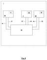
- Fig. 3 and 4 show the winder 1 during rotation of the turret 19 in a clockwise direction from the winding position to the change position.
- This rotation causes the Spulgut 3 with the holding and / or guiding device 20a, 20b interacts, namely, applies to the lateral surface of the guide rod 21a, 21b, wherein the circumferential angle of the system of Spulguts 3 to the lateral surface of the guide rod 21 a, 21 b increases with increasing rotation of the turret 19.
- the winding spindle 8b If, at the end of the rotation of the turret 19, the winding spindle 8b is in the winding position, while the winding spindle 8a with the bobbin 2 arranged thereon is in the change position, the winding material 3 must be brought into interaction with a catching device 23b, which in the embodiment shown in FIG Axial Scheme of the winding spindle 8 b or the bobbin tube 9 b is arranged, which is arranged on the side facing away from the turret 19 in front of the laying width and in front of the winding 10.
- the Spulgut traverse guide 12 is moved in an axial area outside the laying width.
- This movement of the Spulgut-traversing yarn guide 12 causes the angle of the Spulguts between the Spulgut-Changier proceedingss 12 and the receptacle 22b of the holding and / or guiding device 20b changed while the position and orientation of the Spulguts 3 between the receptacle 22b and the Spool 2 does not change. In this way it can be ensured that (in spite of the movement of the package traverse guide 12), the loose end 17 of the Spulguts 3 is not "pulled out” from the gap 16 between the rings 13, 14.
- the axial movement of the winding material traversing yarn guide 12 causes the winding material 3 to be deflected in the region of the radially oriented leg of the L. If the winding material 3 is then caught by the catching device 23b in the area of the empty winding spindle 8b, the winding cycle can begin on this winding spindle 8b.
- a severing of the Spulguts 3 is carried out by a separate separator. It is also possible that a cutting of the Spulguts 3 in the region of the holding and / or guiding device 20 takes place, for which purpose a separate separating device may be present. It is also possible that by means of an increase in the tension in the winding material 3 a severing in the region of the holding and / or guiding device 20, possibly at a corresponding cutting edge thereof, is brought about.
- FIG. 5 illustrated partial cross section has the intermediate space 16 in a first approximation U-shaped, radially outwardly open cross section, wherein the base leg of the U is formed by the lateral surface 11 of the winding 10, while the side legs of the U of the end faces 28, 27 of the rings 13, 14 are formed.
- the side legs of the U is stepped.
- this side leg is longer than the rectilinear side legs of U. formed by the face 27 of the ring 14.
- the end 17 of the Spulguts 3 is inserted, inserted or retracted. Since the distance 15 of the end face 27 of the ring 14 from the annular surface formed by the partial ring 24 of the axial end face 28 of the ring 13 is smaller than the width B 18 of the Spulguts 3, the Spulgut 3 is supported with its end faces on the end faces 27, 28th of the rings 13, 14 from.
- the end 17 of the Spulguts 3 is elastically clamped between the end faces 27, 28, which results in an axial contact force between the end 17 of the Spulguts 3 and the end faces 27, 28.
- the axial contact force leads to a frictional force between the end 17 of the Spulguts 3 and the end faces 27, 28. This frictional force forms a resistance to an outlet of the end 17 of the Spulguts 3 from the gap 16.
- the step 29 of the end face 28 is a positive obstacle against an exit of the end 17 of the Spulguts 3 from the gap 16.
- the end 17 of the Spulguts 3 for this embodiment a form-fitting and frictional engagement with the rings 13, 14 on the coil. 2 secured.
- Fig. 6 shows an alternative embodiment, in which not only the ring 13 is formed with partial rings 24, 25, but also the ring 14 is formed with partial rings 30, 31.
- the outer partial ring 31 is arranged with an offset V 32 in the direction of the other ring 13 with respect to the inner partial ring 30, so that now also the end face 27 has a peripheral step 33.
- the end 17 of the Spulguts 3 at both end faces 27, 28 by the axial contact frictionally and as a result of the steps 29, 33 positively secured against an exit from the gap 16.
- intermediate space 16 is in particular a bending elasticity of the cross section of the Spulguts 3 to a bending axis, which is oriented in the longitudinal direction of the Spulguts exploited.
- this can be utilized by generating a kind of folding or bending of the cross section of the material to be wound 3 about the said bending axis, whereby the insertion of the end 17 into the narrowed space 16 is made possible in the first place.
- the ring 14 has according to Fig. 5 and have the rings 13, 14 according to Fig. 6 an axial extent which is greater than the width B of the Spulguts 3, namely by the size of the offset V is greater than this.
- the illustrated embodiments are not intended to limit the invention. So it is quite possible that the rings 13, 14 and the partial rings 24, 25, 30, 31 have a greater width than shown, so that quite a winding of the rings 13, 14 can be carried out with a reciprocating motion of the traversing unit 7 , It is also possible that several turns of the end 17 of the Spulguts 3 are introduced into the gap 16.
- the formation of the rings 13, 14th may differ from the illustrated embodiments. Thus, more than two partial rings may be provided one above the other in a ring 13, 14. It is also possible that in the illustrated partial cross section, the intermediate space 16 has an arbitrary contour with arbitrarily shaped end faces 27, 28.
- the holding and / or guiding device 20 is designed such that it prevents axial displacement of the Spulguts 3 on the finished wound coil 2 exclusively in an axial direction in the direction of the catching device 23.
- the holding and / or guiding device 20 or provided on the holding and / or guide rod 21 holding device is designed as a holding hook.
- the winding machine 1 has a pressure roller for driving the coil and / or a contact roller over which the Spulgut 3 is applied to the lateral surface 11 of the winding 10, preferably before the winding of the rings 13, 14, the pressure roller or Application roller moves away from the lateral surface 11 of the winding 10 away.
- the insertion of the end 17 of the Spulguts 3 is brought into the gap 16 by rotation of the winding 10 about the axis of rotation or longitudinal axis of the winding spindle 8. But it is also possible that the insertion of the end 17 is at least partially caused by rotation of the turret 19 relative to the traversing unit 7.
- a traversing unit 7 any traversing units known per se can be used within the scope of the invention.
- a traversing unit can be used with a linear motor according to the aforementioned prior art, in which the preparation of the rings 13, 14, the partial rings 24, 25, 30, 31, the offset 26, 32 and the distance 15 by suitable electrical Actuation of the linear motor and thereby induced movement of the winding material traverse guide is generated.
- a traversing unit with a serrated shaft in particular according to the aforementioned prior art, in which the preparation of the rings 13, 14 and the partial rings 24, 25, 30, 31 in the region of the laying channel of the counterbore shaft with a deceleration of the Kehrgewindewelle to zero speed occurs and the offset 26, 32 and the distance 15 are made by turning the counter-threaded shaft.
- a drive in particular a piston-cylinder unit
- the entire traversing unit with Kehrgewindewelle or even only the Kehrgewindewelle is axially displaced.
- an embodiment is used in which the rings 13, 14 are each wound without offset.
- the end of the Spulguts in the region of its two edges on the two rings 13, 14 "clamped” and thus held by frictional engagement.
- an embodiment of the rings with an offset in the region of a ring or in each case an offset on both rings is used.
Landscapes
- Engineering & Computer Science (AREA)
- Textile Engineering (AREA)
- Winding Filamentary Materials (AREA)
- Winding Of Webs (AREA)
- Storage Of Web-Like Or Filamentary Materials (AREA)
Priority Applications (4)
| Application Number | Priority Date | Filing Date | Title |
|---|---|---|---|
| EP16183317.3A EP3281902B1 (fr) | 2016-08-09 | 2016-08-09 | Bobine, bobineuse, procede d'enroulement d'une bobine et produit logiciel |
| TW106125009A TWI701208B (zh) | 2016-08-09 | 2017-07-26 | 線軸、卷繞機、卷繞線軸的方法和軟體產品 |
| CN201710639869.4A CN107697728B (zh) | 2016-08-09 | 2017-07-31 | 线轴、卷绕机、卷绕线轴的方法和计算机可读的存储介质 |
| JP2017153920A JP2018039671A (ja) | 2016-08-09 | 2017-08-09 | スプール、巻き取り機械、スプールを巻き取るための方法およびソフトウェア製品 |
Applications Claiming Priority (1)
| Application Number | Priority Date | Filing Date | Title |
|---|---|---|---|
| EP16183317.3A EP3281902B1 (fr) | 2016-08-09 | 2016-08-09 | Bobine, bobineuse, procede d'enroulement d'une bobine et produit logiciel |
Publications (2)
| Publication Number | Publication Date |
|---|---|
| EP3281902A1 true EP3281902A1 (fr) | 2018-02-14 |
| EP3281902B1 EP3281902B1 (fr) | 2018-10-17 |
Family
ID=56681984
Family Applications (1)
| Application Number | Title | Priority Date | Filing Date |
|---|---|---|---|
| EP16183317.3A Active EP3281902B1 (fr) | 2016-08-09 | 2016-08-09 | Bobine, bobineuse, procede d'enroulement d'une bobine et produit logiciel |
Country Status (4)
| Country | Link |
|---|---|
| EP (1) | EP3281902B1 (fr) |
| JP (1) | JP2018039671A (fr) |
| CN (1) | CN107697728B (fr) |
| TW (1) | TWI701208B (fr) |
Cited By (4)
| Publication number | Priority date | Publication date | Assignee | Title |
|---|---|---|---|---|
| CN109335866A (zh) * | 2018-11-26 | 2019-02-15 | 无锡巨同创科技有限公司 | 一种收线机 |
| EP3597581A1 (fr) * | 2018-07-17 | 2020-01-22 | Starlinger & Co Gesellschaft m.b.H. | Dispositif d'enroulement d'une bande |
| CN111762634A (zh) * | 2020-06-03 | 2020-10-13 | 武汉理工大学 | 基于单层电缆卷筒的岸电电缆提升输送装置 |
| CN113371537A (zh) * | 2021-06-02 | 2021-09-10 | 山东玻纤集团股份有限公司 | 一种复合玻璃纤维卷绕机及其使用方法 |
Families Citing this family (1)
| Publication number | Priority date | Publication date | Assignee | Title |
|---|---|---|---|---|
| CN114014092B (zh) * | 2021-11-08 | 2023-04-07 | 巨石集团有限公司 | 一种玻璃纤维络纱机 |
Citations (13)
| Publication number | Priority date | Publication date | Assignee | Title |
|---|---|---|---|---|
| GB454555A (en) | 1935-03-01 | 1936-10-01 | Wrights Ropes Ltd | Improvements relating to balls or cops of twine, yarn and the like |
| DE2336755A1 (de) * | 1973-07-19 | 1975-02-06 | Weser Lenze Stahlkontor | Vorrichtung fuer den spulenwechsel beim spulen-lagenwickeln von kunststoffverpackungsband oder anderen schmalen baendern |
| DE2643421A1 (de) | 1975-09-25 | 1977-03-31 | Mitsubishi Heavy Ind Ltd | Verfahren und vorrichtung zum uebertragen eines garnfadens in einer automatischen spulmaschine |
| JPS62105871A (ja) * | 1985-10-31 | 1987-05-16 | Kanebo Ltd | 糸条端固定装置 |
| EP0453622A1 (fr) | 1990-04-23 | 1991-10-30 | Ssm Schärer Schweiter Mettler Ag | Procédé et dispositif pour enrouler un fil sur une bobine |
| WO2000024663A1 (fr) | 1998-10-28 | 2000-05-04 | Maschinenfabrik Rieter Ag | Va-et-vient de fil |
| WO2003033386A1 (fr) * | 2001-10-17 | 2003-04-24 | Barmag-Spinnzwirn Gmbh | Dispositif enrouleur |
| WO2003099695A1 (fr) | 2002-05-27 | 2003-12-04 | Georg Sahm Gmbh & Co. Kg | Procede et bobineuse pour l'enroulement d'un fil alimente en continu sur un tube pour former une bobine |
| EP1627840A1 (fr) | 2004-08-17 | 2006-02-22 | Schweninger Textil GmbH | Enroulement de fil |
| WO2009103095A1 (fr) | 2008-02-21 | 2009-08-27 | Lunatone Industrielle Elektronik Gmbh | Guide-fil sur roues |
| DE102008062161B3 (de) | 2008-12-13 | 2010-05-06 | Georg Sahm Gmbh & Co. Kg | Spulmaschine mit Trennvorrichtung |
| US20110309183A1 (en) * | 2009-12-22 | 2011-12-22 | Koichi Imai | Wire Bobbin Binding Device And Automatic Bobbin Winding Device Using Wire Bobbin Binding Device |
| DE102012018491A1 (de) | 2011-10-15 | 2013-04-18 | Oerlikon Textile Gmbh & Co. Kg | Aufspulmaschine und Verfahren zum Fixieren eines Fadenendes |
Family Cites Families (10)
| Publication number | Priority date | Publication date | Assignee | Title |
|---|---|---|---|---|
| GB585734A (en) * | 1944-09-19 | 1947-02-21 | British Belting & Asbestos Ltd | Improved means for anchoring yarn or thread to bobbins or the like |
| CH552530A (de) * | 1972-06-09 | 1974-08-15 | Schweizerische Viscose | Aufwickelvorrichtung. |
| US5393002A (en) * | 1990-07-21 | 1995-02-28 | Schubert & Salzer Maschinenfabrik Ag | Process and device for the constitution of a yarn end reserve winding on yarn packages of a textile machine |
| US5425509A (en) * | 1992-07-09 | 1995-06-20 | N.V. Bekaert S.A. | Spool filled with elongated metal element |
| CN1101006A (zh) * | 1992-11-26 | 1995-04-05 | 巴马格股份公司 | 绕纱方法及实施该方法的绕纱装置 |
| IT1265187B1 (it) * | 1993-11-16 | 1996-10-31 | Pirelli | Dispositivo di ancoraggio per fissare un capo terminale di una cordicella avvolta su una bobina di raccolta |
| JPH10212076A (ja) * | 1997-01-30 | 1998-08-11 | Hitoshi Takahashi | ホルダー付き糸巻 |
| US6007016A (en) * | 1998-04-03 | 1999-12-28 | Helton; Kennith H. | Multi-roll segment package for plastic tape and winding machine for same |
| CN203593476U (zh) * | 2013-12-06 | 2014-05-14 | 东莞市同亚电子科技有限公司 | 一种放线装置 |
| CN105584902A (zh) * | 2014-10-23 | 2016-05-18 | 无锡桥阳机械制造有限公司 | 一种带有可滑动压环的卷布筒 |
-
2016
- 2016-08-09 EP EP16183317.3A patent/EP3281902B1/fr active Active
-
2017
- 2017-07-26 TW TW106125009A patent/TWI701208B/zh active
- 2017-07-31 CN CN201710639869.4A patent/CN107697728B/zh active Active
- 2017-08-09 JP JP2017153920A patent/JP2018039671A/ja active Pending
Patent Citations (13)
| Publication number | Priority date | Publication date | Assignee | Title |
|---|---|---|---|---|
| GB454555A (en) | 1935-03-01 | 1936-10-01 | Wrights Ropes Ltd | Improvements relating to balls or cops of twine, yarn and the like |
| DE2336755A1 (de) * | 1973-07-19 | 1975-02-06 | Weser Lenze Stahlkontor | Vorrichtung fuer den spulenwechsel beim spulen-lagenwickeln von kunststoffverpackungsband oder anderen schmalen baendern |
| DE2643421A1 (de) | 1975-09-25 | 1977-03-31 | Mitsubishi Heavy Ind Ltd | Verfahren und vorrichtung zum uebertragen eines garnfadens in einer automatischen spulmaschine |
| JPS62105871A (ja) * | 1985-10-31 | 1987-05-16 | Kanebo Ltd | 糸条端固定装置 |
| EP0453622A1 (fr) | 1990-04-23 | 1991-10-30 | Ssm Schärer Schweiter Mettler Ag | Procédé et dispositif pour enrouler un fil sur une bobine |
| WO2000024663A1 (fr) | 1998-10-28 | 2000-05-04 | Maschinenfabrik Rieter Ag | Va-et-vient de fil |
| WO2003033386A1 (fr) * | 2001-10-17 | 2003-04-24 | Barmag-Spinnzwirn Gmbh | Dispositif enrouleur |
| WO2003099695A1 (fr) | 2002-05-27 | 2003-12-04 | Georg Sahm Gmbh & Co. Kg | Procede et bobineuse pour l'enroulement d'un fil alimente en continu sur un tube pour former une bobine |
| EP1627840A1 (fr) | 2004-08-17 | 2006-02-22 | Schweninger Textil GmbH | Enroulement de fil |
| WO2009103095A1 (fr) | 2008-02-21 | 2009-08-27 | Lunatone Industrielle Elektronik Gmbh | Guide-fil sur roues |
| DE102008062161B3 (de) | 2008-12-13 | 2010-05-06 | Georg Sahm Gmbh & Co. Kg | Spulmaschine mit Trennvorrichtung |
| US20110309183A1 (en) * | 2009-12-22 | 2011-12-22 | Koichi Imai | Wire Bobbin Binding Device And Automatic Bobbin Winding Device Using Wire Bobbin Binding Device |
| DE102012018491A1 (de) | 2011-10-15 | 2013-04-18 | Oerlikon Textile Gmbh & Co. Kg | Aufspulmaschine und Verfahren zum Fixieren eines Fadenendes |
Cited By (7)
| Publication number | Priority date | Publication date | Assignee | Title |
|---|---|---|---|---|
| EP3597581A1 (fr) * | 2018-07-17 | 2020-01-22 | Starlinger & Co Gesellschaft m.b.H. | Dispositif d'enroulement d'une bande |
| WO2020015989A1 (fr) * | 2018-07-17 | 2020-01-23 | Starlinger & Co Gesellschaft M.B.H. | Dispositif d'enroulement de bande |
| CN109335866A (zh) * | 2018-11-26 | 2019-02-15 | 无锡巨同创科技有限公司 | 一种收线机 |
| CN109335866B (zh) * | 2018-11-26 | 2023-08-22 | 无锡巨一同创科技有限公司 | 一种收线机 |
| CN111762634A (zh) * | 2020-06-03 | 2020-10-13 | 武汉理工大学 | 基于单层电缆卷筒的岸电电缆提升输送装置 |
| CN113371537A (zh) * | 2021-06-02 | 2021-09-10 | 山东玻纤集团股份有限公司 | 一种复合玻璃纤维卷绕机及其使用方法 |
| CN113371537B (zh) * | 2021-06-02 | 2023-07-11 | 山东玻纤集团股份有限公司 | 一种复合玻璃纤维卷绕机及其使用方法 |
Also Published As
| Publication number | Publication date |
|---|---|
| EP3281902B1 (fr) | 2018-10-17 |
| TW201808768A (zh) | 2018-03-16 |
| TWI701208B (zh) | 2020-08-11 |
| CN107697728B (zh) | 2021-01-01 |
| CN107697728A (zh) | 2018-02-16 |
| JP2018039671A (ja) | 2018-03-15 |
Similar Documents
| Publication | Publication Date | Title |
|---|---|---|
| EP3281902B1 (fr) | Bobine, bobineuse, procede d'enroulement d'une bobine et produit logiciel | |
| DE102012107015A1 (de) | Aufspulvorrichtung | |
| DD235282A5 (de) | Vorrichtung zum vorruebergehenden speichern und zufuehren eines durchlaufenden fadens zu einer textilmaschine | |
| DD144250A5 (de) | Vorrichtung zum verbinden von textilfaeden durch axialverdrillung | |
| WO2020094485A1 (fr) | Procédé et dispositif d'enroulement d'un fil multifilamentaire | |
| DE102011000590B3 (de) | Spulmaschine | |
| WO2013156302A1 (fr) | Bobineuse et procédé pour faire fonctionner une bobineuse | |
| EP2436632A1 (fr) | Dispositif de retenue pour un pistolet à aspiration de produit à enrouler | |
| EP1660400A1 (fr) | Procédè et dispositif de positionnement de plusieurs tubes dans une bobineuse | |
| WO2018069374A1 (fr) | Dispositif de bobinage | |
| DE2406550B2 (de) | Verfahren und Aufwickelvorrichtung zum Aufbringen von Reservewindungen auf eine Spulenhülse | |
| CH681802A5 (fr) | ||
| DE69305083T2 (de) | Fadenwickel mit trennbarer spule | |
| EP0615943A1 (fr) | Dispositif de bobinage double | |
| EP0349939B1 (fr) | Procédé pour le changement de bobines | |
| EP0093258A2 (fr) | Procédé pour éviter des rubans d'ordre entier ou fractionnaire en bobinage croisé au hasard d'un fil | |
| WO2008098873A1 (fr) | Dispositif de bobinage | |
| EP1479806A2 (fr) | Méthode pour obtenir une chaíne d'échantillonnage et ourdissoir d'échantillonnage | |
| DE4115339B4 (de) | Spulhülse | |
| EP2468669B1 (fr) | Procédé de fabrication d'une bobine de teinture | |
| DE3410758A1 (de) | Textilspindeleinheit | |
| DE19628402A1 (de) | Verfahren zur Vermeidung von Bildwicklungen | |
| DE3219880A1 (de) | Verfahren zur spiegelstoerung beim aufwickeln eines fadens in wilder wicklung | |
| DE1816671A1 (de) | Verfahren und Vorrichtung zur Herstellung von Spaltgarn | |
| DE2729303A1 (de) | Verfahren zum kontinuierlichen aufspulen von draht oder anderem fadenfoermigem gut und spulapparat hierfuer |
Legal Events
| Date | Code | Title | Description |
|---|---|---|---|
| PUAI | Public reference made under article 153(3) epc to a published international application that has entered the european phase |
Free format text: ORIGINAL CODE: 0009012 |
|
| STAA | Information on the status of an ep patent application or granted ep patent |
Free format text: STATUS: REQUEST FOR EXAMINATION WAS MADE |
|
| 17P | Request for examination filed |
Effective date: 20170818 |
|
| AK | Designated contracting states |
Kind code of ref document: A1 Designated state(s): AL AT BE BG CH CY CZ DE DK EE ES FI FR GB GR HR HU IE IS IT LI LT LU LV MC MK MT NL NO PL PT RO RS SE SI SK SM TR |
|
| AX | Request for extension of the european patent |
Extension state: BA ME |
|
| GRAP | Despatch of communication of intention to grant a patent |
Free format text: ORIGINAL CODE: EPIDOSNIGR1 |
|
| STAA | Information on the status of an ep patent application or granted ep patent |
Free format text: STATUS: GRANT OF PATENT IS INTENDED |
|
| INTG | Intention to grant announced |
Effective date: 20180403 |
|
| GRAS | Grant fee paid |
Free format text: ORIGINAL CODE: EPIDOSNIGR3 |
|
| GRAJ | Information related to disapproval of communication of intention to grant by the applicant or resumption of examination proceedings by the epo deleted |
Free format text: ORIGINAL CODE: EPIDOSDIGR1 |
|
| GRAL | Information related to payment of fee for publishing/printing deleted |
Free format text: ORIGINAL CODE: EPIDOSDIGR3 |
|
| STAA | Information on the status of an ep patent application or granted ep patent |
Free format text: STATUS: REQUEST FOR EXAMINATION WAS MADE |
|
| GRAR | Information related to intention to grant a patent recorded |
Free format text: ORIGINAL CODE: EPIDOSNIGR71 |
|
| STAA | Information on the status of an ep patent application or granted ep patent |
Free format text: STATUS: GRANT OF PATENT IS INTENDED |
|
| INTC | Intention to grant announced (deleted) | ||
| GRAA | (expected) grant |
Free format text: ORIGINAL CODE: 0009210 |
|
| STAA | Information on the status of an ep patent application or granted ep patent |
Free format text: STATUS: THE PATENT HAS BEEN GRANTED |
|
| INTG | Intention to grant announced |
Effective date: 20180829 |
|
| AK | Designated contracting states |
Kind code of ref document: B1 Designated state(s): AL AT BE BG CH CY CZ DE DK EE ES FI FR GB GR HR HU IE IS IT LI LT LU LV MC MK MT NL NO PL PT RO RS SE SI SK SM TR |
|
| REG | Reference to a national code |
Ref country code: GB Ref legal event code: FG4D Free format text: NOT ENGLISH |
|
| REG | Reference to a national code |
Ref country code: CH Ref legal event code: EP |
|
| REG | Reference to a national code |
Ref country code: IE Ref legal event code: FG4D Free format text: LANGUAGE OF EP DOCUMENT: GERMAN |
|
| REG | Reference to a national code |
Ref country code: DE Ref legal event code: R096 Ref document number: 502016002234 Country of ref document: DE Ref country code: AT Ref legal event code: REF Ref document number: 1053758 Country of ref document: AT Kind code of ref document: T Effective date: 20181115 |
|
| REG | Reference to a national code |
Ref country code: CH Ref legal event code: NV Representative=s name: RIEDERER HASLER AND PARTNER PATENTANWAELTE AG, CH |
|
| REG | Reference to a national code |
Ref country code: NL Ref legal event code: MP Effective date: 20181017 |
|
| REG | Reference to a national code |
Ref country code: LT Ref legal event code: MG4D |
|
| PG25 | Lapsed in a contracting state [announced via postgrant information from national office to epo] |
Ref country code: NL Free format text: LAPSE BECAUSE OF FAILURE TO SUBMIT A TRANSLATION OF THE DESCRIPTION OR TO PAY THE FEE WITHIN THE PRESCRIBED TIME-LIMIT Effective date: 20181017 |
|
| PG25 | Lapsed in a contracting state [announced via postgrant information from national office to epo] |
Ref country code: IS Free format text: LAPSE BECAUSE OF FAILURE TO SUBMIT A TRANSLATION OF THE DESCRIPTION OR TO PAY THE FEE WITHIN THE PRESCRIBED TIME-LIMIT Effective date: 20190217 Ref country code: ES Free format text: LAPSE BECAUSE OF FAILURE TO SUBMIT A TRANSLATION OF THE DESCRIPTION OR TO PAY THE FEE WITHIN THE PRESCRIBED TIME-LIMIT Effective date: 20181017 Ref country code: LT Free format text: LAPSE BECAUSE OF FAILURE TO SUBMIT A TRANSLATION OF THE DESCRIPTION OR TO PAY THE FEE WITHIN THE PRESCRIBED TIME-LIMIT Effective date: 20181017 Ref country code: PL Free format text: LAPSE BECAUSE OF FAILURE TO SUBMIT A TRANSLATION OF THE DESCRIPTION OR TO PAY THE FEE WITHIN THE PRESCRIBED TIME-LIMIT Effective date: 20181017 Ref country code: NO Free format text: LAPSE BECAUSE OF FAILURE TO SUBMIT A TRANSLATION OF THE DESCRIPTION OR TO PAY THE FEE WITHIN THE PRESCRIBED TIME-LIMIT Effective date: 20190117 Ref country code: HR Free format text: LAPSE BECAUSE OF FAILURE TO SUBMIT A TRANSLATION OF THE DESCRIPTION OR TO PAY THE FEE WITHIN THE PRESCRIBED TIME-LIMIT Effective date: 20181017 Ref country code: LV Free format text: LAPSE BECAUSE OF FAILURE TO SUBMIT A TRANSLATION OF THE DESCRIPTION OR TO PAY THE FEE WITHIN THE PRESCRIBED TIME-LIMIT Effective date: 20181017 Ref country code: FI Free format text: LAPSE BECAUSE OF FAILURE TO SUBMIT A TRANSLATION OF THE DESCRIPTION OR TO PAY THE FEE WITHIN THE PRESCRIBED TIME-LIMIT Effective date: 20181017 |
|
| PG25 | Lapsed in a contracting state [announced via postgrant information from national office to epo] |
Ref country code: AL Free format text: LAPSE BECAUSE OF FAILURE TO SUBMIT A TRANSLATION OF THE DESCRIPTION OR TO PAY THE FEE WITHIN THE PRESCRIBED TIME-LIMIT Effective date: 20181017 Ref country code: SE Free format text: LAPSE BECAUSE OF FAILURE TO SUBMIT A TRANSLATION OF THE DESCRIPTION OR TO PAY THE FEE WITHIN THE PRESCRIBED TIME-LIMIT Effective date: 20181017 Ref country code: RS Free format text: LAPSE BECAUSE OF FAILURE TO SUBMIT A TRANSLATION OF THE DESCRIPTION OR TO PAY THE FEE WITHIN THE PRESCRIBED TIME-LIMIT Effective date: 20181017 Ref country code: GR Free format text: LAPSE BECAUSE OF FAILURE TO SUBMIT A TRANSLATION OF THE DESCRIPTION OR TO PAY THE FEE WITHIN THE PRESCRIBED TIME-LIMIT Effective date: 20190118 Ref country code: PT Free format text: LAPSE BECAUSE OF FAILURE TO SUBMIT A TRANSLATION OF THE DESCRIPTION OR TO PAY THE FEE WITHIN THE PRESCRIBED TIME-LIMIT Effective date: 20190217 |
|
| REG | Reference to a national code |
Ref country code: DE Ref legal event code: R097 Ref document number: 502016002234 Country of ref document: DE |
|
| PG25 | Lapsed in a contracting state [announced via postgrant information from national office to epo] |
Ref country code: DK Free format text: LAPSE BECAUSE OF FAILURE TO SUBMIT A TRANSLATION OF THE DESCRIPTION OR TO PAY THE FEE WITHIN THE PRESCRIBED TIME-LIMIT Effective date: 20181017 |
|
| PLBE | No opposition filed within time limit |
Free format text: ORIGINAL CODE: 0009261 |
|
| STAA | Information on the status of an ep patent application or granted ep patent |
Free format text: STATUS: NO OPPOSITION FILED WITHIN TIME LIMIT |
|
| PG25 | Lapsed in a contracting state [announced via postgrant information from national office to epo] |
Ref country code: SM Free format text: LAPSE BECAUSE OF FAILURE TO SUBMIT A TRANSLATION OF THE DESCRIPTION OR TO PAY THE FEE WITHIN THE PRESCRIBED TIME-LIMIT Effective date: 20181017 Ref country code: EE Free format text: LAPSE BECAUSE OF FAILURE TO SUBMIT A TRANSLATION OF THE DESCRIPTION OR TO PAY THE FEE WITHIN THE PRESCRIBED TIME-LIMIT Effective date: 20181017 Ref country code: RO Free format text: LAPSE BECAUSE OF FAILURE TO SUBMIT A TRANSLATION OF THE DESCRIPTION OR TO PAY THE FEE WITHIN THE PRESCRIBED TIME-LIMIT Effective date: 20181017 Ref country code: SK Free format text: LAPSE BECAUSE OF FAILURE TO SUBMIT A TRANSLATION OF THE DESCRIPTION OR TO PAY THE FEE WITHIN THE PRESCRIBED TIME-LIMIT Effective date: 20181017 |
|
| 26N | No opposition filed |
Effective date: 20190718 |
|
| PG25 | Lapsed in a contracting state [announced via postgrant information from national office to epo] |
Ref country code: MC Free format text: LAPSE BECAUSE OF FAILURE TO SUBMIT A TRANSLATION OF THE DESCRIPTION OR TO PAY THE FEE WITHIN THE PRESCRIBED TIME-LIMIT Effective date: 20181017 Ref country code: LU Free format text: LAPSE BECAUSE OF NON-PAYMENT OF DUE FEES Effective date: 20190809 |
|
| REG | Reference to a national code |
Ref country code: BE Ref legal event code: MM Effective date: 20190831 |
|
| PG25 | Lapsed in a contracting state [announced via postgrant information from national office to epo] |
Ref country code: FR Free format text: LAPSE BECAUSE OF NON-PAYMENT OF DUE FEES Effective date: 20190831 Ref country code: IE Free format text: LAPSE BECAUSE OF NON-PAYMENT OF DUE FEES Effective date: 20190809 |
|
| PG25 | Lapsed in a contracting state [announced via postgrant information from national office to epo] |
Ref country code: BE Free format text: LAPSE BECAUSE OF NON-PAYMENT OF DUE FEES Effective date: 20190831 |
|
| GBPC | Gb: european patent ceased through non-payment of renewal fee |
Effective date: 20200809 |
|
| PG25 | Lapsed in a contracting state [announced via postgrant information from national office to epo] |
Ref country code: CY Free format text: LAPSE BECAUSE OF FAILURE TO SUBMIT A TRANSLATION OF THE DESCRIPTION OR TO PAY THE FEE WITHIN THE PRESCRIBED TIME-LIMIT Effective date: 20181017 |
|
| PG25 | Lapsed in a contracting state [announced via postgrant information from national office to epo] |
Ref country code: HU Free format text: LAPSE BECAUSE OF FAILURE TO SUBMIT A TRANSLATION OF THE DESCRIPTION OR TO PAY THE FEE WITHIN THE PRESCRIBED TIME-LIMIT; INVALID AB INITIO Effective date: 20160809 Ref country code: MT Free format text: LAPSE BECAUSE OF FAILURE TO SUBMIT A TRANSLATION OF THE DESCRIPTION OR TO PAY THE FEE WITHIN THE PRESCRIBED TIME-LIMIT Effective date: 20181017 |
|
| PG25 | Lapsed in a contracting state [announced via postgrant information from national office to epo] |
Ref country code: GB Free format text: LAPSE BECAUSE OF NON-PAYMENT OF DUE FEES Effective date: 20200809 |
|
| PG25 | Lapsed in a contracting state [announced via postgrant information from national office to epo] |
Ref country code: SI Free format text: LAPSE BECAUSE OF FAILURE TO SUBMIT A TRANSLATION OF THE DESCRIPTION OR TO PAY THE FEE WITHIN THE PRESCRIBED TIME-LIMIT Effective date: 20181017 |
|
| PG25 | Lapsed in a contracting state [announced via postgrant information from national office to epo] |
Ref country code: MK Free format text: LAPSE BECAUSE OF FAILURE TO SUBMIT A TRANSLATION OF THE DESCRIPTION OR TO PAY THE FEE WITHIN THE PRESCRIBED TIME-LIMIT Effective date: 20181017 |
|
| P01 | Opt-out of the competence of the unified patent court (upc) registered |
Effective date: 20230608 |
|
| PGFP | Annual fee paid to national office [announced via postgrant information from national office to epo] |
Ref country code: DE Payment date: 20250522 Year of fee payment: 10 |
|
| PGFP | Annual fee paid to national office [announced via postgrant information from national office to epo] |
Ref country code: TR Payment date: 20250805 Year of fee payment: 10 Ref country code: IT Payment date: 20250829 Year of fee payment: 10 |
|
| PGFP | Annual fee paid to national office [announced via postgrant information from national office to epo] |
Ref country code: BG Payment date: 20250821 Year of fee payment: 10 |
|
| PGFP | Annual fee paid to national office [announced via postgrant information from national office to epo] |
Ref country code: AT Payment date: 20250819 Year of fee payment: 10 |
|
| PGFP | Annual fee paid to national office [announced via postgrant information from national office to epo] |
Ref country code: CH Payment date: 20250901 Year of fee payment: 10 |
|
| PGFP | Annual fee paid to national office [announced via postgrant information from national office to epo] |
Ref country code: CZ Payment date: 20250729 Year of fee payment: 10 |