EP3282532A1 - Agencement de détection de défaut d'arc destiné à un bus électrique cc - Google Patents
Agencement de détection de défaut d'arc destiné à un bus électrique cc Download PDFInfo
- Publication number
- EP3282532A1 EP3282532A1 EP16183695.2A EP16183695A EP3282532A1 EP 3282532 A1 EP3282532 A1 EP 3282532A1 EP 16183695 A EP16183695 A EP 16183695A EP 3282532 A1 EP3282532 A1 EP 3282532A1
- Authority
- EP
- European Patent Office
- Prior art keywords
- arc fault
- conductors
- fault detection
- electric
- primary winding
- Prior art date
- Legal status (The legal status is an assumption and is not a legal conclusion. Google has not performed a legal analysis and makes no representation as to the accuracy of the status listed.)
- Granted
Links
Images



Classifications
-
- G—PHYSICS
- G01—MEASURING; TESTING
- G01R—MEASURING ELECTRIC VARIABLES; MEASURING MAGNETIC VARIABLES
- G01R31/00—Arrangements for testing electric properties; Arrangements for locating electric faults; Arrangements for electrical testing characterised by what is being tested not provided for elsewhere
- G01R31/12—Testing dielectric strength or breakdown voltage ; Testing or monitoring effectiveness or level of insulation, e.g. of a cable or of an apparatus, for example using partial discharge measurements; Electrostatic testing
- G01R31/1227—Testing dielectric strength or breakdown voltage ; Testing or monitoring effectiveness or level of insulation, e.g. of a cable or of an apparatus, for example using partial discharge measurements; Electrostatic testing of components, parts or materials
- G01R31/1263—Testing dielectric strength or breakdown voltage ; Testing or monitoring effectiveness or level of insulation, e.g. of a cable or of an apparatus, for example using partial discharge measurements; Electrostatic testing of components, parts or materials of solid or fluid materials, e.g. insulation films, bulk material; of semiconductors or LV electronic components or parts; of cable, line or wire insulation
- G01R31/1272—Testing dielectric strength or breakdown voltage ; Testing or monitoring effectiveness or level of insulation, e.g. of a cable or of an apparatus, for example using partial discharge measurements; Electrostatic testing of components, parts or materials of solid or fluid materials, e.g. insulation films, bulk material; of semiconductors or LV electronic components or parts; of cable, line or wire insulation of cable, line or wire insulation, e.g. using partial discharge measurements
-
- H—ELECTRICITY
- H02—GENERATION; CONVERSION OR DISTRIBUTION OF ELECTRIC POWER
- H02H—EMERGENCY PROTECTIVE CIRCUIT ARRANGEMENTS
- H02H1/00—Details of emergency protective circuit arrangements
- H02H1/0007—Details of emergency protective circuit arrangements concerning the detecting means
- H02H1/0015—Using arc detectors
-
- G—PHYSICS
- G01—MEASURING; TESTING
- G01R—MEASURING ELECTRIC VARIABLES; MEASURING MAGNETIC VARIABLES
- G01R31/00—Arrangements for testing electric properties; Arrangements for locating electric faults; Arrangements for electrical testing characterised by what is being tested not provided for elsewhere
- G01R31/12—Testing dielectric strength or breakdown voltage ; Testing or monitoring effectiveness or level of insulation, e.g. of a cable or of an apparatus, for example using partial discharge measurements; Electrostatic testing
-
- G—PHYSICS
- G01—MEASURING; TESTING
- G01R—MEASURING ELECTRIC VARIABLES; MEASURING MAGNETIC VARIABLES
- G01R31/00—Arrangements for testing electric properties; Arrangements for locating electric faults; Arrangements for electrical testing characterised by what is being tested not provided for elsewhere
- G01R31/12—Testing dielectric strength or breakdown voltage ; Testing or monitoring effectiveness or level of insulation, e.g. of a cable or of an apparatus, for example using partial discharge measurements; Electrostatic testing
- G01R31/14—Circuits therefor, e.g. for generating test voltages, sensing circuits
-
- G—PHYSICS
- G01—MEASURING; TESTING
- G01R—MEASURING ELECTRIC VARIABLES; MEASURING MAGNETIC VARIABLES
- G01R31/00—Arrangements for testing electric properties; Arrangements for locating electric faults; Arrangements for electrical testing characterised by what is being tested not provided for elsewhere
- G01R31/40—Testing power supplies
-
- H—ELECTRICITY
- H02—GENERATION; CONVERSION OR DISTRIBUTION OF ELECTRIC POWER
- H02H—EMERGENCY PROTECTIVE CIRCUIT ARRANGEMENTS
- H02H3/00—Emergency protective circuit arrangements for automatic disconnection directly responsive to an undesired change from normal electric working condition with or without subsequent reconnection ; integrated protection
- H02H3/26—Emergency protective circuit arrangements for automatic disconnection directly responsive to an undesired change from normal electric working condition with or without subsequent reconnection ; integrated protection responsive to difference between voltages or between currents; responsive to phase angle between voltages or between currents
- H02H3/32—Emergency protective circuit arrangements for automatic disconnection directly responsive to an undesired change from normal electric working condition with or without subsequent reconnection ; integrated protection responsive to difference between voltages or between currents; responsive to phase angle between voltages or between currents involving comparison of the voltage or current values at corresponding points in different conductors of a single system, e.g. of currents in go and return conductors
- H02H3/33—Emergency protective circuit arrangements for automatic disconnection directly responsive to an undesired change from normal electric working condition with or without subsequent reconnection ; integrated protection responsive to difference between voltages or between currents; responsive to phase angle between voltages or between currents involving comparison of the voltage or current values at corresponding points in different conductors of a single system, e.g. of currents in go and return conductors using summation current transformers
-
- H—ELECTRICITY
- H02—GENERATION; CONVERSION OR DISTRIBUTION OF ELECTRIC POWER
- H02S—GENERATION OF ELECTRIC POWER BY CONVERSION OF INFRARED RADIATION, VISIBLE LIGHT OR ULTRAVIOLET LIGHT, e.g. USING PHOTOVOLTAIC [PV] MODULES
- H02S50/00—Monitoring or testing of PV systems, e.g. load balancing or fault identification
-
- G—PHYSICS
- G01—MEASURING; TESTING
- G01R—MEASURING ELECTRIC VARIABLES; MEASURING MAGNETIC VARIABLES
- G01R19/00—Arrangements for measuring currents or voltages or for indicating presence or sign thereof
- G01R19/145—Indicating the presence of current or voltage
- G01R19/15—Indicating the presence of current
-
- H—ELECTRICITY
- H01—ELECTRIC ELEMENTS
- H01H—ELECTRIC SWITCHES; RELAYS; SELECTORS; EMERGENCY PROTECTIVE DEVICES
- H01H83/00—Protective switches, e.g. circuit-breaking switches, or protective relays operated by abnormal electrical conditions otherwise than solely by excess current
- H01H83/14—Protective switches, e.g. circuit-breaking switches, or protective relays operated by abnormal electrical conditions otherwise than solely by excess current operated by imbalance of two or more currents or voltages, e.g. for differential protection
- H01H83/144—Protective switches, e.g. circuit-breaking switches, or protective relays operated by abnormal electrical conditions otherwise than solely by excess current operated by imbalance of two or more currents or voltages, e.g. for differential protection with differential transformer
-
- Y—GENERAL TAGGING OF NEW TECHNOLOGICAL DEVELOPMENTS; GENERAL TAGGING OF CROSS-SECTIONAL TECHNOLOGIES SPANNING OVER SEVERAL SECTIONS OF THE IPC; TECHNICAL SUBJECTS COVERED BY FORMER USPC CROSS-REFERENCE ART COLLECTIONS [XRACs] AND DIGESTS
- Y02—TECHNOLOGIES OR APPLICATIONS FOR MITIGATION OR ADAPTATION AGAINST CLIMATE CHANGE
- Y02E—REDUCTION OF GREENHOUSE GAS [GHG] EMISSIONS, RELATED TO ENERGY GENERATION, TRANSMISSION OR DISTRIBUTION
- Y02E10/00—Energy generation through renewable energy sources
- Y02E10/50—Photovoltaic [PV] energy
- Y02E10/56—Power conversion systems, e.g. maximum power point trackers
Definitions
- the present invention relates to an arc fault detection arrangement for a DC electric bus.
- DC electric buses are widely adopted in many types of electric apparatuses, such as, for example, photovoltaic electric power generation systems.
- arc fault detection systems are typically provided to detect arc faults in DC electric buses.
- arc faults occurring in a photovoltaic electric power generation system may lead to fire events in the structure (e.g. the rooftop of a building) on which the photovoltaic panels are installed and may be quite dangerous for the safety of operators and resident people.
- the main aim of the present invention is to provide an arc fault detection arrangement for a DC electric bus, which enables the disadvantages described above to be overcome.
- another object of the present invention is to provide an arc fault detection arrangement, which has a particularly simple structure that can be easily installed on the field and easily integrated with other parts or components of the electric apparatus, to which it is dedicated.
- Yet another object of the present invention is to provide an arc fault detection arrangement, which is easy and inexpensive to produce at industrial level and requires a short time for installation on the field.
- the present invention related to a photovoltaic electric power generation apparatus, according to the following claim 14.
- the present invention related to a current sensing device, according to the following claim 15.
- the present invention relates to an arc fault detection arrangement 50 for a DC electric bus 100 of a low voltage electric apparatus 500.
- low voltage refers to operating voltages lower than 1 kV AC and 1.5 kV DC.
- the electric apparatus 500 may be of any type, according to the needs. As an example, it may be a low voltage switchgear or an electric power distribution grid.
- the arc fault detection arrangement 50 is however particularly suitable for installation in a photovoltaic electric power generation apparatus and will be described with particular reference to this application without intending to limit the scope of the invention.
- the source section 200 may be a section including one or more photovoltaic panels and adapted to provide DC electric power
- the load section 300 may be a section including an inverter adapted to receive DC electric power and provide AC electric power.
- each electric line L 1 , ..., L N of the electric bus 100 comprises at least a first conductor C1, which forms the supply conductor of the respective electric line.
- the first conductor C1s of each electric line L 1 , ..., L N has a first source portion C1 S , which is electrically connected with the source section 200 and has a first source terminal ST 1 , and a first load portion C1 L , which is electrically connected with the load section 300 and has a first load terminal LT 1 .
- the source portion C1 S and the load portion C1 L of each conductor C1 of each electric line L 1 , ..., L N are in electrical connection to ensure the electrical continuity between the source and load sections 200, 300 of the electric apparatus 500.
- the electric lines L 1 , ..., L N may not be provided with a return conductor as the return currents pass through the ground.
- the electric lines L 1 , ..., L N comprise also a return conductor.
- each electric line L 1 , ..., L N has a first conductor C1 (e.g. forming the supply conductor of the respective electric line) and a second conductor C2 (e.g. forming the return conductor of the respective electric line).
- first conductor C1 e.g. forming the supply conductor of the respective electric line
- second conductor C2 e.g. forming the return conductor of the respective electric line
- the first conductor C1 of each electric line L 1 , ..., L N has a first source portion C1 S , which is electrically connected with the source section 200 and has a first source terminal ST 1 , and a first load portion C1 L , which is electrically connected with the load section 300 and has a first load terminal LT 1 .
- the second conductor C2 of each electric line L 1 , ..., L N has a second source portion C2s, which is electrically connected with the source section 200 and has a second source terminal ST 2 , and a second load portion C2 L , which is electrically connected with the load section 300 and has a second load terminal LT 2 .
- the source portions C1 S , C2s and the load portions C1 L , C2 L of each conductor C1, C2 of each electric line L 1 , ..., L N are electrically connected in such a way to ensure the electrical continuity between the source and load sections 200 of the apparatus 500.
- the apparatus 500 may comprise suitable switching devices (not shown) operatively associated with the conductors of the electric lines L 1 , ..., L N to selectively interrupt these latter.
- DC currents flow along the conductors of the electric lines L 1 , ..., L N .
- AC noise currents may flow along the conductors of the electric lines L 1 , ..., L N (overlapped with said load currents).
- Such noise currents which generally have a well-defined spectral content, are normally generated by electric or electronic components included in the source and load sections 200, 300 of the electric apparatus 500.
- the electrical currents (DC or AC) flowing along the conductors of the electric lines L 1 , ..., L N may be of common-mode type or differential-mode type.
- the arc fault detection arrangement 50 of the invention is directed to detect the AC currents flowing along the conductors of the electric lines L 1 , ..., L N and determine whether said currents include arc currents indicative of the occurrence of an arc fault.
- the arc fault detection arrangement 50 comprises an arc fault detector 10 adapted to receive and process detection signals DS indicative of the AC currents (e.g. the noise currents and possibly the arc currents overlapped to the DC load currents) flowing along the electric lines L 1 , ..., L N in order to detect the occurrence of an arc fault in said electric lines.
- the AC currents e.g. the noise currents and possibly the arc currents overlapped to the DC load currents
- the arc fault detector 10 is adapted to process the detection signals DS, which are indicative of the AC currents flowing along the electric lines L 1 , ..., L N , and determine the presence of possible arc currents (which are thus indicative of incoming or occurring arc faults) by selectively identifying these latter on the first of their spectral content.
- the arc fault detector 10 provides control signals CS indicative of the presence of an arc fault in the electric lines L 1 , ..., L N of the electric bus 100.
- the control signals CS may be sent to other control devices and/or directly to the switching devices adapted to interrupt the electric lines L 1 , ..., L N .
- the arc fault detector 10 may be a device of known type and will not be described in further detail for the sake of brevity.
- the arc fault detection arrangement 50 comprises a current sensing device 1 adapted to detect the AC currents flowing along the electric lines L 1 , ..., L N and provide the detection signals DS to the arc fault detection 10.
- the current sensing device 1 is configured as an amperometric transformer (configured as magnetic coil or as a Rogowski coil) having a single magnetic circuit that is enchained with the electric lines L 1 , ..., L N .
- the magnetic circuit 2 may be formed by one or more shaped pieces of magnetic material (magnetic core).
- Such pieces of magnetic material may be arranged to form one or more airgaps along the magnetic circuit 2 or may be formed by a magnetic material having a relatively low magnetic permeability.
- the magnetic circuit 2 may be formed by one or more shaped pieces of non-magnetic material (Rogowski coil with non-magnetic core).
- Such pieces of non-magnetic material may be arranged to form one or more airgaps along the magnetic circuit 2.
- the magnetic circuit 2 may be a magnetic flux path fully realized in air (Rogowski coil in air).
- the magnetic circuit 2 has a relative magnetic permeability lower than or equal to 150.
- the magnetic circuit 2 is formed by a core having a toroidal structure.
- the sensing device 1 comprises primary winding means 21 operatively associated with the magnetic circuit 2.
- the primary winding means 21 comprise at least a plurality of first primary winding conductors PW1 1 , ..., PW1 N , which are enchained with the magnetic circuit 2.
- Each first primary winding conductor PW1 1 , ..., PW1 N is adapted to be electrically connected in series with a source portion C1 S and a load portions C1 L of a respective first line conductors C1 of a corresponding electric line L 1 , ..., L N .
- each first primary winding conductor PW1 1 , ..., PW1 N has positive and negative (in terms of voltage applied thereto) terminals T 1 , T 2 electrically connected with the terminals ST 1 , LT 1 of the source and load portions C1 S , C1 L of a respective first line conductor C1 of a corresponding electric line L 1 , ..., L N .
- the AC currents flowing along the first line conductors C1 of the electric lines L 1 , ..., L N circulate along the first primary winding conductors PW1 1 , ..., PW1 N and generate a magnetic flux that circulates along the magnetic circuit 2.
- the first primary winding conductors PW1 1 , ..., PW1 N are formed by corresponding rigid conductive elements arranged on a support.
- the first primary winding conductors PW1 1 , ..., PW1 N are formed by corresponding conductive tracks arranged on a support.
- the sensing device 1 comprises secondary winding means 22 magnetically coupleable with the primary winding means 21 through the magnetic circuit 2.
- the secondary winding means 22 comprise at least a first secondary winding conductor SW1.
- a secondary current flows along the first secondary winding conductor SW1.
- Such a secondary current is indicative of the AC currents that have generated such a magnetic flux.
- the first secondary winding conductor SW1 is electrically connected (at its terminals S1, S2) with the arc fault detector 10.
- the mentioned secondary currents flowing along the first secondary winding conductor SW1 represents the detection signals DS provided to the arc fault detector 10.
- the secondary winding means 22 may comprise an interface circuit 23 electrically connected between the terminals S1, S2 of the first secondary winding conductor SW1 and the arc fault detector 10 ( figure 1 ).
- the interface circuit 23 may be configured to receive the secondary currents circulating along the first secondary winding conductor SW1 and provide the detection signals DS to the arc fault detector 10.
- a detection signals DS may be a voltage signal.
- the secondary winding means 22 comprise at least a second secondary winding conductor SW2 ( figures 2 , 4 ).
- the second secondary winding conductor SW2 is electrically connected (at its terminals S2, S3) with the arc fault detector 10 to receive a test current from this latter.
- the second secondary winding conductor SW2 has a terminal (S2) in common with the first secondary winding conductor SW1.
- the first secondary winding conductor SW1, and possibly the second secondary winding conductor SW2 are formed by corresponding rigid conductive elements arranged on a support.
- the primary winding means 21 of the current sensing device 1 comprise a plurality of second primary winding conductors PW2 1 , ..., PW2 N , which are enchained with the magnetic circuit 2 ( figures 3 , 4 ).
- Each second primary winding conductor PW2 1 , ..., PW2 N is adapted to be electrically connected in series with a source portion C2s and a load portions C2 L of a respective second line conductor C2 of a corresponding electric line L 1 , ..., L N .
- each second primary winding conductor PW2 1 , ..., PW2 N has positive and negative terminals T 3 , T 4 (in terms of voltage applied thereto) electrically connected with the terminals ST 2 , LT 2 of the source and load portions C2s, C2 L of a respective second line conductor C2 of a corresponding electric line L 1 , ..., L N .
- the AC currents flowing along the second line conductors C2 of the electric lines L 1 , ..., L N circulate along the second primary winding conductors PW2 1 , ..., PW2 N and generate a magnetic flux that circulates along the magnetic circuit 2.
- the second primary winding conductors PW2 1 , ..., PW2 N are formed by corresponding rigid conductive elements arranged on a support.
- the second primary winding conductors PW2 1 , ..., PW2 N are formed by corresponding conductive tracks arranged on a support.
- the first and second primary winding conductors PW1 1 , ..., PW1 N , PW2 1 , ..., PW2 N are adapted to be electrically connected in series with the source portions C1 S , C2 S and the load portions C1 L , C2 L of the corresponding first and second line conductors C1, C2 of the electric lines L1, ..., LN in such a way that common-mode electric currents flowing along the first and second primary winding conductors PW1 1 , ..., PW1 N , PW2 1 , ..., PW2 N generate magnetic fluxes having opposite directions.
- the first and second primary winding conductors PW1 1 , ..., PW1 N , PW2 1 , ..., PW2 N are electrically connected to the source portions C1 S , C2 S and the load portions C1 L , C2 L of the corresponding first and second line conductors C1, C2 with mutually opposite polarities.
- the solution adopted by the above described embodiment of the invention allows cancelling or remarkably reducing the disturbances, which are induced by the common mode AC currents flowing along the conductors of the electric lines L 1 , ..., L N , on the detection signals DS.
- the magnetic fluxes generated by these currents are mutually compensated thanks to the physical layout (e.g. according to the connection arrangements described above) provided for the primary winding conductors PW1 1 , ..., PW1 N , PW2 1 , ..., PW2 N in relation to the respective conductors of said electric lines.
- the detection signals DS provided by current sensing device 1 thus result as indicative of the sole differential mode AC currents flowing along the conductors of the electric lines L 1 , ..., L N , which represent the useful physical quantities to be sensed for arc fault detection purposes.
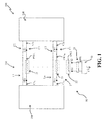
- FIG 1 a possible embodiment of the arc fault detection arrangement 50 is shown.
- each electric line L 1 , ..., L N has a first conductor C1 (forming the supply conductor of the respective electric line) and a second conductor C2 (forming the return conductor of the respective electric line).
- the arc fault detection arrangement 50 comprises a current sensing device 1 having a single magnetic circuit 2.
- the current sensing device 1 has primary winding means 21 including a plurality of first primary conductors PW1 1 , ..., PW1 N electrically connected in series with the source and load portions C1 S , C1 L of the first conductors C1 and secondary winding means 22 including the sole first secondary winding conductor SW1.
- the single magnetic circuit 2 is enchained only with the first conductors C1 of the electric line L 1 , ..., L N .
- the secondary winding means 22 comprises an interface circuit 23 electrically connected with the terminals S1, S2 of the first secondary winding conductor SW1 and with the arc fault detector 10.
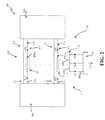
- each electric line L 1 , ..., L N has a first conductor C1 (forming the supply conductor of the respective electric line) and a second conductor C2 (forming the return conductor of the respective electric line).
- the arc fault detection arrangement 50 comprises a current sensing device 1 having a single magnetic circuit 2.
- the current sensing device 1 has primary winding means 21 including a plurality of first primary conductors PW1 1 , ..., PW1 N electrically connected in series with the source and load portions C1 S , C1 L of the first conductors C1.
- the single magnetic circuit 2 is enchained only with the first conductors C1 of the electric line L 1 , ..., L N .
- the current sensing device 1 has secondary winding means 22 including the first secondary winding conductor SW1 and the second secondary winding conductor SW2, which have a terminal S2 in common.
- the terminals S1, S2, S3 of the secondary winding conductors SW1, SW2 are electrically connected with an arc fault detector 10.
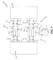
- the arc fault detection arrangement 50 comprises a current sensing device 1 having a single magnetic circuit 2.
- the current sensing device 1 has primary winding means 21 including a plurality of first primary conductors PW1 1 , ..., PW1 N electrically connected in series with the source and load portions C1 S , C1 L of the first conductors C1 and a plurality of second primary conductors PW2 1 , ..., PW2 N electrically connected in series with the source and load portions C2s, C2 L of the second conductors C2.
- the single magnetic circuit 2 is enchained with both the first and second conductors C1, C2 of the electric line L 1 , ..., L N .
- the first and second primary winding conductors PW1 1 , ..., PW1 N , PW2 1 , ..., PW2 N are electrically connected to the source portions C1 S , C2 S and the load portions C1 L , C2 L of the corresponding first and second line conductors C1, C2 with opposite polarities.
- the current sensing device 1 has secondary winding means 22 including the sole first secondary winding conductor SW1, which is electrically connected (at its terminals S1, S2) with an arc fault detector 10.
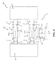
- the arc fault detection arrangement 50 comprises a current sensing device 1 having a single magnetic circuit 2.
- the current sensing device 1 has primary winding means 21 including a plurality of first primary conductors PW1 1 , ..., PW1 N electrically connected in series with the source and load portions C1 S , C1 L of the first conductors C1 and a plurality of second primary conductors PW2 1 , ..., PW2 N electrically connected in series with the source and load portions C2s, C2 L of the second conductors C2.
- the single magnetic circuit 2 is enchained with both the first and second conductors C1, C2 of the electric line L 1 , ..., L N .
- the first and second primary winding conductors PW1 1 , ..., PW1 N , PW2 1 , ..., PW2 N are electrically connected to the source portions C1 S , C2 S and the load portions C1 L , C2 L of the corresponding first and second line conductors C1, C2 with opposite polarities.
- the current sensing device 1 has secondary winding means 22 including the first secondary winding conductor SW1 and the second secondary winding conductor SW2, which have a terminal S2 in common.
- the terminals S1, S2, S3 of the secondary winding conductors SW1, SW2 are electrically connected with an arc fault detector 10.
- This embodiment is a variant of the one shown in figure 2 , which has been designed for an electric bus 100 having only two electric lines L 1 , L 2 , each having a first conductor C1 (forming the supply conductor of the respective electric line) and a second conductor C2 (forming the return conductor of the respective electric line).
- the arc fault detection arrangement 50 comprises a current sensing device 1 having a single magnetic circuit 2.
- the current sensing device 1 has primary winding means 21 including two first primary conductors PW1 1 , PW1 2 electrically connected in series with the source and load portions C1 S , C1 L of the first conductors C1 and secondary winding means 22 including the first secondary winding conductor SW1 and the second secondary winding conductor SW2, which have a terminal S2 in common.
- the terminals S1, S2, S3 of the secondary winding conductors SW1, SW2 are electrically connected with an arc fault detector 10.
- This embodiment is a variant of the one shown in figure 4 , which has been designed for an electric bus 100 having only two electric lines L 1 , L 2 , each having a first conductor C1 (forming the supply conductor of the respective electric line) and a second conductor C2 (forming the return conductor of the respective electric line).
- the arc fault detection arrangement 50 comprises a current sensing device 1 having a single magnetic circuit 2.
- the current sensing device 1 has primary winding means 21 including the first primary conductors PW1 1 , PW1 2 electrically connected in series with the source and load portions of the first conductors C1 of the electric lines L 1 , L 2 and the second primary conductors PW2 1 , PW2 2 electrically connected in series with the source and load portions of the second conductors C2 of the electric lines L 1 , L 2 .
- the first and second primary winding conductors PW1 1 , PW1 2 , PW2 1 , PW2 2 are electrically connected to the source and load portions of the corresponding first and second line conductors C1, C2 with opposite polarities.
- the current sensing device 1 has secondary winding means 22 including the first secondary winding conductor SW1 and the second secondary winding conductor SW2, which have a terminal S2 in common.
- the terminals S1, S2, S3 of the secondary winding conductors SW1, SW2 are electrically connected with an arc fault detector 10.
- the current sensing device 1 may have primary winding means 21 including only first primary winding conductors PW1 1 , ..., PW1 N operatively associated with the return conductors (in the above embodiments of figures 1-2 represented by the conductors C2) of the electric lines L 1 , ..., L N .
- the currents sensing device 1 may be advantageously arranged so as to be mountable on a support 60, which may be, for example, a PCB.
- This solution greatly facilitates the structural integration of the current sensing device 1 with components or parts of the electric apparatus 50 without a substantial increase of the occupied volumes.
- the current sensing device 1 may be mounted on the main board 60 of an inverter included in the load section 300.
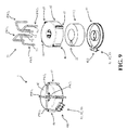
- the current sensing device 1 comprises an outer enclosure 4 mechanically fixable to a support 60 (e.g. a PCB) and adapted to define a volume, in which a core, which forms the magnetic circuit 2, and the secondary winding means 22 of the current sensing device are accommodated.
- a support 60 e.g. a PCB
- the outer enclosure 4 comprises a first portion 41 and a second portion 42 mechanically coupleable one to another (e.g. by means of a snap-fit or a press-fit connection).
- the outer enclosure 4 may be fixed to the support in such a way that the symmetry axis passing through the toroidal core 2 is perpendicular to a mounting surface 60A of the support 60 (horizontal mounting of the core 2).
- the toroidal core 2 is oriented along a plane parallel to the support 60.
- the outer enclosure 4 may be fixed to the support in such a way that the symmetry axis passing through the toroidal core 2 is parallel to a mounting surface 60A of the support 60 (vertical mounting of the core 2).
- the toroidal core 2 is oriented along a plane perpendicular to the support 60.
- the current sensing device 1 comprises first conductive bridges PW1 1 , PW1 2 forming the first primary winding conductors of the current sensing device 1.
- the first rigid conductive bridges PW1 1 , PW1 2 are arranged externally to the outer enclosure 4 and are coupleable with the support 60, preferably at their ends T1, T2.
- the first conductive bridges PW1 1 , PW1 2 are shaped so as to be at least partially wound around the core 2 when they are operatively coupled (i.e. mechanically fixed and electrically connected) with the support 60.
- the first conductive bridges PW1 1 , PW1 2 are arranged so as to form a conductive path that is at least partially enchained with the core, so that possible AC currents flowing along the PW1 1 , PW1 2 generate a magnetic flux that circulates along the core 2.
- the first conductive bridges PW1 1 , PW1 2 are substantially U-shaped and have first and second leg portions respectively passing through and out of the core 2 and directed towards the support 60, in such a way that their ends T1, T2 can be coupled with the support 60.
- the first conductive bridges PW1 1 , PW1 2 are structurally rigid.
- the enclosure 4 in particular the second portion 41 thereof, comprises first retaining means 46 adapted to be removably coupled with the first conductive bridges PW1 1 , PW1 2 .
- the first retaining means 46 comprise first deformable protrusions of the enclosure 4, in particular of the second portion 41 thereof, which are shaped so as to fit with the first conductive bridges PW1 1 , PW1 2 , in particular with leg portions thereof, and couple with said bridges by means of mechanical coupling of the snap-fit or press-fit type.
- the current sensing device 1 may comprise also second conductive bridges PW2 1 , PW2 2 forming the second primary winding conductors of the current sensing device 1.
- the second conductive bridges PW2 1 , PW2 2 are arranged externally to the outer enclosure 4 and are coupleable with the support 60, preferably at their ends T3, T4.
- the second conductive bridges PW2 1 , PW2 2 are shaped so as to be partially wound around the core 2 when they are operatively coupled (i.e. mechanically fixed and electrically connected) with the support 60.
- the second conductive bridges PW2 1 , PW2 2 are substantially U-shaped and have first and second leg portions respectively passing through and out of the core 2 and directed towards the support 60, in such a way that their ends T3, T4 can be coupled with the support 60.
- the second conductive bridges PW2 1 , PW2 2 are structurally rigid.
- the enclosure 4 in particular the second portion 41 thereof, comprises second retaining means 47 adapted to be removably coupled with the second conductive bridges PW2 1 , PW2 2 .
- the second retaining means 47 comprise second deformable protrusions of the enclosure 4, in particular of the second portion 41 thereof, which are shaped so as to fit with the second conductive bridges PW2 1 , PW2 2 , in particular with leg portions thereof, and couple with said bridges by means of mechanical coupling of the snap-fit or press-fit type.
- the current sensing device 1 is designed for an arc fault detection arrangement configured according to the embodiment shown in figure 5 .
- the current sensing device 1 comprises an outer enclosure 4 accommodating a toroidal core forming the magnetic circuit 2 and the secondary winding means 22 of the current sensing device.
- the outer enclosure 4 comprises the first portion 41 mechanically fixed to the support 60 and the second portion 42 mechanically coupled with the first portion 41 (horizontal mounting of the core 2).
- the first portion 41 comprises the output sub-portion 410 accommodating the terminals S1, S2, S3 of the secondary winding conductors SW1, SW2 of the secondary winding means 22.
- the current sensing device 1 comprises the first rigid conductive bridges PW1 1 , PW1 2 forming the first primary winding conductors of the current sensing device 1.
- the first rigid conductive bridges PW1 1 , PW1 2 are arranged externally to the outer enclosure 4 in parallel one to another.
- the first conductive bridges PW1 1 , PW1 2 are U-shaped and have their leg portions respectively passing through and out of the core 2 and directed towards the support 60, in such a way to be coupled with the support 60 at the ends T1, T2.
- the second portion 41 of the enclosure 4 thereof comprises first deformable protrusions 46 removably coupled with the leg portions of the first conductive bridges PW1 1 , PW1 2 .
- the current sensing device 1 is designed for an arc fault detection arrangement configured according to the embodiment shown in figure 8 .
- the current sensing device 1 comprises an outer enclosure 4 accommodating a toroidal core forming the magnetic circuit 2 and the secondary winding means 22 of the current sensing device.
- the outer enclosure 4 comprises the first portion 41 mechanically fixed to the support 60 and the second portion 42 mechanically coupled with the first portion 41 (horizontal mounting of the core 2).
- the first portion 41 comprises the output sub-portion 410 accommodating the terminals S1, S2, S3 of the secondary winding conductors SW1, SW2 of the secondary winding means 22.
- the current sensing device 1 comprises the first rigid conductive bridges PW1 1 , PW1 2 forming the first primary winding conductors of the current sensing device 1.
- the first rigid conductive bridges PW1 1 , PW1 2 are arranged externally to the outer enclosure 4.
- the first conductive bridges PW1 1 , PW1 2 are U-shaped and have their leg portions respectively passing through and out of the core 2 and directed towards the support 60, in such a way to be coupled with the support 60 at the ends T1, T2.
- the second portion 41 of the enclosure 4 comprises first deformable protrusions 46 removably coupled with leg portions of the first conductive bridges PW1 1 , PW1 2 .
- the current sensing device 1 comprises also the second rigid conductive bridges PW2 1 , PW2 2 forming the second primary winding conductors of the current sensing device 1.
- the second rigid conductive bridges PW2 1 , PW2 2 are arranged externally to the outer enclosure 4, in parallel one to another and with the first rigid conductive bridges PW1 1 , PW1 2 .
- the second conductive bridges PW2 1 , PW2 2 are U-shaped and have their leg portions respectively passing through and out of the core 2 and directed towards the support 60, in such a way to be coupled with the support 60 at the ends T3, T4.
- the second portion 41 of the enclosure 4 comprises second deformable protrusions 47 removably coupled with the leg portions of the second conductive bridges PW2 1 , PW2 2 .
- the secondary winding means 22 may include one or more corresponding further rigid conductive bridges arranged externally to the outer enclosure 4.
- the outer enclosure 4 is adapted to define a volume in air.
- the secondary winding means 22 of the current sensing device may accommodated in such a volume. In this case, they may be formed by turns wounded in air.
- the secondary winding means 22 may include one or more corresponding further rigid conductive bridges arranged externally to the outer enclosure 4.
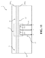
- the current sensing device 1 comprises primary winding conductors formed by conductive tracks deposited on a support 60 (e.g. a PCB).
- the current sensing device 1 comprises first primary conductive tracks forming the first primary winding conductors of the current sensing device 1.
- the current sensing device 1 may also comprise second primary conductive tracks forming the second primary winding conductors of the current sensing device 1.
- the first and second primary conductive tracks are advantageously deposited on the support 60 with deposition techniques of known type.
- the current sensing device 1 comprises first secondary winding conductors and, possibly, second secondary winding conductors, which are arranged so as to be magnetically coupleable with the primary conductive tracks forming the primary winding conductors of the current sensing device.
- the current sensing device 1 may comprise an outer enclosure (not shown) mounted on the support 60 and defining a volume for accommodating at least partially the first and the secondary winding means 21, 22 of the current sensing device.
- the current sensing device 1 is designed for an arc fault detection arrangement configured according to the embodiment shown in figure 5 .
- the current sensing device 1 adopts a single magnetic circuit 2 formed by a magnetic flux path fully realized in air (Rogowski coil in air).
- the current sensing device 1 comprises the first primary conductive tracks PW1 1 , PW1 2 forming the first primary winding conductors of the current sensing device 1.
- the current sensing device 1 comprises first and second secondary winding conductors SW1, SW2, which are formed by multiple turns wounded in air.
- the first and second secondary winding conductors SW1, SW2 are positioned adjacent to the first primary conductive tracks PW1 1 , PW1 2 so as to be magnetically coupleable with these latter, through the magnetic circuit 2.
- the current sensing device 1 may comprise additional conductive tracks 220 deposited on the support 60 to electrically connect the first and second secondary winding conductors SW1, SW2 with the respective terminals S1, S2, S3.
- the mentioned conductive tracks PW1 1 , PW1 2 , 220 may be deposited on the support 60 with deposition techniques of known type.
- the arc fault detection arrangement allows achieving the intended aims and objects.
- the arc fault detection arrangement has a particularly simple structure.
- the arc fault detection arrangement comprises a current sensing device having a sturdy and compact structure, which can be manufactured at industrial level with highly automated operations and which is easily mountable on a PCB support.
- the PCB-mountable construction of the current sensing device allows avoiding cabling operations and allows remarkably reducing installation errors.
- the arc fault detection arrangement adopts a single arc fault detector for all the electric lines of the DC electric bus.
- the arc fault detection arrangement thus provides relevant advantages in terms of size and cost reduction with respect to known solutions of the state of the art.
- the arc fault detection arrangement allows obtaining high attenuation levels of common mode disturbances. This allows obtaining high levels of reliability in arc fault detection and consequent high levels of immunity to false tripping.
- the arc fault detection arrangement can be easily installed on the field and that can be easily integrated with other parts or components of the electric apparatus, to which it is dedicated. This allows obtaining a further reduction of manufacturing and installation costs with respect to known solutions of the state of the art.
Landscapes
- Physics & Mathematics (AREA)
- General Physics & Mathematics (AREA)
- Engineering & Computer Science (AREA)
- Power Engineering (AREA)
- Measuring Instrument Details And Bridges, And Automatic Balancing Devices (AREA)
- Testing Of Short-Circuits, Discontinuities, Leakage, Or Incorrect Line Connections (AREA)
- Emergency Protection Circuit Devices (AREA)
- Measurement Of Current Or Voltage (AREA)
- Photovoltaic Devices (AREA)
Priority Applications (5)
| Application Number | Priority Date | Filing Date | Title |
|---|---|---|---|
| EP16183695.2A EP3282532B1 (fr) | 2016-08-11 | 2016-08-11 | Agencement de détection de défaut d'arc destiné à un bus électrique cc |
| ES16183695T ES2882034T3 (es) | 2016-08-11 | 2016-08-11 | Disposición de detección de fallas de arco para un bus eléctrico de CC |
| JP2017150174A JP2018072320A (ja) | 2016-08-11 | 2017-08-02 | Dc電気母線のためのアーク故障検出構成 |
| US15/675,389 US10673224B2 (en) | 2016-08-11 | 2017-08-11 | Arc fault detection arrangement for a DC electric bus |
| CN201710682923.3A CN107728012B (zh) | 2016-08-11 | 2017-08-11 | 用于直流电气母线的电弧故障检测装备 |
Applications Claiming Priority (1)
| Application Number | Priority Date | Filing Date | Title |
|---|---|---|---|
| EP16183695.2A EP3282532B1 (fr) | 2016-08-11 | 2016-08-11 | Agencement de détection de défaut d'arc destiné à un bus électrique cc |
Publications (2)
| Publication Number | Publication Date |
|---|---|
| EP3282532A1 true EP3282532A1 (fr) | 2018-02-14 |
| EP3282532B1 EP3282532B1 (fr) | 2021-06-02 |
Family
ID=56618098
Family Applications (1)
| Application Number | Title | Priority Date | Filing Date |
|---|---|---|---|
| EP16183695.2A Active EP3282532B1 (fr) | 2016-08-11 | 2016-08-11 | Agencement de détection de défaut d'arc destiné à un bus électrique cc |
Country Status (5)
| Country | Link |
|---|---|
| US (1) | US10673224B2 (fr) |
| EP (1) | EP3282532B1 (fr) |
| JP (1) | JP2018072320A (fr) |
| CN (1) | CN107728012B (fr) |
| ES (1) | ES2882034T3 (fr) |
Cited By (3)
| Publication number | Priority date | Publication date | Assignee | Title |
|---|---|---|---|---|
| CN109239558A (zh) * | 2018-11-08 | 2019-01-18 | 重庆大学 | 一种直流故障电弧检测及保护装置 |
| CN110221136A (zh) * | 2018-03-01 | 2019-09-10 | 通用电气航空系统有限公司 | 用于检测电弧故障的系统和方法 |
| EP3647797A1 (fr) * | 2018-11-05 | 2020-05-06 | ABB Schweiz AG | Onduleur comprennant des moyens pour la détection d'arc dans une installation photovoltaïque |
Families Citing this family (9)
| Publication number | Priority date | Publication date | Assignee | Title |
|---|---|---|---|---|
| DK201470457A1 (en) * | 2014-07-18 | 2016-02-01 | Emazys Technologies Aps | Method and System of Fault Detection and Localisation in DC-Systems |
| ES2880955T3 (es) * | 2016-08-11 | 2021-11-26 | Fimer S P A | Una disposición de detección de fallas de arco para bus eléctrico de CC |
| CN108919074A (zh) * | 2018-07-27 | 2018-11-30 | 安徽吉乃尔电器科技有限公司 | 一种光伏逆变器的电弧故障检测装置 |
| JP7170221B2 (ja) * | 2018-11-09 | 2022-11-14 | パナソニックIpマネジメント株式会社 | アーク検出回路、ブレーカ、パワーコンディショナ、太陽光パネル、太陽光パネル付属モジュール、接続箱、アーク検出方法及びプログラム |
| CN110504918B (zh) * | 2019-09-17 | 2021-07-23 | 丰郅(上海)新能源科技有限公司 | 电弧检测装置以及电弧检测方法 |
| US11067638B2 (en) * | 2019-12-12 | 2021-07-20 | Sma Solar Technology Ag | Method of and system for detecting a serial arc fault in a power circuit |
| US12088080B2 (en) | 2020-03-11 | 2024-09-10 | Panasonic Intellectual Property Management Co., Ltd. | Arc detection device, solar inverter, indoor wiring system, breaker, solar panel, solar panel-attached module, and junction box |
| EP4454081A4 (fr) * | 2021-12-22 | 2025-12-24 | Powell Electrical Systems Inc | Habilitation d'un équipement à tolérer et maîtriser les effets de défauts d'arc internes |
| WO2024031960A1 (fr) * | 2022-08-11 | 2024-02-15 | 台达电子工业股份有限公司 | Onduleur solaire |
Citations (6)
| Publication number | Priority date | Publication date | Assignee | Title |
|---|---|---|---|---|
| DE2425080A1 (de) * | 1974-05-24 | 1975-12-11 | Bbc Brown Boveri & Cie | Einrichtung zum messen und weiterverarbeiten eines differenzstromes |
| WO2000074192A1 (fr) * | 1998-05-28 | 2000-12-07 | X-L Synergy, Llc | Disjoncteur a surete integree |
| EP2393178A2 (fr) * | 2010-06-07 | 2011-12-07 | Eaton Corporation | Protection, surveillance ou appareil d'indication pour un appareil de génération électrique de courant continu ou plusieurs chaînes |
| US20130038971A1 (en) * | 2010-06-03 | 2013-02-14 | Shakira Limited | Arc fault detector for ac or dc installations |
| WO2013049501A2 (fr) * | 2011-09-30 | 2013-04-04 | Solarbos, Inc. | Système permettant de combiner la puissance en courant continu de plusieurs entrées |
| WO2016001824A1 (fr) * | 2014-06-30 | 2016-01-07 | Societa' Elettrica S.R.L. | Dispositif de protection d'une centrale photovoltaïque à courant continu |
Family Cites Families (4)
| Publication number | Priority date | Publication date | Assignee | Title |
|---|---|---|---|---|
| US5459630A (en) * | 1993-09-15 | 1995-10-17 | Eaton Corporation | Self testing circuit breaker ground fault and sputtering arc trip unit |
| US8599523B1 (en) * | 2011-07-29 | 2013-12-03 | Leviton Manufacturing Company, Inc. | Arc fault circuit interrupter |
| US8958182B2 (en) * | 2012-08-27 | 2015-02-17 | Eaton Corporation | Method and apparatus for enhancing arc fault signal for detection in photovoltaic system |
| CN103592550B (zh) * | 2013-11-26 | 2018-11-23 | 华侨大学 | 一种电弧故障检测方法及保护装置 |
-
2016
- 2016-08-11 ES ES16183695T patent/ES2882034T3/es active Active
- 2016-08-11 EP EP16183695.2A patent/EP3282532B1/fr active Active
-
2017
- 2017-08-02 JP JP2017150174A patent/JP2018072320A/ja active Pending
- 2017-08-11 CN CN201710682923.3A patent/CN107728012B/zh active Active
- 2017-08-11 US US15/675,389 patent/US10673224B2/en active Active
Patent Citations (6)
| Publication number | Priority date | Publication date | Assignee | Title |
|---|---|---|---|---|
| DE2425080A1 (de) * | 1974-05-24 | 1975-12-11 | Bbc Brown Boveri & Cie | Einrichtung zum messen und weiterverarbeiten eines differenzstromes |
| WO2000074192A1 (fr) * | 1998-05-28 | 2000-12-07 | X-L Synergy, Llc | Disjoncteur a surete integree |
| US20130038971A1 (en) * | 2010-06-03 | 2013-02-14 | Shakira Limited | Arc fault detector for ac or dc installations |
| EP2393178A2 (fr) * | 2010-06-07 | 2011-12-07 | Eaton Corporation | Protection, surveillance ou appareil d'indication pour un appareil de génération électrique de courant continu ou plusieurs chaînes |
| WO2013049501A2 (fr) * | 2011-09-30 | 2013-04-04 | Solarbos, Inc. | Système permettant de combiner la puissance en courant continu de plusieurs entrées |
| WO2016001824A1 (fr) * | 2014-06-30 | 2016-01-07 | Societa' Elettrica S.R.L. | Dispositif de protection d'une centrale photovoltaïque à courant continu |
Cited By (4)
| Publication number | Priority date | Publication date | Assignee | Title |
|---|---|---|---|---|
| CN110221136A (zh) * | 2018-03-01 | 2019-09-10 | 通用电气航空系统有限公司 | 用于检测电弧故障的系统和方法 |
| EP3647797A1 (fr) * | 2018-11-05 | 2020-05-06 | ABB Schweiz AG | Onduleur comprennant des moyens pour la détection d'arc dans une installation photovoltaïque |
| CN109239558A (zh) * | 2018-11-08 | 2019-01-18 | 重庆大学 | 一种直流故障电弧检测及保护装置 |
| CN109239558B (zh) * | 2018-11-08 | 2020-10-02 | 重庆大学 | 一种直流故障电弧检测及保护装置 |
Also Published As
| Publication number | Publication date |
|---|---|
| EP3282532B1 (fr) | 2021-06-02 |
| JP2018072320A (ja) | 2018-05-10 |
| CN107728012B (zh) | 2021-08-13 |
| US20180048138A1 (en) | 2018-02-15 |
| CN107728012A (zh) | 2018-02-23 |
| ES2882034T3 (es) | 2021-12-01 |
| US10673224B2 (en) | 2020-06-02 |
Similar Documents
| Publication | Publication Date | Title |
|---|---|---|
| EP3282532B1 (fr) | Agencement de détection de défaut d'arc destiné à un bus électrique cc | |
| US10673223B2 (en) | Arc fault detection arrangement for a DC electric bus | |
| US4356443A (en) | Detection of arcing faults in polyphase electric machines | |
| CN103384446B (zh) | 用于电弧故障检测的装置和方法 | |
| CN111771250B (zh) | 电流互感器 | |
| AU2022224778B2 (en) | A multi-channel inverter for a photovoltaic apparatus | |
| US20200144963A1 (en) | Inverter for a photovoltaic plant | |
| CN210039896U (zh) | 防铁芯多点接地的电压互感器 | |
| KR20020041973A (ko) | 누전 차단기 | |
| JP7108919B2 (ja) | 電路監視システム及び配電システム | |
| KR101184996B1 (ko) | 변류기와 조합된 영상변류기 | |
| JP2019174303A (ja) | 電路監視システム、信号入力装置、信号抽出装置及び配電システム | |
| KR20100034828A (ko) | 지락 보호시스템 | |
| JP2017207311A (ja) | 電力計測システム | |
| JP2024089272A (ja) | 絶縁監視装置 | |
| JPH0493669A (ja) | 漏電検出装置 | |
| Taskinen et al. | Monitor Ground Fault Leakage Current | |
| KR101314122B1 (ko) | 대기전력 차단방식의 영상고조파 저감장치 및 영상고조파 저감장치 작동상태 판단 방법 | |
| JP2012204567A (ja) | トランス用ボビン及びトランス | |
| JP2007139506A (ja) | 活線絶縁診断装置 | |
| JPH03215760A (ja) | 地絡検出装置 | |
| JPH09113544A (ja) | 変電所等の電流計測システム | |
| CZ278392A3 (en) | Indicator of fault current passage |
Legal Events
| Date | Code | Title | Description |
|---|---|---|---|
| PUAI | Public reference made under article 153(3) epc to a published international application that has entered the european phase |
Free format text: ORIGINAL CODE: 0009012 |
|
| STAA | Information on the status of an ep patent application or granted ep patent |
Free format text: STATUS: THE APPLICATION HAS BEEN PUBLISHED |
|
| AK | Designated contracting states |
Kind code of ref document: A1 Designated state(s): AL AT BE BG CH CY CZ DE DK EE ES FI FR GB GR HR HU IE IS IT LI LT LU LV MC MK MT NL NO PL PT RO RS SE SI SK SM TR |
|
| AX | Request for extension of the european patent |
Extension state: BA ME |
|
| STAA | Information on the status of an ep patent application or granted ep patent |
Free format text: STATUS: REQUEST FOR EXAMINATION WAS MADE |
|
| 17P | Request for examination filed |
Effective date: 20180723 |
|
| RBV | Designated contracting states (corrected) |
Designated state(s): AL AT BE BG CH CY CZ DE DK EE ES FI FR GB GR HR HU IE IS IT LI LT LU LV MC MK MT NL NO PL PT RO RS SE SI SK SM TR |
|
| REG | Reference to a national code |
Ref country code: DE Ref legal event code: R079 Ref document number: 602016058729 Country of ref document: DE Free format text: PREVIOUS MAIN CLASS: H02H0001000000 Ipc: G01R0019150000 |
|
| RAP1 | Party data changed (applicant data changed or rights of an application transferred) |
Owner name: MARICI HOLDINGS THE NETHERLANDS B.V. |
|
| RIC1 | Information provided on ipc code assigned before grant |
Ipc: H02S 50/00 20140101ALI20201116BHEP Ipc: H01H 83/14 20060101ALI20201116BHEP Ipc: G01R 31/40 20200101ALI20201116BHEP Ipc: G01R 19/15 20060101AFI20201116BHEP Ipc: H02H 3/33 20060101ALI20201116BHEP Ipc: G01R 31/12 20200101ALI20201116BHEP Ipc: H02H 1/00 20060101ALI20201116BHEP |
|
| GRAP | Despatch of communication of intention to grant a patent |
Free format text: ORIGINAL CODE: EPIDOSNIGR1 |
|
| STAA | Information on the status of an ep patent application or granted ep patent |
Free format text: STATUS: GRANT OF PATENT IS INTENDED |
|
| INTG | Intention to grant announced |
Effective date: 20210113 |
|
| GRAS | Grant fee paid |
Free format text: ORIGINAL CODE: EPIDOSNIGR3 |
|
| GRAA | (expected) grant |
Free format text: ORIGINAL CODE: 0009210 |
|
| STAA | Information on the status of an ep patent application or granted ep patent |
Free format text: STATUS: THE PATENT HAS BEEN GRANTED |
|
| REG | Reference to a national code |
Ref country code: CH Ref legal event code: EP |
|
| AK | Designated contracting states |
Kind code of ref document: B1 Designated state(s): AL AT BE BG CH CY CZ DE DK EE ES FI FR GB GR HR HU IE IS IT LI LT LU LV MC MK MT NL NO PL PT RO RS SE SI SK SM TR |
|
| REG | Reference to a national code |
Ref country code: GB Ref legal event code: FG4D |
|
| REG | Reference to a national code |
Ref country code: AT Ref legal event code: REF Ref document number: 1398957 Country of ref document: AT Kind code of ref document: T Effective date: 20210615 |
|
| REG | Reference to a national code |
Ref country code: IE Ref legal event code: FG4D |
|
| REG | Reference to a national code |
Ref country code: DE Ref legal event code: R096 Ref document number: 602016058729 Country of ref document: DE |
|
| RAP2 | Party data changed (patent owner data changed or rights of a patent transferred) |
Owner name: FIMER S.P.A. |
|
| REG | Reference to a national code |
Ref country code: LT Ref legal event code: MG9D |
|
| PG25 | Lapsed in a contracting state [announced via postgrant information from national office to epo] |
Ref country code: FI Free format text: LAPSE BECAUSE OF FAILURE TO SUBMIT A TRANSLATION OF THE DESCRIPTION OR TO PAY THE FEE WITHIN THE PRESCRIBED TIME-LIMIT Effective date: 20210602 Ref country code: LT Free format text: LAPSE BECAUSE OF FAILURE TO SUBMIT A TRANSLATION OF THE DESCRIPTION OR TO PAY THE FEE WITHIN THE PRESCRIBED TIME-LIMIT Effective date: 20210602 Ref country code: HR Free format text: LAPSE BECAUSE OF FAILURE TO SUBMIT A TRANSLATION OF THE DESCRIPTION OR TO PAY THE FEE WITHIN THE PRESCRIBED TIME-LIMIT Effective date: 20210602 Ref country code: BG Free format text: LAPSE BECAUSE OF FAILURE TO SUBMIT A TRANSLATION OF THE DESCRIPTION OR TO PAY THE FEE WITHIN THE PRESCRIBED TIME-LIMIT Effective date: 20210902 |
|
| REG | Reference to a national code |
Ref country code: NL Ref legal event code: MP Effective date: 20210602 |
|
| REG | Reference to a national code |
Ref country code: AT Ref legal event code: MK05 Ref document number: 1398957 Country of ref document: AT Kind code of ref document: T Effective date: 20210602 |
|
| PG25 | Lapsed in a contracting state [announced via postgrant information from national office to epo] |
Ref country code: GR Free format text: LAPSE BECAUSE OF FAILURE TO SUBMIT A TRANSLATION OF THE DESCRIPTION OR TO PAY THE FEE WITHIN THE PRESCRIBED TIME-LIMIT Effective date: 20210903 Ref country code: LV Free format text: LAPSE BECAUSE OF FAILURE TO SUBMIT A TRANSLATION OF THE DESCRIPTION OR TO PAY THE FEE WITHIN THE PRESCRIBED TIME-LIMIT Effective date: 20210602 Ref country code: PL Free format text: LAPSE BECAUSE OF FAILURE TO SUBMIT A TRANSLATION OF THE DESCRIPTION OR TO PAY THE FEE WITHIN THE PRESCRIBED TIME-LIMIT Effective date: 20210602 Ref country code: NO Free format text: LAPSE BECAUSE OF FAILURE TO SUBMIT A TRANSLATION OF THE DESCRIPTION OR TO PAY THE FEE WITHIN THE PRESCRIBED TIME-LIMIT Effective date: 20210902 Ref country code: SE Free format text: LAPSE BECAUSE OF FAILURE TO SUBMIT A TRANSLATION OF THE DESCRIPTION OR TO PAY THE FEE WITHIN THE PRESCRIBED TIME-LIMIT Effective date: 20210602 Ref country code: RS Free format text: LAPSE BECAUSE OF FAILURE TO SUBMIT A TRANSLATION OF THE DESCRIPTION OR TO PAY THE FEE WITHIN THE PRESCRIBED TIME-LIMIT Effective date: 20210602 |
|
| REG | Reference to a national code |
Ref country code: ES Ref legal event code: FG2A Ref document number: 2882034 Country of ref document: ES Kind code of ref document: T3 Effective date: 20211201 |
|
| PG25 | Lapsed in a contracting state [announced via postgrant information from national office to epo] |
Ref country code: EE Free format text: LAPSE BECAUSE OF FAILURE TO SUBMIT A TRANSLATION OF THE DESCRIPTION OR TO PAY THE FEE WITHIN THE PRESCRIBED TIME-LIMIT Effective date: 20210602 Ref country code: CZ Free format text: LAPSE BECAUSE OF FAILURE TO SUBMIT A TRANSLATION OF THE DESCRIPTION OR TO PAY THE FEE WITHIN THE PRESCRIBED TIME-LIMIT Effective date: 20210602 Ref country code: SM Free format text: LAPSE BECAUSE OF FAILURE TO SUBMIT A TRANSLATION OF THE DESCRIPTION OR TO PAY THE FEE WITHIN THE PRESCRIBED TIME-LIMIT Effective date: 20210602 Ref country code: SK Free format text: LAPSE BECAUSE OF FAILURE TO SUBMIT A TRANSLATION OF THE DESCRIPTION OR TO PAY THE FEE WITHIN THE PRESCRIBED TIME-LIMIT Effective date: 20210602 Ref country code: AT Free format text: LAPSE BECAUSE OF FAILURE TO SUBMIT A TRANSLATION OF THE DESCRIPTION OR TO PAY THE FEE WITHIN THE PRESCRIBED TIME-LIMIT Effective date: 20210602 Ref country code: NL Free format text: LAPSE BECAUSE OF FAILURE TO SUBMIT A TRANSLATION OF THE DESCRIPTION OR TO PAY THE FEE WITHIN THE PRESCRIBED TIME-LIMIT Effective date: 20210602 Ref country code: PT Free format text: LAPSE BECAUSE OF FAILURE TO SUBMIT A TRANSLATION OF THE DESCRIPTION OR TO PAY THE FEE WITHIN THE PRESCRIBED TIME-LIMIT Effective date: 20211004 Ref country code: RO Free format text: LAPSE BECAUSE OF FAILURE TO SUBMIT A TRANSLATION OF THE DESCRIPTION OR TO PAY THE FEE WITHIN THE PRESCRIBED TIME-LIMIT Effective date: 20210602 |
|
| REG | Reference to a national code |
Ref country code: DE Ref legal event code: R097 Ref document number: 602016058729 Country of ref document: DE |
|
| REG | Reference to a national code |
Ref country code: CH Ref legal event code: PL |
|
| PG25 | Lapsed in a contracting state [announced via postgrant information from national office to epo] |
Ref country code: MC Free format text: LAPSE BECAUSE OF FAILURE TO SUBMIT A TRANSLATION OF THE DESCRIPTION OR TO PAY THE FEE WITHIN THE PRESCRIBED TIME-LIMIT Effective date: 20210602 |
|
| PLBE | No opposition filed within time limit |
Free format text: ORIGINAL CODE: 0009261 |
|
| STAA | Information on the status of an ep patent application or granted ep patent |
Free format text: STATUS: NO OPPOSITION FILED WITHIN TIME LIMIT |
|
| REG | Reference to a national code |
Ref country code: BE Ref legal event code: MM Effective date: 20210831 |
|
| PG25 | Lapsed in a contracting state [announced via postgrant information from national office to epo] |
Ref country code: LI Free format text: LAPSE BECAUSE OF NON-PAYMENT OF DUE FEES Effective date: 20210831 Ref country code: DK Free format text: LAPSE BECAUSE OF FAILURE TO SUBMIT A TRANSLATION OF THE DESCRIPTION OR TO PAY THE FEE WITHIN THE PRESCRIBED TIME-LIMIT Effective date: 20210602 Ref country code: CH Free format text: LAPSE BECAUSE OF NON-PAYMENT OF DUE FEES Effective date: 20210831 |
|
| 26N | No opposition filed |
Effective date: 20220303 |
|
| PG25 | Lapsed in a contracting state [announced via postgrant information from national office to epo] |
Ref country code: LU Free format text: LAPSE BECAUSE OF NON-PAYMENT OF DUE FEES Effective date: 20210811 Ref country code: AL Free format text: LAPSE BECAUSE OF FAILURE TO SUBMIT A TRANSLATION OF THE DESCRIPTION OR TO PAY THE FEE WITHIN THE PRESCRIBED TIME-LIMIT Effective date: 20210602 |
|
| PG25 | Lapsed in a contracting state [announced via postgrant information from national office to epo] |
Ref country code: IE Free format text: LAPSE BECAUSE OF NON-PAYMENT OF DUE FEES Effective date: 20210811 Ref country code: FR Free format text: LAPSE BECAUSE OF NON-PAYMENT OF DUE FEES Effective date: 20210831 Ref country code: BE Free format text: LAPSE BECAUSE OF NON-PAYMENT OF DUE FEES Effective date: 20210831 |
|
| PG25 | Lapsed in a contracting state [announced via postgrant information from national office to epo] |
Ref country code: HU Free format text: LAPSE BECAUSE OF FAILURE TO SUBMIT A TRANSLATION OF THE DESCRIPTION OR TO PAY THE FEE WITHIN THE PRESCRIBED TIME-LIMIT; INVALID AB INITIO Effective date: 20160811 |
|
| PG25 | Lapsed in a contracting state [announced via postgrant information from national office to epo] |
Ref country code: CY Free format text: LAPSE BECAUSE OF FAILURE TO SUBMIT A TRANSLATION OF THE DESCRIPTION OR TO PAY THE FEE WITHIN THE PRESCRIBED TIME-LIMIT Effective date: 20210602 |
|
| P01 | Opt-out of the competence of the unified patent court (upc) registered |
Effective date: 20230530 |
|
| PG25 | Lapsed in a contracting state [announced via postgrant information from national office to epo] |
Ref country code: MK Free format text: LAPSE BECAUSE OF FAILURE TO SUBMIT A TRANSLATION OF THE DESCRIPTION OR TO PAY THE FEE WITHIN THE PRESCRIBED TIME-LIMIT Effective date: 20210602 |
|
| PG25 | Lapsed in a contracting state [announced via postgrant information from national office to epo] |
Ref country code: MT Free format text: LAPSE BECAUSE OF FAILURE TO SUBMIT A TRANSLATION OF THE DESCRIPTION OR TO PAY THE FEE WITHIN THE PRESCRIBED TIME-LIMIT Effective date: 20210602 |
|
| PGFP | Annual fee paid to national office [announced via postgrant information from national office to epo] |
Ref country code: ES Payment date: 20250926 Year of fee payment: 10 |
|
| PGFP | Annual fee paid to national office [announced via postgrant information from national office to epo] |
Ref country code: DE Payment date: 20250820 Year of fee payment: 10 |
|
| PGFP | Annual fee paid to national office [announced via postgrant information from national office to epo] |
Ref country code: IT Payment date: 20250825 Year of fee payment: 10 |
|
| PGFP | Annual fee paid to national office [announced via postgrant information from national office to epo] |
Ref country code: GB Payment date: 20250821 Year of fee payment: 10 |
|
| PG25 | Lapsed in a contracting state [announced via postgrant information from national office to epo] |
Ref country code: TR Free format text: LAPSE BECAUSE OF FAILURE TO SUBMIT A TRANSLATION OF THE DESCRIPTION OR TO PAY THE FEE WITHIN THE PRESCRIBED TIME-LIMIT Effective date: 20210602 |