EP3283162B1 - Medizinisches ventil, kit mit solch einem ventil und verfahren zur herstellung eines gemisches oder einer emulsion - Google Patents
Medizinisches ventil, kit mit solch einem ventil und verfahren zur herstellung eines gemisches oder einer emulsion Download PDFInfo
- Publication number
- EP3283162B1 EP3283162B1 EP16717351.7A EP16717351A EP3283162B1 EP 3283162 B1 EP3283162 B1 EP 3283162B1 EP 16717351 A EP16717351 A EP 16717351A EP 3283162 B1 EP3283162 B1 EP 3283162B1
- Authority
- EP
- European Patent Office
- Prior art keywords
- mixing
- syringe
- connector
- syringes
- medical
- Prior art date
- Legal status (The legal status is an assumption and is not a legal conclusion. Google has not performed a legal analysis and makes no representation as to the accuracy of the status listed.)
- Active
Links
Images


Classifications
-
- A—HUMAN NECESSITIES
- A61—MEDICAL OR VETERINARY SCIENCE; HYGIENE
- A61M—DEVICES FOR INTRODUCING MEDIA INTO, OR ONTO, THE BODY; DEVICES FOR TRANSDUCING BODY MEDIA OR FOR TAKING MEDIA FROM THE BODY; DEVICES FOR PRODUCING OR ENDING SLEEP OR STUPOR
- A61M39/00—Tubes, tube connectors, tube couplings, valves, access sites or the like, specially adapted for medical use
- A61M39/22—Valves or arrangement of valves
- A61M39/223—Multiway valves
-
- A—HUMAN NECESSITIES
- A61—MEDICAL OR VETERINARY SCIENCE; HYGIENE
- A61M—DEVICES FOR INTRODUCING MEDIA INTO, OR ONTO, THE BODY; DEVICES FOR TRANSDUCING BODY MEDIA OR FOR TAKING MEDIA FROM THE BODY; DEVICES FOR PRODUCING OR ENDING SLEEP OR STUPOR
- A61M39/00—Tubes, tube connectors, tube couplings, valves, access sites or the like, specially adapted for medical use
- A61M39/10—Tube connectors; Tube couplings
- A61M39/105—Multi-channel connectors or couplings, e.g. for connecting multi-lumen tubes
-
- A—HUMAN NECESSITIES
- A61—MEDICAL OR VETERINARY SCIENCE; HYGIENE
- A61M—DEVICES FOR INTRODUCING MEDIA INTO, OR ONTO, THE BODY; DEVICES FOR TRANSDUCING BODY MEDIA OR FOR TAKING MEDIA FROM THE BODY; DEVICES FOR PRODUCING OR ENDING SLEEP OR STUPOR
- A61M5/00—Devices for bringing media into the body in a subcutaneous, intra-vascular or intramuscular way; Accessories therefor, e.g. filling or cleaning devices, arm-rests
- A61M5/007—Devices for bringing media into the body in a subcutaneous, intra-vascular or intramuscular way; Accessories therefor, e.g. filling or cleaning devices, arm-rests for contrast media
-
- A—HUMAN NECESSITIES
- A61—MEDICAL OR VETERINARY SCIENCE; HYGIENE
- A61J—CONTAINERS SPECIALLY ADAPTED FOR MEDICAL OR PHARMACEUTICAL PURPOSES; DEVICES OR METHODS SPECIALLY ADAPTED FOR BRINGING PHARMACEUTICAL PRODUCTS INTO PARTICULAR PHYSICAL OR ADMINISTERING FORMS; DEVICES FOR ADMINISTERING FOOD OR MEDICINES ORALLY; BABY COMFORTERS; DEVICES FOR RECEIVING SPITTLE
- A61J1/00—Containers specially adapted for medical or pharmaceutical purposes
- A61J1/14—Details; Accessories therefor
- A61J1/20—Arrangements for transferring or mixing fluids, e.g. from vial to syringe
- A61J1/2003—Accessories used in combination with means for transfer or mixing of fluids, e.g. for activating fluid flow, separating fluids, filtering fluid or venting
- A61J1/2048—Connecting means
- A61J1/2058—Connecting means having multiple connecting ports
-
- A—HUMAN NECESSITIES
- A61—MEDICAL OR VETERINARY SCIENCE; HYGIENE
- A61M—DEVICES FOR INTRODUCING MEDIA INTO, OR ONTO, THE BODY; DEVICES FOR TRANSDUCING BODY MEDIA OR FOR TAKING MEDIA FROM THE BODY; DEVICES FOR PRODUCING OR ENDING SLEEP OR STUPOR
- A61M25/00—Catheters; Hollow probes
- A61M25/0021—Catheters; Hollow probes characterised by the form of the tubing
- A61M2025/0042—Microcatheters, cannula or the like having outside diameters around 1 mm or less
-
- A—HUMAN NECESSITIES
- A61—MEDICAL OR VETERINARY SCIENCE; HYGIENE
- A61M—DEVICES FOR INTRODUCING MEDIA INTO, OR ONTO, THE BODY; DEVICES FOR TRANSDUCING BODY MEDIA OR FOR TAKING MEDIA FROM THE BODY; DEVICES FOR PRODUCING OR ENDING SLEEP OR STUPOR
- A61M39/00—Tubes, tube connectors, tube couplings, valves, access sites or the like, specially adapted for medical use
- A61M2039/0009—Assemblies therefor designed for particular applications, e.g. contrast or saline injection, suction or irrigation
- A61M2039/0027—Assemblies therefor designed for particular applications, e.g. contrast or saline injection, suction or irrigation for mixing several substances from different containers
-
- A—HUMAN NECESSITIES
- A61—MEDICAL OR VETERINARY SCIENCE; HYGIENE
- A61M—DEVICES FOR INTRODUCING MEDIA INTO, OR ONTO, THE BODY; DEVICES FOR TRANSDUCING BODY MEDIA OR FOR TAKING MEDIA FROM THE BODY; DEVICES FOR PRODUCING OR ENDING SLEEP OR STUPOR
- A61M39/00—Tubes, tube connectors, tube couplings, valves, access sites or the like, specially adapted for medical use
- A61M39/10—Tube connectors; Tube couplings
- A61M2039/1033—Swivel nut connectors, e.g. threaded connectors, bayonet-connectors
-
- A—HUMAN NECESSITIES
- A61—MEDICAL OR VETERINARY SCIENCE; HYGIENE
- A61M—DEVICES FOR INTRODUCING MEDIA INTO, OR ONTO, THE BODY; DEVICES FOR TRANSDUCING BODY MEDIA OR FOR TAKING MEDIA FROM THE BODY; DEVICES FOR PRODUCING OR ENDING SLEEP OR STUPOR
- A61M39/00—Tubes, tube connectors, tube couplings, valves, access sites or the like, specially adapted for medical use
- A61M39/10—Tube connectors; Tube couplings
- A61M2039/1083—Tube connectors; Tube couplings having a plurality of female connectors, e.g. Luer connectors
-
- A—HUMAN NECESSITIES
- A61—MEDICAL OR VETERINARY SCIENCE; HYGIENE
- A61M—DEVICES FOR INTRODUCING MEDIA INTO, OR ONTO, THE BODY; DEVICES FOR TRANSDUCING BODY MEDIA OR FOR TAKING MEDIA FROM THE BODY; DEVICES FOR PRODUCING OR ENDING SLEEP OR STUPOR
- A61M39/00—Tubes, tube connectors, tube couplings, valves, access sites or the like, specially adapted for medical use
- A61M39/10—Tube connectors; Tube couplings
- A61M2039/1094—Tube connectors; Tube couplings at least partly incompatible with standard connectors, e.g. to prevent fatal mistakes in connection
-
- A—HUMAN NECESSITIES
- A61—MEDICAL OR VETERINARY SCIENCE; HYGIENE
- A61M—DEVICES FOR INTRODUCING MEDIA INTO, OR ONTO, THE BODY; DEVICES FOR TRANSDUCING BODY MEDIA OR FOR TAKING MEDIA FROM THE BODY; DEVICES FOR PRODUCING OR ENDING SLEEP OR STUPOR
- A61M39/00—Tubes, tube connectors, tube couplings, valves, access sites or the like, specially adapted for medical use
- A61M39/22—Valves or arrangement of valves
- A61M2039/229—Stopcocks
-
- A—HUMAN NECESSITIES
- A61—MEDICAL OR VETERINARY SCIENCE; HYGIENE
- A61M—DEVICES FOR INTRODUCING MEDIA INTO, OR ONTO, THE BODY; DEVICES FOR TRANSDUCING BODY MEDIA OR FOR TAKING MEDIA FROM THE BODY; DEVICES FOR PRODUCING OR ENDING SLEEP OR STUPOR
- A61M2205/00—General characteristics of the apparatus
- A61M2205/27—General characteristics of the apparatus preventing use
- A61M2205/276—General characteristics of the apparatus preventing use preventing unwanted use
-
- A—HUMAN NECESSITIES
- A61—MEDICAL OR VETERINARY SCIENCE; HYGIENE
- A61M—DEVICES FOR INTRODUCING MEDIA INTO, OR ONTO, THE BODY; DEVICES FOR TRANSDUCING BODY MEDIA OR FOR TAKING MEDIA FROM THE BODY; DEVICES FOR PRODUCING OR ENDING SLEEP OR STUPOR
- A61M2205/00—General characteristics of the apparatus
- A61M2205/58—Means for facilitating use, e.g. by people with impaired vision
- A61M2205/583—Means for facilitating use, e.g. by people with impaired vision by visual feedback
Definitions
- the invention relates to a medical tap, a kit for preparing a product to be injected, preferably a mixture or an emulsion, comprising such a medical tap, and a method for preparing a mixture or an emulsion intended for the injection. injection into a patient carried out using such a preparation kit.
- Lipiodol® iodized oil has been used in interventional radiology. This product is characterized by its propensity to be selectively taken up by liver tumors. This iodized oil is therefore used as an anticancer agent vector for the treatment of hepatocellular carcinoma in a technique called “intra-arterial chemoembolization” or “TransArterial ChemoEmbolization” (c-TACE) in English ( Nakamura et al .: Radiology, 1989; 170: 783-6 and JM Idée - B. Guiu: Critical Reviews in Oncology / Hematology, 2013; 88 (3): 530-49 ).
- Iodized oils and in particular Lipiodol® are also known to induce a transient embolization of the arterial circulation, thus causing a slowing down of the latter. Since most anticancer agents are soluble in water, the "emulsion" form, which is suitable for mixing two phases which are not soluble in one another, appears to be the most suitable for mixing an oil. iodine and an anticancer agent. It seems to be the most suitable for transporting and delivering into a tumor an anticancer agent, which is too toxic and not sufficiently effective when it is administered unemulsified by the intra-arterial route or by the systemic route.
- an interventional radiologist prepares the emulsion extemporaneously, just before the injection. It conventionally uses two 50 ml syringes connected to a 3-port tap provided with two female connectors to which the syringes are connected and a male connector to which a catheter or a micro-catheter can be attached.
- One syringe contains a solution of an anti-cancer agent while the other syringe contains an iodized oil such as Lipiodol®.
- the emulsion is obtained for example after ten successive rapid passages of the contents from one syringe to another, using a three-way stopcock.
- the emulsion is then transferred to one of the two mixing syringes, the empty mixing syringe is disconnected from the tap and an injection syringe is then placed in place of the mixing syringe which has been removed.
- a small amount of emulsion is transferred to the injection syringe by actuating the plunger of the remaining mixing syringe.
- the injection is performed in ten minutes in the right or left branch of the hepatic artery of a patient supplying most of the tumor.
- the emulsion remaining in the mixing syringe is sometimes mixed again as described above, after disconnecting the injection syringe and reconnecting the second injection syringe. mixed.
- a new injection is performed after transferring the emulsion into one of the two mixing syringes, disconnecting the empty mixing syringe from the tap, connecting an injection syringe instead of the mixing syringe that has been removed and transferring a small amount of emulsion into the injection syringe by actuating the plunger of the remaining mixing syringe.
- the plastic taps currently on the market which are intended for medical use and in particular which are intended for preparing an emulsion which will be injected into a patient as part of an intra-arterial chemoembolization, are mainly three-port taps and present various troublesome problems for the interventional radiologist practicing this technique.
- Valves of plastic material intended for medical use most often do not support when the manipulation of the devices which are connected to them generates a significant tension on the connection ports. These taps break and so leaks appear at the base of these connection ports. This fragility can also be increased by chemical attacks from certain products passing through these taps.
- These plastic material valves are made by injecting a plastic material into a mold.
- the reinforcement of these valves to improve their solidity has the drawback of increasing the risk that, during their manufacture, sinkings will form in their body.
- Setbacks are manufacturing, and more precisely injection, defects which appear during cooling of the plastic part, under the effect of shrinkage of the plastic material. They appear as a depression located near the solid parts of the plastic part and on the flat surfaces. From one injection to another, the position of the setbacks does not vary since it is linked to the design of the part and not to the injection parameters. These setbacks increase the risk of leaks occurring in these devices.
- WO 2008/057946 describes a medical faucet consisting of a body comprising an inlet port and two outlet ports, and a plug that fits into the body and allows communication between the inlet port and the outlet ports of the faucet by rotation.
- PVC polyvinyl chloride
- the invention relates to a medical valve comprising a body provided with at least two female connectors and a male connector, a movable plug mounted in the body, provided with a rotation lever and comprising a circulation channel. fluid, and a reinforcing flange integral with at least two of the connectors, the reinforcing flange being spaced from the body to form a perforated zone around the central body.
- the mechanical stresses which appear during the use of the medical valve are concentrated at the intersections of the collar with the connectors, in a zone remote from the central body of the valve.
- the invention also relates to a medical assembly comprising a tap as mentioned above, at least one mixing syringe and at least one injection syringe.
- the invention also relates to a kit for preparing a product to be injected, preferably a mixture or an emulsion, comprising a medical tap as mentioned above, two mixing syringes adapted to be connected to a first and to a second connector.
- faucet females and an injection syringe adapted to collect at least part of the product obtained by mixing the contents of the mixing syringes carried out by a reciprocating movement of the pistons of said mixing syringes and adapted to be connected to one of the female connectors of the tap.
- such a method of preparation may further comprise an additional step consisting in connecting a downstream device, preferably a catheter or a micro-catheter, to a male connector of the medical valve, this step being either concomitant with step a), or subsequent to step b), or concomitant with step c), or subsequent to step d).
- a downstream device preferably a catheter or a micro-catheter
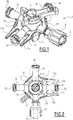
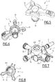
- the figures 1 to 3 represent a medical tap 1 making it possible to prepare a mixture, preferably an emulsion, intended to be injected into a patient.
- the medical valve 1 comprises a hollow body 2 from which extend three female connectors 5a, 5b and 5c and a male connector 6, preferably a luer connector.
- the body 2 comprises a barrel of cylindrical shape delimiting a central bore 200 from which extend four conduits 2a, 2b, 2c and 2d passing through the barrel and respectively passing through the connectors 5a, 5b, 5c and 6.
- the valve 1 comprises a plug 3 shown in particular on the figures 4 and 5 , rotatably mounted in the bore 200.
- the plug 3 comprises a fluid circulation channel 10 allowing the conduits 2a, 2b, 2c and 2d to be placed in communication according to a mode described below.
- the plug 3 comprises an outer cylindrical wall 14 making it possible to seal the valve 1 with the bore 200.
- An axial end of the plug 3 comprises a flange 16 allowing it to be held in the body 2 by clipping.
- the term “snap-fitting” is understood to mean the creation of a mechanical connection between the plug 3 and the body 2 causing the partial deformation of the plug 3.
- the plug 3 preferably comprises a lever 17 which can be actuated by a user allowing the rotation of the plug 3 around its central axis.
- one of the female connectors, the connector 5c in the example shown comprises a keying device 13.
- keying device is intended to denote a mechanical device making it possible to avoid connection errors in providing visual indication and defining a mechanical configuration that prevents the use of unwanted items.
- the polarizer 13 comprises two horns 13a and 13b provided on either side of the female connector 5c and which define two insertion spaces 130 and 131 located respectively between the horns 13a and 13b and the connector 5c.
- the polarizer 13 preferably makes it possible to prevent the connection of a syringe whose volume is greater than a predetermined value, thanks to the geometry of the horns 13a and 13b and the width of the spaces 130 and 131 or of a syringe provided with a means making its connection incompatible with the connector comprising this keying 13 and / or these horns 13a and 13b due to the incompatibility between this means and the mechanical configuration defined by the keying 13 and / or the horns 13a and 13b of this keying 13 Even more preferably, the keying 13 and advantageously, the horns 13a and 13b of this keying 13, make it possible to prevent the fitting of syringes 20 and 21, preferably mixing syringes, provided with a means making their connection incompatible.
- the horns 13a and 13b prevent the connection of a syringe provided with a means making its connection incompatible with the female connector 5c comprising this keying 13 and / or these horns 13a and 13b due to the incompatibility between this means and the mechanical configuration defined by the keying device and / or the horns of this keying device, they do not protrude by more than 5 mm from the end of the female connector 5c.
- the horns 13a and 13b prevent the connection of a syringe whose reservoir has a diameter greater than a threshold value corresponding to a maximum volume, preferably of a mixing syringe, they exceed the end of the female connector by more than 5 mm.
- the mixing syringe 20 is provided with means making its connection incompatible with the connector 5c comprising the polarizer 13.
- the mixing syringe 20 comprises at its end fins 20a, forming the means making the connection of the mixing syringe 20 with the connector 5c comprising a coding device.
- the mixing syringe 20 comprises at least one fin 20a, preferably at least two fins 20a. This allows the polarizer 13 to perform its function.
- the end of the mixing syringe 20 is formed by a luer connector comprising an internal male thread provided on a peripheral skirt 20b.
- the fins 20a are provided on the outer surface of the skirt 20b.
- the fins 20a create a bulk at the end of the mixing syringe 20, around the skirt 20b of the male thread of the luer connector, and which is greater than the distance D between the horns 13a and 13b.
- the mixing syringe 20 comprises at its end four fins 20a positioned at 90 ° relative to each other. This makes it possible to ensure a better dimensional balance of the body of the syringe as well as better ergonomics in terms of gripping thereof.
- the fins 20a of the mixing syringe 20 have a shape which makes it possible to generate an interference with the horns 13a and 13b of the polarizer 13.
- these fins 20a make it possible to facilitate the screwing of the mixing syringe 20. on the connectors 5a or 5b, improving the grip thereof.
- the fins are contiguous to the outer skirt 20b of the male "luer lock" thread as well as to an end conical zone 20c of the reservoir of the syringe.
- these fins 20a have an external shape of an arc of a circle. This makes it possible to position the fingers on these fins and to ensure a good grip of the mixing syringe 20 while remaining atraumatic.
- the mixing syringe 21 is also provided with such a geometry.
- the connectors 5a, 5b and 5c comprise a thread 50, to which a connection means allowing the assembly of a medical device in a sealed manner connects.
- this connection means is a luer which is the standard reference connection means in the medical field and which is screwed onto the thread 50.
- This connection means connects to the reservoir of the syringe.
- the horns 13a and 13b make it possible to size the insertion spaces 130 and 131 so that it is impossible to introduce therein syringes whose reservoir has a diameter greater than a threshold value corresponding to a maximum volume or whether it is impossible to connect a syringe due to the incompatibility between at least one means present on said syringe and the mechanical configuration defined by the horns 13a and 13b.
- the polarizer 13 makes it possible to prevent the mounting on the connector 5c of syringes having a means making their connection incompatible with the mechanical configuration defined by the polarizer or with syringes whose volume is greater than 3 ml.
- the keying 13 prevents the mounting on the connector 5c of syringes having at least one means making their connection incompatible with the mechanical configuration defined by the keying.
- the presence of fins at the end of the mixing syringes 20 and 21 makes their connection incompatible with the mechanical configuration defined by the keying device as shown on the figure. figure 9 .
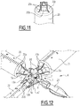
- the female connector 5c is preferably adapted to be connected with an injection syringe 22, as shown in figure 12 .
- the outer diameter of this syringe 22 and / or the size of the end of this syringe 22 allow it to be inserted into the insertion spaces 130 and 131 when it is screwed onto the connector 5c.
- the injection syringe 22 comprises at its distal end gripping gadroons 220 which have a smaller size than the distance D, the horns 13a and 13b.
- a syringe with a volume greater than 3 ml such as a mixing syringe 20, cannot be mounted on the connector 5c because of the excessively large diameter of its reservoir.
- the connectors 5a and 5b do not include a key 13 and are therefore suitable for mounting mixing syringes, as shown in figure 12 , on which two mixing syringes 20 and 21 are mounted on the connectors 5a and 5b.
- injection syringe is preferably understood to denote a syringe of small volume, that is to say of a volume of between 1 ml and 3 ml.
- mixing syringe is preferably understood to denote a syringe of large volume, that is to say a syringe with a volume greater than or equal to 10 ml.
- the female connectors 5a and 5b are contiguous, which allows the connection of two contiguous mixing syringes.
- the mixture or the emulsion into a patient while carrying out the filling of one of the mixing syringes or the injection syringe 22 or to carry out the mixing of the first and second substances. contained in one of the mixing syringes, preferably the syringe 20, while transferring the emulsion or the mixture obtained into the injection syringe 22.
- the mixture is an emulsion.
- the fluid circulation channel 10 is L-shaped, which enables the mixing syringes 20 and 21, or the mixing syringe 20 with the injection syringe 22 or the syringe to be placed in fluid communication.
- injection 22 with a downstream device such as a catheter 23 or a microcatheter.
- the valve 3 comprises visual indicators 18 making it possible to signal to the user of the valve 1 which connectors are in communication by the positioning of the valve 3.
- the indicators 18 are two arrows oriented at 90 ° with respect to one another making it possible to show the positioning of the fluid circulation channel 10.
- the plug 3 comprises, on the underside of an upper part 30 which carries the lever 17 and the indicators 18, a circular groove 31 interrupted by ribs 32 aligned with the visual indicators 18.
- the body 2 of the medical valve comprises on a upper part a means preventing a rotation of the plug 3 which would put in communication the connector to which a mixing syringe is connected and the connector to which a downstream device is connected (that is to say which would put in communication the connectors 5b and 6) .
- This means is formed by a rib 202 of curved shape and adapted to slide in the circular groove 31 between the ribs 32.
- This tap thus makes it possible either to perform a mixture or an emulsion of two substances contained in mixing syringes 20 and 21, or to fill an injection syringe 22 from one of the mixing syringes (preferably the syringe 20 ), or to inject the mixture or emulsion obtained into a patient.
- the device according to the invention is therefore preferably a 3-way, 4-port valve.
- the position of the ribs 32 is preferably linked to the position of the circular groove 31 on the plug 3.
- the ribs could therefore, in another embodiment, be positioned differently, that is to say they could not. be aligned with the visual indicators, provided that their positioning makes it possible to prevent the conduits 2b and 2d from being placed in communication.
- the medical valve 1 comprises at least two gripping zones adapted to the positioning of a finger. These gripping zones make it possible to grip the valve 1 more effectively and thus facilitate its handling during the steps of connecting or disconnecting the syringes 20, 21 and 22 or during the orientation of the plug 3 allowing the communication of such or such. such connector.
- the valve 1 comprises four gripping zones 15 formed by flat circular shapes projecting from the body 2. These gripping zones 15 are distributed between the connectors 5a, 5b, 5c and 6.
- the medical valve 1 comprises a reinforcing flange 7 integral with at least two of the connectors of the medical valve 1.
- the reinforcing flange 7 is spaced from the central body 2 to form a perforated zone 9 around the central body 2. The fact of moving the reinforcing collar 7 away from the central axis of the valve 1 makes it possible to move away the zone of stress concentrations and to reduce the effects of the stresses.
- valve 1 If the applied stress is high and if in addition a phenomenon of chemical attack by an oily solution is added, the valve 1 can become directly brittle without going through the plastic deformation phase. This is the case with most standard infusion valves used in chemoembolization (c-TACE) procedures.
- the perforated zone 9 thus formed prevents the generation of shrinkages inside the body 2.
- the reinforcing flange 7 is therefore not in direct contact with the bore 200 in which the plug 3 is rotatably mounted.
- the reinforcing collar 7 is integral with three or four connectors of the medical valve 1.
- the reinforcing collar 7 is integral with the four connectors 5a, 5b, 5c and 6 and forms a complete belt around the body. 2, thus improving the strength of the valve 1.
- the perforation 9 which will in this embodiment prevent any contact of the collar with the central barrel of the valve, makes it possible to avoid the appearance of sinkings as much as possible.
- the medical valve 1 can include only two female connectors and one male connector.
- the intersection between the reinforcing flange 7 and each connector is away from the thread 50 of the connector, or more generally from the functional zone of the connector, which is most often the distal end of this connector, since the zone functional is the connection port on which or in which is inserted, for example, a syringe or the locking ring of a tubing or a catheter.
- the reinforcing flange 7 is made of the same material as the body 2.
- the medical valve 1 is formed in one piece and in the same material.
- the reinforcing flange 7 is made of a material different from the body 2 and the plug 3.
- the medical valve 1 is formed in one piece, but involves an operation of overmolding the flange 7, which presents the advantage of strengthening the mechanical strength of the latter.
- the overmolding of the reinforcing flange 7 is made of “filled” plastic materials.
- filled plastic material is understood to mean a material in which a solid, immiscible substance called “filler” has been dispersed at the time of injection.
- the filler is chosen from the compounds of the following list: mineral fillers in powder form such as synthetic silica, organic fillers such as wood flour or fruit peel or cellulose pulp , fibrous reinforcing fillers such as glass fibers and non-fibrous reinforcing fillers such as hollow glass microspheres or synthetic silica.
- the fibrous reinforcing fillers make it possible to improve the mechanical characteristics, the thermal resistance and the dimensional stability of the material.
- the reinforcing collar 7 is overmolded on the body 2 with a material loaded with fibers such as glass fibers.
- the reinforcing flange 7 has a width L7 greater than its thickness e7, which thus makes it possible to improve the moment of inertia and therefore the mechanical strength of the valve 1.
- the reinforcing flange 7 preferably has a width L7 3 to 10 times, preferably 3 to 7 times, more preferably 3 to 5 times greater than its thickness e7.
- the term “perforated zone” is understood to mean a zone of material void in the form of a crown between the barrel of the body 2 of the valve 1 and the reinforcing flange 7.
- said crown has an internal radius r a , equal to the external radius R f of the barrel of the body 2 and an external radius R a equal to the internal radius r c of the reinforcement flange 7.
- the difference between R a and r a gives the width l a of the perforated zone 9.
- the width l a of the perforated zone 9 is preferably from 0.1 to 4 mm, more preferably from 1 to 2.5 mm and even more preferably from 1.5 to 2.5 mm.
- the reinforcing flange 7 is a ring of plastic material or of another material as described below, providing the connection between at least two luer ports.
- the crown shape makes it possible to dissipate the forces as well as possible without generating a zone of stress concentration.
- the internal radius of the crown r c is equal to the external radius of the perforation R a .
- the width of the crown L c is preferably from 1 to 20 mm, more preferably from 2 to 10 mm and even more preferably from 3 to 6 mm.
- the thickness e c of this ring of plastic material or of another material as described below is preferably from 0.5 to 8 mm, more preferably from 1 to 5 mm and even more preferably from 1.5 to 2.5 mm.
- the width l a of the perforated zone 9 between the reinforcing flange 7 and the barrel of the body 2 is preferably equal to the thickness e7 of the reinforcing flange 7.
- This perforation zone 9 is produced in the plastic injection tooling by a molding core.
- This molding core made of a steel alloy undergoes very significant forces (pressure) during the injection phases of the plastic. These pressures can be from 500 to 2,500 bars and more generally from 500 to 1,500 bars.
- pressure forces
- a temperature factor of the plastic material injected into the cavity and coming into contact with the molding core from 150 to 300 ° C. This temperature causes strong expansion stresses on this molding core.
- the even more preferred width l a of 1.5 to 2.5 mm makes it possible to maintain optimum mechanical strength of the molding core.
- the collar 7 must not have any surface in contact with the barrel of the body 2 of the valve 1.
- the gripping means 15 are located on the reinforcing flange 7.
- the horns 13a and 13b of the polarizer 13 extend from the reinforcing flange 7.
- the horns 13a and 13b may not be connected to the reinforcing flange 7 and s' extend, for example from connector 5c or body 2.
- the medical valve 1 may not include gripping means or horns forming a keying device provided on the reinforcing collar 7.
- the body 2, the plug 3 and / or the reinforcing flange 7 which make up the medical valve 1 are made from one or more materials which better withstand mechanical and chemical stresses.
- the body 2 and the reinforcing flange 7 are made of a material different from the plug 3.
- the mechanical stresses are essentially the deformation by shearing and the pressure exerted on the valve 1 during its manufacture and / or use.
- the material of manufacture of the tap 1 must be resistant to any pharmaceutical product, including oily products.
- the material should be resistant to Lipiodol®.
- the material of the body 2 and / or of the reinforcing flange 7 must be characterized by a high modulus of mechanical resistance (Young's modulus).
- the medical valve 1, preferably its body 2 and its reinforcing collar 7, is made from materials chosen from the following list: acrylonitrile butadiene styrene (ABS), methymethacrylate-acrylonitrile-butadiene styrene (MABS), polyester, polycarbonates (PC), polycarbonate alloys, polysulfones, polyurethanes, polyetherketonketone (PEKK), polyetheretherketone (PEEK), polyaryletherketones (PAEK), polymethylmetacrylate (PMMA), polyetherimides, polyamides, polyamides, PA12 (PA11), preferably TPX), polysulfone (PSU), copolymers of cycloolefins (COC), polymers of cycloolefins (COP), fluoroplastics other than polytetrafluoroethylene (PTFE), phosphoenolpyruvate (PEP), and combinations of these materials (for example, ABS-PC) .
- the medical valve 1, more preferably its body 2 and its reinforcing flange 7, is made from materials chosen from the following list: acrylonitrile butadiene styrene (ABS), methymethacrylate-acrylonitrile-butadiene styrene (MABS), polycarbonates (PC), polyetheretherketone (PEEK), polymethyl methacrylate (PMMA), polyamides (PA), preferably PA11 and PA12, polymethylpentene (TPX), polysulfone (PSU), copolymers of cycloolefins (COC), polymers of cycloolefins (COP) .
- ABS acrylonitrile butadiene styrene
- MABS methymethacrylate-acrylonitrile-butadiene styrene
- PC polycarbonates
- PEEK polyetheretherketone
- PMMA polymethyl methacrylate
- PA polyamides
- PA11 and PA12 polymethylpen
- the medical valve 1, more preferably its body 2 and its reinforcing collar 7, is made from materials chosen from the following list: polyetheretherketone (PEEK), polymethyl methacrylate (PMMA), polyamides (PA ), preferably PA11 and PA12, polymethylpentene (TPX) and polysulfone (PSU).
- PEEK polyetheretherketone
- PMMA polymethyl methacrylate
- PA polyamides
- PA11 and PA12 preferably PA11 and PA12
- TPX polymethylpentene
- PSU polysulfone
- the medical tap 1 comprises polyamide or consists of polyamide.
- the plug 3 of the valve is made of a material softer than the body 2 and / or the reinforcing flange 7 of this valve.
- the plug 3 of the tap is preferably made from materials chosen from the following list: polyethylene (PE), polypropylene (PP), polyoxymethylene (POM) or polybutylene terephthalate (PBT). This material must allow the plug 3 to be able to conform slightly in the body 2 of the valve.
- the body 2 and that the plug 3 are made of different materials makes it possible to improve the rotational properties of the plug 3 in the body 2 of the valve.
- the plug 3 is more preferably made of POM.
- the female connectors 5a, 5b and 5c are input ports, while the male connector 6 is an output port.
- the male connector 6 comprises a locking ring 8 which is fixed. This ring is therefore integral with the connector 6 and more generally with the body 2 of the valve 1.
- the male connector 6 comprises a locking ring 8 which is mounted by clipping on the distal end of the male connector 6.
- the locking ring 8 is movable and makes it possible to strengthen the connection of the connector.
- male 6 with a female connector of a downstream device for example a catheter or a micro-catheter. More preferably, the locking ring 8 rotates on the axis of the male connector 6, which itself remains fixed. This has the advantage of making the connection easier to handle while reducing the risk of disconnection.
- the medical valve 1 makes it possible to form a preparation kit K of a product to be injected, preferably a mixture or an emulsion, with two mixing syringes 20 and 21 and an injection syringe 22.
- the female connectors 5a and 5b are respectively connected to a first mixing syringe 20 and to a second mixing syringe 21, and the female connector 5c comprising the polarizer 13 is connected to an injection syringe 22.
- the preparation kit can also comprise a downstream device, such as a catheter 23 or a microcatheter allowing the injection into a patient of the product to be injected contained in the injection syringe 22.
- a downstream device such as a catheter 23 or a microcatheter allowing the injection into a patient of the product to be injected contained in the injection syringe 22.
- the catheter 23 is mounted and locked on. the male connector 6 using the locking ring 8.
- the connector which is on the channel in communication with a downstream device such as a catheter 23 or a micro-catheter, which comprises a keying device 13.
- a downstream device such as a catheter 23 or a micro-catheter, which comprises a keying device 13.
- the keying device prevents the connection of at least one of the elements of the kit, even more preferably of at least two of the elements of the kit.
- the polarizer 13, according to the present invention prevents the connection of the mixing syringes 20, 21.
- the elements of the kit are provided with means making their connection incompatible with the connector comprising the keying device.
- These means making the connection of elements of the kit incompatible with the connector comprising the keying device are preferably fins located at the end of said elements of the kit.
- the preparation kit may also include accessories for sampling solutions to facilitate the filling of the mixing syringes 20 and 21.
- the preparation kit K makes it possible to implement a method of preparing a mixture or an emulsion intended for injection into a patient. This method includes the following steps. In a first step, two mixing syringes 20 and 21 are mounted on two corresponding female connectors 5a and 5b.
- the injection syringe 22 is mounted on the female connector 5c comprising the key 13.
- the mixing syringes 20 and 21 contain as contents respectively an aqueous solution and an oil, preferably an iodized oil.
- Said aqueous solution comprises at least one anti-cancer agent and optionally at least one densifying agent.
- the anticancer agent which the aqueous solution present in one of the two mixing syringes can comprise is chosen from anthracyclines and more preferably from doxorubicin, epirubicin, nemorubicin and idarubicin.
- the aqueous solution can thus further comprise a densifying agent, preferably at least one nonionic iodinated contrast product.
- the nonionic iodine product which can be used as a densifying agent, is preferably chosen from iobitridol (Xenetix®), iopamidol (Iopamiron®, Isovue®), iomeprol (Iomeron®), l 'ioversol (Optiray®, Optiject®), iohexol (Omnipaque®), iopentol (Imagopaque®), ioxitol (Oxilan®), iopromide (Ultravist®), metrizamide (Amipaque®), l iosarcol (Melitrast®), iotrolan (Isovist®), iodixanol (Visipaque®), iosimenol and iosimide (Univist®) and a mixture thereof.
- Iobitridol is the preferred nonionic iodine
- the iodized oil which one of the mixing syringes may contain comprises or consists of derivatives of iodinated fatty acids, preferably ethyl esters of iodinated fatty acids, more preferably ethyl esters of iodinated fatty acids of carnation oil, olive oil, rapeseed oil, peanut oil, soybean oil or walnut oil, even more preferably ethyl esters of iodinated fatty acids of carnation oil or olive oil. More preferably, this iodized oil comprises or consists of ethyl esters of iodinated fatty acids of carnation oil also called black poppy or Papaver somniferum var. nigrum.
- a third step consists in mixing the aqueous solution contained in the mixing syringe 20 with the oil contained in the mixing syringe 21 after having positioned the plug 3 so as to place the mixing syringes 20 and 21 in communication via conduits 2a and 2b and by moving the pistons of the mixing syringes 20 and 21 back and forth until a mixture or an emulsion is obtained.
- part or all of the mixture or of the emulsion obtained in the mixing step is transferred into the injection syringe 22, after having positioned the plug 3 so as to place the syringe in communication. of mixing 20, in which part or all of the mixture or of the emulsion obtained in the mixing step has been transferred, with the injection syringe 22 via the conduit 2a and the conduit 2c.
- the fourth step is carried out as soon as the user of the tap visually estimates that the mixture or the emulsion is homogeneous.
- the catheter 23 is mounted either simultaneously with the mixing syringes 20 and 21 and / or with the injection syringe 22, either after completion of the mixing step, or after the step of transferring part of the mixture or of the emulsion in the injection syringe 22.
- the catheter 23 is mounted on the male connector 6, after completion of this fourth transfer step.
- an additional step of mixing the mixture or the emulsion obtained in the third step can be carried out, in the event that the user visually considers that the mixture or emulsion has out of phase.
- the communication of the mixing syringe 20 with the injection syringe 22 or of the injection syringe 22 with the catheter 23 is effected by adequately positioning the fluid circulation channel 10 of the plug 3 by a movement of rotation of the lever 17.
- the correct positioning of the plug 3 adapted to the preparation step to be performed is checked using the arrow indicators 18.
- the plug 3 is positioned so as to place the connectors 5a and 5b in fluid communication, as indicated by the arrows 18, to allow mixing of the contents of the mixing syringes 20 and 21.
- the polarizer 13 makes it possible to eliminate the risk that a mixing syringe 20 or 21 is connected to the connector 5c intended for the injection syringe 22 and of errors being made in the preparation of the mixture which is to be injected into the patient. Thanks to the keying 13, there is only one female connector on which the injection syringe 22 can be mounted, and the mixing syringes 20 and 21 can only be mounted on the remaining female connectors, which are positioned so contiguous way. This ensures the reliability of the medical valve 1.
- the injection syringe 22 is mounted on one of the female connectors in place of one of the mixing syringes 20 and 21 once. that the mixture or emulsion has been prepared and transferred to one of the mixture syringes 20 and 21.
Landscapes
- Health & Medical Sciences (AREA)
- Heart & Thoracic Surgery (AREA)
- Hematology (AREA)
- Engineering & Computer Science (AREA)
- Anesthesiology (AREA)
- Biomedical Technology (AREA)
- Life Sciences & Earth Sciences (AREA)
- Animal Behavior & Ethology (AREA)
- General Health & Medical Sciences (AREA)
- Public Health (AREA)
- Veterinary Medicine (AREA)
- Pulmonology (AREA)
- Vascular Medicine (AREA)
- Infusion, Injection, And Reservoir Apparatuses (AREA)
- Materials For Medical Uses (AREA)
Claims (15)
- Medizinischer Absperrhahn (1), umfassend:- einen Körper (2), der mit mindestens zwei Buchsenverbindern (5a, 5b) und einem Steckverbinder (6) versehen ist,- einen in dem Körper (2) montierten beweglichen Hahnkegel (3), der mit einem Drehhebel (17) versehen ist und einen Fluidumlaufkanal (10) umfasst, und- einen Verstärkungsbund (7), der fest mit mindestens zwei der Verbinder (5a, 5b, 5c, 6) verbunden ist,dadurch gekennzeichnet, dass der Verstärkungsbund (7) unter Bildung eines durchbrochenen Bereichs (9) um den mittleren Körper (2) von dem Körper (2) beabstandet ist.
- Medizinischer Absperrhahn nach Anspruch 1, dadurch gekennzeichnet, dass er vier Verbinder umfasst, drei davon Buchsenverbinder (5a, 5b, 5c), und dass der Verstärkungsbund (7) fest mit drei oder vier Verbindern (5a, 5b, 5c, 6) verbunden ist.
- Medizinischer Absperrhahn nach einem der vorhergehenden Ansprüche, dadurch gekennzeichnet, dass er mindestens zwei Greifmittel (15) umfasst, die zur Positionierung eines Fingers ausgeführt sind, und dass die Greifmittel (15) an dem Verstärkungsbund (7) angeordnet sind.
- Medizinischer Absperrhahn nach einem der vorhergehenden Ansprüche, dadurch gekennzeichnet, dass der Verstärkungsbund (7) in demselben Material wie der Körper (2) ausgeführt ist.
- Medizinischer Absperrhahn nach einem der Ansprüche 1 bis 3, dadurch gekennzeichnet, dass der Verstärkungsbund (7) in einem Material ausgeführt ist, das sich von dem des Körpers (2) und dem des Hahnkegels (3) unterscheidet.
- Medizinischer Absperrhahn nach Anspruch 5, dadurch gekennzeichnet, dass der Verstärkungsbund (7) in einem faserverstärkten Material ausgeführt ist, das an den Körper (2) angeformt ist.
- Medizinischer Absperrhahn nach einem der vorhergehenden Ansprüche, dadurch gekennzeichnet, dass der Hahnkegel (3) aus einem Material ausgeführt ist, das weicher als der Körper (2) und/oder der Verstärkungsbund (7) ist.
- Medizinischer Absperrhahn nach einem der vorhergehenden Ansprüche, dadurch gekennzeichnet, dass der Verstärkungsbund (7) eine Breite (L7) hat, die größer als seine Dicke (e7) ist, vorzugsweise eine Breite (L7), die um ein 3- bis 10-Faches größer als seine Dicke (e7) ist.
- Medizinischer Absperrhahn nach einem der vorhergehenden Ansprüche, dadurch gekennzeichnet, dass mindestens einer der Buchsenverbinder (5c) zur Aufnahme einer Injektionsspritze (22) ausgeführt ist und eine Unverwechselbarkeitseinrichtung (13) umfasst, die es gestattet, das Montieren einer Mischspritze (20, 21) an diesen Verbinder (5c) zu verhindern, und dass diese Unverwechselbarkeitseinrichtung (13) aus zwei Vorsprüngen (13a, 13b) gebildet ist, die sich von dem Verstärkungsbund (7) erstrecken und beiderseits des Buchsenverbinders (5c) vorgesehen sind, der zur Aufnahme einer Injektionsspritze (22) ausgeführt ist, und bezüglich dieses Verbinders (5c) Einführungsräume (130, 131) bilden.
- Medizinischer Absperrhahn nach Anspruch 9, dadurch gekennzeichnet, dass die Vorsprünge (13a, 13b) das Verhindern der Montage von Spritzen (20, 21) gestatten, die mit einem Mittel (20a) versehen sind, das ihre Verbindung mit dem für die Aufnahme einer Injektionsspritze (22) ausgeführten Buchsenverbinder (5c) inkompatibel macht.
- Kit (K) zur Herstellung eines zu injizierenden Produkts, dadurch gekennzeichnet, dass es Folgendes umfasst:- einen medizinischen Absperrhahn (1) nach einem der vorhergehenden Ansprüche,- zwei Mischspritzen (20, 21), die dazu ausgeführt sind, mit einem ersten und mit einem zweiten Buchsenverbinder (5a, 5b) des Absperrhahns (1) verbunden zu werden, und- eine Injektionsspritze (22), die dazu ausgeführt ist, mindestens einen Teil des durch das Mischen der Inhalte der Mischspritzen (20, 21) erhaltenen Produkts zu sammeln, wobei das Mischen durch eine Hin- und Herbewegung der Kolben der Mischspritzen (20, 21) erfolgt, und dazu ausgeführt ist, mit einem der Buchsenverbinder (5c) des Absperrhahns (1) verbunden zu werden.
- Herstellungs-Kit nach Anspruch 11, dadurch gekennzeichnet, dass einer der Buchsenverbinder (5c) des Absperrhahns (1) eine Unverwechselbarkeitseinrichtung (13) umfasst und dass die Mischspritzen (20, 21) ein Mittel (20a) umfassen, das ihre Verbindung mit dem Buchsenverbinder (5c) inkompatibel macht.
- Herstellungs-Kit nach Anspruch 12, dadurch gekennzeichnet, dass die Mischspritzen (20, 21) Rippen (20a) an ihrem Ende umfassen.
- Verfahren zur Herstellung eines Gemischs oder einer Emulsion, das bzw. die für die Injektion in einen Patienten bestimmt ist, dadurch gekennzeichnet, dass es Schritte umfasst, die aus Folgendem bestehen:a) Verbinden von zwei Mischspritzen (20, 21) mit zwei entsprechenden Buchsenverbindern (5a, 5b) eines medizinischen Absperrhahns (1) nach einem der Ansprüche 1 bis 10,b) Mischen einer in einer der Mischspritzen (20) enthaltenen wässrigen Lösung mit einem in der anderen Mischspritze (21) enthaltenen Öl, nachdem ein Hahnkegel (3) des medizinischen Absperrhahns (1) so positioniert worden ist, dass die Mischspritzen (20, 21) miteinander in Fluidverbindung gebracht worden sind, und unter Durchführung einer Hin- und Herbewegung der Kolben dieser Mischspritzen (20, 21), bis ein Gemisch oder eine Emulsion erhalten worden ist,c) Verbinden einer Injektionsspritze (22) mit einem spezifischen Verbinder (5c) des medizinischen Absperrhahns (1) oder anstelle der Mischspritzen (20, 21),d) Transferieren eines Teils oder der Gesamtheit des in Schritt b) erhaltenen Gemischs oder der in Schritt b) erhaltenen Emulsion in die Injektionsspritze (22), nachdem der Hahnkegel (3) so positioniert worden ist, dass eine der Mischspritzen (20, 21) mit der Injektionsspritze (22) in Fluidverbindung gebracht wird.
- Herstellungsverfahren nach Anspruch 14, dadurch gekennzeichnet, dass es ferner einen zusätzlichen Schritt umfasst, der darin besteht, eine stromabwärtige Vorrichtung (23), vorzugsweise einen Katheter oder einen Mikro-Katheter, mit einem Steckverbinder (6) des medizinischen Absperrhahns (1) zu verbinden, wobei dieser Schritt entweder gleichzeitig mit dem Schritt a) oder nach Schritt b) oder gleichzeitig mit Schritt c) oder nach Schritt d) erfolgt.
Applications Claiming Priority (2)
| Application Number | Priority Date | Filing Date | Title |
|---|---|---|---|
| FR1553325A FR3034997B1 (fr) | 2015-04-15 | 2015-04-15 | Robinet medical, kit comprenant un tel robinet et methode de preparation d'un melange ou d'une emulsion. |
| PCT/EP2016/058453 WO2016166346A1 (fr) | 2015-04-15 | 2016-04-15 | Robinet medical, kit comprenant un tel robinet et methode de preparation d'un melange ou d'une emulsion. |
Publications (2)
| Publication Number | Publication Date |
|---|---|
| EP3283162A1 EP3283162A1 (de) | 2018-02-21 |
| EP3283162B1 true EP3283162B1 (de) | 2021-02-24 |
Family
ID=54260841
Family Applications (1)
| Application Number | Title | Priority Date | Filing Date |
|---|---|---|---|
| EP16717351.7A Active EP3283162B1 (de) | 2015-04-15 | 2016-04-15 | Medizinisches ventil, kit mit solch einem ventil und verfahren zur herstellung eines gemisches oder einer emulsion |
Country Status (13)
| Country | Link |
|---|---|
| US (1) | US10525251B2 (de) |
| EP (1) | EP3283162B1 (de) |
| JP (1) | JP6751103B2 (de) |
| KR (1) | KR102607042B1 (de) |
| CN (1) | CN107530535A (de) |
| BR (1) | BR112017021923A2 (de) |
| CA (1) | CA2982611A1 (de) |
| ES (1) | ES2856060T3 (de) |
| FR (1) | FR3034997B1 (de) |
| MX (1) | MX2017013287A (de) |
| PH (1) | PH12017501866A1 (de) |
| RU (1) | RU2017136138A (de) |
| WO (1) | WO2016166346A1 (de) |
Families Citing this family (10)
| Publication number | Priority date | Publication date | Assignee | Title |
|---|---|---|---|---|
| JP6707075B2 (ja) * | 2015-03-11 | 2020-06-10 | テルモ株式会社 | コネクタ及び医療機器セット |
| US11890405B2 (en) * | 2016-11-27 | 2024-02-06 | Albert A. Mikhail | Multi-port syringe system and method for use with a urinary catheter |
| US10737057B1 (en) * | 2016-11-27 | 2020-08-11 | Albert A. Mikhail | Multiport syringe system for use with a urinary catheter |
| CA3102804A1 (en) | 2018-06-05 | 2019-12-12 | Deka Products Limited Partnership | Reservoir devices, methods and systems |
| MX2021003118A (es) * | 2018-09-19 | 2021-08-19 | Deroyal Ind Inc | Sistema de conexión de tubos para terapia de heridas con presión negativa. |
| FR3100457B1 (fr) | 2019-09-05 | 2021-09-17 | Maison Hendricks | seringue destinée à injecter un liquide additionnel dans un robinet multivoies |
| WO2022065350A1 (ja) * | 2020-09-24 | 2022-03-31 | ニプロ株式会社 | 薬剤乳化器具 |
| FR3134316B1 (fr) | 2022-04-11 | 2024-04-12 | Guerbet Sa | Robinet médical |
| EP4299080A1 (de) | 2022-06-28 | 2024-01-03 | Guerbet | Röntgendichtes monomer und embolisationsmikrosphären, die es enthalten |
| WO2025194262A1 (en) * | 2024-03-21 | 2025-09-25 | Abk Biomedical Incorporated | Valved container for dispensing radioactive microparticles |
Family Cites Families (28)
| Publication number | Priority date | Publication date | Assignee | Title |
|---|---|---|---|---|
| US2703586A (en) * | 1952-10-02 | 1955-03-08 | Daly Merritt & Sullivan Inc | Valve |
| US3157201A (en) * | 1962-04-12 | 1964-11-17 | Cardiosonics Medical Instr Com | Fluid exchange valve |
| US3161195A (en) * | 1963-01-29 | 1964-12-15 | American Cyanamid Co | Two-compartment aspirating hypodermic syringe |
| US3957082A (en) * | 1974-09-26 | 1976-05-18 | Arbrook, Inc. | Six-way stopcock |
| US4217933A (en) * | 1979-05-15 | 1980-08-19 | Mayer Robert B | Diverter valve for septic systems |
| US4372294A (en) * | 1980-09-25 | 1983-02-08 | The Massachusetts General Hospital | Method and apparatus for radiolabeling red blood cells |
| US4807666A (en) * | 1987-08-26 | 1989-02-28 | North American Instruments Corp. | Stopcock valve for high pressure applications |
| JP2577239Y2 (ja) * | 1991-07-12 | 1998-07-23 | 仁 加藤 | 薬液混合用連結管 |
| FR2749169B1 (fr) | 1996-06-04 | 1998-08-21 | Delab | Procede pour constituer une preparation injectable et dispositif pour la mise en oeuvre de ce procede |
| US5868250A (en) * | 1996-09-26 | 1999-02-09 | Brackett; Fred | Tray for holding medical instruments |
| FR2804609B1 (fr) | 2000-02-08 | 2002-08-30 | Sedat | Dispositif de distribution pour un reseau de transport d'un fluide medical |
| US7172572B2 (en) * | 2001-10-04 | 2007-02-06 | Boston Scientific Scimed, Inc. | Manifold system for a medical device |
| US6880808B2 (en) | 2002-05-03 | 2005-04-19 | Acist Medical Systems, Inc. | Gamma-stable high pressure stopcock |
| DE20302819U1 (de) * | 2003-02-21 | 2003-05-08 | Filtertek, S.A., Plailly | Filter für medizinische und Laborzwecke, insbesondere für Blutanalysen u.dgl. |
| EP1833452A1 (de) * | 2004-11-23 | 2007-09-19 | Smith and Nephew, Inc. | Kompositionsmischer |
| DE602005013823D1 (de) * | 2005-01-03 | 2009-05-20 | Mark Indigne | Absperrhahnverschlussstopfen |
| US9050401B2 (en) * | 2010-05-19 | 2015-06-09 | Angioadvancements, Llc | System for controlled delivery of medical fluids |
| GB0614452D0 (en) * | 2006-07-20 | 2006-08-30 | Young Peter J | Connector system |
| EP2078536A4 (de) | 2006-10-18 | 2015-02-18 | Terumo Corp | Medizinische vorrichtung |
| US20080108954A1 (en) | 2006-11-02 | 2008-05-08 | Jean-Marie Mathias | Flow Controllers |
| US7785312B2 (en) * | 2008-02-06 | 2010-08-31 | Intravena, Llc | Convenience IV kits and methods of use |
| CA2768451C (en) * | 2009-07-20 | 2017-11-21 | David R. Duncan | Multi-port stopcock valve and flow designating system |
| US9814870B2 (en) * | 2010-08-17 | 2017-11-14 | Becton, Dickinson And Company | Non-luer connectors |
| US11759572B2 (en) * | 2011-01-17 | 2023-09-19 | Aktivax, Inc. | Aseptic cartridge and dispenser arrangement |
| DE102011108787A1 (de) * | 2011-07-29 | 2013-01-31 | Fresenius Medical Care Deutschland Gmbh | Medizinischer Port, Blutschlauch zur Verwendung bei einer extrakorporalen Blutbehandlung sowie medizinische Behandlungsvorrichtung |
| DE102012112212A1 (de) * | 2012-12-13 | 2014-07-03 | Hans-Jürgen Hopf | Anschlusssystem mit Überwurfmutter |
| CN105163796B (zh) * | 2013-03-15 | 2018-06-01 | Icu医学有限公司 | 医用连接器 |
| DE202013103615U1 (de) * | 2013-08-12 | 2013-09-02 | Hans-Jürgen Hopf | Verbindungssystem mit Verwechslungsschutz für den Einsatz in der Medizin und Medizintechnik |
-
2015
- 2015-04-15 FR FR1553325A patent/FR3034997B1/fr active Active
-
2016
- 2016-04-15 US US15/565,764 patent/US10525251B2/en active Active
- 2016-04-15 BR BR112017021923-9A patent/BR112017021923A2/pt not_active Application Discontinuation
- 2016-04-15 CA CA2982611A patent/CA2982611A1/fr not_active Abandoned
- 2016-04-15 EP EP16717351.7A patent/EP3283162B1/de active Active
- 2016-04-15 CN CN201680021379.1A patent/CN107530535A/zh active Pending
- 2016-04-15 JP JP2017553348A patent/JP6751103B2/ja active Active
- 2016-04-15 KR KR1020177029751A patent/KR102607042B1/ko active Active
- 2016-04-15 RU RU2017136138A patent/RU2017136138A/ru not_active Application Discontinuation
- 2016-04-15 MX MX2017013287A patent/MX2017013287A/es unknown
- 2016-04-15 WO PCT/EP2016/058453 patent/WO2016166346A1/fr not_active Ceased
- 2016-04-15 ES ES16717351T patent/ES2856060T3/es active Active
-
2017
- 2017-10-11 PH PH12017501866A patent/PH12017501866A1/en unknown
Non-Patent Citations (1)
| Title |
|---|
| None * |
Also Published As
| Publication number | Publication date |
|---|---|
| WO2016166346A1 (fr) | 2016-10-20 |
| EP3283162A1 (de) | 2018-02-21 |
| JP6751103B2 (ja) | 2020-09-02 |
| CA2982611A1 (fr) | 2016-10-20 |
| US10525251B2 (en) | 2020-01-07 |
| BR112017021923A2 (pt) | 2018-07-03 |
| US20180117297A1 (en) | 2018-05-03 |
| MX2017013287A (es) | 2018-01-26 |
| JP2018511419A (ja) | 2018-04-26 |
| CN107530535A (zh) | 2018-01-02 |
| ES2856060T3 (es) | 2021-09-27 |
| KR102607042B1 (ko) | 2023-11-29 |
| RU2017136138A (ru) | 2019-04-12 |
| KR20170137773A (ko) | 2017-12-13 |
| FR3034997B1 (fr) | 2021-04-16 |
| FR3034997A1 (fr) | 2016-10-21 |
| RU2017136138A3 (de) | 2019-08-08 |
| PH12017501866A1 (en) | 2018-03-05 |
Similar Documents
| Publication | Publication Date | Title |
|---|---|---|
| EP3283162B1 (de) | Medizinisches ventil, kit mit solch einem ventil und verfahren zur herstellung eines gemisches oder einer emulsion | |
| EP3283799B1 (de) | Medizinisches ventil, kit mit solch einem ventil und verfahren zur herstellung eines gemisches oder einer emulsion | |
| EP2950876B1 (de) | Verbesserter medizinischer verbinder | |
| CA2344214C (fr) | Seringues pour l'administration de formulations pateuses ou semi-solides | |
| FR2602420A1 (fr) | Capsules pour matieres de reconstitution dentaire | |
| EP2861276B1 (de) | Anordnung zur injektion eines zähflüssigen produkts | |
| FR2931681A1 (fr) | Seringue a embout universel | |
| FR2933307A1 (fr) | Dispositif d'injection d'un fluide a usage medicale | |
| EP0648513B1 (de) | Infusionsvorrichtung | |
| CH570169A5 (en) | Rear filling liq syringe distributor - with filling device | |
| FR2931684A1 (fr) | Ligne de perfusion pour l'administration de liquides de traitement medical, tels que des produits de chimiotherapie, a un patient, et procede d'utilisation d'une telle ligne de perfusion | |
| FR2776742A1 (fr) | Perfectionnement pour valve a seuil | |
| FR2966738A1 (fr) | Seringue melangeuse | |
| FR3041717A1 (fr) | Cheville pour la fixation d'une piece a un materiau support creux ou plein | |
| EP4587097A1 (de) | Kit mit einer phiole und einem männlichen verbinder | |
| WO2013186300A2 (fr) | Ensemble d'injection de produit liquide et visqueux | |
| FR3100457A1 (fr) | seringue destinée à injecter un liquide additionnel dans un robinet multivoies | |
| WO2001074423A1 (fr) | Seringue d'injection d'un melange extemporane | |
| FR2717696A1 (fr) | Seringue à double orifice. | |
| FR2943759A1 (fr) | Pompe a graisse a main a fiabilite amelioree | |
| HK1242234A1 (en) | Medical stopcock, kit comprising such a stopcock, and method for preparing a mixture or an emulsion |
Legal Events
| Date | Code | Title | Description |
|---|---|---|---|
| STAA | Information on the status of an ep patent application or granted ep patent |
Free format text: STATUS: THE INTERNATIONAL PUBLICATION HAS BEEN MADE |
|
| PUAI | Public reference made under article 153(3) epc to a published international application that has entered the european phase |
Free format text: ORIGINAL CODE: 0009012 |
|
| STAA | Information on the status of an ep patent application or granted ep patent |
Free format text: STATUS: REQUEST FOR EXAMINATION WAS MADE |
|
| 17P | Request for examination filed |
Effective date: 20171114 |
|
| AK | Designated contracting states |
Kind code of ref document: A1 Designated state(s): AL AT BE BG CH CY CZ DE DK EE ES FI FR GB GR HR HU IE IS IT LI LT LU LV MC MK MT NL NO PL PT RO RS SE SI SK SM TR |
|
| AX | Request for extension of the european patent |
Extension state: BA ME |
|
| DAV | Request for validation of the european patent (deleted) | ||
| DAX | Request for extension of the european patent (deleted) | ||
| GRAP | Despatch of communication of intention to grant a patent |
Free format text: ORIGINAL CODE: EPIDOSNIGR1 |
|
| STAA | Information on the status of an ep patent application or granted ep patent |
Free format text: STATUS: GRANT OF PATENT IS INTENDED |
|
| INTG | Intention to grant announced |
Effective date: 20200707 |
|
| GRAJ | Information related to disapproval of communication of intention to grant by the applicant or resumption of examination proceedings by the epo deleted |
Free format text: ORIGINAL CODE: EPIDOSDIGR1 |
|
| STAA | Information on the status of an ep patent application or granted ep patent |
Free format text: STATUS: REQUEST FOR EXAMINATION WAS MADE |
|
| GRAP | Despatch of communication of intention to grant a patent |
Free format text: ORIGINAL CODE: EPIDOSNIGR1 |
|
| STAA | Information on the status of an ep patent application or granted ep patent |
Free format text: STATUS: GRANT OF PATENT IS INTENDED |
|
| INTC | Intention to grant announced (deleted) | ||
| INTG | Intention to grant announced |
Effective date: 20201106 |
|
| GRAS | Grant fee paid |
Free format text: ORIGINAL CODE: EPIDOSNIGR3 |
|
| GRAA | (expected) grant |
Free format text: ORIGINAL CODE: 0009210 |
|
| STAA | Information on the status of an ep patent application or granted ep patent |
Free format text: STATUS: THE PATENT HAS BEEN GRANTED |
|
| AK | Designated contracting states |
Kind code of ref document: B1 Designated state(s): AL AT BE BG CH CY CZ DE DK EE ES FI FR GB GR HR HU IE IS IT LI LT LU LV MC MK MT NL NO PL PT RO RS SE SI SK SM TR |
|
| REG | Reference to a national code |
Ref country code: CH Ref legal event code: EP |
|
| REG | Reference to a national code |
Ref country code: AT Ref legal event code: REF Ref document number: 1363702 Country of ref document: AT Kind code of ref document: T Effective date: 20210315 |
|
| REG | Reference to a national code |
Ref country code: IE Ref legal event code: FG4D Free format text: LANGUAGE OF EP DOCUMENT: FRENCH |
|
| REG | Reference to a national code |
Ref country code: DE Ref legal event code: R096 Ref document number: 602016053062 Country of ref document: DE |
|
| REG | Reference to a national code |
Ref country code: LT Ref legal event code: MG9D |
|
| REG | Reference to a national code |
Ref country code: NL Ref legal event code: MP Effective date: 20210224 |
|
| PG25 | Lapsed in a contracting state [announced via postgrant information from national office to epo] |
Ref country code: BG Free format text: LAPSE BECAUSE OF FAILURE TO SUBMIT A TRANSLATION OF THE DESCRIPTION OR TO PAY THE FEE WITHIN THE PRESCRIBED TIME-LIMIT Effective date: 20210524 Ref country code: LT Free format text: LAPSE BECAUSE OF FAILURE TO SUBMIT A TRANSLATION OF THE DESCRIPTION OR TO PAY THE FEE WITHIN THE PRESCRIBED TIME-LIMIT Effective date: 20210224 Ref country code: PT Free format text: LAPSE BECAUSE OF FAILURE TO SUBMIT A TRANSLATION OF THE DESCRIPTION OR TO PAY THE FEE WITHIN THE PRESCRIBED TIME-LIMIT Effective date: 20210624 Ref country code: NO Free format text: LAPSE BECAUSE OF FAILURE TO SUBMIT A TRANSLATION OF THE DESCRIPTION OR TO PAY THE FEE WITHIN THE PRESCRIBED TIME-LIMIT Effective date: 20210524 Ref country code: GR Free format text: LAPSE BECAUSE OF FAILURE TO SUBMIT A TRANSLATION OF THE DESCRIPTION OR TO PAY THE FEE WITHIN THE PRESCRIBED TIME-LIMIT Effective date: 20210525 Ref country code: FI Free format text: LAPSE BECAUSE OF FAILURE TO SUBMIT A TRANSLATION OF THE DESCRIPTION OR TO PAY THE FEE WITHIN THE PRESCRIBED TIME-LIMIT Effective date: 20210224 Ref country code: HR Free format text: LAPSE BECAUSE OF FAILURE TO SUBMIT A TRANSLATION OF THE DESCRIPTION OR TO PAY THE FEE WITHIN THE PRESCRIBED TIME-LIMIT Effective date: 20210224 |
|
| REG | Reference to a national code |
Ref country code: AT Ref legal event code: MK05 Ref document number: 1363702 Country of ref document: AT Kind code of ref document: T Effective date: 20210224 |
|
| PG25 | Lapsed in a contracting state [announced via postgrant information from national office to epo] |
Ref country code: SE Free format text: LAPSE BECAUSE OF FAILURE TO SUBMIT A TRANSLATION OF THE DESCRIPTION OR TO PAY THE FEE WITHIN THE PRESCRIBED TIME-LIMIT Effective date: 20210224 Ref country code: LV Free format text: LAPSE BECAUSE OF FAILURE TO SUBMIT A TRANSLATION OF THE DESCRIPTION OR TO PAY THE FEE WITHIN THE PRESCRIBED TIME-LIMIT Effective date: 20210224 Ref country code: RS Free format text: LAPSE BECAUSE OF FAILURE TO SUBMIT A TRANSLATION OF THE DESCRIPTION OR TO PAY THE FEE WITHIN THE PRESCRIBED TIME-LIMIT Effective date: 20210224 Ref country code: PL Free format text: LAPSE BECAUSE OF FAILURE TO SUBMIT A TRANSLATION OF THE DESCRIPTION OR TO PAY THE FEE WITHIN THE PRESCRIBED TIME-LIMIT Effective date: 20210224 Ref country code: NL Free format text: LAPSE BECAUSE OF FAILURE TO SUBMIT A TRANSLATION OF THE DESCRIPTION OR TO PAY THE FEE WITHIN THE PRESCRIBED TIME-LIMIT Effective date: 20210224 |
|
| REG | Reference to a national code |
Ref country code: ES Ref legal event code: FG2A Ref document number: 2856060 Country of ref document: ES Kind code of ref document: T3 Effective date: 20210927 |
|
| PG25 | Lapsed in a contracting state [announced via postgrant information from national office to epo] |
Ref country code: IS Free format text: LAPSE BECAUSE OF FAILURE TO SUBMIT A TRANSLATION OF THE DESCRIPTION OR TO PAY THE FEE WITHIN THE PRESCRIBED TIME-LIMIT Effective date: 20210624 |
|
| PG25 | Lapsed in a contracting state [announced via postgrant information from national office to epo] |
Ref country code: SM Free format text: LAPSE BECAUSE OF FAILURE TO SUBMIT A TRANSLATION OF THE DESCRIPTION OR TO PAY THE FEE WITHIN THE PRESCRIBED TIME-LIMIT Effective date: 20210224 Ref country code: AT Free format text: LAPSE BECAUSE OF FAILURE TO SUBMIT A TRANSLATION OF THE DESCRIPTION OR TO PAY THE FEE WITHIN THE PRESCRIBED TIME-LIMIT Effective date: 20210224 Ref country code: CZ Free format text: LAPSE BECAUSE OF FAILURE TO SUBMIT A TRANSLATION OF THE DESCRIPTION OR TO PAY THE FEE WITHIN THE PRESCRIBED TIME-LIMIT Effective date: 20210224 Ref country code: EE Free format text: LAPSE BECAUSE OF FAILURE TO SUBMIT A TRANSLATION OF THE DESCRIPTION OR TO PAY THE FEE WITHIN THE PRESCRIBED TIME-LIMIT Effective date: 20210224 |
|
| REG | Reference to a national code |
Ref country code: DE Ref legal event code: R097 Ref document number: 602016053062 Country of ref document: DE |
|
| PG25 | Lapsed in a contracting state [announced via postgrant information from national office to epo] |
Ref country code: DK Free format text: LAPSE BECAUSE OF FAILURE TO SUBMIT A TRANSLATION OF THE DESCRIPTION OR TO PAY THE FEE WITHIN THE PRESCRIBED TIME-LIMIT Effective date: 20210224 Ref country code: MC Free format text: LAPSE BECAUSE OF FAILURE TO SUBMIT A TRANSLATION OF THE DESCRIPTION OR TO PAY THE FEE WITHIN THE PRESCRIBED TIME-LIMIT Effective date: 20210224 Ref country code: SK Free format text: LAPSE BECAUSE OF FAILURE TO SUBMIT A TRANSLATION OF THE DESCRIPTION OR TO PAY THE FEE WITHIN THE PRESCRIBED TIME-LIMIT Effective date: 20210224 Ref country code: RO Free format text: LAPSE BECAUSE OF FAILURE TO SUBMIT A TRANSLATION OF THE DESCRIPTION OR TO PAY THE FEE WITHIN THE PRESCRIBED TIME-LIMIT Effective date: 20210224 |
|
| PG25 | Lapsed in a contracting state [announced via postgrant information from national office to epo] |
Ref country code: LU Free format text: LAPSE BECAUSE OF NON-PAYMENT OF DUE FEES Effective date: 20210415 |
|
| PLBE | No opposition filed within time limit |
Free format text: ORIGINAL CODE: 0009261 |
|
| STAA | Information on the status of an ep patent application or granted ep patent |
Free format text: STATUS: NO OPPOSITION FILED WITHIN TIME LIMIT |
|
| REG | Reference to a national code |
Ref country code: BE Ref legal event code: MM Effective date: 20210430 |
|
| PG25 | Lapsed in a contracting state [announced via postgrant information from national office to epo] |
Ref country code: LI Free format text: LAPSE BECAUSE OF NON-PAYMENT OF DUE FEES Effective date: 20210430 Ref country code: CH Free format text: LAPSE BECAUSE OF NON-PAYMENT OF DUE FEES Effective date: 20210430 Ref country code: AL Free format text: LAPSE BECAUSE OF FAILURE TO SUBMIT A TRANSLATION OF THE DESCRIPTION OR TO PAY THE FEE WITHIN THE PRESCRIBED TIME-LIMIT Effective date: 20210224 |
|
| 26N | No opposition filed |
Effective date: 20211125 |
|
| PG25 | Lapsed in a contracting state [announced via postgrant information from national office to epo] |
Ref country code: SI Free format text: LAPSE BECAUSE OF FAILURE TO SUBMIT A TRANSLATION OF THE DESCRIPTION OR TO PAY THE FEE WITHIN THE PRESCRIBED TIME-LIMIT Effective date: 20210224 |
|
| PG25 | Lapsed in a contracting state [announced via postgrant information from national office to epo] |
Ref country code: IE Free format text: LAPSE BECAUSE OF NON-PAYMENT OF DUE FEES Effective date: 20210415 |
|
| PG25 | Lapsed in a contracting state [announced via postgrant information from national office to epo] |
Ref country code: IS Free format text: LAPSE BECAUSE OF FAILURE TO SUBMIT A TRANSLATION OF THE DESCRIPTION OR TO PAY THE FEE WITHIN THE PRESCRIBED TIME-LIMIT Effective date: 20210624 |
|
| PG25 | Lapsed in a contracting state [announced via postgrant information from national office to epo] |
Ref country code: BE Free format text: LAPSE BECAUSE OF NON-PAYMENT OF DUE FEES Effective date: 20210430 |
|
| PG25 | Lapsed in a contracting state [announced via postgrant information from national office to epo] |
Ref country code: HU Free format text: LAPSE BECAUSE OF FAILURE TO SUBMIT A TRANSLATION OF THE DESCRIPTION OR TO PAY THE FEE WITHIN THE PRESCRIBED TIME-LIMIT; INVALID AB INITIO Effective date: 20160415 |
|
| PG25 | Lapsed in a contracting state [announced via postgrant information from national office to epo] |
Ref country code: CY Free format text: LAPSE BECAUSE OF FAILURE TO SUBMIT A TRANSLATION OF THE DESCRIPTION OR TO PAY THE FEE WITHIN THE PRESCRIBED TIME-LIMIT Effective date: 20210224 |
|
| P01 | Opt-out of the competence of the unified patent court (upc) registered |
Effective date: 20230531 |
|
| PG25 | Lapsed in a contracting state [announced via postgrant information from national office to epo] |
Ref country code: MK Free format text: LAPSE BECAUSE OF FAILURE TO SUBMIT A TRANSLATION OF THE DESCRIPTION OR TO PAY THE FEE WITHIN THE PRESCRIBED TIME-LIMIT Effective date: 20210224 |
|
| PG25 | Lapsed in a contracting state [announced via postgrant information from national office to epo] |
Ref country code: MT Free format text: LAPSE BECAUSE OF FAILURE TO SUBMIT A TRANSLATION OF THE DESCRIPTION OR TO PAY THE FEE WITHIN THE PRESCRIBED TIME-LIMIT Effective date: 20210224 |
|
| PGFP | Annual fee paid to national office [announced via postgrant information from national office to epo] |
Ref country code: DE Payment date: 20250429 Year of fee payment: 10 |
|
| PGFP | Annual fee paid to national office [announced via postgrant information from national office to epo] |
Ref country code: GB Payment date: 20250428 Year of fee payment: 10 Ref country code: ES Payment date: 20250505 Year of fee payment: 10 |
|
| PGFP | Annual fee paid to national office [announced via postgrant information from national office to epo] |
Ref country code: IT Payment date: 20250422 Year of fee payment: 10 |
|
| PGFP | Annual fee paid to national office [announced via postgrant information from national office to epo] |
Ref country code: FR Payment date: 20250425 Year of fee payment: 10 |
|
| PG25 | Lapsed in a contracting state [announced via postgrant information from national office to epo] |
Ref country code: TR Free format text: LAPSE BECAUSE OF FAILURE TO SUBMIT A TRANSLATION OF THE DESCRIPTION OR TO PAY THE FEE WITHIN THE PRESCRIBED TIME-LIMIT Effective date: 20210224 |