EP3283246B1 - Procédé de marquage d'une pièce moulée - Google Patents
Procédé de marquage d'une pièce moulée Download PDFInfo
- Publication number
- EP3283246B1 EP3283246B1 EP16704474.2A EP16704474A EP3283246B1 EP 3283246 B1 EP3283246 B1 EP 3283246B1 EP 16704474 A EP16704474 A EP 16704474A EP 3283246 B1 EP3283246 B1 EP 3283246B1
- Authority
- EP
- European Patent Office
- Prior art keywords
- casting
- information
- identification element
- license plate
- mold
- Prior art date
- Legal status (The legal status is an assumption and is not a legal conclusion. Google has not performed a legal analysis and makes no representation as to the accuracy of the status listed.)
- Active
Links
Images




Classifications
-
- B—PERFORMING OPERATIONS; TRANSPORTING
- B22—CASTING; POWDER METALLURGY
- B22D—CASTING OF METALS; CASTING OF OTHER SUBSTANCES BY THE SAME PROCESSES OR DEVICES
- B22D17/00—Pressure die casting or injection die casting, i.e. casting in which the metal is forced into a mould under high pressure
- B22D17/20—Accessories: Details
- B22D17/22—Dies; Die plates; Die supports; Cooling equipment for dies; Accessories for loosening and ejecting castings from dies
- B22D17/2245—Dies; Die plates; Die supports; Cooling equipment for dies; Accessories for loosening and ejecting castings from dies having walls provided with means for marking or patterning
-
- B—PERFORMING OPERATIONS; TRANSPORTING
- B22—CASTING; POWDER METALLURGY
- B22D—CASTING OF METALS; CASTING OF OTHER SUBSTANCES BY THE SAME PROCESSES OR DEVICES
- B22D19/00—Casting in, on, or around objects which form part of the product
- B22D19/04—Casting in, on, or around objects which form part of the product for joining parts
-
- B—PERFORMING OPERATIONS; TRANSPORTING
- B22—CASTING; POWDER METALLURGY
- B22C—FOUNDRY MOULDING
- B22C23/00—Tools; Devices not mentioned before for moulding
-
- B—PERFORMING OPERATIONS; TRANSPORTING
- B22—CASTING; POWDER METALLURGY
- B22C—FOUNDRY MOULDING
- B22C9/00—Moulds or cores; Moulding processes
- B22C9/10—Cores; Manufacture or installation of cores
-
- B—PERFORMING OPERATIONS; TRANSPORTING
- B22—CASTING; POWDER METALLURGY
- B22D—CASTING OF METALS; CASTING OF OTHER SUBSTANCES BY THE SAME PROCESSES OR DEVICES
- B22D19/00—Casting in, on, or around objects which form part of the product
-
- B—PERFORMING OPERATIONS; TRANSPORTING
- B22—CASTING; POWDER METALLURGY
- B22D—CASTING OF METALS; CASTING OF OTHER SUBSTANCES BY THE SAME PROCESSES OR DEVICES
- B22D31/00—Cutting-off surplus material, e.g. gates; Cleaning and working on castings
-
- B—PERFORMING OPERATIONS; TRANSPORTING
- B22—CASTING; POWDER METALLURGY
- B22D—CASTING OF METALS; CASTING OF OTHER SUBSTANCES BY THE SAME PROCESSES OR DEVICES
- B22D45/00—Equipment for casting, not otherwise provided for
-
- B—PERFORMING OPERATIONS; TRANSPORTING
- B22—CASTING; POWDER METALLURGY
- B22D—CASTING OF METALS; CASTING OF OTHER SUBSTANCES BY THE SAME PROCESSES OR DEVICES
- B22D46/00—Controlling, supervising, not restricted to casting covered by a single main group, e.g. for safety reasons
-
- B—PERFORMING OPERATIONS; TRANSPORTING
- B29—WORKING OF PLASTICS; WORKING OF SUBSTANCES IN A PLASTIC STATE IN GENERAL
- B29C—SHAPING OR JOINING OF PLASTICS; SHAPING OF MATERIAL IN A PLASTIC STATE, NOT OTHERWISE PROVIDED FOR; AFTER-TREATMENT OF THE SHAPED PRODUCTS, e.g. REPAIRING
- B29C45/00—Injection moulding, i.e. forcing the required volume of moulding material through a nozzle into a closed mould; Apparatus therefor
- B29C45/17—Component parts, details or accessories; Auxiliary operations
- B29C45/26—Moulds
- B29C45/37—Mould cavity walls, i.e. the inner surface forming the mould cavity, e.g. linings
Definitions
- the invention relates to a method for producing a casting provided with readable information.
- castings produced according to the invention components which are generally produced by casting technology are counted here in the completely solidified and demolded. Castings of the inventively produced type are therefore freed from the required for their casting production moldings such as feeders, gates, inlets, seams and the like, as they are usually removed after solidification by a termed in the jargon also as "cleaning" post.
- the castings produced according to the invention are components for the production of internal combustion engines.
- the castings produced according to the invention therefore include cylinder heads and crankcases intended especially for internal combustion engines.
- important production data are, for example, the production time, casting speed, casting temperatures, type of production plant, etc.
- a possibility known from the state of the art to attach the information required for a clear individualization of the respective casting to the casting with the required depth is to use a casting core inserted in a casting mold for molding cavities, channels or the outer contour of the casting by means of a laser to provide a negative image of a unique string, which is imaged in the course of the casting process on the casting and there is visible after casting.
- Information shown on the casting can be used in the casting process with an automatically operating device, such as in the JP 04 075761 is described.
- the object was to provide a method which allows the production of castings that are permanently, especially in the ready state, provided with readable information.
- this object has been achieved in that in the casting production of castings at least the steps specified in claim 1 are performed.
- Indicator element which carries information on two different surfaces and on the one hand on a surface, namely the casting surface, which comes into contact with the molten metal during casting of the molten metal into the casting mold, so that the information present on the casting surface as a result of Contact with the metal of the casting on the associated surface of the casting Casting transfers in the manner of a stamp and is there when the casting is solidified.
- the solidifying molten metal clasps in this way the license plate element at least at its edge region and thus causes a positive and possibly also non-positive connection.
- it may additionally or alternatively come to a melting of wetted metal melt portions of the license plate element, so that a cohesive connection between the casting formed from the molten metal and the license plate element is formed.
- the mold elements provided to support the connection of the license plate element to the casting can be notches, openings and channels formed in the license plate element, into which the molten metal penetrates when the mold cavity is filled with melt during casting.
- the mold elements may be protrusions, shoulders, and the like, which project into the mold cavity when the license plate element is disposed in the mold and are enclosed by the melt passing into the mold cavity during casting.
- the license plate element also carries information at a different surface remote from the casting surface, namely the information surface.
- the information surface is arranged away from the casting surface in such a way that when positioned in the mold indicator element, the information surface is sealed off from the mold cavity and accordingly when filling the mold cavity not or at most in low, the readability of the information carried by her not impairing with the molten metal comes into contact.
- the casting raw part obtained after solidification and demoulding carries the identification element firmly connected to it, which reliably enables a clear and individual identification of the respective casting via the information present on its now exposed information surface.
- the cast part obtained after removal from the mold can now complete the post-processing steps normally carried out for its completion.
- the casting can be cleaned in order to mechanically remove the feeders, inlets, cuts, seams and adhering remnants of the casting mold still present on it.
- the casting is usually subjected to a blast treatment in which the casting is exposed to a jet of particles which strike the casting with high kinetic energy.
- a blast treatment in which the casting is exposed to a jet of particles which strike the casting with high kinetic energy.
- the exposed information surface of the license plate element is exposed to the targeted mechanical attack, so that the information displayed on it may be destroyed.
- the casting surface adjacent to the casting and the surface of the casting covered by it and provided with the information transferred from the casting surface are protected from the blast treatment by the portion of the marker element on which the casting surface is present.
- the cast part bears visibly on the information previously covered by the casting surface of the license plate element the area covered by the cast surface of the license plate element.
- the procedure according to the invention therefore makes it possible to image complex information on the finished cast part with extremely simple means which remain permanent there and can be detected by any suitable automatic reading device.
- Castings produced according to the invention can be run through all work steps that are usually provided in the production of such castings.
- the castings can undergo a heat treatment to adjust their mechanical properties.
- the method according to the invention is particularly suitable for those methods in which the casting is poured off in a casting mold which consists of a casting core at least in the region of those of its surfaces on which the marker element is arranged.
- This can be prepared in a conventional manner from a molding sand, a molding sand-binding binder and optional additives containing molding material and is destroyed after demolding of the casting.
- the method according to the invention is suitable for the casting production of cast parts in casting molds, which is formed in a manner known per se as a core package composed of a plurality of such casting cores.
- the inventively used and designed indicator element is any material whose temperature resistance is so high that it retains its shape upon contact with the molten metal, and in which it comes through the contact with the molten metal to no reactions through which the properties the molten metal or casting cast from it are permanently impaired.
- the license plate element may consist of a sheet made of steel or aluminum material.
- the license plate element may be strip-shaped.
- the surface of one side of the strip forms the casting surface and the surface of the opposite side forms the information surface of the feature element.
- the information on the information surface is then opposite to the information on the casting surface of the license plate element arranged.
- the strip-shaped identification element can be arranged in a simple manner with its information surface flat and close to a correspondingly flat surface of the mold prior to casting.
- a receptacle can be provided in the mold, in which at least the portion of the license plate element can be inserted in a form-fitting or flush-fitting manner, which carries the information surface.
- the information on the information and casting surfaces of the identification element may be arranged offset from one another.
- the latter is particularly advantageous when the information on the casting surface raised or embossed formed in the casting surface.
- a raised or embossed representation of the respective information provided on the casting surface can be transferred to the casting in a particularly simple manner by pressing the pattern on the casting surface, representing a negative of the information to be transferred onto the casting, into the associated surface of the casting .
- An embossing, shaping, engraving or application of the information provided on the information surface has the advantage that information represented in this way is still readable even after an abrasive load, as occurs frequently in rough casting operation, over a sufficiently long duration.
- the information applied to the casting surface information can be chosen so that it comes in contact with the melt for transfer to the casting.
- the information on the casting surface of the license plate element is the casting pressed in each case as with a stamp.
- the license plate element can also be designed in the manner of an angle piece, in particular a sheet metal angle. If the information surface is provided on one leg of the angle piece and on the other side of the leg, the positioning of the information surface in the mold, which is protected against wetting with melt, is particularly simple. Thus, the leg carrying the information surface can in fact sit in a slot-shaped receptacle which is formed in the associated surface of the casting mold.
- the identification element can already be arranged on it during the production of the casting core so that it retains its proper place during the assembly of the casting mold.
- the information provided on the license plate element can be machine-readable in a manner known per se.
- Information of this kind is applied, for example in the form of letters and other strings, points, strokes or hatching on the license plate element. They can be reliably detected by an optical scanning system and allow, for example, the storage of a large amount of information in the form of redundant data, which still allow a unique identification of the respective cast body, if the information carried by the license plate element is partially unreadable.
- the information provided on the license plate element can be represented in the manner of a Data Matrix Code (DMC).
- DMC Data Matrix Code
- ISO International Organization for Standardization
- license plate element can carry an RFID chip (Radio Frequency Identification), which can be read out without contact using radio waves.
- RFID chip Radio Frequency Identification
- the inventively provided separate prefabrication of the license plate element allows the license plate element already provided outside the mold with the machine-readable code.
- the arrangement of the machine-readable code on a separately manufactured and then in the course of casting connected to the casting body indicator element allows to use codes that include a comprehensive information content.
- the information stored on the license plate element may consist of data via which the time or the parameters of the casting production of the casting can be determined.
- This identifier can, for example, be a number from a consecutive number range.
- the casting can be assigned, for example, its complete production history stored in a database.
- the casting after its removal from the mold can be identified on the basis of the information present on the information surface and the actual values of the operating parameters can be assigned to it in a database, which in its production by casting and the subsequent treatment steps, in particular a directly following the solidification, associated with the demolding heat treatment, have been used.
- the cast part is to undergo further work steps in which its properties could be influenced, it is of course possible for the data of the cast part already stored in the data processing device to be supplemented by the associated data with each step of the method which the cast part passes through ,
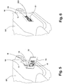
- a casting G1, G2 which is a crankcase for an internal combustion engine, is conventionally formed as a core package having a bottom core 2, a lid core 3, longitudinal side wall cores 4a, 4b and end side wall cores 5, 6.
- the here shown as a unit cores 2-6 can of course in in turn, be known from two or more individual cores.
- feeder, inlets, gates and the like via which a mold cavity 1 enclosed by the mold cavity 7 can be filled with molten metal.
- the molten metal is, for example, a conventional aluminum casting alloy.
- cores 8 and 9 inserts are arranged, which map in well-known manner in the casting G1, G2 cylinder, oil and water channels, etc.
- the bottom core 2 of the mold 1 can be made of a metal material and reusable.
- the other casting cores 3-6, 8 of the casting mold 1 are made of molded material known for this purpose and are destroyed during demoulding of the casting G1, G2.
- the license plate element 11 has two legs 12, 13 which are arranged at right angles to one another and each have a flat outer surface on their side remote from the angle ⁇ enclosed between them.
- the relevant outer surface of the leg 12 forms a casting mold surface 14 associated with the mold cavity 7 and thus with the cast part G1, G2 to be cast respectively, whereas the outer surface of the second leg 13 arranged at right angles thereto forms an information surface 15.
- DMC coded information I1, I2 is shown.
- the representation of the information I1, I2 takes place in each case by impressed into the respective surface, the DMC coding arranged according to dome-like depressions V1, V2 of about 1 mm in diameter.
- the leg 13 of the license plate element 11 Prior to the casting of the casting G1, the leg 13 of the license plate element 11, which has the information surface 15 with the information I2, in a slot-shaped receptacle 16 formed in the surface 10 of the end wall side core 5.
- the seat of the leg 13 in the receptacle 16 is so precise fit that no molten metal enters the receptacle during casting, in particular the information surface 15 in the region of the information I2 arranged there is not wetted with molten metal.
- the leg 13 is pushed so far into the receptacle 16, that the other leg 12 of the license plate element 11 abuts with its side remote from the casting surface 14 surface 17 largely tight against the surface 10 of the end face wall core 5.
- the molten metal flows around the leg 12 of the license plate element 11, so that on the one hand the recesses V1 formed as information I1 the casting surface 14 are filled with molten metal and on the other hand, the molten metal comprises the edges of the leg 12.
- the casting mold 1 can be conveyed in a manner known per se into a heat treatment furnace, in which the decomposition of the casting mold 1 is promoted by supplying heat and at the same time a heat treatment of the casting G1 takes place.
- the casting G1 can also solidify in any other way and then be removed from the mold.
- the license plate member 11 After the solidification and demolding of the casting G1 the license plate member 11 is firmly seated on the surface 18 of the casting G1, which is represented by the surface 10 of the end face wall core 5 on the casting G1.
- An at least positive fit of the license plate element 11 is secured by solidified molten metal M, which has flowed during casting around the edges of the leg 12 while the leg 12 has partially traced behind and so the leg 12 clasps.
- the information I1 supporting leg 13 of molten metal has remained unwetted. Accordingly, the information I1 can now be easily detected by a corresponding reading device, not shown here, and all process data necessary for quality assurance and error tracking can be assigned to the casting G1 on the basis of the information I1 in a database.
- the casting G1 undergoes a mechanical aftertreatment ("cleaning") in which, in a known manner, the residues of the casting mold adhering to it, the molding elements not required for the function of the casting, and seams unavoidable at joints of casting cores and the like be separated from the casting G1.
- the casting G1 is subjected to a final sandblast treatment, in which also the identification element 11 is separated from the casting G1 and exposed the underlying, until then covered by the leg 12 with its adjacent to the casting G1 casting surface 14 surface portion 19 of the casting G1.
- the information I1 previously represented on the casting surface 14 by the depressions V1 embossed there is then permanently imaged in a corresponding pattern of point-like elevations E1.
- the information IG1 thus formed on the casting G1 can be read out again at any time, so that even after a long service life of the casting G1 it can still be determined exactly how the casting G1 has been manufactured and which process parameters have been set.
- a strip-shaped identification element 20 also made of sheet metal material, has been used in the production of the casting G2.
- the one surface of the license plate element 20 serves as a casting surface 21, whereas the one on the opposite side of the license plate element 20th existing surface serves as an information surface 22.
- the information surface 22 and the casting surface 21 are divided into two longitudinal halves L1, L2 with respect to the longitudinal extension L of the license plate element 20.
- the information surface 22 carries in its longitudinal half L1 the information assigned to it I1, whereas the casting surface 21 in its longitudinal half L2 carries its associated information I2.
- the information I1, I2 of information surface 22 and casting surface 21 are thus arranged offset from one another.
- the information I1, I2 are shown as in the license plate element 11 formed by in the respective surface 21,22 depressions V1, V2.
- the license plate member 20 is also disposed on the surface 10 of the end wall side core 5.
- a receptacle 23 whose shape and dimensions are adapted to the license plate member 20 so that the license plate member 20 tightly against the flat base of the receptacle 23 and the edges of the license plate member 20 when pouring slightly from the Flag element 20 incoming melt can be penetrated.
- the solidified casting metal clasps the edges of the license plate element 20, so that this is also held securely and firmly to the casting G2 after demoulding at least by positive locking.
- the present at the now close to the casting G2 adjacent casting surface 21 of the license plate element 20 information I2 is as in the casting G1 in the from the license plate element 20th Covered surface portion 24 of the casting G2 has been stamped, whereas the provided on the now exposed information surface 22 of the license plate element 21 information I1 is exposed and can be detected by a reading device.
- a method is available with which castings G1, G2 permanently provided with readable information IG1, IG2 can be produced.
- a license plate element 11, 20 having at one side an information surface 15, 22 provided with information I 1, I 2 and at another side a cast part G 1, G 2 associated with the casting G 1, G 2, also having information I 1, I 2 a casting mold surface 10 associated with a mold cavity 7 of a casting mold 1, so that the information surface 15, 22 is covered, while the casting surface 14, 21 of the indicator element 11, 20 is exposed in the mold cavity 7.
- a molten metal M is poured into the casting mold 1 while wetting the casting surface 14, so that a material, positive or non-positive connection of the identification element 11, 20 to the casting G 1, G 2 is produced during casting or solidification of the molten metal M and the information I1, I2 present on the casting surface 14, 21 is reproduced on the associated surface 18 of the casting G1, G2 in the manner of a stamp.
- the casting G1, G2 is removed from the mold 1 and cleaned in a conventional manner.
Landscapes
- Engineering & Computer Science (AREA)
- Mechanical Engineering (AREA)
- Molds, Cores, And Manufacturing Methods Thereof (AREA)
- Vehicle Waterproofing, Decoration, And Sanitation Devices (AREA)
- Moulds For Moulding Plastics Or The Like (AREA)
Claims (15)
- Procédé de fabrication d'une pièce moulée (G1, G2) pourvue d'une information lisible (IG1, IG2), comportant les étapes de travail suivantes :a) Mise à disposition d'un élément distinctif (11, 20) qui présente- sur un côté une surface d'informations (15, 22) pourvue d'une information (I1, I2) et- sur un autre côté une surface de pièce moulée (14, 21) associée à la pièce moulée (G1, G2), sur laquelle une information (I1, I2) est également présente ;b) agencement de l'élément distinctif (11, 20) dans un moule (1) qui définit une cavité de moule (7) reproduisant la pièce moulée à mouler (G1, G2), où l'élément distinctif (11, 20) est agencé sur une surface de moule (10) associée à la cavité de moule (7) de telle manière que la surface d'informations (15, 22) est recouverte par rapport à la cavité de moule (7), pendant que la surface de la pièce moulée (14, 21) de l'élément distinctif (11, 20) se trouve dégagée et orientée vers la cavité de moule (7) ;c) faire couler un métal en fusion (M) dans le moule (1) en mouillant la surface de pièce moulée (14, 21) de l'élément distinctif (11, 20) avec un métal en fusion (M) ;d) solidification de la coulée de métal en fusion (M) sur la pièce moulée (G1, G2), où, lors de la coulée ou de la solidification, une liaison de matière, de forme ou de force de l'élément distinctif (11, 20) à la pièce moulée (G1, G2) se forme, et l'information existante (11, 12) sur la surface de la pièce moulée (14, 21) se reproduit, lors de la coulée ou de la solidification de la coulée de métal en fusion (M), à la manière d'un tampon sur la surface associée (18) de la pièce moulée (G1, G2) ;e) démoulage de la pièce moulée (G1, G2) hors du moule (1) ;f) nettoyage de la pièce moulée (G1, G2).
- Procédé selon la revendication 1,
caractérisé en ce que
l'élément distinctif (11, 20) est enlevé lors d'un traitement ultérieur de la pièce moulée (G1, G2). - Procédé selon l'une des revendications précédentes,
caractérisé en ce que
la pièce moulée (G1, G2) subit un traitement thermique. - Procédé selon l'une des revendications précédentes,
caractérisé en ce que
la pièce moulée (G1, G2) subit un traitement mécanique ultérieur lors duquel l'on agit mécaniquement sur la pièce moulée (G1, G2). - Procédé selon l'une des revendications précédentes,
caractérisé en ce que
l'élément distinctif (20) est une bande de tôle. - Procédé selon la revendication 5,
caractérisé en ce que
l'information (I1) est agencée sur la surface d'information (22) opposée à l'information (I2) sur la surface de pièce moulée (21) de l'élément distinctif (20). - Procédé selon la revendication 6,
caractérisé en ce que
les informations (I1, I2) sont agencées décalées les unes par rapport aux autres sur les surfaces d'information (22) et de pièce moulée (21) de l'élément distinctif (20). - Procédé selon l'une des revendications 1 à 4,
caractérisé en ce que
l'élément distinctif (11) est une équerre métallique. - Procédé selon la revendication 8,
caractérisé en ce que
l'élément distinctif (11) présente sur une de ses branches (12) la surface de pièce moulée (14) et sur son autre branche (13) la surface d'information (15). - Procédé selon l'une des revendications précédentes,
caractérisé en ce
qu'au moins une des informations (I1, I2) pourvues sur l'élément distinctif (11, 20) est lisible par machine. - Procédé selon la revendication 10,
caractérisé en ce que
l'information lisible par machine (I1, 12) se compose de données à travers lesquelles l'on peut déterminer le moment ou les paramètres de production par technique de coulée de la pièce moulée (G1, G2). - Procédé selon la revendication 11,
caractérisé en ce que
des données enregistrées dans une base de données sont associées à l'information lisible par machine (IG1, IG2) représentée sur la pièce moulée (G1, G2). - Procédé selon la revendication 12,
caractérisé en ce
qu'avec chaque étape de procédé à laquelle la pièce moulée est soumise (G1, G2), d'autres données lisibles sont associées aux données associées aux informations lisibles par machine (IG1, IG2) représentées sur la pièce moulée (G1, G2) dans la base de données. - Procédé selon l'une des revendications précédentes,
caractérisé en ce que
le moule (1) est formé au moins partiellement par des noyaux (2-6, 8) se composant d'un matériau de moulage. - Procédé selon la revendication 14,
caractérisé en ce que
l'élément distinctif (11, 20) est implanté à fleur d'une surface (10) d'un des noyaux de coulée (2-6, 8).
Applications Claiming Priority (2)
| Application Number | Priority Date | Filing Date | Title |
|---|---|---|---|
| DE102015102308.3A DE102015102308A1 (de) | 2015-02-18 | 2015-02-18 | Verfahren zum Kennzeichnen eines Gussteils |
| PCT/IB2016/000076 WO2016132196A1 (fr) | 2015-02-18 | 2016-02-02 | Procédé de marquage d'une pièce moulée |
Publications (2)
| Publication Number | Publication Date |
|---|---|
| EP3283246A1 EP3283246A1 (fr) | 2018-02-21 |
| EP3283246B1 true EP3283246B1 (fr) | 2019-08-07 |
Family
ID=55358015
Family Applications (1)
| Application Number | Title | Priority Date | Filing Date |
|---|---|---|---|
| EP16704474.2A Active EP3283246B1 (fr) | 2015-02-18 | 2016-02-02 | Procédé de marquage d'une pièce moulée |
Country Status (7)
| Country | Link |
|---|---|
| US (1) | US10052686B2 (fr) |
| EP (1) | EP3283246B1 (fr) |
| JP (1) | JP6419975B2 (fr) |
| KR (1) | KR101930003B1 (fr) |
| CN (1) | CN107249783B (fr) |
| DE (1) | DE102015102308A1 (fr) |
| WO (1) | WO2016132196A1 (fr) |
Families Citing this family (11)
| Publication number | Priority date | Publication date | Assignee | Title |
|---|---|---|---|---|
| DE102018118969A1 (de) * | 2018-08-03 | 2020-02-06 | Zollern Gmbh & Co. Kg | Einzelteilrückverfolgung von Feingussbauteilen und das Bereitstellen von maschinenlesbaren Codes auf Feingussbauteilen |
| DE102019202750B3 (de) * | 2019-02-28 | 2020-03-12 | Fraunhofer-Gesellschaft zur Förderung der angewandten Forschung e.V. | Verfahren zur Kennzeichnung von Metallgussbauteilen mittels elektronischer Transponder |
| FR3094919B1 (fr) * | 2019-04-12 | 2023-04-21 | Renaul S A S | Procédé et outil pour le marquage sur une pièce moulée dans un moule, d’un paramètre lié à l’opération de moulage |
| EP3736064A1 (fr) | 2019-05-10 | 2020-11-11 | Disa Industries A/S | Ligne de production de fonderie et procédé de fonctionnement d'une telle ligne de production de fonderie |
| CN110530411A (zh) * | 2019-07-08 | 2019-12-03 | 金榀精密工业(苏州)有限公司 | 智能来料检测标示系统 |
| CN110508779A (zh) * | 2019-07-08 | 2019-11-29 | 金榀精密工业(苏州)有限公司 | 基于参数转移式的快速标记体系 |
| DE102019007188A1 (de) * | 2019-10-16 | 2021-04-22 | Gienanth Gmbh | Vorrichtung und Verfahren zur Qualitätsverbesserung beim automatisierten maschinellen Gussverfahren mittels Identifizierung der Gussteile durch Mustererkennung und Strukturerkennung |
| DE202019004266U1 (de) | 2019-10-16 | 2019-11-07 | Gienanth Gmbh | Vorrichtung zur Qualitätsverbesserung beim Maschinen-Gussverfahren mittels Identifizierung der Gussteile durch Mustererkennung und Strukturerkennung. |
| US11693652B2 (en) | 2021-04-16 | 2023-07-04 | 27 Software U.S. Inc. | Automated authoring of software solutions from a data model |
| DE102022210130A1 (de) | 2022-09-26 | 2024-03-28 | Volkswagen Aktiengesellschaft | Verfahren und Ausleseeinrichtung zum Auslesen eines Datensatzes aus einem Daten-Matrix-Code |
| FR3163588B1 (fr) * | 2024-06-21 | 2026-07-24 | Fonderie Et Mec Generale Castelbriantaise | dispositif de marquage d’une pièce de fonderie coulée dans un moule en sable |
Family Cites Families (18)
| Publication number | Priority date | Publication date | Assignee | Title |
|---|---|---|---|---|
| JPS5017018B1 (fr) * | 1970-09-10 | 1975-06-18 | ||
| JPS5327576B2 (fr) | 1973-06-20 | 1978-08-09 | ||
| US4900637A (en) * | 1988-10-07 | 1990-02-13 | Aluminum Company Of America | Tag for labeling an article cast from molten material, method therefore and article |
| JPH0475761A (ja) | 1990-03-30 | 1992-03-10 | Toto Ltd | 情報マークを有する鋳物製品 |
| CH687130A5 (de) * | 1992-04-10 | 1996-09-30 | Fischer Georg Giessereianlagen | Verfahren und Vorrichtung zur individuellen Kennzeichnung von Nassguss-Sandformen. |
| US5465780A (en) * | 1993-11-23 | 1995-11-14 | Alliedsignal Inc. | Laser machining of ceramic cores |
| CN1204559A (zh) * | 1997-04-24 | 1999-01-13 | 新东工业株式会社 | 测量铸模强度并在铸模上压制标记的装置 |
| US6220333B1 (en) | 1998-11-06 | 2001-04-24 | Jay S. Cantwell | Bar code stencil and method of use |
| JP2001300690A (ja) | 2000-04-19 | 2001-10-30 | Hitachi Metals Ltd | 車両用軽合金製ホイールおよびその製造方法 |
| US6582197B2 (en) | 2001-02-22 | 2003-06-24 | Simon E. Coulson | Method of investment casting with casting identification |
| JP4075761B2 (ja) * | 2003-10-10 | 2008-04-16 | 日産自動車株式会社 | 内燃機関の吸気装置 |
| DE102005018936A1 (de) * | 2004-10-08 | 2006-04-20 | Fraunhofer-Gesellschaft zur Förderung der angewandten Forschung e.V. | Gussbauteil mit integrierten Funktionselementen und Verfahren zu seiner Herstellung |
| DE102006030365B3 (de) * | 2006-06-27 | 2007-12-06 | Siemens Ag | Verfahren zum Herstellen eines Gussteiles |
| DE102007035144A1 (de) * | 2007-07-25 | 2009-01-29 | Ralf Bux | Vorrichtung und Verfahren zur Individualisierung bzw. Kennung eines Werkstücks |
| DE102008024906B3 (de) | 2008-05-23 | 2010-01-07 | Institut für Automatisierung und Informatik GmbH Zentrum für industrielle Forschung und Entwicklung Wernigerode | Verfahren und Vorrichtung zur Markierung von Gussteilen während des Urformprozesses |
| DE202008018295U1 (de) | 2008-12-03 | 2012-08-06 | Nemak Linz Gmbh | Gusskörper |
| ES2389817T3 (es) * | 2008-12-03 | 2012-11-02 | Nemak Linz Gmbh | Cuerpo de fundición y procedimiento para la fabricación de un cuerpo de fundición |
| US20130220567A1 (en) | 2012-02-29 | 2013-08-29 | GM Global Technology Operations LLC | System and method for integrally serializing a cast part |
-
2015
- 2015-02-18 DE DE102015102308.3A patent/DE102015102308A1/de not_active Withdrawn
-
2016
- 2016-02-02 EP EP16704474.2A patent/EP3283246B1/fr active Active
- 2016-02-02 KR KR1020177023138A patent/KR101930003B1/ko not_active Expired - Fee Related
- 2016-02-02 CN CN201680011093.5A patent/CN107249783B/zh active Active
- 2016-02-02 WO PCT/IB2016/000076 patent/WO2016132196A1/fr not_active Ceased
- 2016-02-02 US US15/551,462 patent/US10052686B2/en active Active
- 2016-02-02 JP JP2017535352A patent/JP6419975B2/ja not_active Expired - Fee Related
Non-Patent Citations (1)
| Title |
|---|
| None * |
Also Published As
| Publication number | Publication date |
|---|---|
| EP3283246A1 (fr) | 2018-02-21 |
| US10052686B2 (en) | 2018-08-21 |
| JP2018507112A (ja) | 2018-03-15 |
| JP6419975B2 (ja) | 2018-11-07 |
| KR101930003B1 (ko) | 2018-12-17 |
| KR20170125329A (ko) | 2017-11-14 |
| CN107249783A (zh) | 2017-10-13 |
| US20180036795A1 (en) | 2018-02-08 |
| WO2016132196A1 (fr) | 2016-08-25 |
| CN107249783B (zh) | 2018-10-19 |
| WO2016132196A8 (fr) | 2017-08-10 |
| DE102015102308A1 (de) | 2016-08-18 |
Similar Documents
| Publication | Publication Date | Title |
|---|---|---|
| DE102015102308A1 (de) | Verfahren zum Kennzeichnen eines Gussteils | |
| EP1398098B1 (fr) | Procédé pour la fabrication d'aubes de turbine avec des canaux de refroidissement | |
| DE10207279A1 (de) | Gießverfahren und Gussteil | |
| DE102007005455A1 (de) | Reifenvulkanisationsform und Verfahren zur Herstellung einer Reifenvulkanisationsform | |
| DE102005047035B3 (de) | Verfahren zur Herstellung eines Kolbens für einen Verbrennungsmotor sowie danach hergestellter Kolben | |
| DE202008018295U1 (de) | Gusskörper | |
| DE102007004050A1 (de) | Vorrichtung und Sandkern zur Herstellung eines Zylinderkurbelgehäuses | |
| EP2196272B1 (fr) | Corps coulé et procédé de fabrication d'un corps coulé | |
| DE2659190C2 (de) | Tragvorrichtung für ein Modell für Präzisionsgießverfahren | |
| DE19925674B4 (de) | Kennzeichnung von Gußteilen | |
| WO2019120804A1 (fr) | Procédé de production d'une partie de moule ainsi qu'insert d'alimentation destiné à être utilisé dans un tel procédé | |
| EP3038770B1 (fr) | Procédé de fabrication de surfaces de codage à partir d'une pièce brute | |
| DE102019202750B3 (de) | Verfahren zur Kennzeichnung von Metallgussbauteilen mittels elektronischer Transponder | |
| DE19807404A1 (de) | Tief- und Streckziehwerkzeug mit durch konturgetreu geformte Masken abgedeckten Funktionsflächen und Verfahren zu seiner Herstellung | |
| DE4443475C2 (de) | Verfahren zur Kennzeichnung von Betonkörpern und Formkasten zur Durchführung dieses Verfahrens | |
| DE3112225C2 (de) | Verfahren zum Herstellen von Formwerkzeugen | |
| AT519404B1 (de) | Verfahren zur Sicherung eines RFID-Chips sowie Stempelplatte | |
| DE888602C (de) | Verfahren zur Herstellung von Dauerformen oder Modelleinrichtungen | |
| DE3733128C1 (en) | Method for keeping core exit surfaces of ceramic hollow bodies provided with sand cores free from core sand | |
| DE102004034802B4 (de) | Metallische Dauerform zur Herstellung von Großgussteilen aus Metalllegierungen | |
| DE69810514T2 (de) | Fliesskanalblock und verfahren zu dessen herstellung | |
| DE2043216C (de) | Vorrichtung zum automatischen Herstellen von Formmasken mit einstückig angeformtem Eingußtrichter | |
| DE3041999A1 (de) | Mehrteilige dauergiessform (kokille) | |
| DE7431729U (de) | Formplatte | |
| DE102018128021A1 (de) | Kokille sowie Verfahren zum Herstellen eines Kurbelgehäuses |
Legal Events
| Date | Code | Title | Description |
|---|---|---|---|
| STAA | Information on the status of an ep patent application or granted ep patent |
Free format text: STATUS: THE INTERNATIONAL PUBLICATION HAS BEEN MADE |
|
| PUAI | Public reference made under article 153(3) epc to a published international application that has entered the european phase |
Free format text: ORIGINAL CODE: 0009012 |
|
| STAA | Information on the status of an ep patent application or granted ep patent |
Free format text: STATUS: REQUEST FOR EXAMINATION WAS MADE |
|
| 17P | Request for examination filed |
Effective date: 20170714 |
|
| AK | Designated contracting states |
Kind code of ref document: A1 Designated state(s): AL AT BE BG CH CY CZ DE DK EE ES FI FR GB GR HR HU IE IS IT LI LT LU LV MC MK MT NL NO PL PT RO RS SE SI SK SM TR |
|
| AX | Request for extension of the european patent |
Extension state: BA ME |
|
| DAV | Request for validation of the european patent (deleted) | ||
| DAX | Request for extension of the european patent (deleted) | ||
| GRAP | Despatch of communication of intention to grant a patent |
Free format text: ORIGINAL CODE: EPIDOSNIGR1 |
|
| STAA | Information on the status of an ep patent application or granted ep patent |
Free format text: STATUS: GRANT OF PATENT IS INTENDED |
|
| INTG | Intention to grant announced |
Effective date: 20180629 |
|
| GRAJ | Information related to disapproval of communication of intention to grant by the applicant or resumption of examination proceedings by the epo deleted |
Free format text: ORIGINAL CODE: EPIDOSDIGR1 |
|
| STAA | Information on the status of an ep patent application or granted ep patent |
Free format text: STATUS: REQUEST FOR EXAMINATION WAS MADE |
|
| GRAS | Grant fee paid |
Free format text: ORIGINAL CODE: EPIDOSNIGR3 |
|
| STAA | Information on the status of an ep patent application or granted ep patent |
Free format text: STATUS: GRANT OF PATENT IS INTENDED |
|
| GRAP | Despatch of communication of intention to grant a patent |
Free format text: ORIGINAL CODE: EPIDOSNIGR1 |
|
| INTC | Intention to grant announced (deleted) | ||
| INTG | Intention to grant announced |
Effective date: 20181206 |
|
| GRAJ | Information related to disapproval of communication of intention to grant by the applicant or resumption of examination proceedings by the epo deleted |
Free format text: ORIGINAL CODE: EPIDOSDIGR1 |
|
| GRAL | Information related to payment of fee for publishing/printing deleted |
Free format text: ORIGINAL CODE: EPIDOSDIGR3 |
|
| STAA | Information on the status of an ep patent application or granted ep patent |
Free format text: STATUS: REQUEST FOR EXAMINATION WAS MADE |
|
| INTC | Intention to grant announced (deleted) | ||
| GRAP | Despatch of communication of intention to grant a patent |
Free format text: ORIGINAL CODE: EPIDOSNIGR1 |
|
| STAA | Information on the status of an ep patent application or granted ep patent |
Free format text: STATUS: GRANT OF PATENT IS INTENDED |
|
| INTG | Intention to grant announced |
Effective date: 20190307 |
|
| GRAA | (expected) grant |
Free format text: ORIGINAL CODE: 0009210 |
|
| STAA | Information on the status of an ep patent application or granted ep patent |
Free format text: STATUS: THE PATENT HAS BEEN GRANTED |
|
| AK | Designated contracting states |
Kind code of ref document: B1 Designated state(s): AL AT BE BG CH CY CZ DE DK EE ES FI FR GB GR HR HU IE IS IT LI LT LU LV MC MK MT NL NO PL PT RO RS SE SI SK SM TR |
|
| REG | Reference to a national code |
Ref country code: GB Ref legal event code: FG4D Free format text: NOT ENGLISH |
|
| REG | Reference to a national code |
Ref country code: CH Ref legal event code: EP Ref country code: AT Ref legal event code: REF Ref document number: 1163061 Country of ref document: AT Kind code of ref document: T Effective date: 20190815 |
|
| REG | Reference to a national code |
Ref country code: DE Ref legal event code: R096 Ref document number: 502016005923 Country of ref document: DE |
|
| REG | Reference to a national code |
Ref country code: IE Ref legal event code: FG4D Free format text: LANGUAGE OF EP DOCUMENT: GERMAN |
|
| REG | Reference to a national code |
Ref country code: NL Ref legal event code: MP Effective date: 20190807 |
|
| REG | Reference to a national code |
Ref country code: LT Ref legal event code: MG4D |
|
| PG25 | Lapsed in a contracting state [announced via postgrant information from national office to epo] |
Ref country code: LT Free format text: LAPSE BECAUSE OF FAILURE TO SUBMIT A TRANSLATION OF THE DESCRIPTION OR TO PAY THE FEE WITHIN THE PRESCRIBED TIME-LIMIT Effective date: 20190807 Ref country code: HR Free format text: LAPSE BECAUSE OF FAILURE TO SUBMIT A TRANSLATION OF THE DESCRIPTION OR TO PAY THE FEE WITHIN THE PRESCRIBED TIME-LIMIT Effective date: 20190807 Ref country code: PT Free format text: LAPSE BECAUSE OF FAILURE TO SUBMIT A TRANSLATION OF THE DESCRIPTION OR TO PAY THE FEE WITHIN THE PRESCRIBED TIME-LIMIT Effective date: 20191209 Ref country code: NO Free format text: LAPSE BECAUSE OF FAILURE TO SUBMIT A TRANSLATION OF THE DESCRIPTION OR TO PAY THE FEE WITHIN THE PRESCRIBED TIME-LIMIT Effective date: 20191107 Ref country code: BG Free format text: LAPSE BECAUSE OF FAILURE TO SUBMIT A TRANSLATION OF THE DESCRIPTION OR TO PAY THE FEE WITHIN THE PRESCRIBED TIME-LIMIT Effective date: 20191107 Ref country code: SE Free format text: LAPSE BECAUSE OF FAILURE TO SUBMIT A TRANSLATION OF THE DESCRIPTION OR TO PAY THE FEE WITHIN THE PRESCRIBED TIME-LIMIT Effective date: 20190807 Ref country code: NL Free format text: LAPSE BECAUSE OF FAILURE TO SUBMIT A TRANSLATION OF THE DESCRIPTION OR TO PAY THE FEE WITHIN THE PRESCRIBED TIME-LIMIT Effective date: 20190807 Ref country code: FI Free format text: LAPSE BECAUSE OF FAILURE TO SUBMIT A TRANSLATION OF THE DESCRIPTION OR TO PAY THE FEE WITHIN THE PRESCRIBED TIME-LIMIT Effective date: 20190807 |
|
| PG25 | Lapsed in a contracting state [announced via postgrant information from national office to epo] |
Ref country code: GR Free format text: LAPSE BECAUSE OF FAILURE TO SUBMIT A TRANSLATION OF THE DESCRIPTION OR TO PAY THE FEE WITHIN THE PRESCRIBED TIME-LIMIT Effective date: 20191108 Ref country code: ES Free format text: LAPSE BECAUSE OF FAILURE TO SUBMIT A TRANSLATION OF THE DESCRIPTION OR TO PAY THE FEE WITHIN THE PRESCRIBED TIME-LIMIT Effective date: 20190807 Ref country code: IS Free format text: LAPSE BECAUSE OF FAILURE TO SUBMIT A TRANSLATION OF THE DESCRIPTION OR TO PAY THE FEE WITHIN THE PRESCRIBED TIME-LIMIT Effective date: 20191207 Ref country code: RS Free format text: LAPSE BECAUSE OF FAILURE TO SUBMIT A TRANSLATION OF THE DESCRIPTION OR TO PAY THE FEE WITHIN THE PRESCRIBED TIME-LIMIT Effective date: 20190807 Ref country code: AL Free format text: LAPSE BECAUSE OF FAILURE TO SUBMIT A TRANSLATION OF THE DESCRIPTION OR TO PAY THE FEE WITHIN THE PRESCRIBED TIME-LIMIT Effective date: 20190807 Ref country code: LV Free format text: LAPSE BECAUSE OF FAILURE TO SUBMIT A TRANSLATION OF THE DESCRIPTION OR TO PAY THE FEE WITHIN THE PRESCRIBED TIME-LIMIT Effective date: 20190807 |
|
| PG25 | Lapsed in a contracting state [announced via postgrant information from national office to epo] |
Ref country code: TR Free format text: LAPSE BECAUSE OF FAILURE TO SUBMIT A TRANSLATION OF THE DESCRIPTION OR TO PAY THE FEE WITHIN THE PRESCRIBED TIME-LIMIT Effective date: 20190807 |
|
| PG25 | Lapsed in a contracting state [announced via postgrant information from national office to epo] |
Ref country code: DK Free format text: LAPSE BECAUSE OF FAILURE TO SUBMIT A TRANSLATION OF THE DESCRIPTION OR TO PAY THE FEE WITHIN THE PRESCRIBED TIME-LIMIT Effective date: 20190807 Ref country code: RO Free format text: LAPSE BECAUSE OF FAILURE TO SUBMIT A TRANSLATION OF THE DESCRIPTION OR TO PAY THE FEE WITHIN THE PRESCRIBED TIME-LIMIT Effective date: 20190807 Ref country code: IT Free format text: LAPSE BECAUSE OF FAILURE TO SUBMIT A TRANSLATION OF THE DESCRIPTION OR TO PAY THE FEE WITHIN THE PRESCRIBED TIME-LIMIT Effective date: 20190807 Ref country code: EE Free format text: LAPSE BECAUSE OF FAILURE TO SUBMIT A TRANSLATION OF THE DESCRIPTION OR TO PAY THE FEE WITHIN THE PRESCRIBED TIME-LIMIT Effective date: 20190807 Ref country code: PL Free format text: LAPSE BECAUSE OF FAILURE TO SUBMIT A TRANSLATION OF THE DESCRIPTION OR TO PAY THE FEE WITHIN THE PRESCRIBED TIME-LIMIT Effective date: 20190807 |
|
| PG25 | Lapsed in a contracting state [announced via postgrant information from national office to epo] |
Ref country code: SK Free format text: LAPSE BECAUSE OF FAILURE TO SUBMIT A TRANSLATION OF THE DESCRIPTION OR TO PAY THE FEE WITHIN THE PRESCRIBED TIME-LIMIT Effective date: 20190807 Ref country code: IS Free format text: LAPSE BECAUSE OF FAILURE TO SUBMIT A TRANSLATION OF THE DESCRIPTION OR TO PAY THE FEE WITHIN THE PRESCRIBED TIME-LIMIT Effective date: 20200224 Ref country code: SM Free format text: LAPSE BECAUSE OF FAILURE TO SUBMIT A TRANSLATION OF THE DESCRIPTION OR TO PAY THE FEE WITHIN THE PRESCRIBED TIME-LIMIT Effective date: 20190807 Ref country code: CZ Free format text: LAPSE BECAUSE OF FAILURE TO SUBMIT A TRANSLATION OF THE DESCRIPTION OR TO PAY THE FEE WITHIN THE PRESCRIBED TIME-LIMIT Effective date: 20190807 |
|
| REG | Reference to a national code |
Ref country code: DE Ref legal event code: R097 Ref document number: 502016005923 Country of ref document: DE |
|
| PLBE | No opposition filed within time limit |
Free format text: ORIGINAL CODE: 0009261 |
|
| STAA | Information on the status of an ep patent application or granted ep patent |
Free format text: STATUS: NO OPPOSITION FILED WITHIN TIME LIMIT |
|
| PG2D | Information on lapse in contracting state deleted |
Ref country code: IS |
|
| 26N | No opposition filed |
Effective date: 20200603 |
|
| PG25 | Lapsed in a contracting state [announced via postgrant information from national office to epo] |
Ref country code: SI Free format text: LAPSE BECAUSE OF FAILURE TO SUBMIT A TRANSLATION OF THE DESCRIPTION OR TO PAY THE FEE WITHIN THE PRESCRIBED TIME-LIMIT Effective date: 20190807 |
|
| REG | Reference to a national code |
Ref country code: CH Ref legal event code: PL |
|
| GBPC | Gb: european patent ceased through non-payment of renewal fee |
Effective date: 20200202 |
|
| REG | Reference to a national code |
Ref country code: BE Ref legal event code: MM Effective date: 20200229 |
|
| PG25 | Lapsed in a contracting state [announced via postgrant information from national office to epo] |
Ref country code: LU Free format text: LAPSE BECAUSE OF NON-PAYMENT OF DUE FEES Effective date: 20200202 Ref country code: MC Free format text: LAPSE BECAUSE OF FAILURE TO SUBMIT A TRANSLATION OF THE DESCRIPTION OR TO PAY THE FEE WITHIN THE PRESCRIBED TIME-LIMIT Effective date: 20190807 |
|
| PG25 | Lapsed in a contracting state [announced via postgrant information from national office to epo] |
Ref country code: LI Free format text: LAPSE BECAUSE OF NON-PAYMENT OF DUE FEES Effective date: 20200229 Ref country code: CH Free format text: LAPSE BECAUSE OF NON-PAYMENT OF DUE FEES Effective date: 20200229 |
|
| PG25 | Lapsed in a contracting state [announced via postgrant information from national office to epo] |
Ref country code: IE Free format text: LAPSE BECAUSE OF NON-PAYMENT OF DUE FEES Effective date: 20200202 Ref country code: GB Free format text: LAPSE BECAUSE OF NON-PAYMENT OF DUE FEES Effective date: 20200202 Ref country code: FR Free format text: LAPSE BECAUSE OF NON-PAYMENT OF DUE FEES Effective date: 20200229 |
|
| PG25 | Lapsed in a contracting state [announced via postgrant information from national office to epo] |
Ref country code: BE Free format text: LAPSE BECAUSE OF NON-PAYMENT OF DUE FEES Effective date: 20200229 |
|
| REG | Reference to a national code |
Ref country code: AT Ref legal event code: MM01 Ref document number: 1163061 Country of ref document: AT Kind code of ref document: T Effective date: 20210202 |
|
| PG25 | Lapsed in a contracting state [announced via postgrant information from national office to epo] |
Ref country code: AT Free format text: LAPSE BECAUSE OF NON-PAYMENT OF DUE FEES Effective date: 20210202 |
|
| PG25 | Lapsed in a contracting state [announced via postgrant information from national office to epo] |
Ref country code: MT Free format text: LAPSE BECAUSE OF FAILURE TO SUBMIT A TRANSLATION OF THE DESCRIPTION OR TO PAY THE FEE WITHIN THE PRESCRIBED TIME-LIMIT Effective date: 20190807 Ref country code: CY Free format text: LAPSE BECAUSE OF FAILURE TO SUBMIT A TRANSLATION OF THE DESCRIPTION OR TO PAY THE FEE WITHIN THE PRESCRIBED TIME-LIMIT Effective date: 20190807 |
|
| PG25 | Lapsed in a contracting state [announced via postgrant information from national office to epo] |
Ref country code: MK Free format text: LAPSE BECAUSE OF FAILURE TO SUBMIT A TRANSLATION OF THE DESCRIPTION OR TO PAY THE FEE WITHIN THE PRESCRIBED TIME-LIMIT Effective date: 20190807 |
|
| PGFP | Annual fee paid to national office [announced via postgrant information from national office to epo] |
Ref country code: DE Payment date: 20260217 Year of fee payment: 11 |