EP3283721B1 - Motorisierte antriebsvorrichtung für eine schliess- oder sonnenschutz-heimautomatisierungsanlage, zugehörige heimautomatisierungsanlage und verfahren zur steuerung des betriebs solch einer vorrichtung - Google Patents
Motorisierte antriebsvorrichtung für eine schliess- oder sonnenschutz-heimautomatisierungsanlage, zugehörige heimautomatisierungsanlage und verfahren zur steuerung des betriebs solch einer vorrichtung Download PDFInfo
- Publication number
- EP3283721B1 EP3283721B1 EP16716230.4A EP16716230A EP3283721B1 EP 3283721 B1 EP3283721 B1 EP 3283721B1 EP 16716230 A EP16716230 A EP 16716230A EP 3283721 B1 EP3283721 B1 EP 3283721B1
- Authority
- EP
- European Patent Office
- Prior art keywords
- electromechanical actuator
- power supply
- photovoltaic cell
- control unit
- drive device
- Prior art date
- Legal status (The legal status is an assumption and is not a legal conclusion. Google has not performed a legal analysis and makes no representation as to the accuracy of the status listed.)
- Active
Links
Images


Classifications
-
- E—FIXED CONSTRUCTIONS
- E06—DOORS, WINDOWS, SHUTTERS, OR ROLLER BLINDS IN GENERAL; LADDERS
- E06B—FIXED OR MOVABLE CLOSURES FOR OPENINGS IN BUILDINGS, VEHICLES, FENCES OR LIKE ENCLOSURES IN GENERAL, e.g. DOORS, WINDOWS, BLINDS, GATES
- E06B9/00—Screening or protective devices for wall or similar openings, with or without operating or securing mechanisms; Closures of similar construction
- E06B9/56—Operating, guiding or securing devices or arrangements for roll-type closures; Spring drums; Tape drums; Counterweighting arrangements therefor
- E06B9/68—Operating devices or mechanisms, e.g. with electric drive
- E06B9/72—Operating devices or mechanisms, e.g. with electric drive comprising an electric motor positioned inside the roller
-
- E—FIXED CONSTRUCTIONS
- E06—DOORS, WINDOWS, SHUTTERS, OR ROLLER BLINDS IN GENERAL; LADDERS
- E06B—FIXED OR MOVABLE CLOSURES FOR OPENINGS IN BUILDINGS, VEHICLES, FENCES OR LIKE ENCLOSURES IN GENERAL, e.g. DOORS, WINDOWS, BLINDS, GATES
- E06B9/00—Screening or protective devices for wall or similar openings, with or without operating or securing mechanisms; Closures of similar construction
- E06B9/24—Screens or other constructions affording protection against light, especially against sunshine; Similar screens for privacy or appearance; Slat blinds
- E06B2009/2476—Solar cells
-
- E—FIXED CONSTRUCTIONS
- E06—DOORS, WINDOWS, SHUTTERS, OR ROLLER BLINDS IN GENERAL; LADDERS
- E06B—FIXED OR MOVABLE CLOSURES FOR OPENINGS IN BUILDINGS, VEHICLES, FENCES OR LIKE ENCLOSURES IN GENERAL, e.g. DOORS, WINDOWS, BLINDS, GATES
- E06B9/00—Screening or protective devices for wall or similar openings, with or without operating or securing mechanisms; Closures of similar construction
- E06B9/56—Operating, guiding or securing devices or arrangements for roll-type closures; Spring drums; Tape drums; Counterweighting arrangements therefor
- E06B9/68—Operating devices or mechanisms, e.g. with electric drive
- E06B2009/6809—Control
-
- G—PHYSICS
- G08—SIGNALLING
- G08C—TRANSMISSION SYSTEMS FOR MEASURED VALUES, CONTROL OR SIMILAR SIGNALS
- G08C17/00—Arrangements for transmitting signals characterised by the use of a wireless electrical link
- G08C17/02—Arrangements for transmitting signals characterised by the use of a wireless electrical link using a radio link
Definitions
- the present invention relates to a motorized drive device for a home automation system for closing or sun protection.
- the present invention also relates to a home automation closure or sun protection system comprising a roll-up screen, by means of such a motorized driving device, on a winding tube rotated by an electromechanical actuator, and a method operating control of such a motorized drive device.
- the present invention relates to the field of occultation devices comprising a motorized drive device moving a screen between at least a first position and a second position.
- a motorized driving device comprises an electromechanical actuator of a movable closure, concealment or sun protection element such as a shutter, a door, a grating, a blind or any other equivalent equipment, hereafter called a screen .
- the autonomous electric power supply device comprises a battery and a photovoltaic cell.
- the electromechanical actuator is electrically connected to the autonomous electric power supply device.
- the electronic control unit comprises a wireless control command receiving module.
- the electronic control unit is configured to detect information transmitted via an electrical power supply line connecting the photovoltaic cell to the electromechanical actuator by means of a switch positioned on the power supply line as well as by means of elements for detecting variations in the voltage on the power supply line.
- this motorized drive device has the disadvantage of adding a switch positioned on the power supply line connecting the photovoltaic cell to the electromechanical actuator to inhibit the operation of the control command receiving module without wire, so as to limit the consumption of electrical energy by the electronic control unit and to avoid the discharge of the battery, between the moment of assembly of the motorized drive device at the factory and the time of commissioning of the motorized drive device in the home automation system for closing or sun protection.
- the object of the present invention is to solve the aforementioned drawbacks and to propose a motorized drive device for a home automation system for closing or sun protection, a home automation system for closing or associated sun protection, as well as a control method in which operation of such a device to reduce the consumption of electrical energy by an electronic control unit and to avoid the discharge of at least one battery, between the time of assembly of the motor drive device in the factory and the time of commissioning of the motorized drive device in the home automation system for closing or sun protection, as well as when using the motorized drive device put into service in the home automation system for closing or sunscreen.
- the measuring elements of a quantity related to the electrical power supply of the electromechanical actuator by said at least one photovoltaic cell make it possible to detect periods of power supply and power supply interruption of the power supply.
- electromechanical actuator from said at least one photovoltaic cell so as to use said at least one photovoltaic cell, and in particular the supply of electrical energy delivered by it to the electromechanical actuator, to awaken the electronic unit of control or place the electronic control unit in a standby mode.
- the inputs and outputs of the electronic control unit are scanned at a predetermined periodicity lower than that used when the measuring elements detect the power supply of the control unit.
- the electronic control unit enters a standby mode, so as to reduce the consumption of electrical energy by the electronic control unit and to avoid the discharge of said at least one battery.
- the motorized driving device is suitable for to be ordered.
- the electronic control unit can be reset, at least partially, by executing a sequence of periods of power supply and power failure of the electromechanical actuator, where the periods of power and cut electrical power supply of the electromechanical actuator are determined through measuring elements measuring a quantity related to the supply of electrical energy of the electromechanical actuator by said at least one photovoltaic cell.
- At least part of the data stored by the electronic control unit is reset, following the detection by the measuring elements of a sequence of periods respectively corresponding to the presence or absence of the connecting electrical connection. said at least one photovoltaic cell to the electromechanical actuator.
- the electronic control unit comprises a wireless command command receiving module.
- the present invention aims, according to a second aspect, a home automation closure or sun protection system comprising a screen rollable by means of a motorized drive device according to the invention on a winding tube rotated by an actuator electromechanical.
- This home automation system has characteristics and advantages similar to those described above in connection with the motorized drive device according to the invention.
- This control method has characteristics and advantages similar to those described above in connection with the motorized drive device according to the invention.
- the sequence of periods of power supply and power failure of the electromechanical actuator is simulated by the connection and disconnection of a first electrical connector connected to the at least one photovoltaic cell. cooperating with a second electrical connector connected to the electronic control unit.
- the sequence of periods of power supply and power failure of the electromechanical actuator is simulated by means of an external electrical power source, where the power source external electrical energy is electrically connected to the electromechanical actuator to replace said at least one photovoltaic cell.
- the sequence of periods of power supply and power failure of the electromechanical actuator is simulated by removing a cover element from said at least one photovoltaic cell and positioning the covering said at least one photovoltaic cell.
- the electronic control unit comprises a wireless control command receiving module
- this module is inhibited, following the detection by the electronic control unit of the power supply power failure of the control unit. electromechanical actuator from said at least one photovoltaic cell.
- the wireless command command receiving module is woken up according to a predetermined periodicity, so as to detect control commands transmitted to the electronic control unit.
- the predetermined periodicity of awakening of the wireless control command receiving module is dependent on the luminous power determined by means of the measuring elements measuring a quantity related to the electrical power supply of the electromechanical actuator by said at least one photovoltaic cell.
- the predetermined wakeup periodicity of the wireless control command receiving module is dependent on the charge level of said at least one battery.
- a home automation system according to the invention and installed in a building having an opening 1, window or door, equipped with a screen 2 belonging to a concealment device 3, in particular a motorized roller shutter.
- the concealment device 3 may be a rolling shutter, a fabric blind or with adjustable blades, or a rolling gate.
- the present invention applies to all types of occulting device.
- the screen 2 of the occulting device 3 is wound on a winding tube 4 driven by a motorized drive device 5 and movable between a wound position, particularly high, and a unwound position, particularly low.
- the movable screen 2 of the concealment device 3 is a closure, concealment and / or sun protection screen, winding on the winding tube 4, the inner diameter is substantially equivalent to the outer diameter of an electromechanical actuator 11, so that the electromechanical actuator 11 can be inserted into the winding tube 4, during assembly of the occulting device 3.
- the motorized drive device 5 comprises the electromechanical actuator 11, in particular of the tubular type, making it possible to rotate the winding tube 4, so as to unroll or wind up the screen 2 of the occulting device 3.
- the concealment device 3 comprises the winding tube 4 for winding the screen 2, where, in the mounted state, the electromechanical actuator 11 is inserted into the winding tube 4.
- the shutter which forms the concealment device 3
- the shutter comprises an apron comprising horizontal blades articulated to each other, forming the screen 2 of the shutter 3, and guided by two lateral rails 6. These blades are joined when the deck 2 of the shutter 3 reaches its low position unrolled.
- the wound up position corresponds to the support of a final L-shaped end plate 8 of the deck 2 of the shutter 3 against an edge of a box 9 of the shutter 3
- the lowered low position corresponds to the support of the final end blade 8 of the deck 2 of the shutter 3 against a threshold 7 of the opening 1.
- the first blade of the shutter 3, opposite to the end plate, is connected to the winding tube 4 by means of at least one hinge 10.
- the winding tube 4 is disposed inside the trunk 9 of the roller shutter 3.
- the apron 2 of the roller shutter 3 winds and unwinds around the winding tube 4 and is housed at least in part at the inside the trunk 9.
- the box 9 is disposed above the opening 1, or in the upper part of the opening 1.
- the motor drive device 5 is controlled by a control unit.
- the control unit may be, for example, a local control unit 12, where the local control unit 12 may be wired or wirelessly connected to a central control unit 13.
- the central control unit 13 controls the local control unit 12, as well as other similar local control units distributed throughout the building.
- the central control unit 13 may be in communication with a remote weather station outside the building, including, in particular, one or more sensors that can be configured to determine, for example, a temperature, a brightness, or a speed Wind.
- a remote control 14 which may be a type of local control unit, and provided with a control keyboard, which comprises means of selection and display, further allows a user to intervene on the actuator electromechanical 11 and / or the central control unit 13.
- the motorized drive device 5 is preferably configured to execute the unwinding or winding commands of the screen 2 of the concealment device 3, which can be transmitted, in particular, by the remote control unit 14.
- the electromechanical actuator 11 comprises an electric motor 16.
- the electric motor 16 comprises a rotor and a stator, not shown and positioned coaxially around an axis of rotation X, which is also the axis of rotation of the tube. winding 4 in mounted configuration of the motorized drive device 5.
- Control means of the electromechanical actuator 11 according to the invention, allowing the displacement of the screen 2 of the concealment device 3, are constituted by at least one electronic control unit 15.
- This electronic control unit 15 is adapted to operate the electric motor 16 of the electromechanical actuator 11, and, in particular, to allow the electric power supply of the electric motor 16.
- the electronic control unit 15 controls, in particular, the electric motor 16, so as to open or close the screen 2, as described above.
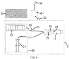
- the electronic control unit 15 also comprises a control command receiving module 27, as illustrated in FIG. figure 4 , the control commands being issued by a command transmitter, such as the remote control 14 intended to control the electromechanical actuator 11.
- control command reception module 27 of the electronic control unit 15 is of wireless type.
- control command receiving module 27 is configured to receive radio control commands.
- the command order receiving module 27 may also allow the reception of control commands transmitted by wire means.
- the control means of the electromechanical actuator 11 comprise hardware and / or software means.
- the hardware means may comprise at least one microcontroller.
- the electromechanical actuator 11 is supplied with electrical energy by means of at least one battery 24, which can be recharged by at least one photovoltaic cell 25, as illustrated in FIG. figure 4 .
- the electromechanical actuator 11 makes it possible to move the screen 2 of the occulting device 3.
- the electromechanical actuator 11 comprises a power supply cable 18 allowing its supply of electrical energy from the battery or batteries 24.
- a housing 17 of the electromechanical actuator 11 is preferably of cylindrical shape.
- the housing 17 is made of a metallic material.
- the housing material of the electromechanical actuator is not limiting and may be different and, in particular, plastic.
- the electromechanical actuator 11 also comprises a gear reduction device 19 and an output shaft 20.
- the electromechanical actuator 11 may also include a limit and / or obstacle detection device, which may be mechanical or electronic.
- the electric motor 16 and the gear reduction device 19 are disposed inside the casing 17 of the electromechanical actuator 11.
- the output shaft 20 of the electromechanical actuator 11 is disposed inside the winding tube 4, and at least partly outside the casing 17 of the electromechanical actuator 11.
- the output shaft 20 of the electromechanical actuator 11 is coupled by connecting means 22 to the winding tube 4, in particular a wheel-shaped connection means.
- the electromechanical actuator 11 also comprises a shutter element 21 at one end of the casing 17.
- the casing 17 of the electromechanical actuator 11 is fixed to a support 23, in particular a cheek, of the trunk 9 of the concealment device 3 by means of the closure element 21 forming a torque support, in particular a shutter head and torque recovery.
- the closure element 21 is also called a fixed point of the electromechanical actuator 11.
- the electronic control unit 15 is arranged, in other words integrated, inside the housing 17 of the electromechanical actuator 11.
- the electronic control unit 15 is disposed outside the housing 17 of the electromechanical actuator 11 and, in particular, mounted on the support 23 or in the closure element 21.
- the motorized drive device 5 comprises an autonomous electric power supply device 26.
- the electromechanical actuator 11 is electrically connected to the autonomous electric power supply device 26.
- the autonomous electric power supply device 26 comprises the battery or batteries 24 and the photovoltaic cell or cells 25.
- each battery 24 is disposed inside the trunk 9 of the concealment device 3.
- the expression “the battery 24” is used to designate one or more batteries according to the configuration of the autonomous electric power supply device 26.
- the expression “the photovoltaic cell 25” is used to designate one or more photovoltaic cells according to the configuration of the autonomous electric power supply device 26.
- the photovoltaic cell 25 is electrically connected directly to the electronic control unit 15.
- the battery 24 is electrically connected directly to the electronic control unit 15.
- the photovoltaic cell 25 is electrically connected to the battery 24.
- the battery 24 is electrically connected to the electronic control unit 15.
- the battery 24 is rechargeable type and supplies electrical energy to the electromechanical actuator 11. And the battery 24 is supplied with electrical energy by the photovoltaic cell 25.
- the recharging of the battery 24 is implemented by solar energy by means of the photovoltaic cell 25.
- the battery 24 can be recharged without having to dismount part of the trunk 9 of the concealment device 3.
- the motorized drive device 5 and, in particular, the photovoltaic cell 25 comprises loading elements configured to charge the battery 24 from the solar energy recovered by the photovoltaic cell 25.
- the charging elements configured to charge the battery 24 from solar energy convert the solar energy recovered by the photovoltaic cell 25 into electrical energy.
- the autonomous electric power supply device 26 comprises a plurality of photovoltaic cells 25 constituting a photovoltaic panel.
- the electric power supply of the electromechanical actuator 11 by the battery 24 can be substituted for an electrical power supply of the electromechanical actuator 11 by an electrical power supply network.
- the supply of electrical energy of the electromechanical actuator 11 by the battery 24 eliminates a connection to the power supply network.
- the electrical power supply of the electromechanical actuator 11 is implemented, on the one hand, by an electrical energy supply network and, on the other hand, by the battery 24.
- the supply of electrical energy of the electromechanical actuator 11 by the battery 24 makes it possible, in particular, to provide for a power supply cut-off of the electromechanical actuator 11 by an electrical power supply network.
- the electromechanical actuator 11 is supplied with electrical energy, on the one hand, by means of a power supply cable connected to the electrical energy supply network and, on the other hand, by the battery 24. .
- the supply of electrical energy to the electromechanical actuator 11 via an electrical energy supply network makes it possible to recharge the battery 24, in particular when the battery 24 is insufficiently recharged by the photovoltaic cell 25.
- the electronic control unit 15 is configured to detect periods of power supply and power supply interruption of the electromechanical actuator 11 from the photovoltaic cell 25, only by means of measuring elements 28. a quantity related to the supply of electrical energy of the electromechanical actuator 11 by this photovoltaic cell 25.
- a power supply period of the electromechanical actuator 11 from the photovoltaic cell 25 corresponds to the presence of the electrical connection connecting the photovoltaic cell 25 to the electromechanical actuator 11.
- a power supply cut-off period of the electromechanical actuator 11 from the photovoltaic cell 25 corresponds to the absence of the electrical connection connecting the photovoltaic cell 25 to the electromechanical actuator 11.
- the absence of the connecting electrical connection the photovoltaic cell 25 with the electromechanical actuator 11 may be due to the withdrawal of the photovoltaic cell 25 with respect to the autonomous electric power supply device 26, at the interruption of the electrical connection between the photovoltaic cell 25 and the electromechanical actuator 11, or the loss of electrical connection between the photovoltaic cell 25 and the electromechanical actuator 11.
- the measuring elements 28 of a magnitude related to the electrical power supply of the electromechanical actuator 11 by the photovoltaic cell 25 make it possible to detect periods of power supply and power supply interruption of the power supply.
- the measuring elements 28 of a magnitude related to the electrical power supply of the electromechanical actuator 11 by the photovoltaic cell 25 detect the power supply cutoff of the electromechanical actuator 11 from of the photovoltaic cell 25, the inputs and outputs of the electronic control unit 15, in particular of a microcontroller, are scanned at a predetermined periodicity lower than that used when the measuring elements 28 detect the supply of electrical energy of the electromechanical actuator 11 from the photovoltaic cell 25, or even not scanned, so as to reduce the consumption of electrical energy by the electronic control unit 15 and to avoid the discharge of the battery 24.
- the electronic control unit 15 enters a standby mode, so as to reduce the consumption of electrical energy by the electronic control unit 15 and to avoid the discharge of the battery 24.
- Detection of the power supply cut-off of the electromechanical actuator 11 from the photovoltaic cell 25 by the measuring elements 28 makes it possible to diagnose a fault related to the power supply of the electromechanical actuator 11 by the photovoltaic cell 25 and, in particular, to signal this defect by a visual and / or audible signal.
- the motor drive device 5 is controllable.
- the periods of power supply and power failure of the electromechanical actuator 11 are detected by means of a direct electrical connection between the measuring elements 28 and the photovoltaic cell 25 and, in particular, without the quantity measured by the measuring elements 28 passes through other elements constituting the autonomous electric power supply device 26, such as, for example, the battery 24.
- the detection of supply or of the power supply cut-off of the electromechanical actuator 11 from the photovoltaic cell 25 is implemented by measuring, through the measuring elements 28, a quantity related to the supply of electrical energy delivered by the photovoltaic cell 25.
- the magnitude related to the supply of electrical energy delivered by the photovoltaic cell 25 may be, in particular, a voltage, a current or an impedance.
- the value of the quantity related to the supply of electrical energy of the electromechanical actuator 11 by the photovoltaic cell 25 is proportional to the light power sensed by the photovoltaic cell 25, in other words, the value of this quantity supplying electrical energy l
- the electromechanical actuator 11 is dependent on the light intensity of the solar energy sensed by the photovoltaic cell 25.
- the measuring elements 28 form an integral part of the electronic control unit 15.
- the measuring elements 28 may comprise either a voltage divider, a comparator and a microcontroller, one of whose inputs is provided with an analog-digital converter, in the case where the measured quantity is a voltage, a shunt resistor and a microcontroller, one of whose inputs is provided with an analog-digital converter, in the case where the measured quantity is a current.
- the electronic control unit 15 is also configured to reset to the least part of the data stored by the electronic control unit 15, following the simulation of a sequence of power supply periods and power supply power failure of the electromechanical actuator 11, where the power periods and power supply failure are detected through the measuring elements 28.
- the electronic control unit 15 can be reset, at least partially, by executing a sequence of periods of power supply and power failure of the electromechanical actuator 11, where the periods of power and power supply power failure of the electromechanical actuator 11 are determined through the measuring elements 28 measuring a quantity related to the supply of electrical energy of the electromechanical actuator 11 by the photovoltaic cell 25.
- the data memorized by the electronic control unit 15 that can be reset can be the end-of-travel positions of the screen 2, the obstacle detection threshold or thresholds, or the paired control units 12, 13, 14. with the electromechanical actuator 11.
- the sequence of periods of power supply and power failure of the electromechanical actuator 11 is simulated by the connection and disconnection of a first electrical connector 29 connected to the photovoltaic cell 25 cooperating with a second electrical connector 30 connected to the electronic control unit 15.
- a power supply period of the electromechanical actuator 11 by the photovoltaic cell 25 is implemented by the electrical connection of the first electrical connector 29 connected to the at least one photovoltaic cell 25 with the second connected electrical connector 30. to the electronic control unit 15.
- a period of power supply power failure of the electromechanical actuator 11 from the photovoltaic cell 25 is implemented by the electrical disconnection of the first electrical connector 29 connected to the at least one photovoltaic cell 25 with respect to the second electrical connector 30 connected to the electronic control unit 15.
- the measuring elements 28 measure a quantity related to the supply of electrical energy delivered by the photovoltaic cell 25.
- the value of the measured quantity is greater than a threshold value, this means that the photovoltaic cell 25 captures light rays.
- the first electrical connector 29 connected to the at least one photovoltaic cell 25 is disconnected from the second electrical connector 30 connected to the electronic control unit 15, the value of the measured quantity is zero and therefore less than a threshold value, it means that the photovoltaic cell 25 does not pick up light rays.
- the first electrical connector 29 is connected to the photovoltaic cell 25 by means of a power supply cable.
- the second electrical connector 30 is connected to the electronic control unit 15 by means of a power supply cable.
- the first and second electrical connectors 29, 30 respectively connected to said at least one photovoltaic cell 25 and to the electronic control unit 15 are accessible, in particular by dismounting a part of the box 9 of the device. occultation 3.
- the sequence of periods of power supply and power supply power failure of the electromechanical actuator 11 is simulated by means of an external electrical power supply source 31.
- the source of external electric power supply 31 is electrically connected to the electromechanical actuator 11 in replacement of the photovoltaic cell 25.
- a power supply period of the electromechanical actuator 11 by the external electric power supply source 31 is implemented either by the electrical connection of the second electrical connector 30 connected to the electronic control unit 15 with a third electrical connector 32 connected to the external electrical power supply source 31, or by closing a switch of the external electric power supply source 31.
- a period of power supply power failure of the electromechanical actuator 11 from the external electric power supply source 31 is implemented either by the electrical disconnection of the second electrical connector 30 connected to the electronic control unit 15 with respect to the third electrical connector 32 connected to the external electric power supply source 31, or by opening the interrupte of the external electric power supply 31.
- the measuring elements 28 measure a quantity related to the supply of electrical energy delivered by the external electric power supply source 31.
- the second electrical connector 30 connected to the electronic control unit 15 is connected on the third electrical connector 32 connected to the external electric power supply source 31, or when the switch of the external electric power supply source 31 is closed, the value of the measured quantity is greater than a threshold value .
- the second electrical connector 30 connected to the electronic control unit 15 is disconnected from the third electrical connector 32 connected to the external electrical power supply source 31, or when the switch of the external electrical power supply source 31 is open, the value of the measured quantity is zero and therefore less than a threshold value.
- the first electrical connector 29 is connected to the at least one photovoltaic cell 25 by means of a power supply cable.
- the second electrical connector 30 is connected to the electronic control unit 15 by means of a power supply cable.
- the third electrical connector 32 is connected to the external electric power source 31 by means of a power supply cable.
- the simulation of the sequence of periods of power supply and power failure of the electromechanical actuator 11 by means of the external electric power supply source 31 is implemented when the photovoltaic cell 25 is faulty or when the photovoltaic cell 25 is not installed in the motorized drive device 5, in particular during an after-sales service intervention or during the assembly of the motorized drive device 5.
- the first, second and third electrical connectors 29, 30, 32 respectively connected to said at least one photovoltaic cell 25, to the electronic control unit 15 and to the external electric power supply source. 31 are accessible, in particular by removing a portion of the trunk 9 of the occulting device 3.
- the external electric power supply source 31 may be a transformer electrically connected to the power supply network, so as to transform an alternating voltage into a DC voltage.
- the AC voltage of the mains or mains voltage has, for example, a value of 230 VRMS (peak value of 325V) for the French power grid.
- the mains voltage may have values different, depending on the power grid of the country where the home automation system is located.
- the DC supply voltage of the electromechanical actuator 11, obtained at the output of the transformer may be, for example, 12 V.
- a power supply period of the electromechanical actuator 11 by the external electric power supply source 31 is implemented by the electrical connection of an electrical outlet 34 connected to the power supply source.
- a power supply power failure period of the electromechanical actuator 11 from the external electric power supply source 31 is implemented by the electrical disconnection of the electrical outlet 34 connected at the source of external electric power supply 31 with respect to the power supply connected to the power supply network.
- the electrical outlet 34 is connected to the external electric power supply source 31 by means of a power supply cable.
- the sequence of periods of power supply and power failure of the electromechanical actuator 11 is simulated by removing a cover member 33 from the photovoltaic cell 25 and positioning the covering 33 on the photovoltaic cell 25.
- a power supply period of the electromechanical actuator 11 by the photovoltaic cell 25 is implemented by the removal of the covering element 33 placed on the photovoltaic cell 25.
- a period of power failure the electrical energy of the electromechanical actuator 11 from the photovoltaic cell 25 is implemented by the positioning of the covering element 33 on the photovoltaic cell 25.
- the measuring elements 28 measure a quantity related to the supply of electrical energy delivered by the photovoltaic cell 25.
- the value of the measured quantity is greater than a threshold value, it means that the photovoltaic cell 25 captures light rays.
- the covering element 33 is placed on the photovoltaic cell 25, the value of the measured quantity is below a threshold value, this means that the photovoltaic cell 25 does not pick up or not enough light rays.
- the first and second electrical connectors 29, 30 respectively connected to said at least one photovoltaic cell 25 and to the electronic control unit 15 may not be accessible.
- the first, second and third electrical connectors 29, 30, 32 respectively connected to the at least one photovoltaic cell 25, to the electronic control unit 15 and to the power supply source external 31 are arranged at the level of the support 23 and, in particular, inside the trunk 9 of the concealment device 3, following the assembly of the motorized drive device 5 in the concealment device 3.
- the electronic control unit 15 comprises the wireless control command reception module 27.
- the wireless command command receiving module 27 is inhibited, following detection by the electronic control unit 15 of the power supply cut-off of the electromechanical actuator 11 from the cell photovoltaic 25.
- the electronic control unit 15 enters a so-called deep sleep mode so as to inhibit the wireless control command reception module 27.
- the passage into a so-called deep sleep mode following the detection of the power supply power failure of the electromechanical actuator 11 from the photovoltaic cell 25 by the measuring elements 28 reduces the consumption of electrical energy by the electronic control unit 15 and to avoid the discharge of the battery 24.
- the wireless command command receiving module 27 is woken up according to a predetermined periodicity, so as to detect issued command commands, in particular by a command command transmitter which can be for example the remote control 14, to destination of the electronic control unit 15.
- a command command transmitter which can be for example the remote control 14, to destination of the electronic control unit 15.
- the waking up of the wireless control command receiving module 27 according to a predetermined periodicity is preferably implemented in a so-called active standby mode of the electronic control unit 15, so as to temporarily inhibit the module receiving wireless command orders 27.
- the so-called active standby mode of the electronic control unit 15 is implemented, preferably, when the measuring elements 28 of a magnitude related to the electrical power supply of the electromechanical actuator 11 by the photovoltaic cell 25 detect the supply of electrical energy of the electromechanical actuator 11 from the photovoltaic cell 25, and when the wireless command control receiving module 27 has received no order to order, following the flow of a predetermined period of time.
- the predetermined wake-up period of the wireless control command receiving module 27 is dependent on the light output determined by means of the measuring elements 28 measuring a magnitude related to the power supply. of the electromechanical actuator 11 by the photovoltaic cell 25.
- the adaptation of the wake-up period of the wireless control command receiving module 27 as a function of the light power determined by means of the measuring elements 28 makes it possible to reduce the electrical energy consumption by the electronic control unit 15 and to limit the discharge of the battery 24.
- the wake-up period of the wireless control command receiving module 27 is lengthened during the night and reduced during the day, so as to reduce the power consumption by the electronic control unit 15 at the same time. during the night and to ensure reactive operation of the motorized drive device 5 during the day.
- the predetermined wakeup periodicity of the wireless control command receiving module 27 can take a plurality of defined values as a function of threshold values of light power.
- the wakeup periodicity of the wireless control command receiving module 27 may be of the order of 150 milliseconds when the light power determined by means of the measuring elements 28 is less than 10 W / m 2 , of 70 milliseconds when the luminous power determined by means of the measuring elements 28 is between 10 W / m 2 and 200 W / m 2 , and 20 milliseconds when the light power determined by means of the measuring elements 28 is greater than 200 W / m 2 .
- the predetermined wake up period of the wireless control command receiving module 27 is dependent on the level of charge of the battery 24.
- the adaptation of the wake-up period of the wireless command command receiving module 27 as a function of the charge level of the battery 24 makes it possible to reduce the consumption of electrical energy by the electronic control unit 15 and to avoid the discharge of the battery 24.
- reaction time of the motorized drive device 5 following the transmission of a control command, in particular from the remote control 14, allows the user to deduce the battery charge level. 24, since the wake-up period of the wireless control command reception module 27 is longer or shorter, depending on the charge level of the battery 24.
- the predetermined wake-up period of the wireless control command receiving module 27 is dependent, on the one hand, on the light power determined by means of the measuring elements 28 measuring a linked magnitude. to the supply of electrical energy of the electromechanical actuator 11 by the photovoltaic cell 25 and, on the other hand, of the charge level of the battery 24.
- the wakeup periodicity of the wireless control command receiving module 27 may be of the order of 150 milliseconds when the light power determined by means of the measuring elements 28 is less than 10 W / m 2 and that the charge level of the battery 24 is greater than or equal to 50%, of 300 milliseconds when the light power determined by means of the measuring elements 28 is less than 10 W / m 2 and the level charge of the battery 24 is less than 50%.
- the control method comprises a step of detecting periods of supply and power supply interruption of the electromechanical actuator 11 from the photovoltaic cell 25.
- This detection step is carried out only by means of the measuring elements 28 of a magnitude related to the supply of electrical energy to the electromechanical actuator 11 by said at least one photovoltaic cell 25.
- the electronic control unit 15 Following the detection of a power supply period of the electromechanical actuator 11 from the photovoltaic cell 25, the electronic control unit 15 enters a sleep mode, called active, in which the inputs and outputs of the electronic control unit 15, in particular a microcontroller, are scanned at a predetermined periodicity. And, in particular, the wireless command command receiving module 27 is woken up according to a predetermined periodicity, so as to receive a command command issued by a command command transmitter, which can be for example the remote control 14.
- a command command transmitter which can be for example the remote control 14.
- the electronic control unit 15 enters a sleep mode, called deep, during of which the inputs and outputs of the electronic control unit 15, in particular of a microcontroller, are scanned at a predetermined periodicity which is lower than that of the so-called active standby mode implemented following the detection of a period supplying electrical energy to the electromechanical actuator 11 from the photovoltaic cell 25.
- the wireless command command receiving module 27 is inhibited, so as to reduce the electrical power consumption by the electronic control unit 15 and to avoid the discharge of the battery 24.
- the predetermined periodicity of scanning of the inputs and outputs of the electronic control unit 15, in particular of a microcontroller, and, in particular, of the waking up of the wireless control command receiving module 27 is reduced, when the measuring elements 28 measure a zero value or a value lower than a threshold value of the quantity related to the electrical energy supply of the electromechanical actuator 11 by the photovoltaic cell 25.
- the control method also comprises a step of simulating a sequence of periods of power supply and power supply cut-off of the electromechanical actuator 11, where the periods of power supply and power supply cutoff are detected through the measuring elements 28.
- This simulation step can be implemented by the connection and disconnection of the first electrical connector 29 connected to the at least one photovoltaic cell 25 cooperating with the second electrical connector 30 connected to the electronic control unit 15, by means of the external electric power supply source 31 electrically connected to the electromechanical actuator 11 instead of the photovoltaic cell 25, or by the positioning or removal of the covering element 33 on the photovoltaic cell 25.
- the control method comprises a step of resetting at least a portion of the data stored by the electronic control unit 15, following the execution of the simulation step.
- the sequence of feeding and power supply cut-off of the electromechanical actuator 11 comprises a first power supply interruption period for a predetermined period of time, which can be of the order of two seconds, a power supply period during a predetermined period of time, which may be of the order of seven seconds, and a second period of power supply interruption for a predetermined period of time, which may be of the order of two seconds.
- At least part of the data stored by the electronic control unit 15 can be reset, in particular as soon as the predetermined period of time of the second power failure period electrical energy has passed.
- the measuring elements of a quantity related to the electrical power supply of the electromechanical actuator by the photovoltaic cell make it possible to detect periods of power supply and power supply interruption of the electromechanical actuator.
- electromechanical actuator from the photovoltaic cell so as to use the photovoltaic cell, and in particular the supply of electrical energy delivered by it to the electromechanical actuator, to wake up the electronic control unit or to place the electronic control unit in a standby mode.
- the present invention also makes it possible to reinitialize, at least partially, the data stored by the electronic control unit by executing a sequence of periods of power supply and power supply interruption of the electromechanical actuator, where the periods of power supply and power supply power failure of the electromechanical actuator are determined through the measuring elements measuring a quantity related to the supply of electrical energy of the electromechanical actuator by the photovoltaic cell.
- the battery may be a unitary battery or a group of batteries connected by means of an electrical insulator.
Landscapes
- Engineering & Computer Science (AREA)
- Structural Engineering (AREA)
- Architecture (AREA)
- Civil Engineering (AREA)
- Charge And Discharge Circuits For Batteries Or The Like (AREA)
- Control Of Electrical Variables (AREA)
Claims (11)
- Motorisierte Antriebsvorrichtung (5) für eine häusliche Verschließ- oder Sonnenschutzanlage, umfassend:- eine elektromechanische Stellvorrichtung (11),- eine elektronische Steuereinheit (15),- eine Vorrichtung (26) zur autonomen Versorgung mit elektrischer Energie, die mindestens eine Batterie (24) und mindestens eine Photovoltaikzelle (25) umfasst,dadurch gekennzeichnet, dass die elektronische Steuereinheit (15) ausgebildet ist:
∘ wobei die elektromechanische Stellvorrichtung (11) elektrisch mit der Vorrichtung (26) zur autonomen Versorgung mit elektrischer Energie verbunden ist,- Perioden der Versorgung mit elektrischer Energie und der Unterbrechung der Versorgung der elektromechanischen Stellvorrichtung (11) aus der mindestens einen Photovoltaikzelle (25) nur mittels Messelementen (28) einer Größe zu detektieren, die an die Versorgung mit elektrischer Energie der elektromechanischen Stellvorrichtung (11) von der mindestens eine Photovoltaikzelle (25) gebunden ist, und- mindestens einen Teil der von der elektronischen Steuereinheit (15) gespeicherten Daten folgend auf die Simulation einer Sequenz der Perioden der Versorgung mit elektrischer Energie und der Unterbrechung der Versorgung der elektromechanischen Stellvorrichtung (11) neu zu setzen, wobei die Perioden der Versorgung mit elektrischer Energie und der Unterbrechung der Versorgung über die Messelemente (28) detektiert werden. - Motorisierte Antriebsvorrichtung (5) nach Anspruch 1, dadurch gekennzeichnet, dass die elektronische Steuereinheit (15) ein drahtloses Modul (27) zum Empfang von Steuerbefehlen umfasst.
- Häusliche Verschließ- oder Sonnenschutzanlage, umfassend einen mittels einer motorisierten Antriebsvorrichtung (5) auf ein Wickelrohr (4) aufwickelbaren Schirm (2), das zur Drehung von einer elektromechanischen Stellvorrichtung (11) angetrieben wird, dadurch gekennzeichnet, dass die motorisierte Antriebsvorrichtung (5) nach Anspruch 1 oder Anspruch 2 ausgebildet ist.
- Verfahren zur Betriebssteuerung einer motorisierten Antriebsvorrichtung (5) für eine häusliche Verschließ- oder Sonnenschutzanlage, wobei die motorisierte Antriebsvorrichtung (5) umfasst:- eine elektromechanische Stellvorrichtung (11),- eine elektronische Steuereinheit (15),- eine Vorrichtung (26) zur autonomen Versorgung mit elektrischer Energie, die mindestens eine Batterie (24) und mindestens eine Photovoltaikzelle (25) umfasst,dadurch gekennzeichnet, dass das Verfahren mindestens die folgenden Schritte umfasst:
∘ wobei die elektromechanische Stellvorrichtung (11) elektrisch mit der Vorrichtung (26) zur autonomen Versorgung mit elektrischer Energie verbunden ist,- Detektieren von Perioden der Versorgung mit elektrischer Energie und der Unterbrechung der Versorgung der elektromechanischen Stellvorrichtung (11) aus der mindestens einen Photovoltaikzelle (25) nur mittels Messelementen (28) einer Größe, die an die Versorgung mit elektrischer Energie der elektromechanischen Stellvorrichtung (11) von der mindestens eine Photovoltaikzelle (25) gebunden ist,- Simulieren einer Sequenz von Perioden der Versorgung mit elektrischer Energie und der Unterbrechung der Versorgung der elektromechanischen Stellvorrichtung (11), wobei die Perioden der Versorgung mit elektrischer Energie und der Unterbrechung der Versorgung über Messelemente (28) detektiert werden, und- Reinitialisieren mindestens eines Teils der von der elektronischen Steuereinheit (15) gespeicherten Daten folgend auf die Ausführung des Schrittes der Simulation. - Verfahren zur Betriebssteuerung einer motorisierten Antriebsvorrichtung (5) nach Anspruch 4, dadurch gekennzeichnet, dass die Sequenz der Perioden der Versorgung mit elektrischer Energie und der Unterbrechung der Versorgung der elektromechanischen Stellvorrichtung (11) durch das Verbinden und das Abschalten eines ersten elektrischen Schalters (29), der mit der mindestens einen Photovoltaikzelle (25) verbunden ist und mit einem zweiten elektrischen Schalter (30) zusammenarbeitet, der mit der elektronischen Steuereinheit (15) verbunden ist, simuliert wird.
- Verfahren zur Betriebssteuerung einer motorisierten Antriebsvorrichtung (5) nach Anspruch 4, dadurch gekennzeichnet, dass die Sequenz der Perioden der Versorgung mit elektrischer Energie und der Unterbrechung der Versorgung der elektromechanischen Stellvorrichtung (11) mittels einer externen Versorgungsquelle (31) mit elektrischer Energie simuliert wird, wobei die externe Versorgungsquelle (31) mit elektrischer Energie elektrisch mit der elektromechanischen Stellvorrichtung (11) verbunden wird, wobei die mindestens eine Photovoltaikzelle (25) ersetzt wird.
- Verfahren zur Betriebssteuerung einer motorisierten Antriebsvorrichtung (5) nach Anspruch 4, dadurch gekennzeichnet, dass die Sequenz der Perioden der Versorgung mit elektrischer Energie und der Unterbrechung der Versorgung der elektromechanischen Stellvorrichtung (11) simuliert wird, indem ein Element zur Überdeckung (33) der mindestens einen Photovoltaikzelle (25) zurückgezogen wird und indem das Element der Überdeckung (33) über die mindestens eine Photovoltaikzelle (25) positioniert wird.
- Verfahren zur Betriebssteuerung einer motorisierten Antriebsvorrichtung (5) nach einem beliebigen der Ansprüche 4 bis 7, das mit einer motorisierten Antriebsvorrichtung (5) nach Anspruch 2 durchgeführt wird, dadurch gekennzeichnet, dass das drahtlose Modul (27) zum Empfang von Steuerbefehlen folgend auf das Detektieren der Unterbrechung der Versorgung mit elektrischer Energie der elektromechanischen Stellvorrichtung (11) von der mindestens einen Photovoltaikzelle (25) gesperrt wird.
- Verfahren zur Betriebssteuerung einer motorisierten Antriebsvorrichtung (5) nach einem beliebigen der Ansprüche 4 bis 8, das mit einer motorisierten Antriebsvorrichtung (5) nach Anspruch 2 durchgeführt wird, dadurch gekennzeichnet, dass das drahtlose Modul (27) des Empfangs von Steuerbefehlen gemäß einer vorbestimmten Periodizität aufgeweckt wird, um Steuerbefehle, die zu der elektronischen Steuereinheit (15) gesendet werden, zu detektieren.
- Verfahren zur Betriebssteuerung einer motorisierten Antriebsvorrichtung (5) nach Anspruch 9, dadurch gekennzeichnet, dass die vorbestimmte Periodizität des Aufweckens drahtlosen des Moduls (27) zum Empfang von Steuerbefehlen abhängig von der Lichtleistung ist, die über Messelemente (28) bestimmt wird, die eine an die Versorgung mit elektrischer Energie der elektromechanischen Stellvorrichtung (11) durch die mindestens eine Photovoltaikzelle (25) gebundene Größe misst.
- Verfahren zur Betriebssteuerung einer motorisierten Antriebsvorrichtung (5) nach Anspruch 9 oder Anspruch 10, dadurch gekennzeichnet, dass die vorbestimmte Periodizität zum Aufwecken des Moduls (27) des Empfang von Steuerbefehlen abhängig ist von dem Ladezustand der mindestens einen Batterie (24).
Priority Applications (1)
| Application Number | Priority Date | Filing Date | Title |
|---|---|---|---|
| PL16716230T PL3283721T3 (pl) | 2015-04-15 | 2016-04-14 | Urządzenie o napędzie silnikowym dla instalacji automatyki domowej do zamykania lub ochrony przeciwsłonecznej, powiązana instalacja automatyki domowej i sposób sterowania działaniem takiego urządzenia |
Applications Claiming Priority (2)
| Application Number | Priority Date | Filing Date | Title |
|---|---|---|---|
| FR1553317A FR3035144B1 (fr) | 2015-04-15 | 2015-04-15 | Dispositif d'entrainement motorise pour une installation domotique de fermeture ou de protection solaire, installation domotique associee et procede de commande en fonctionnement d'un tel dispositif |
| PCT/EP2016/058213 WO2016166206A1 (fr) | 2015-04-15 | 2016-04-14 | Dispositif d'entraînement motorisé pour une installation domotique de fermeture ou de protection solaire, installation domotique associée et procédé de commande en fonctionnement d'un tel dispositif |
Publications (2)
| Publication Number | Publication Date |
|---|---|
| EP3283721A1 EP3283721A1 (de) | 2018-02-21 |
| EP3283721B1 true EP3283721B1 (de) | 2019-05-01 |
Family
ID=53366151
Family Applications (1)
| Application Number | Title | Priority Date | Filing Date |
|---|---|---|---|
| EP16716230.4A Active EP3283721B1 (de) | 2015-04-15 | 2016-04-14 | Motorisierte antriebsvorrichtung für eine schliess- oder sonnenschutz-heimautomatisierungsanlage, zugehörige heimautomatisierungsanlage und verfahren zur steuerung des betriebs solch einer vorrichtung |
Country Status (7)
| Country | Link |
|---|---|
| US (1) | US10017987B2 (de) |
| EP (1) | EP3283721B1 (de) |
| AU (1) | AU2016247401B2 (de) |
| DK (1) | DK3283721T3 (de) |
| FR (1) | FR3035144B1 (de) |
| PL (1) | PL3283721T3 (de) |
| WO (1) | WO2016166206A1 (de) |
Cited By (2)
| Publication number | Priority date | Publication date | Assignee | Title |
|---|---|---|---|---|
| EP4407134A1 (de) * | 2023-01-30 | 2024-07-31 | VKR Holding A/S | Gebäudeöffnungsabdeckungssystem mit einem antriebssystem mit einer aufweckeinheit zur bereitstellung eines aufweckbefehls und verfahren zum bereitstellen einer automatischen ersten aktivierung einer funkkommunikationssteueranordnung eines antriebssystems |
| WO2025141104A1 (fr) * | 2023-12-31 | 2025-07-03 | Somfy Activites Sa | Procédé de fonctionnement d'un actionneur électromécanique d'une installation de fermeture, d'occultation ou de protection solaire |
Families Citing this family (8)
| Publication number | Priority date | Publication date | Assignee | Title |
|---|---|---|---|---|
| DE102015111072A1 (de) * | 2015-07-08 | 2017-01-12 | Fraba B.V. | Wartungs- und Überwachungssystem zur Überwachung eines Tororgans |
| FR3040421B1 (fr) * | 2015-08-28 | 2017-10-06 | Somfy Sas | Installation domotique de fermeture ou de protection solaire et procede de recharge d'une batterie pour une telle installation |
| AU2017423232B2 (en) * | 2017-07-10 | 2021-07-29 | Berker Gmbh & Co. Kg | Electrical unit and associated additional functional module |
| US11393645B2 (en) * | 2017-07-10 | 2022-07-19 | Berker Gmbh & Co. Kg | Electrical equipment and additional functional module associated therewith |
| FR3072118B1 (fr) * | 2017-10-10 | 2019-11-08 | Somfy Activites Sa | Actionneur electromecanique tubulaire et installation domotique comprenant un tel actionneur |
| JP7705749B2 (ja) * | 2021-07-09 | 2025-07-10 | 株式会社Lixil | 電動開閉体装置 |
| JP7659488B2 (ja) * | 2021-11-29 | 2025-04-09 | 文化シヤッター株式会社 | 開閉体装置 |
| CN116446777B (zh) * | 2023-04-28 | 2024-08-30 | 东莞市歌声美实业有限公司 | 自动及手动双模式卷帘门 |
Family Cites Families (8)
| Publication number | Priority date | Publication date | Assignee | Title |
|---|---|---|---|---|
| US5760558A (en) * | 1995-07-24 | 1998-06-02 | Popat; Pradeep P. | Solar-powered, wireless, retrofittable, automatic controller for venetian blinds and similar window converings |
| US5793174A (en) * | 1996-09-06 | 1998-08-11 | Hunter Douglas Inc. | Electrically powered window covering assembly |
| FR2874229B1 (fr) * | 2004-08-10 | 2006-11-24 | Somfy Sas | Procede de fonctionnement d'un volet roulant commande et alimente par le biais d'une interface de commande filaire |
| EP1710389B1 (de) * | 2005-04-05 | 2016-11-09 | BUBENDORFF Société Anonyme | Motorantriebsvorrichtung, insbesondere für eine motorisierten Verschlusseinrichtung |
| FR2910523B1 (fr) | 2006-12-26 | 2009-02-27 | Simu Soc Par Actions Simplifie | Ensemble autonome d'actionnement de volet roulant ou store |
| US8165719B2 (en) * | 2009-06-25 | 2012-04-24 | Kinney Laurence F | System and method for an electrical insulating shutter system |
| FR2959884B1 (fr) * | 2010-05-06 | 2012-06-01 | Bubendorff | Procede de controle de l'alimentation en energie electrique d'une batterie d'un dispositif d'occultation par un panneau photovoltaique et dispositif d'occultation comportant un systeme pour un tel controle |
| US8723466B2 (en) * | 2010-09-17 | 2014-05-13 | Lutron Electronics Co., Inc. | Motorized venetian blind system |
-
2015
- 2015-04-15 FR FR1553317A patent/FR3035144B1/fr not_active Expired - Fee Related
-
2016
- 2016-04-14 WO PCT/EP2016/058213 patent/WO2016166206A1/fr not_active Ceased
- 2016-04-14 EP EP16716230.4A patent/EP3283721B1/de active Active
- 2016-04-14 PL PL16716230T patent/PL3283721T3/pl unknown
- 2016-04-14 AU AU2016247401A patent/AU2016247401B2/en active Active
- 2016-04-14 US US15/565,919 patent/US10017987B2/en active Active
- 2016-04-14 DK DK16716230.4T patent/DK3283721T3/da active
Non-Patent Citations (1)
| Title |
|---|
| None * |
Cited By (4)
| Publication number | Priority date | Publication date | Assignee | Title |
|---|---|---|---|---|
| EP4407134A1 (de) * | 2023-01-30 | 2024-07-31 | VKR Holding A/S | Gebäudeöffnungsabdeckungssystem mit einem antriebssystem mit einer aufweckeinheit zur bereitstellung eines aufweckbefehls und verfahren zum bereitstellen einer automatischen ersten aktivierung einer funkkommunikationssteueranordnung eines antriebssystems |
| WO2024160561A1 (en) * | 2023-01-30 | 2024-08-08 | Vkr Holding A/S | A drive system comprising a wake-up unit configured to provide a wake-up command |
| WO2025141104A1 (fr) * | 2023-12-31 | 2025-07-03 | Somfy Activites Sa | Procédé de fonctionnement d'un actionneur électromécanique d'une installation de fermeture, d'occultation ou de protection solaire |
| FR3157885A1 (fr) * | 2023-12-31 | 2025-07-04 | Somfy Activites Sa | Procédé de fonctionnement d’un actionneur électromécanique d’une installation de fermeture, d’occultation ou de protection solaire. |
Also Published As
| Publication number | Publication date |
|---|---|
| DK3283721T3 (da) | 2019-05-20 |
| FR3035144A1 (fr) | 2016-10-21 |
| US10017987B2 (en) | 2018-07-10 |
| AU2016247401A1 (en) | 2017-10-26 |
| AU2016247401B2 (en) | 2018-03-01 |
| EP3283721A1 (de) | 2018-02-21 |
| FR3035144B1 (fr) | 2017-05-05 |
| WO2016166206A1 (fr) | 2016-10-20 |
| PL3283721T3 (pl) | 2019-11-29 |
| US20180106104A1 (en) | 2018-04-19 |
Similar Documents
| Publication | Publication Date | Title |
|---|---|---|
| EP3283721B1 (de) | Motorisierte antriebsvorrichtung für eine schliess- oder sonnenschutz-heimautomatisierungsanlage, zugehörige heimautomatisierungsanlage und verfahren zur steuerung des betriebs solch einer vorrichtung | |
| EP3109394B1 (de) | Betriebssteuerungsverfahren einer motorisierten antriebsvorrichtung einer hausanlage | |
| EP3504393B1 (de) | Motorisierte antriebsvorrichtung für eine schliess- oder sonnenschutzeinheit und entsprechende einheit | |
| EP3803021B1 (de) | Rollladenvorrichtung für eine heimautomatisierungs- oder sonnenschutzvorrichtung in einem gebäude und zugehörige heimautomatisierungsinstallation | |
| EP3341550A1 (de) | Heimautomationsanlage zum verschliessen oder zum sonnenschutz und verfahren zum aufladen einer batterie für solch eine anlage | |
| EP4232680B1 (de) | Verfahren zur steuerung des betriebs einer beschattungsvorrichtung und zugehörige beschattungsvorrichtung | |
| EP3433446B1 (de) | Verfahren zur konfigurierung und steuerung des betriebs einer motorisierten antriebsvorrichtung für eine heimautomatisierungseinheit sowie zugehörige einheit und motorisierte antriebsvorrichtung | |
| EP4172452B1 (de) | Beschattungsvorrichtung mit einer motorischen antriebseinrichtung | |
| EP3528310B1 (de) | Speichervorrichtung für elektrische energie, entsprechende motorisierte antriebsvorrichtung und entsprechende haustechnikanlage | |
| WO2025103699A1 (fr) | Procédé de commande d'un dispositif d'occultation et dispositif d'occultation associé | |
| EP3292262A1 (de) | Verfahren zur konfigurierung und steuerung des betriebs einer motorisierten antriebsvorrichtung für eine heimautomatisierungseinheit sowie zugehörige einheit und motorisierte antriebsvorrichtung | |
| FR3088362A1 (fr) | Procede de commande en fonctionnement d'une installation domotique de fermeture, d'occultation ou de protection solaire et installation domotique associee | |
| EP3588772A1 (de) | Autonome stromzuführungsvorrichtung, entsprechende motorisierte antriebsvorrichtung und entsprechende haustechnikanlage | |
| FR3093124A1 (fr) | Agencement de moyens de stockage d'energie electrique dans une motorisation de volet roulant et le volet roulant l'incluant | |
| EP2937505B1 (de) | Heimanlage, die eine befestigungsvorrichtung für einen motorisierten antriebsmechanismus eines aufrollrohrs eines bildschirms in einem kasten umfasst | |
| EP3376633B1 (de) | Motorvorrichtung | |
| FR3128731A1 (fr) | Dispositif d’entraînement motorisé, dispositif d’occultation et procédé de commande associés | |
| EP4175119B1 (de) | Motorisierte antriebsvorrichtung, verdunkelungsvorrichtung und steuerungsverfahren dafür | |
| EP4576463A1 (de) | Stromversorgungsvorrichtung, motorisierte antriebsvorrichtung mit solch einer stromversorgungsvorrichtung und verdunkelungsvorrichtung dafür | |
| EP4657713A1 (de) | Elektromechanischer aktuator für eine verdunkelungsvorrichtung | |
| EP4648255A1 (de) | Verfahren zur steuerung eines elektromechanischen aktuators für eine verdunkelungsvorrichtung und elektromechanischer aktuator dafür | |
| EP4530432A1 (de) | Verfahren zur betriebssteuerung einer motorischen antriebsvorrichtung, motorisierte antriebsvorrichtung und verdunkelungsvorrichtung dafür | |
| EP3910780A1 (de) | Stromversorgungsvorrichtung, elektromechanisches stellglied, das eine solche stromversorgungsvorrichtung umfasst, und schliess- , verdunkelungs- oder sonnenschutzanlage, die ein solches elektromechanisches stellglied umfasst | |
| FR3139592A1 (fr) | Dispositif d’entraînement motorisé d’un dispositif d’occultation et dispositif d’occultation associé |
Legal Events
| Date | Code | Title | Description |
|---|---|---|---|
| STAA | Information on the status of an ep patent application or granted ep patent |
Free format text: STATUS: THE INTERNATIONAL PUBLICATION HAS BEEN MADE |
|
| PUAI | Public reference made under article 153(3) epc to a published international application that has entered the european phase |
Free format text: ORIGINAL CODE: 0009012 |
|
| STAA | Information on the status of an ep patent application or granted ep patent |
Free format text: STATUS: REQUEST FOR EXAMINATION WAS MADE |
|
| 17P | Request for examination filed |
Effective date: 20171011 |
|
| AK | Designated contracting states |
Kind code of ref document: A1 Designated state(s): AL AT BE BG CH CY CZ DE DK EE ES FI FR GB GR HR HU IE IS IT LI LT LU LV MC MK MT NL NO PL PT RO RS SE SI SK SM TR |
|
| AX | Request for extension of the european patent |
Extension state: BA ME |
|
| DAV | Request for validation of the european patent (deleted) | ||
| DAX | Request for extension of the european patent (deleted) | ||
| REG | Reference to a national code |
Ref country code: DE Ref legal event code: R079 Ref document number: 602016013223 Country of ref document: DE Free format text: PREVIOUS MAIN CLASS: E06B0009680000 Ipc: E06B0009720000 |
|
| GRAP | Despatch of communication of intention to grant a patent |
Free format text: ORIGINAL CODE: EPIDOSNIGR1 |
|
| STAA | Information on the status of an ep patent application or granted ep patent |
Free format text: STATUS: GRANT OF PATENT IS INTENDED |
|
| RIC1 | Information provided on ipc code assigned before grant |
Ipc: E06B 9/68 20060101ALI20181113BHEP Ipc: E06B 9/24 20060101ALI20181113BHEP Ipc: G08C 17/02 20060101ALI20181113BHEP Ipc: E06B 9/72 20060101AFI20181113BHEP |
|
| INTG | Intention to grant announced |
Effective date: 20181128 |
|
| GRAS | Grant fee paid |
Free format text: ORIGINAL CODE: EPIDOSNIGR3 |
|
| GRAA | (expected) grant |
Free format text: ORIGINAL CODE: 0009210 |
|
| STAA | Information on the status of an ep patent application or granted ep patent |
Free format text: STATUS: THE PATENT HAS BEEN GRANTED |
|
| AK | Designated contracting states |
Kind code of ref document: B1 Designated state(s): AL AT BE BG CH CY CZ DE DK EE ES FI FR GB GR HR HU IE IS IT LI LT LU LV MC MK MT NL NO PL PT RO RS SE SI SK SM TR |
|
| REG | Reference to a national code |
Ref country code: GB Ref legal event code: FG4D Free format text: NOT ENGLISH |
|
| REG | Reference to a national code |
Ref country code: CH Ref legal event code: EP Ref country code: AT Ref legal event code: REF Ref document number: 1127113 Country of ref document: AT Kind code of ref document: T Effective date: 20190515 |
|
| REG | Reference to a national code |
Ref country code: DK Ref legal event code: T3 Effective date: 20190516 |
|
| REG | Reference to a national code |
Ref country code: DE Ref legal event code: R096 Ref document number: 602016013223 Country of ref document: DE |
|
| REG | Reference to a national code |
Ref country code: IE Ref legal event code: FG4D Free format text: LANGUAGE OF EP DOCUMENT: FRENCH |
|
| REG | Reference to a national code |
Ref country code: NL Ref legal event code: MP Effective date: 20190501 |
|
| REG | Reference to a national code |
Ref country code: LT Ref legal event code: MG4D |
|
| PG25 | Lapsed in a contracting state [announced via postgrant information from national office to epo] |
Ref country code: SE Free format text: LAPSE BECAUSE OF FAILURE TO SUBMIT A TRANSLATION OF THE DESCRIPTION OR TO PAY THE FEE WITHIN THE PRESCRIBED TIME-LIMIT Effective date: 20190501 Ref country code: NL Free format text: LAPSE BECAUSE OF FAILURE TO SUBMIT A TRANSLATION OF THE DESCRIPTION OR TO PAY THE FEE WITHIN THE PRESCRIBED TIME-LIMIT Effective date: 20190501 Ref country code: PT Free format text: LAPSE BECAUSE OF FAILURE TO SUBMIT A TRANSLATION OF THE DESCRIPTION OR TO PAY THE FEE WITHIN THE PRESCRIBED TIME-LIMIT Effective date: 20190901 Ref country code: HR Free format text: LAPSE BECAUSE OF FAILURE TO SUBMIT A TRANSLATION OF THE DESCRIPTION OR TO PAY THE FEE WITHIN THE PRESCRIBED TIME-LIMIT Effective date: 20190501 Ref country code: LT Free format text: LAPSE BECAUSE OF FAILURE TO SUBMIT A TRANSLATION OF THE DESCRIPTION OR TO PAY THE FEE WITHIN THE PRESCRIBED TIME-LIMIT Effective date: 20190501 Ref country code: ES Free format text: LAPSE BECAUSE OF FAILURE TO SUBMIT A TRANSLATION OF THE DESCRIPTION OR TO PAY THE FEE WITHIN THE PRESCRIBED TIME-LIMIT Effective date: 20190501 Ref country code: NO Free format text: LAPSE BECAUSE OF FAILURE TO SUBMIT A TRANSLATION OF THE DESCRIPTION OR TO PAY THE FEE WITHIN THE PRESCRIBED TIME-LIMIT Effective date: 20190801 Ref country code: AL Free format text: LAPSE BECAUSE OF FAILURE TO SUBMIT A TRANSLATION OF THE DESCRIPTION OR TO PAY THE FEE WITHIN THE PRESCRIBED TIME-LIMIT Effective date: 20190501 Ref country code: FI Free format text: LAPSE BECAUSE OF FAILURE TO SUBMIT A TRANSLATION OF THE DESCRIPTION OR TO PAY THE FEE WITHIN THE PRESCRIBED TIME-LIMIT Effective date: 20190501 |
|
| PG25 | Lapsed in a contracting state [announced via postgrant information from national office to epo] |
Ref country code: GR Free format text: LAPSE BECAUSE OF FAILURE TO SUBMIT A TRANSLATION OF THE DESCRIPTION OR TO PAY THE FEE WITHIN THE PRESCRIBED TIME-LIMIT Effective date: 20190802 Ref country code: BG Free format text: LAPSE BECAUSE OF FAILURE TO SUBMIT A TRANSLATION OF THE DESCRIPTION OR TO PAY THE FEE WITHIN THE PRESCRIBED TIME-LIMIT Effective date: 20190801 Ref country code: RS Free format text: LAPSE BECAUSE OF FAILURE TO SUBMIT A TRANSLATION OF THE DESCRIPTION OR TO PAY THE FEE WITHIN THE PRESCRIBED TIME-LIMIT Effective date: 20190501 Ref country code: LV Free format text: LAPSE BECAUSE OF FAILURE TO SUBMIT A TRANSLATION OF THE DESCRIPTION OR TO PAY THE FEE WITHIN THE PRESCRIBED TIME-LIMIT Effective date: 20190501 |
|
| REG | Reference to a national code |
Ref country code: AT Ref legal event code: MK05 Ref document number: 1127113 Country of ref document: AT Kind code of ref document: T Effective date: 20190501 |
|
| PG25 | Lapsed in a contracting state [announced via postgrant information from national office to epo] |
Ref country code: IS Free format text: LAPSE BECAUSE OF FAILURE TO SUBMIT A TRANSLATION OF THE DESCRIPTION OR TO PAY THE FEE WITHIN THE PRESCRIBED TIME-LIMIT Effective date: 20190901 |
|
| PG25 | Lapsed in a contracting state [announced via postgrant information from national office to epo] |
Ref country code: SK Free format text: LAPSE BECAUSE OF FAILURE TO SUBMIT A TRANSLATION OF THE DESCRIPTION OR TO PAY THE FEE WITHIN THE PRESCRIBED TIME-LIMIT Effective date: 20190501 Ref country code: CZ Free format text: LAPSE BECAUSE OF FAILURE TO SUBMIT A TRANSLATION OF THE DESCRIPTION OR TO PAY THE FEE WITHIN THE PRESCRIBED TIME-LIMIT Effective date: 20190501 Ref country code: RO Free format text: LAPSE BECAUSE OF FAILURE TO SUBMIT A TRANSLATION OF THE DESCRIPTION OR TO PAY THE FEE WITHIN THE PRESCRIBED TIME-LIMIT Effective date: 20190501 Ref country code: AT Free format text: LAPSE BECAUSE OF FAILURE TO SUBMIT A TRANSLATION OF THE DESCRIPTION OR TO PAY THE FEE WITHIN THE PRESCRIBED TIME-LIMIT Effective date: 20190501 Ref country code: EE Free format text: LAPSE BECAUSE OF FAILURE TO SUBMIT A TRANSLATION OF THE DESCRIPTION OR TO PAY THE FEE WITHIN THE PRESCRIBED TIME-LIMIT Effective date: 20190501 |
|
| REG | Reference to a national code |
Ref country code: DE Ref legal event code: R097 Ref document number: 602016013223 Country of ref document: DE |
|
| PG25 | Lapsed in a contracting state [announced via postgrant information from national office to epo] |
Ref country code: IT Free format text: LAPSE BECAUSE OF FAILURE TO SUBMIT A TRANSLATION OF THE DESCRIPTION OR TO PAY THE FEE WITHIN THE PRESCRIBED TIME-LIMIT Effective date: 20190501 Ref country code: SM Free format text: LAPSE BECAUSE OF FAILURE TO SUBMIT A TRANSLATION OF THE DESCRIPTION OR TO PAY THE FEE WITHIN THE PRESCRIBED TIME-LIMIT Effective date: 20190501 |
|
| PLBE | No opposition filed within time limit |
Free format text: ORIGINAL CODE: 0009261 |
|
| STAA | Information on the status of an ep patent application or granted ep patent |
Free format text: STATUS: NO OPPOSITION FILED WITHIN TIME LIMIT |
|
| PG25 | Lapsed in a contracting state [announced via postgrant information from national office to epo] |
Ref country code: TR Free format text: LAPSE BECAUSE OF FAILURE TO SUBMIT A TRANSLATION OF THE DESCRIPTION OR TO PAY THE FEE WITHIN THE PRESCRIBED TIME-LIMIT Effective date: 20190501 |
|
| 26N | No opposition filed |
Effective date: 20200204 |
|
| PG25 | Lapsed in a contracting state [announced via postgrant information from national office to epo] |
Ref country code: SI Free format text: LAPSE BECAUSE OF FAILURE TO SUBMIT A TRANSLATION OF THE DESCRIPTION OR TO PAY THE FEE WITHIN THE PRESCRIBED TIME-LIMIT Effective date: 20190501 |
|
| PG25 | Lapsed in a contracting state [announced via postgrant information from national office to epo] |
Ref country code: MC Free format text: LAPSE BECAUSE OF FAILURE TO SUBMIT A TRANSLATION OF THE DESCRIPTION OR TO PAY THE FEE WITHIN THE PRESCRIBED TIME-LIMIT Effective date: 20190501 |
|
| REG | Reference to a national code |
Ref country code: CH Ref legal event code: PL |
|
| PG25 | Lapsed in a contracting state [announced via postgrant information from national office to epo] |
Ref country code: LU Free format text: LAPSE BECAUSE OF NON-PAYMENT OF DUE FEES Effective date: 20200414 Ref country code: CH Free format text: LAPSE BECAUSE OF NON-PAYMENT OF DUE FEES Effective date: 20200430 Ref country code: LI Free format text: LAPSE BECAUSE OF NON-PAYMENT OF DUE FEES Effective date: 20200430 |
|
| REG | Reference to a national code |
Ref country code: BE Ref legal event code: MM Effective date: 20200430 |
|
| PG25 | Lapsed in a contracting state [announced via postgrant information from national office to epo] |
Ref country code: BE Free format text: LAPSE BECAUSE OF NON-PAYMENT OF DUE FEES Effective date: 20200430 |
|
| GBPC | Gb: european patent ceased through non-payment of renewal fee |
Effective date: 20200414 |
|
| PG25 | Lapsed in a contracting state [announced via postgrant information from national office to epo] |
Ref country code: IE Free format text: LAPSE BECAUSE OF NON-PAYMENT OF DUE FEES Effective date: 20200414 Ref country code: GB Free format text: LAPSE BECAUSE OF NON-PAYMENT OF DUE FEES Effective date: 20200414 |
|
| PGFP | Annual fee paid to national office [announced via postgrant information from national office to epo] |
Ref country code: DK Payment date: 20210329 Year of fee payment: 6 |
|
| PG25 | Lapsed in a contracting state [announced via postgrant information from national office to epo] |
Ref country code: MT Free format text: LAPSE BECAUSE OF FAILURE TO SUBMIT A TRANSLATION OF THE DESCRIPTION OR TO PAY THE FEE WITHIN THE PRESCRIBED TIME-LIMIT Effective date: 20190501 Ref country code: CY Free format text: LAPSE BECAUSE OF FAILURE TO SUBMIT A TRANSLATION OF THE DESCRIPTION OR TO PAY THE FEE WITHIN THE PRESCRIBED TIME-LIMIT Effective date: 20190501 |
|
| PG25 | Lapsed in a contracting state [announced via postgrant information from national office to epo] |
Ref country code: MK Free format text: LAPSE BECAUSE OF FAILURE TO SUBMIT A TRANSLATION OF THE DESCRIPTION OR TO PAY THE FEE WITHIN THE PRESCRIBED TIME-LIMIT Effective date: 20190501 |
|
| REG | Reference to a national code |
Ref country code: DK Ref legal event code: EBP Effective date: 20220430 |
|
| PG25 | Lapsed in a contracting state [announced via postgrant information from national office to epo] |
Ref country code: DK Free format text: LAPSE BECAUSE OF NON-PAYMENT OF DUE FEES Effective date: 20220430 |
|
| PGFP | Annual fee paid to national office [announced via postgrant information from national office to epo] |
Ref country code: PL Payment date: 20250319 Year of fee payment: 10 |
|
| PGFP | Annual fee paid to national office [announced via postgrant information from national office to epo] |
Ref country code: DE Payment date: 20250411 Year of fee payment: 10 |
|
| PGFP | Annual fee paid to national office [announced via postgrant information from national office to epo] |
Ref country code: FR Payment date: 20260310 Year of fee payment: 11 |