EP3284982B1 - Gleitkomponente - Google Patents
Gleitkomponente Download PDFInfo
- Publication number
- EP3284982B1 EP3284982B1 EP17186079.4A EP17186079A EP3284982B1 EP 3284982 B1 EP3284982 B1 EP 3284982B1 EP 17186079 A EP17186079 A EP 17186079A EP 3284982 B1 EP3284982 B1 EP 3284982B1
- Authority
- EP
- European Patent Office
- Prior art keywords
- dimples
- sealing face
- sliding
- sealing
- range
- Prior art date
- Legal status (The legal status is an assumption and is not a legal conclusion. Google has not performed a legal analysis and makes no representation as to the accuracy of the status listed.)
- Active
Links
Images


Classifications
-
- F—MECHANICAL ENGINEERING; LIGHTING; HEATING; WEAPONS; BLASTING
- F16—ENGINEERING ELEMENTS AND UNITS; GENERAL MEASURES FOR PRODUCING AND MAINTAINING EFFECTIVE FUNCTIONING OF MACHINES OR INSTALLATIONS; THERMAL INSULATION IN GENERAL
- F16C—SHAFTS; FLEXIBLE SHAFTS; ELEMENTS OR CRANKSHAFT MECHANISMS; ROTARY BODIES OTHER THAN GEARING ELEMENTS; BEARINGS
- F16C33/00—Parts of bearings; Special methods for making bearings or parts thereof
- F16C33/72—Sealings
- F16C33/74—Sealings of sliding-contact bearings
-
- F—MECHANICAL ENGINEERING; LIGHTING; HEATING; WEAPONS; BLASTING
- F16—ENGINEERING ELEMENTS AND UNITS; GENERAL MEASURES FOR PRODUCING AND MAINTAINING EFFECTIVE FUNCTIONING OF MACHINES OR INSTALLATIONS; THERMAL INSULATION IN GENERAL
- F16J—PISTONS; CYLINDERS; SEALINGS
- F16J15/00—Sealings
- F16J15/16—Sealings between relatively-moving surfaces
- F16J15/34—Sealings between relatively-moving surfaces with slip-ring pressed against a more or less radial face on one member
- F16J15/3404—Sealings between relatively-moving surfaces with slip-ring pressed against a more or less radial face on one member and characterised by parts or details relating to lubrication, cooling or venting of the seal
- F16J15/3408—Sealings between relatively-moving surfaces with slip-ring pressed against a more or less radial face on one member and characterised by parts or details relating to lubrication, cooling or venting of the seal at least one ring having an uneven slipping surface
- F16J15/3412—Sealings between relatively-moving surfaces with slip-ring pressed against a more or less radial face on one member and characterised by parts or details relating to lubrication, cooling or venting of the seal at least one ring having an uneven slipping surface with cavities
-
- F—MECHANICAL ENGINEERING; LIGHTING; HEATING; WEAPONS; BLASTING
- F16—ENGINEERING ELEMENTS AND UNITS; GENERAL MEASURES FOR PRODUCING AND MAINTAINING EFFECTIVE FUNCTIONING OF MACHINES OR INSTALLATIONS; THERMAL INSULATION IN GENERAL
- F16C—SHAFTS; FLEXIBLE SHAFTS; ELEMENTS OR CRANKSHAFT MECHANISMS; ROTARY BODIES OTHER THAN GEARING ELEMENTS; BEARINGS
- F16C17/00—Sliding-contact bearings for exclusively rotary movement
- F16C17/02—Sliding-contact bearings for exclusively rotary movement for radial load only
-
- F—MECHANICAL ENGINEERING; LIGHTING; HEATING; WEAPONS; BLASTING
- F16—ENGINEERING ELEMENTS AND UNITS; GENERAL MEASURES FOR PRODUCING AND MAINTAINING EFFECTIVE FUNCTIONING OF MACHINES OR INSTALLATIONS; THERMAL INSULATION IN GENERAL
- F16C—SHAFTS; FLEXIBLE SHAFTS; ELEMENTS OR CRANKSHAFT MECHANISMS; ROTARY BODIES OTHER THAN GEARING ELEMENTS; BEARINGS
- F16C33/00—Parts of bearings; Special methods for making bearings or parts thereof
- F16C33/02—Parts of sliding-contact bearings
- F16C33/04—Brasses; Bushes; Linings
- F16C33/06—Sliding surface mainly made of metal
- F16C33/10—Construction relative to lubrication
- F16C33/1025—Construction relative to lubrication with liquid, e.g. oil, as lubricant
- F16C33/106—Details of distribution or circulation inside the bearings, e.g. details of the bearing surfaces to affect flow or pressure of the liquid
- F16C33/107—Grooves for generating pressure
-
- F—MECHANICAL ENGINEERING; LIGHTING; HEATING; WEAPONS; BLASTING
- F16—ENGINEERING ELEMENTS AND UNITS; GENERAL MEASURES FOR PRODUCING AND MAINTAINING EFFECTIVE FUNCTIONING OF MACHINES OR INSTALLATIONS; THERMAL INSULATION IN GENERAL
- F16C—SHAFTS; FLEXIBLE SHAFTS; ELEMENTS OR CRANKSHAFT MECHANISMS; ROTARY BODIES OTHER THAN GEARING ELEMENTS; BEARINGS
- F16C33/00—Parts of bearings; Special methods for making bearings or parts thereof
- F16C33/72—Sealings
- F16C33/74—Sealings of sliding-contact bearings
- F16C33/741—Sealings of sliding-contact bearings by means of a fluid
- F16C33/743—Sealings of sliding-contact bearings by means of a fluid retained in the sealing gap
-
- F—MECHANICAL ENGINEERING; LIGHTING; HEATING; WEAPONS; BLASTING
- F16—ENGINEERING ELEMENTS AND UNITS; GENERAL MEASURES FOR PRODUCING AND MAINTAINING EFFECTIVE FUNCTIONING OF MACHINES OR INSTALLATIONS; THERMAL INSULATION IN GENERAL
- F16J—PISTONS; CYLINDERS; SEALINGS
- F16J15/00—Sealings
- F16J15/16—Sealings between relatively-moving surfaces
- F16J15/34—Sealings between relatively-moving surfaces with slip-ring pressed against a more or less radial face on one member
- F16J15/3404—Sealings between relatively-moving surfaces with slip-ring pressed against a more or less radial face on one member and characterised by parts or details relating to lubrication, cooling or venting of the seal
- F16J15/3408—Sealings between relatively-moving surfaces with slip-ring pressed against a more or less radial face on one member and characterised by parts or details relating to lubrication, cooling or venting of the seal at least one ring having an uneven slipping surface
- F16J15/3424—Sealings between relatively-moving surfaces with slip-ring pressed against a more or less radial face on one member and characterised by parts or details relating to lubrication, cooling or venting of the seal at least one ring having an uneven slipping surface with microcavities
-
- F—MECHANICAL ENGINEERING; LIGHTING; HEATING; WEAPONS; BLASTING
- F16—ENGINEERING ELEMENTS AND UNITS; GENERAL MEASURES FOR PRODUCING AND MAINTAINING EFFECTIVE FUNCTIONING OF MACHINES OR INSTALLATIONS; THERMAL INSULATION IN GENERAL
- F16C—SHAFTS; FLEXIBLE SHAFTS; ELEMENTS OR CRANKSHAFT MECHANISMS; ROTARY BODIES OTHER THAN GEARING ELEMENTS; BEARINGS
- F16C2240/00—Specified values or numerical ranges of parameters; Relations between them
- F16C2240/40—Linear dimensions, e.g. length, radius, thickness, gap
- F16C2240/44—Hole or pocket sizes
Definitions
- the present invention relates to a mechanical seal according to the appended claim.
- Patent Citation 1 For example, in the invention described in JP 11-287329 A (hereinafter, referred to as "Patent Citation 1"), by forming a large number of dimples having different depth on a sealing face, a load capacity due to a fluid bearing pressure generated in a fluid lying between the sealing face and the opposing sealing face at the time of sliding is decreased at part of the dimples in accordance with a change in a fluid temperature but increased at the other dimples. Thus, the load capacity is stabilized and an effect of always maintaining a preferable sliding property can be obtained irrespective of a temperature change.
- Patent Citation 2 In the invention described in JP 2000-169266 A (hereinafter, referred to as "Patent Citation 2”), by forming a sealing face by depositing a hard film on a surface of a base member made of a sintered ceramic material and providing a large number of dimples on this sealing face, wear resistance is improved and a liquid lubricating property by the dimples is improved.
- JP 11-287329 A is directed to a sliding component, wherein a plurality of dimples having different depths d0, d1 (d0 ⁇ d1) are formed on a sliding surface.
- the plurality of dimples are arranged in a regular pattern.
- US 2011/215531 A1 is directed to a sliding component in which a phase made of liquid and a phase made of gas, which are formed in a sliding portion, are stabilized.
- a sliding component constitutes one of two sliding components that rotate relatively, and planar end faces of the two sliding component slide on each other.
- a plurality of dimples is arrayed in a sliding surface such that, in a phase made of liquid and a phase made of gas, the phase made of the gas is positioned when the two components rotate relatively.
- the phase made of the liquid and the phase made of the gas are formed so as to revolve about rotation centers of sliding portions of the two components.
- WO 2007/058177 A1 is directed to means for highly efficiently obtaining a mechanical seal ring having concave-lens-shaped micropits of 5 to 30 ⁇ m diameter and 0.01 to 0.3 depth/diameter ratio with a configuration of high load capacity uniformly dispersed on a sliding surface of mechanical seal.
- Patent Citation 1 focuses on the depth of the dimples provided on the sealing face for always maintaining a preferable sliding property irrespective of the temperature change but an influence of opening diameters of the dimples on a sliding characteristic (reduction in friction coefficient) has not yet been examined.
- Patent Citation 2 The invention described in Patent Citation 2 is to improve the liquid lubricating property by providing the dimples on the sealing face.
- Patent Citation 1 an influence of opening diameters of the dimples on a sliding characteristic (reduction in friction coefficient) has not yet been examined.
- An objective of the present invention is to provide sliding parts capable of improving a sliding characteristic in a wide range of a bearing characteristic number on a sealing face by randomly arranging dimples provided on the sealing face.
- a first aspect of the present invention is a mechanical seal according to claim 1.
- the sliding characteristic in the wide range of the bearing characteristic number on the sealing face, the sliding characteristic can be improved, that is, the friction coefficient can be reduced.
- a second aspect of the sliding parts of the present invention relates to the first aspect, characterized in that the opening diameters of the plurality of dimples are set within a range from 30 to 100 um.
- the sliding characteristic in the wide range of the bearing characteristic number on the sealing face, the sliding characteristic can be furthermore improved.
- a third aspect of the sliding parts relates to the first or second aspect, characterized in that depth of the plurality of dimples is set within a range from 50 to 1,000 nm.
- the friction coefficient on the sealing face can be reduced.
- a fourth aspect of the sliding parts relates to any of the first to third aspects, characterized in that the depth of the plurality of dimples is set within a range from 100 to 200 nm.
- the sliding characteristic at extremely low speed on the sealing face can become preferable.
- a fifth aspect of the sliding parts relates to any of the first to fourth aspects, characterized in that an area ratio of the plurality of dimples relative to the sealing face is 30 to 50%.
- sealing and lubricity on the sealing face can be obtained at the same time.
- the present invention exhibits the following superior effects.
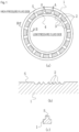
- a sliding part 1 is formed in an annular body.
- a high pressure sealed fluid exists on one side of inner and outer peripheries of a sealing face S of the sliding part 1, and the atmosphere is on the other side.
- This sealed fluid can be effectively sealed by using the sliding part 1.
- This sliding part 1 is used for at least one of a pair of rotating and stationary sealing rings in a mechanical seal device. By closely placing a sealing face of the rotating sealing ring and the opposing sealing face of the stationary sealing ring, a sealed fluid that exists in one of inner and outer peripheries of the sealing faces is sealed.
- a mechanical seal serving as one example of the sliding part will be described as an example.
- an outer peripheral side of the sliding part that forms the mechanical seal serves as a high pressure fluid side (sealed fluid side), and an inner peripheral side serves as a low pressure fluid side (atmosphere side).
- the present invention is a case where the high pressure fluid side and the low pressure fluid side are set the other way around.
- FIG. 1 for convenience of description, a case where the high pressure sealed fluid exists on the outer peripheral side will be described.
- a sectional shape of the sliding part 1 is a convex shape as shown in FIG. 1(c) , and a top face thereof forms the flat sealing face S.
- a large number of dimples 2 as shown in FIG. 1(b) are independently provided on this sealing face S. These dimples 2 are provided not over the entire width in the radial direction of the sealing face S but in dimple formation regions 3 close to the high pressure fluid side.
- the dimple formation regions 3 communicate with the high pressure fluid side and are isolated from the low pressure fluid side by a flat seal face 4.
- the sliding part 1 is made of silicon carbide (SiC).
- the "dimples” are dents formed on the flat sealing face S, and a shape thereof is not particularly limited.
- a sectional shape of the dents also includes various shapes such as a bowl shape or a square shape.
- a large number of dimples 2 formed on the sealing face S have a function of holding part of a liquid placed between this sealing face S and the opposing sealing face that relatively slides on the above sealing face as a hydrodynamic lubricating liquid film so as to stabilize a lubricating liquid film.
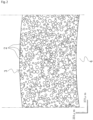
- FIG. 2 is a plan view of the sealing face showing the dimples randomly arranged on the sealing face of the sliding part according to the embodiment of the present invention.
- the same reference signs as the reference signs in FIG. 1 denote the same members as those in FIG. 1 and detailed description thereof will be omitted.
- each of the plurality of dimples 2 formed on the sealing face is provided independently from the other dimples, and arranged in such a manner that the plurality of dimples having different opening diameters is randomly distributed.
- a method of random distribution of the opening diameters of the dimples in the present example, decision is made by using random numbers and the dimples are uniformly distributed on the sealing face. That is, setting is made in such a manner that the distribution of the dimples having different opening diameters is uniform over the entire sealing face.
- FIG. 3 is a chart showing diameter size distribution of the randomly arranged dimples 2 according to the embodiment of the present invention.
- the opening diameters of the plurality of dimples 2 are distributed within a range from 30 to 100 um. More dimples 2 having smaller opening diameters are distributed in comparison to the dimples 2 having larger opening diameters.
- Random distribution of the opening diameters of the plurality of dimples 2 is set in accordance with a bearing characteristic number G (fluid viscosity ⁇ speed / load) of the sealing face or the like.
- FIG. 3 shows one favorable example in the mixed dimples having the opening diameters of 30 to 100 ⁇ m.
- the mixed dimples in which the opening diameters of the dimples 2 are randomly distributed within a range from 30 to 100 um are used.
- the depth of the plurality of dimples 2 is preferably set within a range from 50 to 100 nm from a viewpoint of reduction in a friction coefficient. However, in a case where importance is attached to the sliding characteristic at extremely low speed, the depth is preferably set within a range from 100 to 200 nm.
- FIG. 4 is a chart showing a relationship between the friction coefficient and the bearing characteristic number G obtained by a rotation sliding test.
- the friction coefficient is almost the same as that of the diameter of ⁇ 100 ⁇ m, and within a range of 6.0 ⁇ 10 -8 or less, the Gc point is shifted to the lower G side and further the friction coefficient at the Gc point is lowered. It is found that there is an effect on the reduction in the friction coefficient in a wide rotation number range.
- testing machine 10 capable of measuring sliding torque, the testing machine used in the present test will be described.
- a main body part of the testing machine 10 includes a casing 13 that supports a stationary ring 11 in a non-rotation state via a spring 12, a rotating shaft 14 rotatably inserted in an inner periphery of this casing 13, and a rotating ring 15 supported on an outer periphery of this rotating shaft 14, the rotating ring facing the stationary ring 11 in the axial direction.
- a sealing target liquid L is enclosed into a sealed space surrounded by the rotating ring 15, the casing 13, and the rotating shaft 14.
- hydrostatic gas bearings are adopted as bearing parts 16 on both sides, so that the sliding torque of the mechanical seal can be measured with high precision.
- the torque is measured by two kinds of methods including a torque meter 17 and a cantilever type load cell 18, so as to eliminate measuring errors by double-checking.
- the sliding part is used for at least one of the pair of rotating and stationary sealing rings in the mechanical seal device is described in the above embodiment.
- the sliding part can also be utilized as a sliding part of a bearing that slides on a rotating shaft while sealing lubricating oil on one side in the axial direction of a cylindrical sealing face.
- the case where the high pressure sealed fluid exists on the outer peripheral side is described in the above embodiment.
- the present invention is applied to a case where the high pressure fluid exists on the inner peripheral side.
- the dimples are arranged to communicate with the inner peripheral side.
- the opening diameters of the plurality of dimples are set within a range from 30 to 100 ⁇ m and more dimples having smaller opening diameters are distributed in comparison to the dimples having larger opening diameters is described in the above embodiment.
- these show one preferable example and the present invention is limited to the distribution shown in figure 2 .
- the depth of the plurality of dimples is described in the above embodiment.
- the depth may be selected from a range from 50 to 1,000 nm.
- the depth is desirably set within a range from 100 to 200 nm.
- the present invention is not limited to this but the area ratio may be set within a range from 30 to 50%.
Landscapes
- Engineering & Computer Science (AREA)
- General Engineering & Computer Science (AREA)
- Mechanical Engineering (AREA)
- Chemical & Material Sciences (AREA)
- Oil, Petroleum & Natural Gas (AREA)
- Mechanical Sealing (AREA)
- Sliding-Contact Bearings (AREA)
Claims (1)
- Gleitringdichtung mit einem Paar von Gleitteilen (1), die jeweils einen rotierenden Dichtungsring und einen stationären Dichtungsring der Gleitringdichtung bilden und Dichtungsflächen (S) aufweisen, die relativ zueinander gleiten, wobei mindestens eines der Gleitteile (1) ein ringförmiger Körper ist und eine Vielzahl von Vertiefungen (2) aufweist, die in der Dichtungsfläche (S) ausgebildet sind, wobei die Vielzahl von Vertiefungen (2) planare Formen, wie in Figur 2 gezeigt, aufweist und Vertiefungen (2) enthält, die so angeordnet sind, dass sie mit einer inneren Umfangsseite des Gleitteils (1) in Verbindung stehen, dadurch gekennzeichnet, dass die Vertiefungen (2) Öffnungsdurchmesser, wie in Figur 2 gezeigt, aufweisen und wie in Figur 2 gezeigt verteilt sind.
Applications Claiming Priority (3)
| Application Number | Priority Date | Filing Date | Title |
|---|---|---|---|
| JP2013192868 | 2013-09-18 | ||
| PCT/JP2014/073136 WO2015041048A1 (ja) | 2013-09-18 | 2014-09-03 | しゅう動部品 |
| EP14846352.4A EP3048341A4 (de) | 2013-09-18 | 2014-09-03 | Gleitkomponente |
Related Parent Applications (1)
| Application Number | Title | Priority Date | Filing Date |
|---|---|---|---|
| EP14846352.4A Division EP3048341A4 (de) | 2013-09-18 | 2014-09-03 | Gleitkomponente |
Publications (2)
| Publication Number | Publication Date |
|---|---|
| EP3284982A1 EP3284982A1 (de) | 2018-02-21 |
| EP3284982B1 true EP3284982B1 (de) | 2024-03-20 |
Family
ID=52688702
Family Applications (3)
| Application Number | Title | Priority Date | Filing Date |
|---|---|---|---|
| EP17186079.4A Active EP3284982B1 (de) | 2013-09-18 | 2014-09-03 | Gleitkomponente |
| EP17175219.9A Active EP3244103B1 (de) | 2013-09-18 | 2014-09-03 | Gleitkomponente |
| EP14846352.4A Withdrawn EP3048341A4 (de) | 2013-09-18 | 2014-09-03 | Gleitkomponente |
Family Applications After (2)
| Application Number | Title | Priority Date | Filing Date |
|---|---|---|---|
| EP17175219.9A Active EP3244103B1 (de) | 2013-09-18 | 2014-09-03 | Gleitkomponente |
| EP14846352.4A Withdrawn EP3048341A4 (de) | 2013-09-18 | 2014-09-03 | Gleitkomponente |
Country Status (6)
| Country | Link |
|---|---|
| US (2) | US9829043B2 (de) |
| EP (3) | EP3284982B1 (de) |
| JP (3) | JP6584950B2 (de) |
| CN (3) | CN107269846B (de) |
| AU (1) | AU2014322381B2 (de) |
| WO (1) | WO2015041048A1 (de) |
Families Citing this family (16)
| Publication number | Priority date | Publication date | Assignee | Title |
|---|---|---|---|---|
| FR3009124A1 (fr) * | 2013-07-24 | 2015-01-30 | Areva Np | Glace pour garniture d'etancheite pour systeme d'etancheite d'arbre |
| WO2015031474A1 (en) * | 2013-08-27 | 2015-03-05 | Eaton Corporation | Seal ring composite for improved hydrodynamic seal performance |
| JP6798776B2 (ja) * | 2015-10-16 | 2020-12-09 | 株式会社リケン | シールリング |
| EP3508763A4 (de) * | 2016-09-01 | 2020-04-15 | Eagle Industry Co., Ltd. | Gleitkomponente |
| EP3543552B1 (de) * | 2016-11-18 | 2021-11-10 | Eagle Industry Co., Ltd. | Gleitelemente |
| KR102346413B1 (ko) * | 2017-05-19 | 2022-01-03 | 이구루코교 가부시기가이샤 | 슬라이딩 부품 |
| KR102346395B1 (ko) * | 2017-05-19 | 2022-01-03 | 이구루코교 가부시기가이샤 | 슬라이딩 부품 |
| WO2018212108A1 (ja) * | 2017-05-19 | 2018-11-22 | イーグル工業株式会社 | 摺動部品 |
| JP7143038B2 (ja) | 2017-07-14 | 2022-09-28 | イーグル工業株式会社 | 摺動部品 |
| JP7234123B2 (ja) * | 2017-10-03 | 2023-03-07 | イーグル工業株式会社 | 摺動部品 |
| US20200346829A1 (en) | 2017-10-26 | 2020-11-05 | Threebond Co., Ltd. | Material supply device and spout |
| CN110273921A (zh) * | 2019-06-13 | 2019-09-24 | 天津大学 | 一种全工况复合结构滑动轴承 |
| EP4027028B1 (de) | 2019-09-02 | 2025-07-09 | Eagle Industry Co., Ltd. | Gleitkomponente |
| US12018701B2 (en) * | 2020-09-24 | 2024-06-25 | Flowserve Pte. Ltd. | Hydraulic bearings and related devices, assemblies, and methods |
| JP7606888B2 (ja) * | 2021-03-04 | 2024-12-26 | シチズン時計株式会社 | 情報処理装置、システム、情報処理方法、および画像生成装置 |
| CN113245650B (zh) * | 2021-06-03 | 2022-06-24 | 烟台大学 | 一种脑深部刺激套管电极及其表面毛化的随机仿生微织构制备方法 |
Citations (4)
| Publication number | Priority date | Publication date | Assignee | Title |
|---|---|---|---|---|
| JPH01158853U (de) * | 1988-03-18 | 1989-11-02 | ||
| JPH11287329A (ja) * | 1998-04-03 | 1999-10-19 | Eagle Ind Co Ltd | 摺動材 |
| WO2002093046A1 (en) * | 2001-05-15 | 2002-11-21 | Aes Engineering Limited | Mechanical seal |
| CN200961698Y (zh) * | 2006-10-12 | 2007-10-17 | 河北科技大学 | 一种动压型机械密封环 |
Family Cites Families (32)
| Publication number | Priority date | Publication date | Assignee | Title |
|---|---|---|---|---|
| JPS52149232A (en) | 1976-06-07 | 1977-12-12 | Suzuki Motor Co | Sliding material and method of fabricating the same |
| JPH01158853A (ja) | 1987-12-15 | 1989-06-21 | Sumitomo Electric Ind Ltd | バースト信号検出回路 |
| DE3810741C1 (de) * | 1988-03-30 | 1989-11-09 | Fa. Carl Freudenberg, 6940 Weinheim, De | |
| JP3026252B2 (ja) * | 1995-09-08 | 2000-03-27 | イーグル工業株式会社 | メカニカルシール用摺動材 |
| JPH09292033A (ja) * | 1996-04-26 | 1997-11-11 | Eagle Ind Co Ltd | メカニカルシール |
| JPH11230364A (ja) * | 1998-02-13 | 1999-08-27 | Eagle Ind Co Ltd | 摺動材 |
| JPH11230365A (ja) * | 1998-02-13 | 1999-08-27 | Eagle Ind Co Ltd | 摺動材 |
| JPH11236976A (ja) * | 1998-02-24 | 1999-08-31 | Eagle Ind Co Ltd | 摺動材 |
| JP2000169266A (ja) | 1998-12-04 | 2000-06-20 | Eagle Ind Co Ltd | 摺動材 |
| US6739238B2 (en) * | 2000-11-20 | 2004-05-25 | Nissan Motor Co., Ltd. | Sliding structure for a reciprocating internal combustion engine and a reciprocating internal combustion engine using the sliding structure |
| JP3890495B2 (ja) * | 2000-11-20 | 2007-03-07 | 日産自動車株式会社 | 内燃機関用摺動部品及びそれを用いた内燃機関 |
| JP2003184883A (ja) * | 2001-12-20 | 2003-07-03 | Nissan Motor Co Ltd | 軸受摺動部材 |
| US6902168B2 (en) * | 2002-03-19 | 2005-06-07 | Eagle Industry Co., Ltd. | Sliding element |
| JP4205910B2 (ja) * | 2002-04-02 | 2009-01-07 | イーグル工業株式会社 | 摺動部品 |
| JP4141778B2 (ja) * | 2002-09-24 | 2008-08-27 | イーグル工業株式会社 | 摺動部品及びその製造方法 |
| JP4316956B2 (ja) * | 2002-10-23 | 2009-08-19 | イーグル工業株式会社 | 摺動部品 |
| JP4719414B2 (ja) * | 2003-12-22 | 2011-07-06 | イーグル工業株式会社 | 摺動部品 |
| US7997583B2 (en) | 2005-11-08 | 2011-08-16 | Eagle Industry Co., Ltd. | Mechanical sealing device |
| WO2007058177A1 (ja) * | 2005-11-15 | 2007-05-24 | Nippon Tungsten Co., Ltd. | メカニカルシールリング |
| CN100564962C (zh) * | 2007-02-15 | 2009-12-02 | 浙江工业大学 | 变分布多孔端面机械密封结构 |
| WO2009066664A1 (ja) * | 2007-11-20 | 2009-05-28 | Eagle Industry Co., Ltd. | メカニカルシール及びタンデムシール |
| JP5456772B2 (ja) * | 2009-05-25 | 2014-04-02 | イーグル工業株式会社 | シール装置 |
| CN101672364B (zh) * | 2009-10-15 | 2013-06-05 | 浙江工业大学 | 双列倾斜式方向性微孔端面无泄漏机械密封结构 |
| JP5801034B2 (ja) | 2010-02-01 | 2015-10-28 | 日本航空電子工業株式会社 | 摺動部品、摺動部品表面の加工方法および生産方法 |
| JP5518527B2 (ja) * | 2010-03-04 | 2014-06-11 | イーグル工業株式会社 | 摺動部品 |
| EP2752603B1 (de) * | 2011-09-03 | 2019-10-30 | Eagle Industry Co., Ltd. | Gleitkomponente |
| WO2013031529A1 (ja) * | 2011-09-03 | 2013-03-07 | イーグル工業株式会社 | 摺動部品 |
| US9151390B2 (en) * | 2011-09-10 | 2015-10-06 | Eagle Industry Co., Ltd. | Sliding parts |
| WO2013176009A1 (ja) * | 2012-05-21 | 2013-11-28 | イーグル工業株式会社 | 摺動部品 |
| US9261139B2 (en) * | 2013-02-06 | 2016-02-16 | Trelleborg Sealing Solutions Us | Friction-reducing geometric surface feature |
| EP2964981A2 (de) * | 2013-03-07 | 2016-01-13 | Rolls-Royce Corporation | Dichtungsanordnung und welle dafür |
| AU2014362551B2 (en) * | 2013-12-09 | 2017-06-01 | Eagle Industry Co., Ltd. | Sliding component |
-
2014
- 2014-09-03 AU AU2014322381A patent/AU2014322381B2/en not_active Ceased
- 2014-09-03 JP JP2015537632A patent/JP6584950B2/ja active Active
- 2014-09-03 CN CN201710451397.XA patent/CN107269846B/zh active Active
- 2014-09-03 WO PCT/JP2014/073136 patent/WO2015041048A1/ja not_active Ceased
- 2014-09-03 EP EP17186079.4A patent/EP3284982B1/de active Active
- 2014-09-03 EP EP17175219.9A patent/EP3244103B1/de active Active
- 2014-09-03 CN CN201710492554.1A patent/CN107269705B/zh active Active
- 2014-09-03 EP EP14846352.4A patent/EP3048341A4/de not_active Withdrawn
- 2014-09-03 US US14/900,064 patent/US9829043B2/en active Active
- 2014-09-03 CN CN201480038978.5A patent/CN105358884B/zh active Active
-
2017
- 2017-04-10 US US15/483,915 patent/US9915289B2/en active Active
- 2017-05-24 JP JP2017102458A patent/JP6800089B2/ja active Active
- 2017-07-20 JP JP2017140667A patent/JP2017207209A/ja active Pending
Patent Citations (4)
| Publication number | Priority date | Publication date | Assignee | Title |
|---|---|---|---|---|
| JPH01158853U (de) * | 1988-03-18 | 1989-11-02 | ||
| JPH11287329A (ja) * | 1998-04-03 | 1999-10-19 | Eagle Ind Co Ltd | 摺動材 |
| WO2002093046A1 (en) * | 2001-05-15 | 2002-11-21 | Aes Engineering Limited | Mechanical seal |
| CN200961698Y (zh) * | 2006-10-12 | 2007-10-17 | 河北科技大学 | 一种动压型机械密封环 |
Also Published As
| Publication number | Publication date |
|---|---|
| CN105358884A (zh) | 2016-02-24 |
| CN105358884B (zh) | 2017-10-24 |
| JP2017207209A (ja) | 2017-11-24 |
| US20160195139A1 (en) | 2016-07-07 |
| JP2017166701A (ja) | 2017-09-21 |
| EP3048341A4 (de) | 2017-04-26 |
| US9915289B2 (en) | 2018-03-13 |
| US9829043B2 (en) | 2017-11-28 |
| CN107269846B (zh) | 2020-01-21 |
| EP3048341A1 (de) | 2016-07-27 |
| AU2014322381B2 (en) | 2017-01-12 |
| EP3244103A1 (de) | 2017-11-15 |
| JPWO2015041048A1 (ja) | 2017-03-02 |
| CN107269705A (zh) | 2017-10-20 |
| WO2015041048A1 (ja) | 2015-03-26 |
| EP3284982A1 (de) | 2018-02-21 |
| JP6584950B2 (ja) | 2019-10-02 |
| US20170227056A1 (en) | 2017-08-10 |
| EP3244103B1 (de) | 2020-12-02 |
| CN107269846A (zh) | 2017-10-20 |
| CN107269705B (zh) | 2019-06-18 |
| JP6800089B2 (ja) | 2020-12-16 |
| AU2014322381A1 (en) | 2016-01-28 |
Similar Documents
| Publication | Publication Date | Title |
|---|---|---|
| EP3284982B1 (de) | Gleitkomponente | |
| EP3508763A1 (de) | Gleitkomponente | |
| EP3258145B1 (de) | Gleitkomponente | |
| US9970478B2 (en) | Sliding parts | |
| JP4205910B2 (ja) | 摺動部品 | |
| JP6076971B2 (ja) | 摺動部品 | |
| US9383017B2 (en) | Tapered channel macro/micro feature for mechanical face seals | |
| JPWO2009087995A1 (ja) | メカニカルシール摺動材及びメカニカルシール | |
| JPWO2016143721A1 (ja) | しゅう動部品 | |
| JPH11287329A (ja) | 摺動材 |
Legal Events
| Date | Code | Title | Description |
|---|---|---|---|
| PUAI | Public reference made under article 153(3) epc to a published international application that has entered the european phase |
Free format text: ORIGINAL CODE: 0009012 |
|
| STAA | Information on the status of an ep patent application or granted ep patent |
Free format text: STATUS: THE APPLICATION HAS BEEN PUBLISHED |
|
| AC | Divisional application: reference to earlier application |
Ref document number: 3048341 Country of ref document: EP Kind code of ref document: P |
|
| AK | Designated contracting states |
Kind code of ref document: A1 Designated state(s): AL AT BE BG CH CY CZ DE DK EE ES FI FR GB GR HR HU IE IS IT LI LT LU LV MC MK MT NL NO PL PT RO RS SE SI SK SM TR |
|
| RIN1 | Information on inventor provided before grant (corrected) |
Inventor name: HOSOE, TAKESHI Inventor name: INOUE, HIDEYUKI Inventor name: NEGISHI, YUTA Inventor name: TOKUNAGA, YUUICHIRO |
|
| STAA | Information on the status of an ep patent application or granted ep patent |
Free format text: STATUS: REQUEST FOR EXAMINATION WAS MADE |
|
| 17P | Request for examination filed |
Effective date: 20180806 |
|
| RBV | Designated contracting states (corrected) |
Designated state(s): AL AT BE BG CH CY CZ DE DK EE ES FI FR GB GR HR HU IE IS IT LI LT LU LV MC MK MT NL NO PL PT RO RS SE SI SK SM TR |
|
| STAA | Information on the status of an ep patent application or granted ep patent |
Free format text: STATUS: EXAMINATION IS IN PROGRESS |
|
| 17Q | First examination report despatched |
Effective date: 20220103 |
|
| GRAP | Despatch of communication of intention to grant a patent |
Free format text: ORIGINAL CODE: EPIDOSNIGR1 |
|
| STAA | Information on the status of an ep patent application or granted ep patent |
Free format text: STATUS: GRANT OF PATENT IS INTENDED |
|
| INTG | Intention to grant announced |
Effective date: 20231026 |
|
| GRAS | Grant fee paid |
Free format text: ORIGINAL CODE: EPIDOSNIGR3 |
|
| GRAA | (expected) grant |
Free format text: ORIGINAL CODE: 0009210 |
|
| STAA | Information on the status of an ep patent application or granted ep patent |
Free format text: STATUS: THE PATENT HAS BEEN GRANTED |
|
| AC | Divisional application: reference to earlier application |
Ref document number: 3048341 Country of ref document: EP Kind code of ref document: P |
|
| AK | Designated contracting states |
Kind code of ref document: B1 Designated state(s): AL AT BE BG CH CY CZ DE DK EE ES FI FR GB GR HR HU IE IS IT LI LT LU LV MC MK MT NL NO PL PT RO RS SE SI SK SM TR |
|
| REG | Reference to a national code |
Ref country code: GB Ref legal event code: FG4D |
|
| REG | Reference to a national code |
Ref country code: CH Ref legal event code: EP |
|
| REG | Reference to a national code |
Ref country code: IE Ref legal event code: FG4D |
|
| REG | Reference to a national code |
Ref country code: DE Ref legal event code: R096 Ref document number: 602014089756 Country of ref document: DE |
|
| PG25 | Lapsed in a contracting state [announced via postgrant information from national office to epo] |
Ref country code: LT Free format text: LAPSE BECAUSE OF FAILURE TO SUBMIT A TRANSLATION OF THE DESCRIPTION OR TO PAY THE FEE WITHIN THE PRESCRIBED TIME-LIMIT Effective date: 20240320 |
|
| REG | Reference to a national code |
Ref country code: LT Ref legal event code: MG9D |
|
| PG25 | Lapsed in a contracting state [announced via postgrant information from national office to epo] |
Ref country code: GR Free format text: LAPSE BECAUSE OF FAILURE TO SUBMIT A TRANSLATION OF THE DESCRIPTION OR TO PAY THE FEE WITHIN THE PRESCRIBED TIME-LIMIT Effective date: 20240621 |
|
| PG25 | Lapsed in a contracting state [announced via postgrant information from national office to epo] |
Ref country code: RS Free format text: LAPSE BECAUSE OF FAILURE TO SUBMIT A TRANSLATION OF THE DESCRIPTION OR TO PAY THE FEE WITHIN THE PRESCRIBED TIME-LIMIT Effective date: 20240620 Ref country code: HR Free format text: LAPSE BECAUSE OF FAILURE TO SUBMIT A TRANSLATION OF THE DESCRIPTION OR TO PAY THE FEE WITHIN THE PRESCRIBED TIME-LIMIT Effective date: 20240320 |
|
| REG | Reference to a national code |
Ref country code: NL Ref legal event code: MP Effective date: 20240320 |
|
| PG25 | Lapsed in a contracting state [announced via postgrant information from national office to epo] |
Ref country code: RS Free format text: LAPSE BECAUSE OF FAILURE TO SUBMIT A TRANSLATION OF THE DESCRIPTION OR TO PAY THE FEE WITHIN THE PRESCRIBED TIME-LIMIT Effective date: 20240620 Ref country code: NO Free format text: LAPSE BECAUSE OF FAILURE TO SUBMIT A TRANSLATION OF THE DESCRIPTION OR TO PAY THE FEE WITHIN THE PRESCRIBED TIME-LIMIT Effective date: 20240620 Ref country code: LT Free format text: LAPSE BECAUSE OF FAILURE TO SUBMIT A TRANSLATION OF THE DESCRIPTION OR TO PAY THE FEE WITHIN THE PRESCRIBED TIME-LIMIT Effective date: 20240320 Ref country code: HR Free format text: LAPSE BECAUSE OF FAILURE TO SUBMIT A TRANSLATION OF THE DESCRIPTION OR TO PAY THE FEE WITHIN THE PRESCRIBED TIME-LIMIT Effective date: 20240320 Ref country code: GR Free format text: LAPSE BECAUSE OF FAILURE TO SUBMIT A TRANSLATION OF THE DESCRIPTION OR TO PAY THE FEE WITHIN THE PRESCRIBED TIME-LIMIT Effective date: 20240621 Ref country code: FI Free format text: LAPSE BECAUSE OF FAILURE TO SUBMIT A TRANSLATION OF THE DESCRIPTION OR TO PAY THE FEE WITHIN THE PRESCRIBED TIME-LIMIT Effective date: 20240320 Ref country code: BG Free format text: LAPSE BECAUSE OF FAILURE TO SUBMIT A TRANSLATION OF THE DESCRIPTION OR TO PAY THE FEE WITHIN THE PRESCRIBED TIME-LIMIT Effective date: 20240320 |
|
| REG | Reference to a national code |
Ref country code: AT Ref legal event code: MK05 Ref document number: 1668082 Country of ref document: AT Kind code of ref document: T Effective date: 20240320 |
|
| PG25 | Lapsed in a contracting state [announced via postgrant information from national office to epo] |
Ref country code: SE Free format text: LAPSE BECAUSE OF FAILURE TO SUBMIT A TRANSLATION OF THE DESCRIPTION OR TO PAY THE FEE WITHIN THE PRESCRIBED TIME-LIMIT Effective date: 20240320 Ref country code: LV Free format text: LAPSE BECAUSE OF FAILURE TO SUBMIT A TRANSLATION OF THE DESCRIPTION OR TO PAY THE FEE WITHIN THE PRESCRIBED TIME-LIMIT Effective date: 20240320 |
|
| PG25 | Lapsed in a contracting state [announced via postgrant information from national office to epo] |
Ref country code: NL Free format text: LAPSE BECAUSE OF FAILURE TO SUBMIT A TRANSLATION OF THE DESCRIPTION OR TO PAY THE FEE WITHIN THE PRESCRIBED TIME-LIMIT Effective date: 20240320 |
|
| PG25 | Lapsed in a contracting state [announced via postgrant information from national office to epo] |
Ref country code: NL Free format text: LAPSE BECAUSE OF FAILURE TO SUBMIT A TRANSLATION OF THE DESCRIPTION OR TO PAY THE FEE WITHIN THE PRESCRIBED TIME-LIMIT Effective date: 20240320 |
|
| PG25 | Lapsed in a contracting state [announced via postgrant information from national office to epo] |
Ref country code: IS Free format text: LAPSE BECAUSE OF FAILURE TO SUBMIT A TRANSLATION OF THE DESCRIPTION OR TO PAY THE FEE WITHIN THE PRESCRIBED TIME-LIMIT Effective date: 20240720 |
|
| PG25 | Lapsed in a contracting state [announced via postgrant information from national office to epo] |
Ref country code: SM Free format text: LAPSE BECAUSE OF FAILURE TO SUBMIT A TRANSLATION OF THE DESCRIPTION OR TO PAY THE FEE WITHIN THE PRESCRIBED TIME-LIMIT Effective date: 20240320 Ref country code: PT Free format text: LAPSE BECAUSE OF FAILURE TO SUBMIT A TRANSLATION OF THE DESCRIPTION OR TO PAY THE FEE WITHIN THE PRESCRIBED TIME-LIMIT Effective date: 20240722 |
|
| PG25 | Lapsed in a contracting state [announced via postgrant information from national office to epo] |
Ref country code: ES Free format text: LAPSE BECAUSE OF FAILURE TO SUBMIT A TRANSLATION OF THE DESCRIPTION OR TO PAY THE FEE WITHIN THE PRESCRIBED TIME-LIMIT Effective date: 20240320 |
|
| PG25 | Lapsed in a contracting state [announced via postgrant information from national office to epo] |
Ref country code: EE Free format text: LAPSE BECAUSE OF FAILURE TO SUBMIT A TRANSLATION OF THE DESCRIPTION OR TO PAY THE FEE WITHIN THE PRESCRIBED TIME-LIMIT Effective date: 20240320 Ref country code: CZ Free format text: LAPSE BECAUSE OF FAILURE TO SUBMIT A TRANSLATION OF THE DESCRIPTION OR TO PAY THE FEE WITHIN THE PRESCRIBED TIME-LIMIT Effective date: 20240320 |
|
| PG25 | Lapsed in a contracting state [announced via postgrant information from national office to epo] |
Ref country code: AT Free format text: LAPSE BECAUSE OF FAILURE TO SUBMIT A TRANSLATION OF THE DESCRIPTION OR TO PAY THE FEE WITHIN THE PRESCRIBED TIME-LIMIT Effective date: 20240320 |
|
| PG25 | Lapsed in a contracting state [announced via postgrant information from national office to epo] |
Ref country code: PL Free format text: LAPSE BECAUSE OF FAILURE TO SUBMIT A TRANSLATION OF THE DESCRIPTION OR TO PAY THE FEE WITHIN THE PRESCRIBED TIME-LIMIT Effective date: 20240320 |
|
| PG25 | Lapsed in a contracting state [announced via postgrant information from national office to epo] |
Ref country code: SK Free format text: LAPSE BECAUSE OF FAILURE TO SUBMIT A TRANSLATION OF THE DESCRIPTION OR TO PAY THE FEE WITHIN THE PRESCRIBED TIME-LIMIT Effective date: 20240320 |
|
| PG25 | Lapsed in a contracting state [announced via postgrant information from national office to epo] |
Ref country code: SM Free format text: LAPSE BECAUSE OF FAILURE TO SUBMIT A TRANSLATION OF THE DESCRIPTION OR TO PAY THE FEE WITHIN THE PRESCRIBED TIME-LIMIT Effective date: 20240320 Ref country code: SK Free format text: LAPSE BECAUSE OF FAILURE TO SUBMIT A TRANSLATION OF THE DESCRIPTION OR TO PAY THE FEE WITHIN THE PRESCRIBED TIME-LIMIT Effective date: 20240320 Ref country code: RO Free format text: LAPSE BECAUSE OF FAILURE TO SUBMIT A TRANSLATION OF THE DESCRIPTION OR TO PAY THE FEE WITHIN THE PRESCRIBED TIME-LIMIT Effective date: 20240320 Ref country code: PT Free format text: LAPSE BECAUSE OF FAILURE TO SUBMIT A TRANSLATION OF THE DESCRIPTION OR TO PAY THE FEE WITHIN THE PRESCRIBED TIME-LIMIT Effective date: 20240722 Ref country code: PL Free format text: LAPSE BECAUSE OF FAILURE TO SUBMIT A TRANSLATION OF THE DESCRIPTION OR TO PAY THE FEE WITHIN THE PRESCRIBED TIME-LIMIT Effective date: 20240320 Ref country code: IS Free format text: LAPSE BECAUSE OF FAILURE TO SUBMIT A TRANSLATION OF THE DESCRIPTION OR TO PAY THE FEE WITHIN THE PRESCRIBED TIME-LIMIT Effective date: 20240720 Ref country code: ES Free format text: LAPSE BECAUSE OF FAILURE TO SUBMIT A TRANSLATION OF THE DESCRIPTION OR TO PAY THE FEE WITHIN THE PRESCRIBED TIME-LIMIT Effective date: 20240320 Ref country code: EE Free format text: LAPSE BECAUSE OF FAILURE TO SUBMIT A TRANSLATION OF THE DESCRIPTION OR TO PAY THE FEE WITHIN THE PRESCRIBED TIME-LIMIT Effective date: 20240320 Ref country code: CZ Free format text: LAPSE BECAUSE OF FAILURE TO SUBMIT A TRANSLATION OF THE DESCRIPTION OR TO PAY THE FEE WITHIN THE PRESCRIBED TIME-LIMIT Effective date: 20240320 Ref country code: AT Free format text: LAPSE BECAUSE OF FAILURE TO SUBMIT A TRANSLATION OF THE DESCRIPTION OR TO PAY THE FEE WITHIN THE PRESCRIBED TIME-LIMIT Effective date: 20240320 |
|
| PG25 | Lapsed in a contracting state [announced via postgrant information from national office to epo] |
Ref country code: IT Free format text: LAPSE BECAUSE OF FAILURE TO SUBMIT A TRANSLATION OF THE DESCRIPTION OR TO PAY THE FEE WITHIN THE PRESCRIBED TIME-LIMIT Effective date: 20240320 |
|
| REG | Reference to a national code |
Ref country code: DE Ref legal event code: R097 Ref document number: 602014089756 Country of ref document: DE |
|
| PG25 | Lapsed in a contracting state [announced via postgrant information from national office to epo] |
Ref country code: IT Free format text: LAPSE BECAUSE OF FAILURE TO SUBMIT A TRANSLATION OF THE DESCRIPTION OR TO PAY THE FEE WITHIN THE PRESCRIBED TIME-LIMIT Effective date: 20240320 |
|
| PG25 | Lapsed in a contracting state [announced via postgrant information from national office to epo] |
Ref country code: DK Free format text: LAPSE BECAUSE OF FAILURE TO SUBMIT A TRANSLATION OF THE DESCRIPTION OR TO PAY THE FEE WITHIN THE PRESCRIBED TIME-LIMIT Effective date: 20240320 |
|
| PLBE | No opposition filed within time limit |
Free format text: ORIGINAL CODE: 0009261 |
|
| STAA | Information on the status of an ep patent application or granted ep patent |
Free format text: STATUS: NO OPPOSITION FILED WITHIN TIME LIMIT |
|
| PG25 | Lapsed in a contracting state [announced via postgrant information from national office to epo] |
Ref country code: DK Free format text: LAPSE BECAUSE OF FAILURE TO SUBMIT A TRANSLATION OF THE DESCRIPTION OR TO PAY THE FEE WITHIN THE PRESCRIBED TIME-LIMIT Effective date: 20240320 |
|
| 26N | No opposition filed |
Effective date: 20241223 |
|
| PG25 | Lapsed in a contracting state [announced via postgrant information from national office to epo] |
Ref country code: SI Free format text: LAPSE BECAUSE OF FAILURE TO SUBMIT A TRANSLATION OF THE DESCRIPTION OR TO PAY THE FEE WITHIN THE PRESCRIBED TIME-LIMIT Effective date: 20240320 Ref country code: MC Free format text: LAPSE BECAUSE OF FAILURE TO SUBMIT A TRANSLATION OF THE DESCRIPTION OR TO PAY THE FEE WITHIN THE PRESCRIBED TIME-LIMIT Effective date: 20240320 |
|
| REG | Reference to a national code |
Ref country code: CH Ref legal event code: PL |
|
| PG25 | Lapsed in a contracting state [announced via postgrant information from national office to epo] |
Ref country code: LU Free format text: LAPSE BECAUSE OF NON-PAYMENT OF DUE FEES Effective date: 20240903 |
|
| GBPC | Gb: european patent ceased through non-payment of renewal fee |
Effective date: 20240903 |
|
| PG25 | Lapsed in a contracting state [announced via postgrant information from national office to epo] |
Ref country code: GB Free format text: LAPSE BECAUSE OF NON-PAYMENT OF DUE FEES Effective date: 20240903 |
|
| REG | Reference to a national code |
Ref country code: BE Ref legal event code: MM Effective date: 20240930 |
|
| PG25 | Lapsed in a contracting state [announced via postgrant information from national office to epo] |
Ref country code: BE Free format text: LAPSE BECAUSE OF NON-PAYMENT OF DUE FEES Effective date: 20240930 |
|
| PG25 | Lapsed in a contracting state [announced via postgrant information from national office to epo] |
Ref country code: FR Free format text: LAPSE BECAUSE OF NON-PAYMENT OF DUE FEES Effective date: 20240930 |
|
| PG25 | Lapsed in a contracting state [announced via postgrant information from national office to epo] |
Ref country code: CH Free format text: LAPSE BECAUSE OF NON-PAYMENT OF DUE FEES Effective date: 20240930 |
|
| PG25 | Lapsed in a contracting state [announced via postgrant information from national office to epo] |
Ref country code: IE Free format text: LAPSE BECAUSE OF NON-PAYMENT OF DUE FEES Effective date: 20240903 |
|
| PGFP | Annual fee paid to national office [announced via postgrant information from national office to epo] |
Ref country code: DE Payment date: 20250730 Year of fee payment: 12 |
|
| PG25 | Lapsed in a contracting state [announced via postgrant information from national office to epo] |
Ref country code: CY Free format text: LAPSE BECAUSE OF FAILURE TO SUBMIT A TRANSLATION OF THE DESCRIPTION OR TO PAY THE FEE WITHIN THE PRESCRIBED TIME-LIMIT; INVALID AB INITIO Effective date: 20140903 |
|
| PG25 | Lapsed in a contracting state [announced via postgrant information from national office to epo] |
Ref country code: HU Free format text: LAPSE BECAUSE OF FAILURE TO SUBMIT A TRANSLATION OF THE DESCRIPTION OR TO PAY THE FEE WITHIN THE PRESCRIBED TIME-LIMIT; INVALID AB INITIO Effective date: 20140903 |