EP3285387A1 - Dispositif de commande d'un convertisseur de conditionneur d'air - Google Patents
Dispositif de commande d'un convertisseur de conditionneur d'air Download PDFInfo
- Publication number
- EP3285387A1 EP3285387A1 EP16779902.2A EP16779902A EP3285387A1 EP 3285387 A1 EP3285387 A1 EP 3285387A1 EP 16779902 A EP16779902 A EP 16779902A EP 3285387 A1 EP3285387 A1 EP 3285387A1
- Authority
- EP
- European Patent Office
- Prior art keywords
- inverter
- drive circuit
- mechanical relay
- drive
- power supply
- Prior art date
- Legal status (The legal status is an assumption and is not a legal conclusion. Google has not performed a legal analysis and makes no representation as to the accuracy of the status listed.)
- Withdrawn
Links
Images
Classifications
-
- H—ELECTRICITY
- H02—GENERATION; CONVERSION OR DISTRIBUTION OF ELECTRIC POWER
- H02M—APPARATUS FOR CONVERSION BETWEEN AC AND AC, BETWEEN AC AND DC, OR BETWEEN DC AND DC, AND FOR USE WITH MAINS OR SIMILAR POWER SUPPLY SYSTEMS; CONVERSION OF DC OR AC INPUT POWER INTO SURGE OUTPUT POWER; CONTROL OR REGULATION THEREOF
- H02M1/00—Details of apparatus for conversion
- H02M1/0003—Details of control, feedback or regulation circuits
- H02M1/0006—Arrangements for supplying an adequate voltage to the control circuit of converters
-
- F—MECHANICAL ENGINEERING; LIGHTING; HEATING; WEAPONS; BLASTING
- F24—HEATING; RANGES; VENTILATING
- F24F—AIR-CONDITIONING; AIR-HUMIDIFICATION; VENTILATION; USE OF AIR CURRENTS FOR SCREENING
- F24F11/00—Control or safety arrangements
- F24F11/30—Control or safety arrangements for purposes related to the operation of the system, e.g. for safety or monitoring
- F24F11/32—Responding to malfunctions or emergencies
-
- F—MECHANICAL ENGINEERING; LIGHTING; HEATING; WEAPONS; BLASTING
- F24—HEATING; RANGES; VENTILATING
- F24F—AIR-CONDITIONING; AIR-HUMIDIFICATION; VENTILATION; USE OF AIR CURRENTS FOR SCREENING
- F24F11/00—Control or safety arrangements
- F24F11/70—Control systems characterised by their outputs; Constructional details thereof
- F24F11/80—Control systems characterised by their outputs; Constructional details thereof for controlling the temperature of the supplied air
- F24F11/86—Control systems characterised by their outputs; Constructional details thereof for controlling the temperature of the supplied air by controlling compressors within refrigeration or heat pump circuits
-
- F—MECHANICAL ENGINEERING; LIGHTING; HEATING; WEAPONS; BLASTING
- F24—HEATING; RANGES; VENTILATING
- F24F—AIR-CONDITIONING; AIR-HUMIDIFICATION; VENTILATION; USE OF AIR CURRENTS FOR SCREENING
- F24F11/00—Control or safety arrangements
- F24F11/89—Arrangement or mounting of control or safety devices
-
- F—MECHANICAL ENGINEERING; LIGHTING; HEATING; WEAPONS; BLASTING
- F25—REFRIGERATION OR COOLING; COMBINED HEATING AND REFRIGERATION SYSTEMS; HEAT PUMP SYSTEMS; MANUFACTURE OR STORAGE OF ICE; LIQUEFACTION SOLIDIFICATION OF GASES
- F25B—REFRIGERATION MACHINES, PLANTS OR SYSTEMS; COMBINED HEATING AND REFRIGERATION SYSTEMS; HEAT PUMP SYSTEMS
- F25B49/00—Arrangement or mounting of control or safety devices
- F25B49/02—Arrangement or mounting of control or safety devices for compression type machines, plants or systems
- F25B49/022—Compressor control arrangements
-
- H—ELECTRICITY
- H02—GENERATION; CONVERSION OR DISTRIBUTION OF ELECTRIC POWER
- H02M—APPARATUS FOR CONVERSION BETWEEN AC AND AC, BETWEEN AC AND DC, OR BETWEEN DC AND DC, AND FOR USE WITH MAINS OR SIMILAR POWER SUPPLY SYSTEMS; CONVERSION OF DC OR AC INPUT POWER INTO SURGE OUTPUT POWER; CONTROL OR REGULATION THEREOF
- H02M1/00—Details of apparatus for conversion
- H02M1/32—Means for protecting converters other than automatic disconnection
-
- H—ELECTRICITY
- H02—GENERATION; CONVERSION OR DISTRIBUTION OF ELECTRIC POWER
- H02M—APPARATUS FOR CONVERSION BETWEEN AC AND AC, BETWEEN AC AND DC, OR BETWEEN DC AND DC, AND FOR USE WITH MAINS OR SIMILAR POWER SUPPLY SYSTEMS; CONVERSION OF DC OR AC INPUT POWER INTO SURGE OUTPUT POWER; CONTROL OR REGULATION THEREOF
- H02M7/00—Conversion of AC power input into DC power output; Conversion of DC power input into AC power output
- H02M7/42—Conversion of DC power input into AC power output without possibility of reversal
- H02M7/44—Conversion of DC power input into AC power output without possibility of reversal by static converters
- H02M7/48—Conversion of DC power input into AC power output without possibility of reversal by static converters using discharge tubes with control electrode or semiconductor devices with control electrode
-
- H—ELECTRICITY
- H02—GENERATION; CONVERSION OR DISTRIBUTION OF ELECTRIC POWER
- H02P—CONTROL OR REGULATION OF ELECTRIC MOTORS, ELECTRIC GENERATORS OR DYNAMO-ELECTRIC CONVERTERS; CONTROLLING TRANSFORMERS, REACTORS OR CHOKE COILS
- H02P27/00—Arrangements or methods for the control of AC motors characterised by the kind of supply voltage
- H02P27/04—Arrangements or methods for the control of AC motors characterised by the kind of supply voltage using variable-frequency supply voltage, e.g. inverter or converter supply voltage
- H02P27/06—Arrangements or methods for the control of AC motors characterised by the kind of supply voltage using variable-frequency supply voltage, e.g. inverter or converter supply voltage using DC to AC converters or inverters
- H02P27/08—Arrangements or methods for the control of AC motors characterised by the kind of supply voltage using variable-frequency supply voltage, e.g. inverter or converter supply voltage using DC to AC converters or inverters with pulse width modulation
-
- H—ELECTRICITY
- H02—GENERATION; CONVERSION OR DISTRIBUTION OF ELECTRIC POWER
- H02P—CONTROL OR REGULATION OF ELECTRIC MOTORS, ELECTRIC GENERATORS OR DYNAMO-ELECTRIC CONVERTERS; CONTROLLING TRANSFORMERS, REACTORS OR CHOKE COILS
- H02P29/00—Arrangements for regulating or controlling electric motors, appropriate for both AC and DC motors
- H02P29/02—Providing protection against overload without automatic interruption of supply
- H02P29/024—Detecting a fault condition, e.g. short circuit, locked rotor, open circuit or loss of load
- H02P29/0241—Detecting a fault condition, e.g. short circuit, locked rotor, open circuit or loss of load the fault being an overvoltage
-
- H—ELECTRICITY
- H02—GENERATION; CONVERSION OR DISTRIBUTION OF ELECTRIC POWER
- H02P—CONTROL OR REGULATION OF ELECTRIC MOTORS, ELECTRIC GENERATORS OR DYNAMO-ELECTRIC CONVERTERS; CONTROLLING TRANSFORMERS, REACTORS OR CHOKE COILS
- H02P3/00—Arrangements for stopping or slowing electric motors, generators, or dynamo-electric converters
- H02P3/06—Arrangements for stopping or slowing electric motors, generators, or dynamo-electric converters for stopping or slowing an individual dynamo-electric motor or dynamo-electric converter
- H02P3/18—Arrangements for stopping or slowing electric motors, generators, or dynamo-electric converters for stopping or slowing an individual dynamo-electric motor or dynamo-electric converter for stopping or slowing an AC motor
-
- F—MECHANICAL ENGINEERING; LIGHTING; HEATING; WEAPONS; BLASTING
- F24—HEATING; RANGES; VENTILATING
- F24F—AIR-CONDITIONING; AIR-HUMIDIFICATION; VENTILATION; USE OF AIR CURRENTS FOR SCREENING
- F24F2140/00—Control inputs relating to system states
- F24F2140/10—Pressure
-
- H—ELECTRICITY
- H02—GENERATION; CONVERSION OR DISTRIBUTION OF ELECTRIC POWER
- H02M—APPARATUS FOR CONVERSION BETWEEN AC AND AC, BETWEEN AC AND DC, OR BETWEEN DC AND DC, AND FOR USE WITH MAINS OR SIMILAR POWER SUPPLY SYSTEMS; CONVERSION OF DC OR AC INPUT POWER INTO SURGE OUTPUT POWER; CONTROL OR REGULATION THEREOF
- H02M5/00—Conversion of AC power input into AC power output, e.g. for change of voltage, for change of frequency, for change of number of phases
- H02M5/40—Conversion of AC power input into AC power output, e.g. for change of voltage, for change of frequency, for change of number of phases with intermediate conversion into DC
- H02M5/42—Conversion of AC power input into AC power output, e.g. for change of voltage, for change of frequency, for change of number of phases with intermediate conversion into DC by static converters
- H02M5/44—Conversion of AC power input into AC power output, e.g. for change of voltage, for change of frequency, for change of number of phases with intermediate conversion into DC by static converters using discharge tubes or semiconductor devices to convert the intermediate DC into AC
- H02M5/453—Conversion of AC power input into AC power output, e.g. for change of voltage, for change of frequency, for change of number of phases with intermediate conversion into DC by static converters using discharge tubes or semiconductor devices to convert the intermediate DC into AC using devices of a triode or transistor type requiring continuous application of a control signal
- H02M5/458—Conversion of AC power input into AC power output, e.g. for change of voltage, for change of frequency, for change of number of phases with intermediate conversion into DC by static converters using discharge tubes or semiconductor devices to convert the intermediate DC into AC using devices of a triode or transistor type requiring continuous application of a control signal using semiconductor devices only
-
- H—ELECTRICITY
- H02—GENERATION; CONVERSION OR DISTRIBUTION OF ELECTRIC POWER
- H02P—CONTROL OR REGULATION OF ELECTRIC MOTORS, ELECTRIC GENERATORS OR DYNAMO-ELECTRIC CONVERTERS; CONTROLLING TRANSFORMERS, REACTORS OR CHOKE COILS
- H02P27/00—Arrangements or methods for the control of AC motors characterised by the kind of supply voltage
- H02P27/04—Arrangements or methods for the control of AC motors characterised by the kind of supply voltage using variable-frequency supply voltage, e.g. inverter or converter supply voltage
- H02P27/06—Arrangements or methods for the control of AC motors characterised by the kind of supply voltage using variable-frequency supply voltage, e.g. inverter or converter supply voltage using DC to AC converters or inverters
Definitions
- the present invention relates to an inverter driver of an air conditioner that drives an inverter of an actuator provided in an air conditioner.
- Air conditioners in recent years have been using many inverter-driven actuators, such as motors driven by inverters.
- inverter-driven actuators such as motors driven by inverters.
- a compressor is rotated by a motor that is driven by an inverter.
- air conditioners where the inverter of the inverter-driven compressor is controlled by a microcomputer, such as disclosed in patent document 1 ( JP-ANo. 2007-107781 ) and patent document 2 (Japanese Patent No. 4,151,188 ).
- a semiconductor device is used to change the inverter drive waveform signal of the microcomputer, and a semiconductor device is also used when forcibly cutting off the supply of the drive voltage to the inverter. In this way, if a semiconductor device is used to stop the compressor when an abnormality has been sensed, the certainty with which the compressor is stopped ends up being dependent on the reliability of the semiconductor device.
- An inverter driver of an air conditioner pertaining to a first aspect of the invention is an inverter driver that drives an inverter of an actuator that actuates the air conditioner, the inverter driver comprising: a drive circuit outputting a drive signal to the inverter; a microcomputer controlling the drive circuit; a first mechanical relay being connected to the drive circuit capable of cutting off an inverter drive power supply of the drive circuit or capable of cutting off the drive signal of the drive circuit; and an inverter control power supply continuing supplying power to the microcomputer, wherein the first mechanical relay cuts off the inverter drive power supply of the drive circuit or the drive signal of the drive circuit when an abnormality in the air conditioner has been sensed and stopping the driving of the actuator has been requested.
- the inverter drive power supply or the drive signal of the drive circuit is cut off by the first mechanical relay when an abnormality has been detected in the air conditioner and stopping the driving of the actuator has been requested, so contacts switch to a mechanically unconnected state because the contacts are mechanically opened and closed inside the first mechanical relay.
- the drive signal with respect to the inverter is certainly changed as a result of the contacts becoming mechanically opened inside the first mechanical relay, and the inverter that had been driven is certainly stopped.
- An inverter drive of the air conditioner pertaining to a second aspect of the invention is the inverter driver pertaining to the first aspect, further comprising an abnormality notification signal transmission circuit transmitting an abnormality notification signal to the microcomputer, wherein the first mechanical relay includes a common contact connected to the inverter drive power supply of the drive circuit, a break contact connected to the drive circuit, and a make contact connected to the abnormality notification signal transmission circuit.
- the first mechanical relay is configured to include the common contact connected to the inverter drive power supply of the drive circuit, the break contact connected to the drive circuit, and the make contact connected to the abnormality notification signal transmission circuit, so abnormality sensing can be swiftly and certainly performed, and the microcomputer can be reduced from erroneously sensing an abnormality other than an abnormality involving the first mechanical relay.
- An inverter driver of the air conditioner pertaining to a third aspect of the invention is the inverter driver pertaining to the first aspect or the second aspect, further comprising a first connection port actuating the first mechanical relay to open when a stop request regarding the actuator has been received and thereby disconnect the inverter drive power supply of the drive circuit or the drive signal of the drive circuit.
- the inverter driver of the third aspect further comprises the first connection port, so a device one wants to have output a request to stop the driving of the actuator can be connected to the first connection port, and the first mechanical relay can be actuated in such a way that ordinarily the first connection port is closed by that device and when an abnormality has been detected the first connection port is opened by that device to disconnect the inverter drive power supply of the drive circuit or the drive signal of the drive circuit.
- An inverter driver of the air conditioner pertaining to a fourth aspect of the invention is the inverter driver pertaining to the third aspect, further comprising: a second mechanical relay connected to the first connection port and receives a stop request regarding the actuator; and a first board and a second board that are separate from each other and to which the first mechanical relay and the second mechanical relay are respectively attached.
- the first mechanical relay is attached to the first board
- the second mechanical relay is attached to the second board that is separate from the first board, so the second board can be provided in a place where the first board is not provided, and a device one wants to have output a request to stop the driving of the actuator can be provided in a place where it is easy to connect so that connection of the second mechanical relay and that device can be easily carried out.
- the first board is provided in a closed-off place
- the second board can be provided in an openable place, and connection of the second mechanical relay and that device can be easily carried out.
- An inverter driver of the air conditioner pertaining to a fifth aspect of the invention is the inverter driver pertaining to the third aspect or the fourth aspect, further comprising a second connection port connected in series to the first connection port and the first mechanical relay.
- the second connection port is connected to an emergency stop circuit that is opened in an emergency stop situation.
- the second connection port is connected in series to the first connection port and the first mechanical relay, so the line including the first connection port and the first mechanical relay can be opened by the second connection port even if the first connection port is not opened, and because of the emergency stop circuit the first mechanical relay can certainly change the drive signal with respect to the inverter to certainly stop the inverter that had been driven.
- An inverter driver of the air conditioner pertaining to a sixth aspect of the invention is the inverter driver pertaining to any of the first aspect to the fifth aspect, wherein the actuator is a compressor, and the first mechanical relay cuts off the inverter drive power supply of the drive circuit or the drive signal of the drive circuit when a high-pressure abnormality in the compressor has been sensed and stopping the driving of the compressor has been requested.
- the inverter driver of the sixth aspect when an abnormality in the air conditioner has been sensed, the inverter that had driven the compressor is certainly stopped.
- An inverter drive of the air conditioner pertaining to a seventh aspect of the invention is the inverter driver pertaining to any of the first aspect to the sixth aspect, wherein when the inverter driver is powered on, the microcomputer performs masking that hinders from performing of control that causes the drive circuit to make the actuator run until the first mechanical relay connects the inverter drive power supply of the drive circuit or the drive signal of the drive circuit from a cut off state.
- inverter driver of the seventh aspect masking is performed by the microcomputer when the inverter driver is powered on, so even when the microcomputer quickly switches to a working state, a glitch where the microcomputer tries to cause the drive signal to be output from the drive circuit while the disconnection of the drive circuit by the first mechanical relay is not cancelled can be avoided.
- An inverter driver of the air conditioner pertaining to an eighth aspect of the invention is the inverter driver pertaining to any of the first aspect to the seventh aspect, wherein when stopping the driving of the actuator has been requested, the microcomputer performs control that causes the drive circuit to output the drive signal so as to stop the inverter.
- the inverter driver of the eighth aspect there are cases where the inverter is stopped by the microcomputer quicker than in a case where the inverter is stopped by just the first mechanical relay, and in such cases the time until stopping when there is an abnormality in the actuator can be further shortened.
- the driving of the inverter can be certainly stopped and the certainty with which the driving of the actuator is stopped is improved.
- the inverter driver pertaining to the second aspect of the invention the inverter driver with which the stopping of the inverter drive power supply of the drive circuit and abnormality sensing can be swiftly and certainly performed can be inexpensively provided.
- a device that senses an abnormality in the air conditioner and requests the stopping of the driving of the actuator can be easily connected using the first connection port.
- connection of the first mechanical relay and the device that requests the stopping of the driving of the actuator when an abnormality in the air conditioner has been sensed becomes easy through the intervention of the first connection port and the second mechanical relay.
- the driving of the inverter can be certainly stopped using the first mechanical relay and the emergency stop circuit, and the certainty with which the driving of the actuator is stopped by the emergency stop circuit is improved.
- the compressor can be certainly stopped by the first mechanical relay.
- the inverter driver pertaining to the seventh aspect of the invention the occurrence of glitches at the time of the startup of the air conditioner caused by using the first mechanical relay that is slow to work is prevented.
- the protection of the actuator can be improved.
- An inverter driver that drives an inverter of an actuator that actuates an air conditioner pertaining to an embodiment of the invention will be described below taking as an example an inverter driver that drives an inverter of a compressor of an air conditioner.
- the configuration of the air conditioner to which the inverter driver is applied will be briefly described.
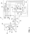
- FIG. 1 is a circuit diagram showing an overview of the configuration of an air conditioner 10.
- solid lines interconnecting devices represent refrigerant pipes
- dashed lines interconnecting devices represent transmission lines.
- an indoor unit 20 is provided with an indoor heat exchanger 21
- an outdoor unit 30 is provided with a compressor 31, a four-port switching valve 32, an outdoor heat exchanger 33, an electrically powered valve 34, and an accumulator 35
- the indoor unit 20 and the outdoor unit 30 are connected to each other by connection pipes 12.
- Refrigerant circulates in the refrigerant circuit 14.
- a first port of the four-port switching valve 32 is connected to the discharge side of the compressor 31.
- To a second port of the four-port switching valve 32 is connected one inlet/outlet of the outdoor heat exchanger 33, to a third port is connected the accumulator 35, and to a fourth port is connected a refrigerant connection pipe 12b.
- the first port and the second port of the four-port switching valve 32 are connected to each other and the third port and the fourth port of the four-port switching valve 32 are connected to each other as indicated by the solid lines.
- the first port and the fourth port of the four-port switching valve 32 are connected to each other and the second port and the third port of the four-port switching valve 32 are connected to each other as indicated by the dashed lines.
- the other inlet/outlet of the outdoor heat exchanger 33 is connected via the electrically powered valve 34 and a refrigerant connection pipe 12a to one inlet/outlet of the indoor heat exchanger 21.
- the other inlet/outlet of the indoor heat exchanger 21 is connected via the refrigerant connection pipe 12b to the fourth port of the four-port switching valve 32.
- the suction side of the compressor 31 is connected via the accumulator 35 to the third port of the four-port switching valve 32.
- the indoor unit 20 and the outdoor unit 30 are controlled by an indoor control component 50 and an outdoor control component 60.
- the indoor control component 50 and the outdoor control component 60 are connected to each other via a communication line 12c and send data to and receive data from each other.
- the indoor control component 50 and the outdoor control component 60 are each configured to include a central processing unit (CPU), a memory, and peripheral circuits.
- the various sensors are connected to the indoor control component 50 of the indoor unit 20 and the outdoor control component 60 of the outdoor unit 30.
- the various sensors include temperature sensors 40 for measuring temperatures at different sections, a high-pressure abnormality sensing component 41 that senses high-pressure abnormality of the refrigerant discharged by the compressor 31, and a pressure sensor 42 for measuring the pressure of the refrigerant sucked in by the compressor 31.
- the high-pressure abnormality sensing component 41 is, for example, a high-pressure pressure sensor.
- an inverter motor 70 of an indoor fan 22 is connected to the indoor control component 50.
- an inverter motor 80 of the compressor 31 the four-port switching valve 32, the electrically powered valve 34, and an inverter motor 90 of an outdoor fan 37 are connected to the outdoor control component 60.
- the indoor control component 50 controls the rotational speed and the operation/stopping of the inverter motor 70.
- the outdoor control component 60 controls the motor speed and the operation/stopping of the inverter motor 80 of the compressor 31 and the inverter motor 90 of the outdoor fan 37, the switching of the four-port switching valve 32, and the opening degree of the electrically powered valve 34.
- the inverter motors 70, 80, and 90 and the indoor fan 22, the compressor 31, and the outdoor fan 37 that include those inverter motors are actuators that actuate the air conditioner 10.
- actuators provided in the air conditioner 10 and inverter drivers that drive inverters for supplying alternating-current voltage to those actuators will be described taking the compressor 31 and the inverter motor 80 as an example.
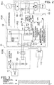
- FIG. 2 is a circuit diagram showing the connection relationship between the outdoor control component 60 and the compressor 31. It will be noted that the circuit diagram shown in FIG. 2 shows a state when the outdoor unit 30 is in operation and an abnormality is not being sensed.
- the outdoor control component 60 includes an inverter board PCB1 and a control board PCB2.
- the inverter 61 is mounted on the inverter board PCB1 .
- the inverter 61 is connected to the compressor 31, and alternating-current voltage is supplied from the inverter 61 to the compressor 31.
- the inverter 61 uses pulse width modulation (PWM) control to convert direct-current voltage output from a later-described filter circuit 69 to alternating-current voltage.
- PWM pulse width modulation
- the inverter driver 62 is equipped with a rectifier circuit 68 and a filter circuit 69.
- the rectifier circuit 68 is connected to a commercial power supply PS1.
- the rectifier circuit 68 rectifies alternating-current voltage supplied from the commercial power supply PS1 to direct-current voltage.
- the filter circuit 69 is connected to the rectifier circuit 68.
- the filter circuit 69 includes a reactor L1 and a capacitor C1 and performs noise filtering such as controlling harmonic current with the inductance of the reactor L1 and smoothing the ripple component of the direct-current voltage output from the rectifier circuit 68 with the capacitance of the capacitor C1.
- the inverter 61 is connected to the filter circuit 69.
- the inverter driver 62 performs PWM control with respect to the inverter 61.
- the inverter driver 62 is equipped with a PWM drive circuit 65.
- the PWM drive circuit 65 is a circuit for driving the inverter 61 and sends a gate signal GS to the inverter 61.
- the gate signal GS is a drive signal for driving the inverter 61.
- a voltage V1 (e.g., DC 15 V) is supplied to the inverter driver 62 from an inverter drive power supply PS2 for driving the PWM drive circuit 65.
- the inverter driver 62 is equipped with a first mechanical relay RY1 for cutting off the inverter drive power supply PS2 from the PWM drive circuit 65.
- a common contact CP1 of the first mechanical relay RY1 is connected to the inverter drive power supply PS2
- the PWM drive circuit 65 is connected to a break contact CP2 ("A contact" in FIG. 10 ) of the first mechanical relay RY1
- an abnormality notification signal transmission circuit 66 is connected to a make contact CP3 ("B contact" in FIG. 10 ) of the first mechanical relay RY1.
- the inverter driver 62 is equipped with a central processing unit (CPU) 63, the abnormality notification signal transmission circuit 66, and an emergency stop information sensing circuit 67, and an inverter control voltage V2 (e.g., DC 15 V) is supplied from an inverter control power supply PS3 to the CPU 63.
- the CPU 63 transmits to the PWM drive circuit 65 a PWM signal PWMS that applies information needed for the PWM drive circuit 65 to generate the gate signal GS.
- the abnormality notification signal transmission circuit 66 transmits a abnormal high-pressure sensing signal HPSS to the CPU 63 when the make contact CP3 is on and the voltage V1 is applied from the inverter drive power supply PS2 to the abnormality notification signal transmission circuit 66.
- the CPU 63 that has received the abnormal high-pressure sensing signal HPSS stops the PWM drive circuit 65. Furthermore, the emergency stop information sensing circuit 67 senses information instructing an emergency stop and applied from the outside of the inverter driver 62. When the emergency stop information sensing circuit 67 senses information instructing an emergency stop, it transmits an emergency stop signal ESS to the CPU 63. The CPU 63 that has received the emergency stop signal ESS stops the PWM drive circuit 65.
- the inverter control power supply PS3 is supplied to the inverter board PCB1 independently of the inverter drive power supply PS2, so that even if the inverter control power supply PS2 is cut off by the first mechanical relay RY1, the state in which the inverter control power supply PS3 is supplied to the CPU 63 is maintained.
- the inverter driver 62 is equipped with a first connection port X1A and a second connection port X2A that are connected in series to each other.
- the first connection port X1A and the second connection point X2A are break contacts.
- the first mechanical relay RY1 has a coil to which the voltage V1 is applied from the inverter drive power supply PS2 via the first connection port X1A and the second connection port X2A.
- the common contact CP1 and the break contact CP2 are connected to each other.
- the common contact CP1 and the make contact CP3 are connected to each other.
- An emergency stop circuit 110 is connected to the second connection port X2A.
- a button switch 111 for example, is provided in the emergency stop circuit 110, and the button switch 111 is configured to be pressed when the user judges that an emergency stop is necessary.
- the button switch 111 opens and the second connection port X2A also opens.
- the emergency stop circuit 110 sends to the emergency stop information sensing circuit 67 information instructing an emergency stop.
- a voltage V3 (e.g., DC 15 V) is supplied from a control board power supply PS4 to the control board PCB2.
- a control board power supply PS4 to the control board PCB2.
- a third connection port X3A is mounted on the control board PCB2 and a fourth connection port X4A.
- the voltage V3 is applied via the third connection port X3A to a coil of the second mechanical relay RY2.
- a break contact of the second mechanical relay RY2 becomes connected while current flows in the coil of the second mechanical relay RY2.
- the third connection port X3A is connected to the high-pressure abnormality sensing component 41.
- the high-pressure abnormality sensing component 41 connected to the third connection port X3A senses a high-pressure abnormality
- the high-pressure abnormality sensing component 41 switches off and the supply of the voltage V3 to the coil of the second mechanical relay RY2 is cut off.
- the break contact of the second mechanical relay RY2 is connected to the fourth connection port X4A, and the fourth connection port X4A is connected to the first connection port X1A.
- the connection between the second mechanical relay RY2, the fourth connection port X4A, and the first connection port X1A is a connection where the fourth connection port X4A becomes open when the second mechanical relay RY2 becomes open and where the first connection port X1A also becomes open when the fourth connection port X4A becomes open. Stated conversely, the fourth connection port X4A and the first connection port X1A both close when the second mechanical relay RY2 closes.
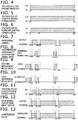
- the inverter driver 62 will be described with reference to FIG. 3 , FIG. 4, and FIG. 5 .
- the air conditioner 10 including the outdoor unit 30 until the point in time at time t1, the commercial power supply PS1 is off, so power is not supplied to the control board PCB2 or the inverter board PCB1, operation is stopped, and the voltage V1 of the inverter drive power supply PS2, the inverter control voltage V2 of the inverter control power supply PS3, and the voltage V3 of the control board power supply PS4 are all 0 V.
- the CPU 63, the PWM drive circuit 65, the abnormality notification signal transmission circuit 66, and the emergency stop information sensing circuit 67 do not work.
- the common contact CP1 and the make contact CP3 of the first mechanical relay RY1 are connected to each other and the second mechanical relay RY2 is open.
- Devices made of semiconductors such as the CPU 63 and the abnormality notification signal transmission circuit 66, generally have a faster rate of rise compared to devices that need to work mechanically, such as the first mechanical relay RY1. If the CPU 63 and the abnormality notification signal transmission circuit 66 start working quicker, there is the potential for a glitch such as a malfunction to occur. For example, if the abnormality notification signal transmission circuit 66 starts working in a state in which the common contact CP1 and the make contact CP3 of the first mechanical relay RY1 are connected to each other, there is the potential for the abnormal high-pressure sensing signal HPSS to end up being transmitted from the abnormality notification signal transmission circuit 66.
- the CPU 63 starts working in a state in which the common contact CP1 and the make contact CP3 of the first mechanical relay RY1 are connected to each other, there is the potential for the CPU 63 to end up outputting the PWM signal PWMS to the PWM drive circuit 65 which is stopped because the voltage V1 is not yet being applied from the inverter drive power supply PS2 to the PWM drive circuit 65. If the PWM signal PWMS is partially missing in this way, there are cases where trouble arises in the driving of the inverter motor 80 of the compressor 31.
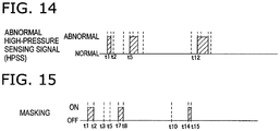
- the CPU 63 is equipped with a masking function that suspends control for a predetermined certain period from when the inverter control voltage V2 is supplied from the inverter control power supply PS3. As shown in FIG. 15 , the CPU 63 stays in a standby state without performing control for a certain period (t2 - t1) from time t1 to time t2.
- the state is always the one shown in FIG. 2 .
- the PWM signal PWMS is transmitted from the CPU 63 to the PWM drive circuit 65 at the timing of time t2
- the gate signal GS is transmitted from the PWM drive circuit 65 to the inverter 61.
- alternating-current voltage is supplied from the inverter 61 to the inverter motor 80 of the compressor 31, and operation of the compressor 31 is started.
- the working from when the high-pressure abnormality notification signal HPS is transmitted at time t3 to until the operation of the compressor 31 is stopped is working when the compressor 31 stops because of the first mechanical relay RY1.
- the second mechanical relay RY2 becomes open, and at time t5 a little later the first mechanical relay RY1 switches from the break contact CP2 (A contact) to the make contact CP3 (B contact).
- the voltage V1 of the inverter drive power supply PS2 becomes 0 V at the same time as the switching of the first mechanical relay RY1.
- the transmission of the gate signal GS from the PWM drive circuit 65 is stopped as shown in FIG. 12 and the operation of the compressor 31 is stopped as shown in FIG. 13 .
- the second mechanical relay RY2 closes a little after the cancellation of the high-pressure abnormality notification signal HPS.
- the fourth connection port X4A and the first connection port X1A close and the first mechanical relay RY1 switches from B contact to A contact.
- the voltage V1 is applied to the PWM drive circuit 65, and output of the gate signal GS from the PWM drive circuit 65 becomes possible.
- the CPU 63 performs masking from the abnormality notification signal transmission circuit 66 considering the lag time between from the cancellation of the high-pressure abnormality notification signal HPS and to until the voltage V1 is applied to the PWM drive circuit 65, and the CPU 63 starts the transmission of the PWM signal PWMS from the CPU 63 to the PWM drive circuit 65 from time t8 a little after the output of the abnormality notification signal from the abnormality notification signal transmission circuit 66 stops.
- the transmission of the gate signal GS from the PWM drive circuit 65 is started, and the application of the alternating-current voltage by the inverter 61 and the operation of the compressor 31 are resumed.
- the working from when the high-pressure abnormality notification signal HPS is transmitted from the high-pressure abnormality sensing component 41 at time t10 to until the operation of the compressor 31 is stopped is working when the compressor 31 is stopped because of the CPU 63.
- the second mechanical relay RY2 opens, and at time t12 a little later the first mechanical relay RY1 switches from the break contact CP2 (A contact) to the make contact CP3 (B contact).
- the abnormal high-pressure sensing signal HPSS is transmitted from the abnormality notification signal transmission circuit 66 to the CPU 63 as shown in FIG. 14 .
- the transmission of the PWM signal PWMS from the CPU 63 is stopped as shown in FIG.
- the high-pressure abnormality is eliminated a little after time 13 and the high-pressure abnormality notification signal HPS from the high-pressure abnormality sensing component 41 is cancelled.
- the second mechanical relay RY2 closes a little after the cancellation of the high-pressure abnormality notification signal.
- the fourth connection port X4A and the first connection port X1A close and the first mechanical relay RY1 switches from B contact to A contact.
- the voltage V1 is applied to the PWM drive circuit 65, and output of the gate signal GS from the PWM drive circuit 65 becomes possible.
- the CPU 63 performs masking from the abnormality notification signal transmission circuit 66 considering the lag time from the cancellation of the high-pressure abnormality notification signal HPS to until the voltage V1 is applied to the PWM drive circuit 65, and the CPU 63 starts the transmission of the PWM signal PWMS from the CPU 63 to the PWM drive circuit 65 from time t15 a little after the output of the abnormality notification signal from the abnormality notification signal transmission circuit 66 stops.
- the transmission of the gate signal GS from the PWM drive circuit 65 is started, and the application of the alternating-current voltage by the inverter 61 and the operation of the compressor 31 are resumed.
- the inverter drive power supply PS2 of the PWM drive circuit 65 is cut off by the first mechanical relay RY1 when a high-pressure abnormality has been detected in the high-pressure abnormality sensing component 41 in the air conditioner 10 and stopping the driving of the compressor 31 has been requested.
- the inverter motor 80 and the compressor 31 having the built-in inverter motor 80 are actuators.
- the inverter drive power supply PS2 is cut off in this way, and the contacts switch to a mechanically unconnected state because the contacts are mechanically opened and closed inside the first mechanical relay RY1.
- the drive signal with respect to the inverter 61 is certainly changed as a result of the contacts becoming mechanically opened inside the first mechanical relay RY1, and the inverter 61 that had been driven is certainly stopped.
- the driving of the inverter 61 can be certainly stopped and the certainty with which the driving of the compressor 31 is stopped is improved. Furthermore, even if a glitch occurs, such as the first mechanical relay RY1 not working because of a line break, for example, safety is maintained because the first mechanical relay RY1 maintains the state in which the common contact CP1 is connected to the make contact CP3.
- inverter motor 80 of the compressor 31 was taken as an example and described, the invention of this application can also be applied to the inverter motor 70 of the indoor fan 22 and/or the inverter motor 90 of the outdoor fan 37, and in that case also the same effects are achieved.
- the first mechanical relay RY1 is configured to include the common contact CP1 connected to the inverter drive power supply PS2 of the PWM drive circuit 65, the break contact CP2 connected to the PWM drive circuit 65, and the make contact CP3 connected to the abnormality notification signal transmission circuit 66.
- the first mechanical relay RY1 is configured in this way, disconnection of the inverter drive power supply PS2 from the PWM drive circuit 65 and notification of an abnormality by application of the voltage V1 to the abnormality notification signal transmission circuit 66 can be performed together with one action of the first mechanical relay RY1, so abnormality sensing can be swiftly and certainly performed, and the CPU 63 (an example of a microcomputer) can be reduced from erroneously sensing an abnormality other than an abnormality involving the first mechanical relay RY1. Because of the above configuration, the inverter driver 62 with which the stopping of the inverter drive power supply PS2 of the PWM drive circuit 65 and abnormality sensing can be swiftly and certainly performed can be inexpensively provided.
- the high-pressure abnormality sensing component 41 capable of outputting a request to stop the driving of the inverter motor 80 of the compressor 31 is connected via the control board PCB2 to the first connection port V1A as a device one wants to have output a request to stop the driving of an actuator.
- the first mechanical relay RY1 can work in such a way that ordinarily the first connection port X1A is closed by the high-pressure abnormality sensing component 41 and when an abnormality has been detected the first connection port X1A is opened and switched to an open state by the high-pressure abnormality sensing component 41 to disconnect the inverter drive power supply PS2 of the PWM drive circuit 65.
- a device such as the high-pressure abnormality sensing component 41 that senses an abnormality in the air conditioner 10 in this way and requests the stopping of the driving of the actuator can be easily connected using the first connection port X1A.
- the first mechanical relay RY1 is attached to the inverter board PCB1.
- the inverter board PCB 1 is a first board.
- the second mechanical relay RY2 is attached to the control board PCB2 that is separate from the inverter board PCB 1.
- the control board PCB2 is a second board. Because it has this kind of configuration, the control board PCB2 can be provided in a place where the inverter board PCB 1 is not provided.
- the control board PCB2 can be disposed on the front side of the outdoor unit 30 and the inverter board PCB1 can be disposed on the back side of the outdoor unit 30 so that it is easy to perform maintenance and settings of the air conditioner 10.
- the control board PCB2 and the inverter board PCB 1 can be partitioned from each other by a partition plate (not shown in the drawings) so that during maintenance and setting work the worker does not touch the inverter board PCB 1. That is to say, the first board and the second board can be configured so that if the first board is provided in a closed-off space, the second board can be provided in an openable space, and connection of the second mechanical relay RY2 and the high-pressure abnormality sensing component 41 can be easily carried out.
- the high-pressure abnormality sensing component 41 that is a device one wants to have output a request to stop the driving of the actuator is provided in a place where it is easy to connect-for example, if the control board PCB2 is disposed on the front side when the compressor 31 is disposed on the front side of a machine compartment-connection of the second mechanical relay RY2 and the high-pressure abnormality sensing component 41 can be easily carried out. In this way, connection of the first mechanical relay RY1 and the high-pressure abnormality sensing component 41 that is a device that requests the stopping of the driving of the actuator when an abnormality in the air conditioner 10 has been sensed becomes easy through the intervention of the first connection port X1A and the second mechanical relay RY2.
- the second connection port X2A is connected in series to the first connection port X1A and the first mechanical relay RY1. Because of this configuration, the line including the first connection port X1A and the first mechanical relay RY1 can be opened by the second connection port X2A even if the first connection port X1A is not opened, and because of the emergency stop circuit 110 the first mechanical relay RY1 can certainly change the gate signal GS with respect to the inverter 61 to certainly stop the inverter that had been driven. As a result, the certainty with which the driving of the inverter motor 80 of the compressor 31 is stopped by the emergency stop circuit 110 is improved. It will be noted that the gate signal GS is a drive signal output from the drive circuit to the inverter.
- Masking is performed by the CPU 63 when the inverter driver 62 is powered on, so even when the CPU 63 quickly switches to a working state, a glitch where the CPU 63 tries to cause the gate signal GS to be output from the PWM drive circuit 65 while the disconnection of the PWM drive circuit 65 by the first mechanical relay RY1 is not cancelled can be avoided. As a result, the occurrence of glitches at the time of the startup of the air conditioner 10 caused by using the first mechanical relay RY1 that is slow to work is prevented.
- the first mechanical relay RY1 may also be disposed between the PWM drive circuit 65 and the inverter 61 and configured to be capable of cutting off the gate signal GS that is a drive signal when a high-pressure abnormality has been detected in the high-pressure abnormality sensing component 41 in the air conditioner 10 and stopping the driving of the inverter motor 80 of the compressor 31 that is an actuator has been requested.
- the inverter driver 62 is configured to be capable of cutting off the gate signal GS that is a drive signal
- the inverter drive power supply PS2 and the inverter control power supply PS3 can also be commonalized.
- the commercial power supply PS1 is a three-phase alternating current
- the commercial power supply is not limited to a three-phase alternating current.
- the commercial power supply may also be a two-phase alternating current.
Landscapes
- Engineering & Computer Science (AREA)
- Mechanical Engineering (AREA)
- General Engineering & Computer Science (AREA)
- Chemical & Material Sciences (AREA)
- Combustion & Propulsion (AREA)
- Power Engineering (AREA)
- Physics & Mathematics (AREA)
- Thermal Sciences (AREA)
- Air Conditioning Control Device (AREA)
- Control Of Electric Motors In General (AREA)
- Control Of Ac Motors In General (AREA)
- Inverter Devices (AREA)
Applications Claiming Priority (2)
| Application Number | Priority Date | Filing Date | Title |
|---|---|---|---|
| JP2015083923A JP6464903B2 (ja) | 2015-04-16 | 2015-04-16 | 空気調和機のインバータ駆動装置 |
| PCT/JP2016/059883 WO2016167111A1 (fr) | 2015-04-16 | 2016-03-28 | Dispositif de commande d'un convertisseur de conditionneur d'air |
Publications (2)
| Publication Number | Publication Date |
|---|---|
| EP3285387A1 true EP3285387A1 (fr) | 2018-02-21 |
| EP3285387A4 EP3285387A4 (fr) | 2019-01-16 |
Family
ID=57126749
Family Applications (1)
| Application Number | Title | Priority Date | Filing Date |
|---|---|---|---|
| EP16779902.2A Withdrawn EP3285387A4 (fr) | 2015-04-16 | 2016-03-28 | Dispositif de commande d'un convertisseur de conditionneur d'air |
Country Status (6)
| Country | Link |
|---|---|
| US (1) | US10619878B2 (fr) |
| EP (1) | EP3285387A4 (fr) |
| JP (1) | JP6464903B2 (fr) |
| CN (1) | CN107580750B (fr) |
| BR (1) | BR112017020784B1 (fr) |
| WO (1) | WO2016167111A1 (fr) |
Families Citing this family (11)
| Publication number | Priority date | Publication date | Assignee | Title |
|---|---|---|---|---|
| CN106871354B (zh) * | 2017-02-22 | 2019-08-02 | 海信(广东)空调有限公司 | 一种变频空调的功率控制方法及系统 |
| JP2018161190A (ja) * | 2017-03-24 | 2018-10-18 | 東芝ライフスタイル株式会社 | 洗濯機 |
| JP6485520B1 (ja) | 2017-11-06 | 2019-03-20 | ダイキン工業株式会社 | 電力変換装置及び空気調和装置 |
| JP6851331B2 (ja) * | 2018-01-11 | 2021-03-31 | ダイキン工業株式会社 | 電力変換装置及び空気調和装置 |
| CN108679799A (zh) * | 2018-03-07 | 2018-10-19 | 南京天加环境科技有限公司 | 一种螺杆压缩机组的能量调节方法 |
| US11781776B2 (en) * | 2018-04-18 | 2023-10-10 | Mitsubishi Electric Corporation | Control substrate and indoor equipment of air conditioner |
| WO2020188764A1 (fr) * | 2019-03-19 | 2020-09-24 | 三菱電機株式会社 | Dispositif de commande d'entraînement de moteur et unité extérieure de climatiseur |
| CN111005862B (zh) * | 2019-12-16 | 2022-02-15 | 广东美的暖通设备有限公司 | 压力保护电路、控制方法和计算机可读存储介质 |
| BE1028230B1 (de) * | 2020-04-22 | 2021-12-03 | Phoenix Contact Gmbh & Co | Energieversorgungsvorrichtung mit sicherheitsgerichteter Abschaltung sowie Verfahren zum Abschalten einer Energieversorgungsvorrichtung |
| US20240128917A1 (en) * | 2021-05-11 | 2024-04-18 | Mitsubishi Electric Corporation | Motor drive device and outdoor unit of air-conditioning apparatus, which includes the same |
| CN113325766B (zh) * | 2021-05-26 | 2023-05-30 | 珠海格力电器股份有限公司 | 一种驱动控制芯片、暖通设备 |
Family Cites Families (21)
| Publication number | Priority date | Publication date | Assignee | Title |
|---|---|---|---|---|
| JPS58163272A (ja) * | 1982-03-19 | 1983-09-28 | Sanyo Electric Co Ltd | インバ−タ装置 |
| JP2865382B2 (ja) * | 1990-05-29 | 1999-03-08 | 三洋電機株式会社 | 空気調和機の制御装置 |
| JPH08149833A (ja) * | 1994-11-18 | 1996-06-07 | Sanyo Electric Co Ltd | 太陽電池発電装置の制御用電源回路及び保護回路 |
| JP4151188B2 (ja) | 2000-02-29 | 2008-09-17 | 松下電器産業株式会社 | マルチタイプ空気調和機の制御装置 |
| JP4738129B2 (ja) * | 2005-10-12 | 2011-08-03 | 三洋電機株式会社 | 空気調和装置 |
| JP4075951B2 (ja) * | 2006-03-08 | 2008-04-16 | ダイキン工業株式会社 | 負荷駆動装置及び空気調和機の室外機並びに負荷の駆動方法 |
| JP4155307B2 (ja) * | 2006-03-29 | 2008-09-24 | ダイキン工業株式会社 | 空気調和装置の制御装置 |
| JP4650477B2 (ja) * | 2007-10-30 | 2011-03-16 | ダイキン工業株式会社 | 漏電検出方法 |
| JP5289086B2 (ja) * | 2009-02-06 | 2013-09-11 | 三菱電機株式会社 | 冷凍サイクル装置 |
| KR101270336B1 (ko) * | 2009-04-17 | 2013-05-31 | 다이킨 고교 가부시키가이샤 | 전원 회로, 및 전원 회로의 제어 프로그램을 기억한 컴퓨터 판독 가능한 기억 매체 |
| JP5251950B2 (ja) * | 2010-09-27 | 2013-07-31 | ダイキン工業株式会社 | 冷凍装置のインバータ基板 |
| JP5454596B2 (ja) * | 2012-02-08 | 2014-03-26 | ダイキン工業株式会社 | 電源制御装置 |
| WO2014010225A1 (fr) * | 2012-07-09 | 2014-01-16 | パナソニック株式会社 | Dispositif de commande de compresseur électrique étanche à l'air, dispositif de compression électrique étanche à l'air, et appareil électroménager comprenant un dispositif de commande de compresseur électrique étanche à l'air et un dispositif de compression électrique étanche à l'air |
| WO2015145528A1 (fr) * | 2014-03-24 | 2015-10-01 | 三菱電機株式会社 | Système de conditionnement d'air et dispositif de relais de transmission associé |
| US10371403B2 (en) * | 2014-06-20 | 2019-08-06 | Hitachi-Johnson Controls Air Conditioning, Inc. | Display device, method, and program |
| JP6281430B2 (ja) * | 2014-07-15 | 2018-02-21 | トヨタ自動車株式会社 | 電動機制御装置 |
| JP6359423B2 (ja) * | 2014-10-24 | 2018-07-18 | 三菱重工業株式会社 | 空調システムの制御装置、空調システム、及び空調システムの制御装置の異常判定方法 |
| JP2016084969A (ja) * | 2014-10-24 | 2016-05-19 | 三菱重工業株式会社 | 空調システムの制御装置、空調システム、及び空調システムの異常判定方法 |
| US9689582B2 (en) * | 2015-04-10 | 2017-06-27 | Lennox Industries Inc. | Overvoltage recovery circuit and a controller and HVAC system including the same |
| US10158312B2 (en) * | 2016-01-20 | 2018-12-18 | Toyota Jidosha Kabushiki Kaisha | Motor control apparatus |
| JP6285475B2 (ja) * | 2016-01-29 | 2018-02-28 | ファナック株式会社 | 放電機能を有するモータ駆動装置 |
-
2015
- 2015-04-16 JP JP2015083923A patent/JP6464903B2/ja active Active
-
2016
- 2016-03-28 EP EP16779902.2A patent/EP3285387A4/fr not_active Withdrawn
- 2016-03-28 CN CN201680021692.5A patent/CN107580750B/zh active Active
- 2016-03-28 WO PCT/JP2016/059883 patent/WO2016167111A1/fr not_active Ceased
- 2016-03-28 US US15/565,632 patent/US10619878B2/en active Active
- 2016-03-28 BR BR112017020784-2A patent/BR112017020784B1/pt active IP Right Grant
Also Published As
| Publication number | Publication date |
|---|---|
| WO2016167111A1 (fr) | 2016-10-20 |
| CN107580750A (zh) | 2018-01-12 |
| BR112017020784A2 (pt) | 2018-06-26 |
| EP3285387A4 (fr) | 2019-01-16 |
| JP2016208575A (ja) | 2016-12-08 |
| US20180073765A1 (en) | 2018-03-15 |
| CN107580750B (zh) | 2020-05-08 |
| JP6464903B2 (ja) | 2019-02-06 |
| US10619878B2 (en) | 2020-04-14 |
| BR112017020784B1 (pt) | 2023-05-09 |
Similar Documents
| Publication | Publication Date | Title |
|---|---|---|
| EP3285387A1 (fr) | Dispositif de commande d'un convertisseur de conditionneur d'air | |
| AU2010238133B2 (en) | Power circuit, and computer-readable recording medium storing a control program for power circuits | |
| CN101197532B (zh) | 冷冻装置及用于冷冻装置的逆变装置 | |
| CN104764174B (zh) | 空气调节装置 | |
| KR20140096179A (ko) | 공기조화장치 | |
| JP2000111123A (ja) | セパレート形空気調和機 | |
| JP6797311B2 (ja) | 空気調和機 | |
| JP5289086B2 (ja) | 冷凍サイクル装置 | |
| JP5582989B2 (ja) | 空気調和装置 | |
| WO2019021397A1 (fr) | Climatiseur | |
| CN108307651B (zh) | 空气调节装置 | |
| JP2012159270A (ja) | 制御装置及びヒートポンプ装置 | |
| EP3443226B1 (fr) | Dispositif de commande pour compresseur | |
| JP5381140B2 (ja) | トレーラー用冷凍装置 | |
| KR102478858B1 (ko) | 공기조화기(air conditioner) | |
| JP5804009B2 (ja) | 空気調和装置 | |
| JP7051355B2 (ja) | 空気調和機 | |
| JP4623220B2 (ja) | 電源回路 | |
| JP2016169884A (ja) | 空気調和機のモータ駆動装置 | |
| JP5417740B2 (ja) | インバータ装置 | |
| CN113544438B (zh) | 空调机的室外机以及空调系统 | |
| JP2020048320A (ja) | 冷凍サイクル装置 | |
| JP2012047367A (ja) | 空気調和機 | |
| JP2016169883A (ja) | 空気調和機のモータ駆動装置 | |
| CN111525494B (zh) | 驱动控制电路、控制方法、装置、压缩机、空调器和介质 |
Legal Events
| Date | Code | Title | Description |
|---|---|---|---|
| STAA | Information on the status of an ep patent application or granted ep patent |
Free format text: STATUS: THE INTERNATIONAL PUBLICATION HAS BEEN MADE |
|
| PUAI | Public reference made under article 153(3) epc to a published international application that has entered the european phase |
Free format text: ORIGINAL CODE: 0009012 |
|
| STAA | Information on the status of an ep patent application or granted ep patent |
Free format text: STATUS: REQUEST FOR EXAMINATION WAS MADE |
|
| 17P | Request for examination filed |
Effective date: 20171114 |
|
| AK | Designated contracting states |
Kind code of ref document: A1 Designated state(s): AL AT BE BG CH CY CZ DE DK EE ES FI FR GB GR HR HU IE IS IT LI LT LU LV MC MK MT NL NO PL PT RO RS SE SI SK SM TR |
|
| AX | Request for extension of the european patent |
Extension state: BA ME |
|
| DAV | Request for validation of the european patent (deleted) | ||
| DAX | Request for extension of the european patent (deleted) | ||
| RIC1 | Information provided on ipc code assigned before grant |
Ipc: H02P 27/08 20060101ALI20161025BHEP Ipc: H02P 29/024 20160101ALI20161025BHEP Ipc: H02M 7/48 20070101AFI20161025BHEP Ipc: F24F 11/02 20181130ALI20161025BHEP |
|
| A4 | Supplementary search report drawn up and despatched |
Effective date: 20181217 |
|
| RIC1 | Information provided on ipc code assigned before grant |
Ipc: H02M 7/48 20070101AFI20181211BHEP Ipc: H02P 29/024 20160101ALI20181211BHEP Ipc: H02P 27/08 20060101ALI20181211BHEP |
|
| RIC1 | Information provided on ipc code assigned before grant |
Ipc: H02P 27/08 20060101ALI20181211BHEP Ipc: H02M 7/48 20070101AFI20181211BHEP Ipc: H02P 29/024 20160101ALI20181211BHEP |
|
| STAA | Information on the status of an ep patent application or granted ep patent |
Free format text: STATUS: EXAMINATION IS IN PROGRESS |
|
| 17Q | First examination report despatched |
Effective date: 20210604 |
|
| RAP3 | Party data changed (applicant data changed or rights of an application transferred) |
Owner name: DAIKIN INDUSTRIES, LTD. |
|
| P01 | Opt-out of the competence of the unified patent court (upc) registered |
Effective date: 20230525 |
|
| REG | Reference to a national code |
Ref country code: DE Ref legal event code: R079 Free format text: PREVIOUS MAIN CLASS: H02M0007480000 Ipc: H02M0001000000 |
|
| GRAP | Despatch of communication of intention to grant a patent |
Free format text: ORIGINAL CODE: EPIDOSNIGR1 |
|
| STAA | Information on the status of an ep patent application or granted ep patent |
Free format text: STATUS: GRANT OF PATENT IS INTENDED |
|
| RIC1 | Information provided on ipc code assigned before grant |
Ipc: F24F 140/10 20180101ALN20240227BHEP Ipc: H02P 27/06 20060101ALN20240227BHEP Ipc: H02M 5/458 20060101ALN20240227BHEP Ipc: F24F 11/89 20180101ALI20240227BHEP Ipc: F24F 11/86 20180101ALI20240227BHEP Ipc: F24F 11/32 20180101ALI20240227BHEP Ipc: H02P 29/024 20160101ALI20240227BHEP Ipc: H02P 27/08 20060101ALI20240227BHEP Ipc: H02P 3/18 20060101ALI20240227BHEP Ipc: H02M 7/48 20070101ALI20240227BHEP Ipc: H02M 1/32 20070101ALI20240227BHEP Ipc: H02M 1/00 20060101AFI20240227BHEP |
|
| INTG | Intention to grant announced |
Effective date: 20240318 |
|
| STAA | Information on the status of an ep patent application or granted ep patent |
Free format text: STATUS: THE APPLICATION IS DEEMED TO BE WITHDRAWN |
|
| 18D | Application deemed to be withdrawn |
Effective date: 20240719 |