EP3286115B1 - Procédé d'installation pour régler des dispositifs de convoyage - Google Patents
Procédé d'installation pour régler des dispositifs de convoyage Download PDFInfo
- Publication number
- EP3286115B1 EP3286115B1 EP16717907.6A EP16717907A EP3286115B1 EP 3286115 B1 EP3286115 B1 EP 3286115B1 EP 16717907 A EP16717907 A EP 16717907A EP 3286115 B1 EP3286115 B1 EP 3286115B1
- Authority
- EP
- European Patent Office
- Prior art keywords
- control unit
- conveyor
- rotation
- conveyor drive
- sensor
- Prior art date
- Legal status (The legal status is an assumption and is not a legal conclusion. Google has not performed a legal analysis and makes no representation as to the accuracy of the status listed.)
- Active
Links
Images




Classifications
-
- B—PERFORMING OPERATIONS; TRANSPORTING
- B65—CONVEYING; PACKING; STORING; HANDLING THIN OR FILAMENTARY MATERIAL
- B65G—TRANSPORT OR STORAGE DEVICES, e.g. CONVEYORS FOR LOADING OR TIPPING, SHOP CONVEYOR SYSTEMS OR PNEUMATIC TUBE CONVEYORS
- B65G43/00—Control devices, e.g. for safety, warning or fault-correcting
- B65G43/10—Sequence control of conveyors operating in combination
-
- B—PERFORMING OPERATIONS; TRANSPORTING
- B65—CONVEYING; PACKING; STORING; HANDLING THIN OR FILAMENTARY MATERIAL
- B65G—TRANSPORT OR STORAGE DEVICES, e.g. CONVEYORS FOR LOADING OR TIPPING, SHOP CONVEYOR SYSTEMS OR PNEUMATIC TUBE CONVEYORS
- B65G43/00—Control devices, e.g. for safety, warning or fault-correcting
-
- G—PHYSICS
- G05—CONTROLLING; REGULATING
- G05B—CONTROL OR REGULATING SYSTEMS IN GENERAL; FUNCTIONAL ELEMENTS OF SUCH SYSTEMS; MONITORING OR TESTING ARRANGEMENTS FOR SUCH SYSTEMS OR ELEMENTS
- G05B19/00—Program-control systems
- G05B19/02—Program-control systems electric
- G05B19/04—Program control other than numerical control, i.e. in sequence controllers or logic controllers
- G05B19/042—Program control other than numerical control, i.e. in sequence controllers or logic controllers using digital processors
- G05B19/0426—Programming the control sequence
-
- G—PHYSICS
- G05—CONTROLLING; REGULATING
- G05B—CONTROL OR REGULATING SYSTEMS IN GENERAL; FUNCTIONAL ELEMENTS OF SUCH SYSTEMS; MONITORING OR TESTING ARRANGEMENTS FOR SUCH SYSTEMS OR ELEMENTS
- G05B19/00—Program-control systems
- G05B19/02—Program-control systems electric
- G05B19/418—Total factory control, i.e. centrally controlling a plurality of machines, e.g. direct or distributed numerical control [DNC], flexible manufacturing systems [FMS], integrated manufacturing systems [IMS] or computer integrated manufacturing [CIM]
- G05B19/4185—Total factory control, i.e. centrally controlling a plurality of machines, e.g. direct or distributed numerical control [DNC], flexible manufacturing systems [FMS], integrated manufacturing systems [IMS] or computer integrated manufacturing [CIM] characterised by the network communication
- G05B19/4186—Total factory control, i.e. centrally controlling a plurality of machines, e.g. direct or distributed numerical control [DNC], flexible manufacturing systems [FMS], integrated manufacturing systems [IMS] or computer integrated manufacturing [CIM] characterised by the network communication by protocol, e.g. MAP, TOP
-
- G—PHYSICS
- G05—CONTROLLING; REGULATING
- G05B—CONTROL OR REGULATING SYSTEMS IN GENERAL; FUNCTIONAL ELEMENTS OF SUCH SYSTEMS; MONITORING OR TESTING ARRANGEMENTS FOR SUCH SYSTEMS OR ELEMENTS
- G05B19/00—Program-control systems
- G05B19/02—Program-control systems electric
- G05B19/418—Total factory control, i.e. centrally controlling a plurality of machines, e.g. direct or distributed numerical control [DNC], flexible manufacturing systems [FMS], integrated manufacturing systems [IMS] or computer integrated manufacturing [CIM]
- G05B19/4189—Total factory control, i.e. centrally controlling a plurality of machines, e.g. direct or distributed numerical control [DNC], flexible manufacturing systems [FMS], integrated manufacturing systems [IMS] or computer integrated manufacturing [CIM] characterised by the transport system
-
- H—ELECTRICITY
- H04—ELECTRIC COMMUNICATION TECHNIQUE
- H04L—TRANSMISSION OF DIGITAL INFORMATION, e.g. TELEGRAPHIC COMMUNICATION
- H04L61/00—Network arrangements, protocols or services for addressing or naming
- H04L61/50—Address allocation
- H04L61/5038—Address allocation for local use, e.g. in LAN or USB networks, or in a controller area network [CAN]
-
- B—PERFORMING OPERATIONS; TRANSPORTING
- B65—CONVEYING; PACKING; STORING; HANDLING THIN OR FILAMENTARY MATERIAL
- B65G—TRANSPORT OR STORAGE DEVICES, e.g. CONVEYORS FOR LOADING OR TIPPING, SHOP CONVEYOR SYSTEMS OR PNEUMATIC TUBE CONVEYORS
- B65G2203/00—Indexing code relating to control or detection of the articles or the load carriers during conveying
- B65G2203/02—Control or detection
- B65G2203/0266—Control or detection relating to the load carrier(s)
-
- G—PHYSICS
- G05—CONTROLLING; REGULATING
- G05B—CONTROL OR REGULATING SYSTEMS IN GENERAL; FUNCTIONAL ELEMENTS OF SUCH SYSTEMS; MONITORING OR TESTING ARRANGEMENTS FOR SUCH SYSTEMS OR ELEMENTS
- G05B2219/00—Program-control systems
- G05B2219/20—Pc systems
- G05B2219/23—Pc programming
- G05B2219/23193—Memory stores lifetime, different settings, configurations of controlled device
-
- G—PHYSICS
- G05—CONTROLLING; REGULATING
- G05B—CONTROL OR REGULATING SYSTEMS IN GENERAL; FUNCTIONAL ELEMENTS OF SUCH SYSTEMS; MONITORING OR TESTING ARRANGEMENTS FOR SUCH SYSTEMS OR ELEMENTS
- G05B2219/00—Program-control systems
- G05B2219/20—Pc systems
- G05B2219/25—Pc structure of the system
- G05B2219/25092—Customized control features, configuration
-
- G—PHYSICS
- G05—CONTROLLING; REGULATING
- G05B—CONTROL OR REGULATING SYSTEMS IN GENERAL; FUNCTIONAL ELEMENTS OF SUCH SYSTEMS; MONITORING OR TESTING ARRANGEMENTS FOR SUCH SYSTEMS OR ELEMENTS
- G05B2219/00—Program-control systems
- G05B2219/20—Pc systems
- G05B2219/25—Pc structure of the system
- G05B2219/25204—Translate between different communication protocols
-
- G—PHYSICS
- G05—CONTROLLING; REGULATING
- G05B—CONTROL OR REGULATING SYSTEMS IN GENERAL; FUNCTIONAL ELEMENTS OF SUCH SYSTEMS; MONITORING OR TESTING ARRANGEMENTS FOR SUCH SYSTEMS OR ELEMENTS
- G05B2219/00—Program-control systems
- G05B2219/20—Pc systems
- G05B2219/26—Pc applications
- G05B2219/2621—Conveyor, transfert line
Definitions
- the invention relates to an installation method for setting up a control unit in a conveyor device, a first control unit controlling an upstream first conveyor segment and a second control unit controlling a downstream second conveyor segment.
- the first conveyor segment here comprises a first conveyor drive for conveying an object through the first conveyor segment and a first sensor unit for detecting an object at a position within the first conveyor segment.
- the first conveyor drive and the first sensor unit are coupled to the first control unit in terms of signaling in order to control the first conveyor drive and to receive a first sensor signal from the first sensor unit.
- the structure of the second conveyor segment is analogous to the first conveyor segment with regard to the features mentioned above.
- Conveyor devices are used in conveyor systems in which logistics processes run fully and partially automatically. For example, packages, pallets, goods and other goods are transported from an origin to a destination by means of conveying devices. Starting points and destinations are in complex conveyor systems sometimes far apart. Larger conveying devices are therefore subdivided into a plurality of conveying segments which are arranged in series one behind the other and thus form a conveying path which conveys a transport good from the starting point downstream to the destination. Conveyor lines can be set up in parallel and z. B. be connected to one another by merging devices, separating devices, lowering devices or lifting devices. This results in complex conveyor devices that consist of a large number of conveyor segments. In principle, each conveyor segment can have a separate control unit arranged in a housing, or the control units for several adjacent conveyor segments can be combined in a common control module.
- a conveyor segment is also equipped with a sensor unit which provides information in the form of an occupancy signal as to whether a conveyor segment is occupied by a transport item or whether it is unoccupied.
- typical sensors are, for example, light barriers, light sensors, optical scanners or proximity switches. This information is required during the operation of a conveyor system for monitoring and planning the transport flow.
- Each conveyor segment has a conveyor drive, for. B. roller drives, belt drives, vibration drives and others.
- each conveyor segment is signal-connected to a control unit.
- a central control takes over the control of the conveying process within the conveying device or a section of the conveying device.
- the central control device sends commands to individual control units via bus communication.
- This typically includes commands for activating and deactivating a conveyor drive, parameter specifications for the speed of a conveyor drive and the like.
- the central control device in turn receives signals from the control units, for example an occupied signal, by means of bus communication.
- the entire logical handling of the conveying process takes place in the central control device; the individual control units only serve to implement commands and sensor signals.
- a decentralized control method is also known.
- the logical handling of the conveying process is moved to the individual control units.
- the control units exchange signals with one another; for example, neighboring control units can be made aware of the occupancy or capacity of at least their downstream neighboring conveyor segment.
- a control unit activates the conveyor drive connected to it in order to transport the objects over the conveyor line without collision US 2012/0175223 A1 and US 2012/0175225
- a conveying device is known in which the control units are connected to one another with a peer-to-peer signal connection.
- a control unit is designed to communicate with downstream and upstream peer-to-peer-connected control units of assigned conveyor zones.
- WO0203153A2 discloses a method for automatically configuring a plurality of components performing a common process in which an event is triggered in the process and each component sends an acknowledgment of receipt when it registers this event and generates a send message when the event ends for the component is.
- the method can be used to identify upstream and downstream components.
- hybrid control methods consisting of centralized and decentralized control methods can also be implemented in which parts of the logic are arranged centrally and parts of the logic are arranged decentrally.
- each conveyor segment must be configured individually when installing a new conveyor device. This is associated with a considerable expenditure of work and time, since it requires a large number of parameters to be set in order to configure the control units.
- the establishment of complex conveyor systems also requires qualified specialist staff.
- due to the complexity there is a high probability that individual control units will be configured incorrectly, which in turn can result in additional expenditure of time and money due to any troubleshooting.
- this object is achieved by a method according to claim 1.
- a control unit is to be understood as an electronic circuit that controls and monitors a conveyor segment.
- a control unit can also control and monitor several such conveyor segments.
- a sensor signal is to be understood as a signal value that is generated by a sensor unit and represents the presence or absence of an object within a conveying segment. Any component that can generate such a signal is suitable as a sensor unit, e.g. B. a light barrier, a light button or a proximity switch.
- An installation parameter should be understood to mean at least one data value that can be stored in a control unit and contains information that is required when setting up the conveying device or is determined during this setting. This can mean, for example, individual bus addresses, parameters for configuring the conveyor drives or parameters for configuring a control unit.
- a triggering of the sensor signal can be understood to mean a change in the signal value at the output of a sensor unit, which preferably has a rising or falling signal edge.
- the absence of the sensor signal should be understood to mean the absence of a change in the signal value at the output of a sensor unit, e.g. B. the absence of a rising or falling signal edge.
- the method according to the invention enables a systematic and at the same time automatic setting up of conveyor devices, the method being equally suitable for putting a newly installed conveyor system into operation or to configure an existing and modified, for example expanded or reduced system.
- an object is placed on the first conveyor segment of a conveyor line.
- the object can be, for example, a package, a cardboard box or a transport tray.
- any object is suitable for use in this method which does not exceed the physical dimensions of the conveyor device and preferably of a conveyor segment and can be conveyed by the conveyor device without the risk of jamming.
- the object is preferably predetermined in its dimensions and smaller than a conveyor segment.
- This learning mode provides that the control units can receive and process special commands and commands by means of bus communication.
- the learning mode is activated on the first control unit
- the first and second conveyor drives are activated by the first and second control units. This can be done simultaneously or with a time delay. In particular, this can be done by activating all conveyor drives of the conveyor device.
- the object placed on the first conveyor segment is conveyed downstream to the exit area of the conveyor segment and transported further into the entrance area of the second conveyor segment until it finally rests completely on the second conveyor segment.
- the first and second sensor signals are triggered by the object.
- an installation parameter is stored in the first or second control unit.
- the first and second control units recognize from this that they are directly adjacent to one another. Because the storage of the installation parameters is linked to the transport of the object, the setting up process of a transport device can be linked to the transport of an object. This simplifies the installation of a complex conveyor system with a large number of conveyor segments, whereby the time and cost expenditure for the installation process can be reduced. In particular, this is due to the fact that manual intervention by a user to configure all conveyor devices of a conveyor line can be limited to placing the object on the first conveyor segment and activating the learning mode, since required installation parameters are automatically saved in the control units. It is preferred that the learning mode is activated on the control unit from which the object is to be conveyed downstream.
- an advantage of the method described is that the installation method described for setting up conveyor devices can also be carried out by non-skilled persons.
- the neighborhood relationships of the conveyor segments within a conveyor line can be determined based on the sequence in which the sensor signals are triggered and are automatically recognized. Knowledge of the neighborhood relationships of conveyor segments in a conveyor line is required to operate the conveyor system.
- a transfer message containing bus address information is generated in the first control unit.
- the bus address information can contain an individual bus address or a code from which an individual bus address can be created. This individual bus address is to be assigned to a control unit so that addressing of a control unit is made possible by means of bus communication.
- This bus address information is preferably a sequence of digits, an alphanumeric sequence of characters or a sequence of letters or a combination of the sequences mentioned.
- the transfer message can contain, for example, an individual bus address that is to be assigned to the second control unit.
- the transfer message can also contain the individual bus address of the first control unit, on the basis of which an individual bus address for the second control unit is calculated in the second control unit by means of an algorithm.
- the first control unit can transmit the transfer message from the first control unit to the second control unit by means of the bus communication. This is done, for example, by periodically sending the transfer message by means of bus communication.
- the transfer of the transfer message can also be triggered by the occurrence of a predetermined condition, for example by the triggering of a sensor signal in the first or second conveyor segment.
- the second control unit can be assigned an individual bus address from the bus address information and stored in the second control unit as an installation parameter.
- the second control unit receives the handover message periodically sent out by the first control unit and processes it when the second sensor unit is activated by the object and triggers the second sensor signal. After an individual bus address has been assigned and saved, the second control unit can be addressed via the bus communication and thus configured and controlled. If there are further conveyor segments in the conveyor line, the object is conveyed further and the steps described are applied successively to further conveyor segments located downstream.
- the control units which are usually manufactured identically, do not have an individual bus address at the beginning of a device by means of which they can be addressed via the bus communication.
- This installation parameter is usually defined in a manual initial configuration of the control units of a conveyor device.
- the method according to the invention facilitates an automatic, reliable and time-efficient assignment of individual bus addresses to the control units and thus represents a preferred method for the partially automated commissioning of conveying devices.
- a downstream direction of rotation should be understood to mean a direction of rotation of the first or second conveyor drive, by means of which an object is conveyed downstream.
- the second sensor signal can be detected in the first control unit by means of bus communication.
- sensor signals from the first control unit can be read out of the second control unit by means of bus communication, or the second control unit sends the sensor signal, e.g. B. in the event of a signal change, by means of the bus communication to the first control unit. This also applies to the second control unit.
- the direction in which the object is conveyed depends on the direction of rotation of the conveyor drive, which is dependent, for example, on the installation position of the conveyor drive in the conveyor device or the polarity of the supply voltage of the conveyor drive or its wiring.
- Activating the first conveyor drive in a first direction of rotation therefore does not necessarily result in the object being conveyed in the direction of the second conveyor segment.
- the concrete implementation results in assembly positions in which the sensor unit is mounted upstream of the center of a conveyor segment or downstream of the center of a conveyor segment.
- the direction of rotation of the first conveyor drive can be recognized directly by triggering the first sensor signal.
- the direction of rotation of the first conveyor drive is recognized by the expiry of a first period of time which begins from the activation of the first conveyor drive.
- the list is not to be regarded as exhaustive. Rather, other cases can arise, such as B. by inconsistent mounting positions of the sensor units within the first and second conveyor segment or by the fact that a user places the object on the first conveyor segment in such a way that the first sensor unit is triggered when the learning mode is activated.
- the direction of rotation of the first and / or second conveyor drive is reversed due to the absence of the first and / or second sensor signal.
- This embodiment extends the detection of the direction of rotation described above. A reversal of the direction of rotation can accordingly be triggered by the absence of the first, the second or the first and second sensor signals.
- the reversal of the direction of rotation of the first and / or second conveyor drive takes place as a function of the absence of the first and / or second sensor signal within a predetermined period of time after activation of the first conveyor drive.
- This embodiment extends the detection of the direction of rotation described above. A reversal of the direction of rotation can therefore pass by a predetermined period of time if the first, the second or the first and second sensor signals are not triggered within this period of time.
- the direction of rotation of the first and / or second conveyor drive is reversed by triggering the first and / or the second sensor signal.
- This embodiment extends the detection of the direction of rotation described above. A reversal of the direction of rotation can accordingly be triggered by the occurrence of the first, the second or the first and second sensor signals.
- the reversal of the direction of rotation of the first conveyor drive is triggered on the basis of the first sensor signal and the reversal of the direction of rotation of the second conveyor drive is triggered on the basis of the second sensor signal.
- This embodiment extends the detection of the direction of rotation described above.
- the direction of rotation is reversed in particular by a sensor signal from the sensor that is assigned to a conveyor segment.
- the first sensor signal of the first conveyor segment is processed in the first control unit in order to control the first conveyor drive. This applies analogously to the second sensor signal and the second conveyor drive.
- the direction of rotation of the first conveyor drive is stored in the first control unit as the downstream direction of rotation and the direction of rotation of the second conveyor drive in the second control unit is stored as the downstream direction of rotation.
- the direction of rotation of the first conveyor drive and the direction of rotation of the second conveyor drive then represent the required directions of rotation for downstream conveyance. It is therefore preferred to store these directions of rotation.
- the direction of rotation of the first conveyor drive is stored in the first control unit and the direction of rotation of the second conveyor drive is stored in the second control unit.
- the learning mode is terminated after a predetermined number of reversals of the direction of rotation, in particular that the learning mode is terminated after four reversals of the direction of rotation.
- the detection of the direction of rotation is incorrect and unsuccessful.
- An error in the detection of the direction of rotation can be caused, for example, by the fact that the object to be transported is jammed in a conveyor segment, that it is too long and cannot be transported, or that an object was not even placed on the conveyor.
- After four reversals of the direction of rotation, for example in the first conveyor segment it can be assumed that transport of the object through the first conveyor segment is not possible.
- a continuation of the method for setting up the conveyor devices is very likely no longer successful in this case. Rather, it is preferred that the control unit, which has repeatedly reversed the direction of rotation, sends out an error message by means of the bus communication and, if necessary, leaves the learning mode.
- first and second conveyor drives preferably by activating all conveyor drives, in particular by activating all conveyor drives with the exception of the conveyor drives that are connected to a control unit in which an individual bus address has already been stored, the object is transported becomes.
- Conveyor drives from upstream control units that have already received an individual bus address are no longer required for conveying the object and can be switched off. In this way, on the one hand, energy can be saved and, on the other hand, the progress of the installation process can be followed visually by a user.
- the sequence of the conveying devices to be activated, with which a transport good is conveyed downstream can be determined by means of the neighborhood relationships.
- a central processing unit can be understood to mean a server or a PC or a dedicated processing module with specific programming.
- a neighborhood relationship should be understood to mean the spatial proximity of control units within a conveyor device.
- the central processing unit can preferably provide the determined neighborhood relationships to further systems or to a user.
- knowledge of the proximity relationship between conveyor segments and the associated control units is necessary information for calculating the transport flow within a conveyor device.
- the merging of all individual bus addresses of all control units of a conveyor line within a central processing unit enables configuration and / or monitoring of the conveyor line from this central processing unit.
- the central processing unit is executed by a PC, for example, a computer program executed on it can read out the configurations of the control units using the individual bus addresses, derive the neighborhood relationships from the bus addresses and provide them to a user on a graphical output unit.
- the graphic representation of the neighborhood relationships and the configurations of the control units can be used to call up information about the configurations of the conveyor segments of a conveyor line with little expenditure of time, but at the same time with high reliability.
- the second control unit has a first program unit, which is signal-technically coupled to the second conveyor drive and the second sensor unit of the second conveyor segment, and a second program unit, which is signal-wise to a third conveyor drive and a third sensor unit of a third conveyor segment is coupled, and that the first and second program units are signal-coupled within the second control unit, in particular that the first and second program units are signal-coupled within the control unit to a common electronic memory, and that the first and the second program unit within a control unit recognizes the direction of rotation of the second and third conveyor drive, which conveys the object downstream, according to one of claims 3-10, wherein the first or the second program unit takes the place of the first or second control unit, and the communication of the program units takes place by means of the signal coupling within the control unit.
- a program unit should be understood to mean part of an embedded software that is executed in a control unit.
- Such a program unit allows the control of a conveyor drive and the monitoring of a sensor signal of a sensor unit. This is intended in particular to enable a single control unit to control and monitor a first and a second conveyor segment by means of a first and a second program unit.
- these program units can detect the direction of rotation of a conveyor drive with the aid of sensor signals.
- the advantage of this design is that the number of control units required can be reduced.
- the program units exchange data about the sensor signals and the direction of rotation of the conveyor drives via a shared memory. This common memory is preferably integrated in the control unit.
- program units only exist within a control unit.
- control unit contains the number of program units a control unit contains is not limited.
- a control unit contains four program units for controlling and monitoring four conveyor segments. If data are to be exchanged with other control units, this is done using the embedded software of the control unit and the bus communication.
- the control unit can be encapsulated in a housing. This is relevant for applications in which a watertight, dustproof or gas-tight encapsulation of the control unit is to be achieved.
- the magnetic field-based or command-based activation of the learning mode means that the use of fault-prone mechanical contacts can be dispensed with, which increases the reliability of the control units. Furthermore, accidental activation is made more difficult by this embodiment, since either a magnetic object has to be brought into the vicinity of the control unit or a command has to be transmitted by means of the communication bus.
- Such a user interface is preferably located on a central processing unit.
- the individual bus address of the first control unit was previously specified manually by the user in the form of a sequence of digits or was defined by a preconfigured original number.
- This embodiment is advantageous because it is customary in conveyor systems to carry out structured numbering of the conveyor segments in order to facilitate orientation for operating personnel. This is advantageous, for example, when maintenance work or troubleshooting is to be carried out on individual conveyor devices. It is therefore preferred to manually assign an individual bus address to the first control unit, which is integrated into the numbering system of the conveyor system.
- a preconfigured original number can be advantageous since it enables the first control unit to be identified.
- the individual bus addresses for further control units can then be numbered consecutively, for example.
- an individual clear text name is assigned to a control unit, in particular that the first control unit is assigned a clear text name that was previously specified manually by the user in the form of a sequence of letters and / or numbers or defined by a preconfigured original clear text name has been.
- This plain text name can consist of letters and / or numbers and can preferably be used for further control units are continuously changed, the change being able to affect the sequence of letters and / or the digits.
- the plain text name can consist of a unique and easily understandable character string that contains the name of the conveyor line and is followed by a sequence of digits that consecutively number the conveyor segments.
- An original plain text name should be understood to mean a plain text name that was already assigned to a control unit by a user before it was assigned, preferably stored in a control unit before it was first used.
- a plain text name is advantageous when maintenance work and maintenance work are carried out in a conveyor device. Conveyor segments can be identified quickly and safely by plant personnel using clear text names.
- a subaddress is to be understood as an additional address space for differentiating addressing in bus communication, to which the individual bus address is subordinate. Furthermore, the subaddress does not have to be unique. For example, an identical sub-address can be assigned to a plurality of control units. As a result, a plurality of control units can be addressed simultaneously. B. can be used when activating the learning mode on other control units. With such a type of subaddress, subnets can be defined in which control units can be defined in groups, for example a group of control units of a single conveyor line, and can be addressed by means of bus communication via the subaddress.
- the subaddress of a control unit or program unit is a sequence of digits previously defined manually by the user or a preconfigured original number.
- This embodiment is advantageous because in Conveyor systems it is common to carry out a structured numbering of the conveyor segments in order to facilitate orientation for operating personnel. This is advantageous, for example, when maintenance work or troubleshooting is to be carried out on individual conveyor devices. It is therefore preferred to manually assign a subaddress to control units or program units, which is integrated into the numbering system of the conveyor system.
- a preconfigured original number can be advantageous since it can, for example, be assigned to an unconfigured control unit of a group of unconfigured control units.
- the first conveyor segment is assigned conveying parameters by storing corresponding conveying parameters in the first control unit, and preferably after the object has triggered the second sensor signal, the conveying parameters of the first control unit are saved in the second control unit will.
- Conveying parameters should be understood to mean parameters that influence the conveyance of the object and represent parameters of the conveying segment. This can be, for example, the direction of rotation, the speed of rotation, the acceleration curves or deceleration curves of the conveyor drives.
- These conveying parameters are stored in a separate parameterization step, for example by a user, in the first control unit.
- a deposit can be made via bus communication or by direct manual input on a control unit.
- Conveyor segments of a conveyor line often have the same conveying parameters. It is therefore preferred that the conveying parameters that are stored in the first control unit are transmitted to the second control unit and stored there after the second sensor signal has been triggered. This simplifies the setting up of conveyor lines accordingly, since the conveyor parameters are automatically copied into each additional control unit. It is also ensured that all conveyor segments of a conveyor line receive the same conveyor parameters.
- a visual and / or acoustic user interface is created.
- This user interface should be able to display the status of the learning mode to a user, in particular the end of the learning mode, and / or be able to signal to the user that the direction of rotation has been incorrectly recognized.
- Visual signaling can be done by optical signals that are implemented by appropriate light sources, such as light emitting diodes or flash lamps, or by a predetermined sequence of activating and deactivating a conveyor drive of a conveyor segment. This can be, for example, a sequence in which the conveyor drive is activated by the control unit for one second and deactivated for three seconds. This sequence can experience a predetermined number of repetitions or can be ended by a condition such as ending the learning mode.
- an acoustic signal signals the end of the learning mode and / or incorrect detection of the direction of rotation.
- This acoustic signal can be emitted by an electroacoustic sound transducer, which is preferably integrated and encapsulated in a control unit.
- the advantage of acoustic signaling is that no line of sight to the control unit is required.
- the aforementioned object is achieved by a device, in particular a conveying device.
- the conveyor device can be further developed in that the first or the second control unit is designed to end the learning mode after a predetermined number of reversals of the direction of rotation.
- the conveying device can be developed in that a control unit is designed to be assigned an individual plain text name, which is a sequence of letters and / or numbers, or to be assigned a preconfigured original plain text name.
- the conveying device can be developed in that a control unit is designed to be addressed via a subaddress by means of bus communication, the subaddress being a sequence of digits previously defined manually by the user or a preconfigured original number.
- a section of a conveyor device is shown, which consists of a total of three conveyor segments 100-300.
- the conveyor segments 100-200 are directly adjacent and form a conveyor line.
- the presence of the conveyor segment 300 is not mandatory.
- Each conveyor segment 100-300 contains a conveyor drive 101-301 which also drives the idle rollers of the conveyor segment via belts and thus conveys the goods 40.
- the conveying direction 105-305 is determined by the direction of rotation 106-306 of the conveyor drives 101-301 determined.
- the direction of rotation is configured in such a way that the transported goods are transported downstream.
- each conveyor segment has a control unit 102-302, each of which contains a Hall-effect sensor 104-304 for activating the learning mode.
- a sensor unit 103-303 mounted downstream of the center of the conveyor segment is connected to this control unit 102-302.
- This sensor unit is arranged in such a way that the presence of a transport item in the exit area of the individual conveyor segments can be checked.
- the conveyor drives 101-301 are also connected to the control units 103-303.
- a data exchange between the control units can take place by means of the bus communication 70.
- Fig. 1 the initial state of a setup process is shown schematically.
- a user has placed goods to be transported on the first conveyor segment 100 and by approaching a magnet (in Fig. 1 not shown) activate the learning mode on the Hall effect sensor 104.
- a command is sent via the bus communication 70 to the other conveyor segments 200 and optionally 300, whereby the control units 202 and optionally 302 are also put into learning mode.
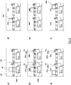
- the Fig. 2 a) represents an example of the initial situation for running through the method according to the invention.
- Two conveyor segments 100-200 are shown.
- a transport item 40 is located on the conveyor segment 100.
- the Hall sensor 104a of the first control unit is already activated by a user by stopping a magnet, which is symbolized by the closed switching contact.
- Fig. 2 c the method step is shown which takes place after a first period of time during which the first control unit has not received a signal from the first sensor unit.
- the directions of rotation of the conveyor drives are reversed by the control units and the directions of rotation 106b and 206b for the conveyor drives 101-201 result.
- the goods to be transported are conveyed in the downstream direction according to the installation.
- the sensor unit 103a of the first conveyor segment is activated, so the directions of rotation 106b and 206b of the conveyor drives are stored in the control units as the new preferred direction of rotation.
- the cargo continues to be transported downstream like Fig. 2e ) clarified.
- a conveyor device which consists of a total of three conveyor segments 1100-1300.
- the conveyor segments 1100-1200 are directly adjacent and form a conveyor line.
- the presence of the conveyor segment 1300 is not mandatory, which is indicated by the dashed lines in this conveyor segment 1300.
- Each conveyor segment 1100-1300 contains a conveyor drive 1101-1301, which drives the idle rollers of the conveyor segment via belts and thus conveys the goods 40.
- the conveying direction 1105-1305 is determined by the direction of rotation 1106-1306 of the conveyor drives 1101-1301.
- the direction of rotation is configured in such a way that the transported goods are transported downstream.
- each conveyor segment has a control unit 1102-1302, each of which contains a Hall sensor 1104-1304 for activating the learning mode.
- a sensor unit 1103-1303 mounted upstream of the center of the conveyor segment is connected to this control unit 1102-1302.
- This sensor unit is arranged in such a way that the presence of a transport item in the entry area of the individual conveyor segments can be checked.
- the conveyor drives 1101-1301 are also connected to the control units 1103-1303.
- a data exchange between the control units can take place by means of the bus communication 70.
- Fig. 3 the initial state of a setup process is shown schematically.
- a user has placed goods to be transported on the first conveyor segment 1100 and by approaching a magnet (in Fig. 3 not shown) activate the learning mode on the Hall sensor 1104.
- a command is sent by means of the bus communication 70 to the control units 1202 and optionally 1302, as a result of which they are put into the learning mode.
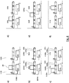
- the Fig. 4 a) represents an example of the initial situation for running through the method according to the invention.
- Two conveyor segments 1100-1200 are shown.
- a transport item 40 is located on the conveyor segment 1100.
- the Hall sensor 1104a of the first control unit is already activated by a user by stopping a magnet, which is symbolized by the closed switching contact.
- Fig. 4 b the magnet was removed from the Hall sensor 1104b again, which is symbolized by the open switching contact.
- the learning mode is activated and the conveyor drive 1101 is activated with a first direction of rotation 1106a.
- the conveyor drive 1201 is also activated by means of a command which is transmitted to the control unit of the conveyor segment 1200 by means of the bus communication and has the direction of rotation 1206a.
- the conveying direction 1105a and 1205a is formed in the two conveying segments, whereby the transported goods are conveyed.
- Fig. 4 c the method step is shown which is triggered when the sensor unit 1103a is activated.
- the directions of rotation of the conveyor drives are reversed by the control units and the directions of rotation 1106b and 1206b for the conveyor drives result.
- the new directions of rotation 1106b and 1206b of the conveyor drives are stored in the control units as the new preferred direction of rotation.
- the goods to be transported are conveyed in the downstream direction according to the installation.
- the goods to be transported will then continue to be transported downstream, such as Fig. 4 d) clarified.
- Fig. 4 f represents the continued transport of the transported goods.
- Fig. 5 shows a conveyor device in which a control unit 2102 controls a plurality of conveyor segments 2100, 2200, 2300, 2400, the control being carried out by the program units 2107-2110 that are executed within the control unit 2102.
- the program units 2107-2110 control the conveyor drives 2101, 2201, 2301, 2401 and control the direction of rotation 2106, 2206, 2306, 2406 of the conveyor drives in order to convey a transport item 40 downstream.
- the program units can control the conveying directions 2105, 2205, 2305, 2405 in the conveying segments 2100, 2200, 2300, 2400.
- the program units 2107-2110 evaluate the signals from the sensor units 2103, 2203, 2303, 2403.
- the program units can exchange data within the control unit in order to e.g. B. to detect the direction of rotation of the conveyor drives.
- the control unit 2102 is integrated into the bus communication 70 and enables data exchange, e.g. B. with other control units.
- Fig. 6 describes an exemplary sequence for recognizing the direction of rotation of the conveyor drives.
- the method begins with a start step 610 and checks in a test step 612 whether the first and the second sensor unit were activated within a first period of time by the conveyance of the object. If the first and the second sensor unit were activated within a first period of time, then step 614 is carried out.
- step 614 the direction of rotation of the first conveyor drive is stored in the first control unit and the direction of rotation of the second conveyor drive is stored in the second control unit.
- the method for detecting the direction of rotation of the conveyor drives then ends in step 628.
- test step 615 is carried out, checking whether the first sensor unit was activated within a first period of time. If the first sensor unit was not activated within a first period of time, then test step 616 is carried out, wherein in test step 616 it is checked whether the second sensor unit was activated within the first period of time. If the second sensor unit was activated within the first time period, then step 614 is carried out in which the direction of rotation of the first conveyor drive is stored in the first control unit and the direction of rotation of the second conveyor drive is stored in the second control unit. The method then ends in step 628.
- step 618 is carried out in which the direction of rotation of the first conveyor drive is reversed by the first control unit.
- step 620 it is checked whether the second sensor unit was activated within a first period of time. If the second sensor unit was activated within a first period of time, step 614 is carried out in which the direction of rotation of the first conveyor drive is stored in the first control unit and the direction of rotation of the second conveyor drive is stored in the second control unit. The method then ends in step 628. If, in step 620, the second sensor unit is not activated within a first time period, then step 622 is carried out. In step 622, the direction of rotation of the second conveyor drive is reversed by the second control unit.
- step 624 it is checked whether the second sensor unit was activated by the object within a first period of time. If the second sensor unit was activated by the object, step 614 is carried out in which the direction of rotation of the first conveyor drive is stored in the first control unit and the direction of rotation of the second conveyor drive is stored in the second control unit. The method then ends in step 628. If, in test step 624, the second sensor unit is not activated within a first time period, step 626 is carried out. In step 626, an error message is generated because the method could not determine a combination of directions of rotation that convey the object in such a way that the first and the second control unit are activated by the object within a first period of time.
- Step 626 is followed by step 628, with which the method is ended. If the first sensor unit was activated within a first period of time in test step 615, then step 630 is carried out below, in which the direction of rotation of the second conveyor drive is reversed. In the following test step 632 it is checked whether the second sensor unit was activated within a first period of time. If the second sensor unit has been activated, step 614 is carried out in which the direction of rotation of the first conveyor drive is stored in the first control unit and the direction of rotation of the second conveyor drive is stored in the second control unit. The method then ends in step 628.
- step 634 is carried out and the direction of rotation of the first conveyor drive is reversed by the first control unit.
- step 636 it is checked whether the second sensor unit was activated within a first period of time. Became the second sensor unit activated within a first period of time, step 614 is carried out, in which the direction of rotation of the first conveyor drive is stored in the first control unit and the direction of rotation of the second conveyor drive is stored in the second control unit. The method then ends in step 628. If in test step 636 the second sensor unit is not activated within a first time period, step 638 is carried out.
- step 638 the direction of rotation of the second conveyor drive is reversed by the second control unit.
- step 640 it is checked whether the second sensor unit was activated within a first period of time. If the second sensor unit was activated within a first period of time, step 614 is carried out in which the direction of rotation of the first conveyor drive is stored in the first control unit and the direction of rotation of the second conveyor drive is stored in the second control unit. The method then ends in step 628. If in test step 640 the second sensor unit is not activated within a first time period, step 626 is carried out.
- step 626 an error message is generated because the method could not determine a combination of directions of rotation that convey the object in such a way that the first and the second control unit are activated by the object within a first period of time.
- step 628 is followed by step 628, with which the method is ended.
- Fig. 7 describes an example of a schematic representation of the visualization of the neighborhood relationships.
- the conveyor lines 700, 710 and 720 consist of a different number of conveyor segments.
- the control units of all conveyor segments are integrated into bus communication 770.
- a central processing unit 780 is integrated into the bus communication.
- This central processing unit can read out the addresses from the control units by means of bus communication and determine the neighborhood relationships.
- the central processing unit is signal-connected to an optical output unit 790 by means of an electrical connection 772.
- the neighborhood relationships are visualized by means of this output unit 790.
- an individual bus address read out from the control unit of the conveyor segment 701 can be displayed on the optical output unit in the form of a suitable display form 711. This can be done analogously for all further conveyor segments.
- a representation of the affiliation of the conveyor segments to a conveyor line, e.g. B. 700 can take place by means of the subaddress of a control unit and the subaddress 712 can be displayed on the optical output unit in a suitable
Landscapes
- Engineering & Computer Science (AREA)
- Physics & Mathematics (AREA)
- General Physics & Mathematics (AREA)
- Automation & Control Theory (AREA)
- General Engineering & Computer Science (AREA)
- Manufacturing & Machinery (AREA)
- Quality & Reliability (AREA)
- Computer Networks & Wireless Communication (AREA)
- Signal Processing (AREA)
- Control Of Conveyors (AREA)
Claims (17)
- Procédé d'installation d'une unité de commande dans un dispositif de convoyage, dans lequel une première unité de commande commande un premier segment de convoyage se trouvant en amont et une seconde unité de commande commande un deuxième segment de convoyage se trouvant en aval,
dans lequel le premier segment de convoyage comportea. un premier entraînement de convoyage pour le convoyage d'un objet par le premier segment de convoyage, etb. une première unité de capteur pour la détection d'un objet au niveau d'une position à l'intérieur du premier segment de convoyage,et le deuxième segment de convoyage comportea. un deuxième entraînement de convoyage pour le convoyage d'un objet par le deuxième segment de convoyage, etb. une deuxième unité de capteur pour la détection d'un objet au niveau d'une position à l'intérieur du deuxième segment de convoyage, etle premier entraînement de convoyage et la première unité de capteur sont couplés en signal à la première unité de commande afin de commander le premier entraînement de convoyage et afin de recevoir un premier signal de capteur de la première unité de capteur et
le deuxième entraînement de convoyage et la deuxième unité de capteur sont couplés en signal à la seconde unité de commande afin de commander le deuxième entraînement de convoyage et afin de recevoir un second signal de capteur de la deuxième unité de capteur,
dans lequel la première et la seconde unité de commande sont couplées en signal entre elles au moyen d'une communication bus, avec les étapes :i) de placement d'un objet sur le premier segment de convoyage,ii) d'activation d'un mode d'apprentissage au niveau de la première et de la seconde unité de commande,iii) d'activation du premier et deuxième entraînement de convoyage par la première et la seconde unité de commande correspondantes,iv) de convoyage automatique de l'objet en direction du deuxième segment de convoyage,v) d'enregistrement d'un paramètre d'installation dans la seconde unité de commande en fonction du déclenchement du premier et/ou second signal de capteur,dans lequel à l'étape v) les étapes suivantes sont réalisées :- la génération d'un message de remise avec une information d'adresse bus dans la première unité de commande,- la transmission du message de remise au moyen de la communication bus de la première à la seconde unité de commande, caractérisé en ce qu'à l'étape v) l'étape suivante est réalisée :- l'attribution d'une adresse bus individuelle dérivée de l'information d'adresse bus à la seconde unité de commande au moyen de l'enregistrement de l'adresse bus individuelle comme paramètre d'installation dans la seconde unité de commande lorsqu'un second signal de capteur est déclenché par l'objet, dans lequel l'adresse bus est associée à la seconde unité de commande et permet un adressage de la seconde unité de commande. - Procédé selon la revendication 1, caractérisé en ce qu'à l'étape iv) une reconnaissance d'un sens de rotation préféré du premier et/ou du deuxième entraînement de convoyage qui convoie l'objet en aval, est réalisée, avec les étapes :a. de convoyage de l'objet,b. de déclenchement du premier et/ou du second signal de capteur par l'objet,c. de détection du déclenchement du premier et/ou second signal de capteur par la première unité de commande,d. d'inversion éventuelle du sens de rotation du premier et/ou deuxième entraînement de convoyage en fonction du premier et/ou second signal de capteur,e. d'enregistrement d'un premier ou second sens de rotation du premier entraînement de convoyage dans la première unité de commande comme sens de rotation en aval.
- Procédé selon la revendication 2,
caractérisé en ce que l'inversion du sens de rotation du premier et/ou deuxième entraînement de convoyage est effectuée par l'absence du premier et/ou du second signal de capteur. - Procédé selon la revendication 3,
caractérisé en ce que l'inversion du sens de rotation du premier et/ou deuxième entraînement de convoyage est effectuée en fonction de l'absence du premier et/ou du second signal de capteur dans un intervalle prédéterminé après l'activation du premier entraînement de convoyage. - Procédé selon la revendication 2,
caractérisé en ce que l'inversion du sens de rotation du premier et/ou deuxième entraînement de convoyage est effectuée par déclenchement du premier et/ou du second signal de capteur. - Procédé selon la revendication 2,
caractérisé en ce que l'inversion du sens de rotation du premier entraînement de convoyage est déclenchée au moyen du premier signal de capteur, et l'inversion du sens de rotation du deuxième entraînement de convoyage est déclenchée au moyen du second signal de capteur. - Procédé selon l'une des revendications 2 à 6,
caractérisé en ce que, lors du déclenchement du premier signal de capteur et du déclenchement consécutif du second signal de capteur dans une première période après déclenchement du premier signal de capteur, le sens de rotation du premier entraînement de convoyage dans la première unité de commande est enregistré comme sens de rotation en aval et le sens de rotation du deuxième entraînement de convoyage dans la seconde unité de commande est enregistrée comme sens de rotation en aval. - Procédé selon l'une des revendications 2 à 7,
caractérisé en ce qu'après un nombre prédéterminé d'inversions du sens de rotation le mode d'apprentissage est terminé, en particulier qu'après quatre inversions du sens de rotation le mode d'apprentissage est terminé. - Procédé selon l'une des revendications 2 à 8,
caractérisé en ce que par l'activation du premier et du deuxième entraînement de convoyage, de préférence par activation de tous les entraînements de convoyage, en particulier par activation de tous les entraînements de convoyage à l'exception des entraînements de convoyage qui sont raccordés à une unité de commande, dans laquelle une adresse bus a déjà été enregistrée, l'objet est convoyé. - Procédé selon la revendication 1,
caractérisé en ce qu'une unité de traitement centrale peut échanger au moyen de la communication bus des données avec la première et la seconde unité de commande, et l'unité de traitement centrale réalise les étapes suivantes :i) de lecture d'adresses bus individuelles à partir des unités de commande au moyen de la communication bus,ii) de détermination de rapports de voisinage des unités de commande au moyen de la suite des adresses bus individuelles,iii) d'enregistrement des rapports de voisinage dans l'unité de traitement centrale,iv) de visualisation des rapports de voisinage par une interface utilisateur graphique. - Procédé selon l'une des revendications précédentes,
caractérisé en ce que la seconde unité de commande comporte- une première unité de programme qui est couplée en signal au deuxième entraînement de convoyage et à la deuxième unité de capteur du deuxième segment de convoyage, et- une seconde unité de programme qui est couplée en signal à un troisième entraînement de convoyage et à une troisième unité de capteur d'un troisième segment de convoyage,- et que la première et la seconde unité de programme sont couplées en signal à l'intérieur de la seconde unité de commande, en particulier que la première et la seconde unité de programme sont couplées en signal à l'intérieur de l'unité de commande à un accumulateur électrique commun, etque la première et la seconde unité de commande réalisent à l'intérieur d'une unité de commande la reconnaissance du sens de rotation du deuxième et troisième entraînement de convoyage qui convoie l'objet en aval, selon l'une des revendication 3 à 10, dans lequel la première ou la seconde unité de programme entre à la place de la première ou seconde unité de commande, et la communication des unités de programme est effectuée au moyen du couplage en signal à l'intérieur de l'unité de commande. - Procédé selon l'une des revendications précédentes,
caractérisé en ce que la première unité de commande est amenée dans le mode d'apprentissage, par- le déclenchement d'un commutateur, en particulier par déclenchement d'un contact Reed ou d'un capteur à effet Hall avec un signal magnétique ou,- la réception d'une commande dans la première unité de commande au moyen de la communication bus. - Procédé selon la revendication 1,
caractérisé en ce qu'une adresse bus individuelle de la première unité de commande- a été fixée auparavant manuellement par l'utilisateur sous la forme d'une suite de chiffres ou- a été définie par un numéro d'origine préconfiguré. - Procédé selon l'une des revendications précédentes,
caractérisé en ce qu'un nom de texte en clair individuel est attribué à une unité de commande, en particulier qu'un nom de texte en clair est attribué à la première unité de commande, qui a été fixé auparavant manuellement par l'utilisateur sous la forme d'une suite de lettres et/ou suite de chiffres ou a été défini par un nom de texte en clair d'origine préconfiguré. - Procédé selon l'une des revendications précédentes,
caractérisé en ce qu'une pluralité d'unités de commande est adressée par une sous-adresse simultanément au moyen de la communication bus, en particulier que simultanément une pluralité d'unités de commande est amenée dans le mode d'apprentissage, qui possèdent une sous-adresse identique, dans lequel la sous-adresse- a été fixée auparavant manuellement par l'utilisateur sous la forme d'une suite de chiffres ou- a été définie par un numéro d'origine préconfiguré. - Procédé selon l'une des revendications précédentes,
caractérisé en ce que dans une étape de paramétrage des paramètres de convoyage sont attribués au premier segment de convoyage en ce que des paramètres de convoyage correspondants sont enregistrés dans la première unité de commande, et de préférence après déclenchement du second signal de capteur par l'objet les paramètres de convoyage de la première unité de commande sont enregistrés dans la seconde unité de commande. - Procédé selon l'une des revendications précédentes,
caractérisé en ce qu'une unité de commande signale visuellement et/ou acoustiquement- la fin du mode d'apprentissage et/ou- la reconnaissance défectueuse du sens de rotation en ce que l'unité de commande du segment de convoyage- émet des signaux optiques qui sont générés par des composants émettant de la lumière de l'unité de commande du segment de convoyage et/ou- commande un modèle prédéterminé d'une séquence d'activation et de désactivation de l'entraînement de convoyage du segment de convoyage et/ou- active un convertisseur électroacoustique qui est intégré dans l'unité de commande.
Applications Claiming Priority (2)
| Application Number | Priority Date | Filing Date | Title |
|---|---|---|---|
| DE102015106034.5A DE102015106034A1 (de) | 2015-04-20 | 2015-04-20 | Installationsverfahren zum Einrichten von Fördervorrichtungen |
| PCT/EP2016/058719 WO2016169962A1 (fr) | 2015-04-20 | 2016-04-20 | Procédé d'installation pour régler des dispositifs de convoyage |
Publications (2)
| Publication Number | Publication Date |
|---|---|
| EP3286115A1 EP3286115A1 (fr) | 2018-02-28 |
| EP3286115B1 true EP3286115B1 (fr) | 2021-01-27 |
Family
ID=55806330
Family Applications (1)
| Application Number | Title | Priority Date | Filing Date |
|---|---|---|---|
| EP16717907.6A Active EP3286115B1 (fr) | 2015-04-20 | 2016-04-20 | Procédé d'installation pour régler des dispositifs de convoyage |
Country Status (7)
| Country | Link |
|---|---|
| US (1) | US10556754B2 (fr) |
| EP (1) | EP3286115B1 (fr) |
| JP (1) | JP6563033B2 (fr) |
| CN (1) | CN107750229B (fr) |
| DE (1) | DE102015106034A1 (fr) |
| ES (1) | ES2865158T3 (fr) |
| WO (1) | WO2016169962A1 (fr) |
Families Citing this family (21)
| Publication number | Priority date | Publication date | Assignee | Title |
|---|---|---|---|---|
| DE102014222171A1 (de) | 2014-10-30 | 2016-05-04 | Interroll Holding Ag | Fördereinrichtung für Förderanlagen, modulares System und Verfahren zum Herstellen einer solchen Fördereinrichtung |
| DE102015106024B4 (de) | 2015-04-20 | 2023-06-07 | Interroll Holding Ag | Fördervorrichtung mit Konfigurationsänderung |
| DE102015106026B3 (de) | 2015-04-20 | 2016-08-25 | Interroll Holding Ag | Verfahren zum Austausch einer Steuerungseinheit in einer Fördervorrichtung |
| DE102015106034A1 (de) | 2015-04-20 | 2016-10-20 | Interroll Holding Ag | Installationsverfahren zum Einrichten von Fördervorrichtungen |
| DE102015107167A1 (de) | 2015-05-07 | 2016-11-10 | Interroll Holding Ag | Steuerungseinheit für eine Fördervorrichtung mit Hardware-Erkennung |
| DE102016112036A1 (de) | 2016-06-30 | 2018-01-04 | Interroll Holding Ag | Antriebseinheit für einen Trommelmotor, Trommelmotor, Hinterflansch und Herstellungsverfahren |
| DE102016112051B4 (de) | 2016-06-30 | 2024-01-04 | Interroll Holding Ag | Modulsystem für motorbetriebene Förderrollen |
| DE102016112054B4 (de) | 2016-06-30 | 2021-08-12 | Interroll Holding Ag | Trommelmotor mit alternativer Getriebeaufnahme |
| DE102016114524B4 (de) | 2016-08-05 | 2020-09-03 | Interroll Holding Ag | Trommelmotor mit Frequenzumrichter und optionalem Bandspannungssensor |
| DE102016114672A1 (de) | 2016-08-08 | 2018-02-08 | Interroll Holding Ag | Elektrische Steckverbindung für Motorrollen |
| US10569967B2 (en) * | 2016-12-13 | 2020-02-25 | Mark Rolfes | Integrated control systems and methods |
| EP3373232B1 (fr) | 2017-03-09 | 2020-12-09 | Interroll Holding AG | Agencement intralogistique |
| CN111196474A (zh) * | 2018-11-16 | 2020-05-26 | 北汽福田汽车股份有限公司 | 旋转移行输送系统和滑撬输送方法 |
| DE102018133481A1 (de) * | 2018-12-21 | 2020-06-25 | Interroll Holding Ag | Förderanordnung mit integrierter Sensorfunktionseinheit |
| EP3825263A1 (fr) * | 2019-11-20 | 2021-05-26 | Siemens Aktiengesellschaft | Procédé de configuration par ordinateur d'une application d'entraînement régulée d'un système logistique |
| DE102019131773B4 (de) * | 2019-11-25 | 2022-01-13 | Krohne Messtechnik Gmbh | Verfahren zum Initialisieren eines Bussystems für eine Prozessanlage und Bussystem |
| DE102019135620B4 (de) * | 2019-12-20 | 2021-10-28 | Interroll Holding Ag | Optisches Anlernen von kameraerfassten Wegstrecken |
| DE102019135624B4 (de) * | 2019-12-20 | 2024-10-24 | Interroll Holding Ag | Fördervorrichtung mit modular aufgebauten Steuerungseinheiten |
| KR102326017B1 (ko) * | 2019-12-30 | 2021-11-15 | 세메스 주식회사 | 이송 장치 및 이송 방법 |
| US11799758B2 (en) | 2020-10-23 | 2023-10-24 | Insight Automation, Inc. | System and method for relative addressing based on physical topology |
| CN114988053B (zh) * | 2022-05-25 | 2024-04-19 | 杭州华立科技有限公司 | 物料运输系统、方法及装置 |
Citations (1)
| Publication number | Priority date | Publication date | Assignee | Title |
|---|---|---|---|---|
| WO2002003153A2 (fr) * | 2000-06-29 | 2002-01-10 | Honeywell Internation Inc. | Configuration automatisee de communications permettant de collecter des dispositifs de facon ordonnee |
Family Cites Families (78)
| Publication number | Priority date | Publication date | Assignee | Title |
|---|---|---|---|---|
| AT13066B (fr) | 1902-03-17 | 1903-08-25 | Berthold Kaufmann | |
| DE3538173C1 (en) | 1985-10-26 | 1987-01-02 | Warsteiner Antriebstechnik | Friction-drum motor for conveyor belts |
| CN2033808U (zh) | 1988-05-28 | 1989-03-08 | 上海电视一厂 | 链传动谐波减速电动滚筒 |
| US5485590A (en) | 1990-01-08 | 1996-01-16 | Allen-Bradley Company, Inc. | Programmable controller communication interface module which is configurable by a removable memory cartridge |
| DE4230729A1 (de) | 1991-09-24 | 1993-03-25 | Selve Ernst Gmbh Co Kg | Vorrichtung zur antriebsabschaltung des motors elektrisch betriebener rollaeden, rolltore, markisen o. dgl. |
| US5180344A (en) | 1992-03-23 | 1993-01-19 | Interroll Holding A.G. | Motorized pulley with internal mounts |
| US5530643A (en) * | 1993-08-24 | 1996-06-25 | Allen-Bradley Company, Inc. | Method of programming industrial controllers with highly distributed processing |
| US5442248A (en) | 1994-04-11 | 1995-08-15 | Interroll Holding, A.G. | Motorized pulley with integral electrical connector |
| CN2199164Y (zh) | 1994-09-15 | 1995-05-31 | 天津市减速机总厂 | 油浸式电动滚筒 |
| DK9600125U4 (da) | 1996-04-11 | 1997-07-25 | Interroll A S | Tromlemotor |
| US20040194101A1 (en) | 1997-08-21 | 2004-09-30 | Glanzer David A. | Flexible function blocks |
| JP3378462B2 (ja) * | 1997-03-31 | 2003-02-17 | 伊東電機株式会社 | コンベアシステム及びその制御方法 |
| DE69803477T2 (de) | 1997-10-07 | 2002-09-19 | Interroll Holding Ag, San Antonio | Trommelmotor |
| WO1999028794A2 (fr) | 1997-11-26 | 1999-06-10 | Moeller Gmbh | Mini-automate |
| SE512647C2 (sv) * | 1998-01-22 | 2000-04-17 | Sunds Defibrator Ind Ab | Förfarande och styrsystem för att styra ett transportörsystem samt en anläggning för balning av pappersmassa |
| US6117318A (en) | 1998-11-06 | 2000-09-12 | Emerson Electric Co. | Rotating motorized conveyor pulley drum having a magnetic particulate trap |
| US6240335B1 (en) | 1998-12-14 | 2001-05-29 | Palo Alto Technologies, Inc. | Distributed control system architecture and method for a material transport system |
| US6701214B1 (en) | 2000-04-27 | 2004-03-02 | Rockwell Automation Technologies, Inc. | Driver board control system for modular conveyer with address-based network for inter-conveyor communication |
| AU2001222539A1 (en) | 2000-04-27 | 2001-11-12 | Rockwell Technologies, Llc | Driver board control system for modular conveyor with address-based network for inter-conveyor communication |
| JP3600860B2 (ja) | 2000-11-22 | 2004-12-15 | 伊東電機株式会社 | モータ内蔵ローラ及びモータ内蔵ローラ用のユニット |
| WO2002098768A1 (fr) | 2001-06-05 | 2002-12-12 | Siemens Aktiengesellschaft | Rouleau de mesure et de detection |
| JP2005231745A (ja) | 2001-06-27 | 2005-09-02 | Ito Denki Kk | ゾーンコントローラ |
| JP2003026603A (ja) | 2001-07-17 | 2003-01-29 | Sumika Life Tech Co Ltd | コンパニオンアニマルの外部寄生虫駆除用水性滴下剤 |
| JP2003104534A (ja) | 2001-09-27 | 2003-04-09 | Watanabe Kikai Seisakusho:Kk | ユニットコンベア及び搬送装置 |
| JP3933017B2 (ja) | 2002-09-11 | 2007-06-20 | Nok株式会社 | 金属・ゴム複合材料の製造法 |
| US6860381B2 (en) | 2003-01-29 | 2005-03-01 | Hytrol Conveyor Company, Inc. | Decentralized drive system for a conveyor |
| DE10336304B4 (de) | 2003-07-31 | 2020-08-27 | Interroll Holding Ag | Motorbetriebene Förderrolle, Steuervorrichtung für eine motorbetriebene Förderrolle, Rollenförderanlage und Steuerverfahren für eine Rollenförderanlage |
| DK200400405A (da) | 2004-03-12 | 2005-09-13 | Interroll Joki As | En tromlemotor med et kabelstik |
| DE102004025924A1 (de) * | 2004-05-27 | 2005-12-22 | Siemens Ag | Solarwechselrichter und Photovoltaikanlage mit mehreren Solarwechselrichtern |
| DE102005013285B4 (de) | 2005-03-22 | 2009-09-03 | Continental Automotive Gmbh | Verfahren zum Konfigurieren eines Steuergeräts und Steuergerät |
| US20060293782A1 (en) | 2005-06-27 | 2006-12-28 | Rees Steven D | Method for regulating the flow of product along an accumulation conveyor |
| DE102006054575B4 (de) | 2006-11-20 | 2008-09-04 | Interroll-Holding Ag | Förderrolle mit Reinigungsfunktion |
| DE202007016420U1 (de) | 2007-11-22 | 2008-02-07 | Holzma Plattenaufteiltechnik Gmbh | Fördervorrichtung für plattenförmige Werkstücke |
| DE102008053557B4 (de) | 2008-03-11 | 2017-07-06 | Sew-Eurodrive Gmbh & Co Kg | Vorrichtung zur Steuerung einer Anlage und Verfahren zur Einrichtung und Bedienung der Steuerung einer Anlage |
| WO2009139068A1 (fr) | 2008-05-16 | 2009-11-19 | 株式会社協和製作所 | Rouleau de transporteur à rouleaux à moteur intégré et dispositif transporteur à rouleaux utilisant ce dernier |
| EP2161223B2 (fr) | 2008-09-07 | 2023-02-22 | Itoh Denki Co., Ltd. | Rouleau motorisé et unité de moteur pour rouleau motorisé |
| US20110137587A1 (en) | 2009-06-09 | 2011-06-09 | Tca Technologies Inc. | Systems and methods for monitoring rollers for conveyors |
| US8284993B2 (en) | 2009-06-18 | 2012-10-09 | Hytrol Conveyor Company, Inc. | Decentralized tracking of packages on a conveyor |
| AT508863A3 (de) * | 2009-09-17 | 2011-12-15 | Tgw Mechanics Gmbh | Fördereinrichtung und verfahren zur ermittlung der reihenfolge von antrieben |
| DE202009012822U1 (de) | 2009-09-24 | 2011-02-10 | Interroll Holding Ag | Trommelmotor |
| DE202009012821U1 (de) | 2009-09-24 | 2011-02-17 | Interroll Holding Ag | Förderrollenantriebseinheit |
| US20120024669A1 (en) * | 2010-07-29 | 2012-02-02 | Danelski Darin L | Networked Motorized Drive Roller Conveyor |
| DE102010050524B4 (de) | 2010-11-08 | 2024-07-04 | Krones Aktiengesellschaft | Maschine zur Verarbeitung und/oder Verpackung von Gegenständen und Verfahren zum Modifizieren einer Transportstrecke dieser Maschine |
| DE102010044027A1 (de) | 2010-11-17 | 2012-05-24 | Klug Gmbh Integrierte Systeme | Staufördersystem mit zwei Kommunikationssystemen |
| US8695786B2 (en) * | 2010-12-07 | 2014-04-15 | Interroll Holding Ag | Singulated release for zoned conveyor systems |
| US8550234B2 (en) * | 2010-12-07 | 2013-10-08 | Interroll Corporation | Sequential controlled start-up for zoned conveyor systems |
| DE102011011625A1 (de) * | 2011-02-17 | 2012-08-23 | Krones Aktiengesellschaft | Vorrichtung und Verfahren zum Transportieren von Behältnissen oder Behältnisgebinden mit drahtloser Zustandserfassung |
| DE102011004802A1 (de) | 2011-02-25 | 2012-08-30 | Interroll-Holding Ag | Verfahren zur Einrichtung einer Fördervorrichtung |
| US9581994B2 (en) * | 2011-04-05 | 2017-02-28 | Fisher-Rosemount Systems, Inc. | Methods and apparatus to manage process control resources |
| US8757363B2 (en) * | 2011-05-09 | 2014-06-24 | Insight Automation, Inc. | Conveyor controllers |
| AT511630B1 (de) | 2011-06-29 | 2013-04-15 | Tgw Mechanics Gmbh | Förderrolle |
| DE102011109531B4 (de) | 2011-08-05 | 2021-10-14 | Sew-Eurodrive Gmbh & Co Kg | Anlage zur Energieversorgung einer Maschine mittels eines Mobilteils und Verfahren zum Betreiben einer Anlage |
| US9004263B2 (en) | 2011-11-30 | 2015-04-14 | Milwaukee Electronics Corporation | Conveyor drive with integrated controller |
| JP5099464B1 (ja) | 2011-12-29 | 2012-12-19 | 富田製薬株式会社 | 重炭酸イオン濃度可変型の透析液の調製装置及び調製方法、重炭酸イオン濃度可変型の透析剤、並びに重炭酸イオン濃度可変型の透析システム |
| US9846415B2 (en) | 2012-01-19 | 2017-12-19 | Globalfoundries Singapore Pte. Ltd. | Efficient transfer of materials using automated guided vehicles in semiconductor manufacturing |
| DE202012000793U1 (de) | 2012-01-30 | 2012-04-27 | Eco-Scheibenantriebe Gmbh | Getriebeloser, elektrischer Antriebsmotor mit zuschaltbarer Leistung |
| US9359142B2 (en) | 2012-03-20 | 2016-06-07 | P. Ellegaard A/S | Hygienic drum motor |
| FR2991974B1 (fr) | 2012-06-15 | 2016-05-06 | Savoye | Systeme de convoyage modulaire, dispositif de controle et procede correspondants |
| WO2014011459A1 (fr) | 2012-07-11 | 2014-01-16 | Mercury Capital Management L.L.C. | Véhicule de levage à guidage automatique pour manipulation de plateaux d'entrepôts |
| WO2014057984A1 (fr) | 2012-10-10 | 2014-04-17 | 伊東電機株式会社 | Élément de transmission de puissance et rouleau à moteur intégré |
| EP2925646B1 (fr) * | 2012-11-30 | 2019-05-08 | Intelligrated Headquarters LLC | Commande d'accumulateur |
| JP6045366B2 (ja) | 2013-01-23 | 2016-12-14 | 光洋電子工業株式会社 | 信号入力装置 |
| US8983651B2 (en) * | 2013-03-14 | 2015-03-17 | Insight Automation, Inc. | Zone controller for modular conveyor system |
| DE102013207760B4 (de) * | 2013-04-29 | 2024-02-22 | Phoenix Contact Gmbh & Co. Kg | Elektrisches Interfacemodul |
| WO2014178399A1 (fr) | 2013-04-30 | 2014-11-06 | 伊東電機株式会社 | Dispositif transporteur à rouleaux, dispositif de commande et procédé de détection d'anomalie de dispositif mécanique |
| ITBG20130031A1 (it) | 2013-10-11 | 2015-04-12 | Rulli Rulmeca S P A | Rullo di trasporto motorizzato |
| AT514999B1 (de) * | 2013-11-06 | 2015-11-15 | Tgw Mechanics Gmbh | Verfahren zum Adressieren/Reihen linear verketteter Steuerkomponenten einer Förderanlage |
| CN203682423U (zh) | 2013-12-30 | 2014-07-02 | 上海宝羽自动化系统设备有限公司 | 一种电动滚筒的动力输出装置 |
| DE102014222171A1 (de) | 2014-10-30 | 2016-05-04 | Interroll Holding Ag | Fördereinrichtung für Förderanlagen, modulares System und Verfahren zum Herstellen einer solchen Fördereinrichtung |
| US10623244B2 (en) | 2014-12-19 | 2020-04-14 | Emerson Process Management Lllp | Data transfer on an industrial process network |
| DE102015104130A1 (de) | 2015-03-19 | 2016-09-22 | Interroll Holding Ag | Förderrolle mit Drehmomentübertragungsabschnitt und Herstellungsverfahren |
| DE102015106024B4 (de) | 2015-04-20 | 2023-06-07 | Interroll Holding Ag | Fördervorrichtung mit Konfigurationsänderung |
| DE102015106034A1 (de) | 2015-04-20 | 2016-10-20 | Interroll Holding Ag | Installationsverfahren zum Einrichten von Fördervorrichtungen |
| DE102015106026B3 (de) | 2015-04-20 | 2016-08-25 | Interroll Holding Ag | Verfahren zum Austausch einer Steuerungseinheit in einer Fördervorrichtung |
| JP6610922B2 (ja) | 2015-04-24 | 2019-11-27 | 伊東電機株式会社 | モータ内蔵ローラ、及び動力伝達部材 |
| DE102015107167A1 (de) | 2015-05-07 | 2016-11-10 | Interroll Holding Ag | Steuerungseinheit für eine Fördervorrichtung mit Hardware-Erkennung |
| DE102015114030A1 (de) | 2015-08-24 | 2017-03-02 | Interroll Holding Ag | Trommelmotor und Sensorkartusche für einen Trommelmotor |
| EP3481651B1 (fr) | 2016-07-06 | 2021-02-24 | Bridgestone Americas Tire Operations, LLC | Appareil de roulage à plat post-vulcanisation et/ou de réduction du bruit et procédé de fabrication dudit appareil |
-
2015
- 2015-04-20 DE DE102015106034.5A patent/DE102015106034A1/de not_active Ceased
-
2016
- 2016-04-20 ES ES16717907T patent/ES2865158T3/es active Active
- 2016-04-20 EP EP16717907.6A patent/EP3286115B1/fr active Active
- 2016-04-20 US US15/567,737 patent/US10556754B2/en active Active
- 2016-04-20 JP JP2017554798A patent/JP6563033B2/ja active Active
- 2016-04-20 CN CN201680023266.5A patent/CN107750229B/zh active Active
- 2016-04-20 WO PCT/EP2016/058719 patent/WO2016169962A1/fr not_active Ceased
Patent Citations (1)
| Publication number | Priority date | Publication date | Assignee | Title |
|---|---|---|---|---|
| WO2002003153A2 (fr) * | 2000-06-29 | 2002-01-10 | Honeywell Internation Inc. | Configuration automatisee de communications permettant de collecter des dispositifs de facon ordonnee |
Also Published As
| Publication number | Publication date |
|---|---|
| US20180127217A1 (en) | 2018-05-10 |
| CN107750229A (zh) | 2018-03-02 |
| ES2865158T3 (es) | 2021-10-15 |
| WO2016169962A1 (fr) | 2016-10-27 |
| EP3286115A1 (fr) | 2018-02-28 |
| JP6563033B2 (ja) | 2019-08-21 |
| DE102015106034A1 (de) | 2016-10-20 |
| JP2018513079A (ja) | 2018-05-24 |
| CN107750229B (zh) | 2021-05-07 |
| US10556754B2 (en) | 2020-02-11 |
Similar Documents
| Publication | Publication Date | Title |
|---|---|---|
| EP3286115B1 (fr) | Procédé d'installation pour régler des dispositifs de convoyage | |
| EP3292056B1 (fr) | Dispositif de transport avec une unité de commande à détection de matériel | |
| DE102015106024B4 (de) | Fördervorrichtung mit Konfigurationsänderung | |
| EP3286615A2 (fr) | Procédé de remplacement d'une unité de commande dans un dispositif de transport | |
| DE102011004802A1 (de) | Verfahren zur Einrichtung einer Fördervorrichtung | |
| DE2817089B2 (de) | Gefahrenmeldeanlage | |
| EP2012201A1 (fr) | Procédé destiné à la programmation d'une commande de sécurité | |
| EP4236631B1 (fr) | Agencement de commande segmenté | |
| DE102012001615A1 (de) | Modulanordnung | |
| DE202010018479U1 (de) | Fördereinrichtung mit verbesserter Positionserkennung geförderter Objekte | |
| DE212006000033U1 (de) | Elektrisch dezentral steuerbare Fördervorrichtung für stückhaftes Fördergut sowie entsprechendes Fördersystem | |
| EP1890210A1 (fr) | Procédé et dispositif destinés au marquage de l'état de fonctionnement d'un élément de commande | |
| WO2001015385A2 (fr) | Procede de configuration d'un noeud sur et systeme de commande sur comportant un tel noeud | |
| DE102019135620A1 (de) | Optisches Anlernen von kameraerfassten Wegstrecken | |
| EP3744665B1 (fr) | Procédé de surveillance et/ou de maintenance d'une installation de transport et installation de transport | |
| DE102019204709A1 (de) | Vorrichtung und Verfahren zur Verbesserung der Kommunikation von modularen Fördersystemen | |
| EP2762667B1 (fr) | Système d'entraînement et méthode de fonctionnement d'un système d'entraînement | |
| EP3557598A1 (fr) | Commutateur de sécurité | |
| DE102005006554A1 (de) | Verfahren zum Betreiben einer Anlage und fahrerloses Transportsystem | |
| DE102020115104A1 (de) | Sicherheitssteuerungssystem und Verfahren zum Ausführen einer Sicherheitsfunktion | |
| EP2217977B1 (fr) | Système d'automatisation et dispositif de commande pour identifier un élément de connexion | |
| EP2318813B1 (fr) | Procédé pour faire fonctionner un système d'appareils de terrain | |
| EP2036800A2 (fr) | Commande d'élément de signal électronique et sûre destinée à l'exécution d'une marche de véhicules sur rail | |
| EP3509316A1 (fr) | Réseau de sécurité et capteur de sécurité | |
| EP3825798B1 (fr) | Commande mobile d'installations |
Legal Events
| Date | Code | Title | Description |
|---|---|---|---|
| STAA | Information on the status of an ep patent application or granted ep patent |
Free format text: STATUS: THE INTERNATIONAL PUBLICATION HAS BEEN MADE |
|
| PUAI | Public reference made under article 153(3) epc to a published international application that has entered the european phase |
Free format text: ORIGINAL CODE: 0009012 |
|
| STAA | Information on the status of an ep patent application or granted ep patent |
Free format text: STATUS: REQUEST FOR EXAMINATION WAS MADE |
|
| 17P | Request for examination filed |
Effective date: 20171120 |
|
| AK | Designated contracting states |
Kind code of ref document: A1 Designated state(s): AL AT BE BG CH CY CZ DE DK EE ES FI FR GB GR HR HU IE IS IT LI LT LU LV MC MK MT NL NO PL PT RO RS SE SI SK SM TR |
|
| AX | Request for extension of the european patent |
Extension state: BA ME |
|
| DAV | Request for validation of the european patent (deleted) | ||
| DAX | Request for extension of the european patent (deleted) | ||
| STAA | Information on the status of an ep patent application or granted ep patent |
Free format text: STATUS: EXAMINATION IS IN PROGRESS |
|
| 17Q | First examination report despatched |
Effective date: 20190228 |
|
| GRAP | Despatch of communication of intention to grant a patent |
Free format text: ORIGINAL CODE: EPIDOSNIGR1 |
|
| STAA | Information on the status of an ep patent application or granted ep patent |
Free format text: STATUS: GRANT OF PATENT IS INTENDED |
|
| INTG | Intention to grant announced |
Effective date: 20200414 |
|
| GRAS | Grant fee paid |
Free format text: ORIGINAL CODE: EPIDOSNIGR3 |
|
| GRAJ | Information related to disapproval of communication of intention to grant by the applicant or resumption of examination proceedings by the epo deleted |
Free format text: ORIGINAL CODE: EPIDOSDIGR1 |
|
| GRAL | Information related to payment of fee for publishing/printing deleted |
Free format text: ORIGINAL CODE: EPIDOSDIGR3 |
|
| STAA | Information on the status of an ep patent application or granted ep patent |
Free format text: STATUS: EXAMINATION IS IN PROGRESS |
|
| INTC | Intention to grant announced (deleted) | ||
| GRAP | Despatch of communication of intention to grant a patent |
Free format text: ORIGINAL CODE: EPIDOSNIGR1 |
|
| STAA | Information on the status of an ep patent application or granted ep patent |
Free format text: STATUS: GRANT OF PATENT IS INTENDED |
|
| INTG | Intention to grant announced |
Effective date: 20201002 |
|
| GRAA | (expected) grant |
Free format text: ORIGINAL CODE: 0009210 |
|
| STAA | Information on the status of an ep patent application or granted ep patent |
Free format text: STATUS: THE PATENT HAS BEEN GRANTED |
|
| AK | Designated contracting states |
Kind code of ref document: B1 Designated state(s): AL AT BE BG CH CY CZ DE DK EE ES FI FR GB GR HR HU IE IS IT LI LT LU LV MC MK MT NL NO PL PT RO RS SE SI SK SM TR |
|
| RAP1 | Party data changed (applicant data changed or rights of an application transferred) |
Owner name: INTERROLL HOLDING AG |
|
| REG | Reference to a national code |
Ref country code: GB Ref legal event code: FG4D Free format text: NOT ENGLISH |
|
| REG | Reference to a national code |
Ref country code: CH Ref legal event code: EP |
|
| REG | Reference to a national code |
Ref country code: AT Ref legal event code: REF Ref document number: 1358176 Country of ref document: AT Kind code of ref document: T Effective date: 20210215 |
|
| REG | Reference to a national code |
Ref country code: IE Ref legal event code: FG4D Free format text: LANGUAGE OF EP DOCUMENT: GERMAN |
|
| REG | Reference to a national code |
Ref country code: DE Ref legal event code: R096 Ref document number: 502016012302 Country of ref document: DE |
|
| REG | Reference to a national code |
Ref country code: NL Ref legal event code: FP |
|
| REG | Reference to a national code |
Ref country code: LT Ref legal event code: MG9D |
|
| PG25 | Lapsed in a contracting state [announced via postgrant information from national office to epo] |
Ref country code: LT Free format text: LAPSE BECAUSE OF FAILURE TO SUBMIT A TRANSLATION OF THE DESCRIPTION OR TO PAY THE FEE WITHIN THE PRESCRIBED TIME-LIMIT Effective date: 20210127 Ref country code: PT Free format text: LAPSE BECAUSE OF FAILURE TO SUBMIT A TRANSLATION OF THE DESCRIPTION OR TO PAY THE FEE WITHIN THE PRESCRIBED TIME-LIMIT Effective date: 20210527 Ref country code: NO Free format text: LAPSE BECAUSE OF FAILURE TO SUBMIT A TRANSLATION OF THE DESCRIPTION OR TO PAY THE FEE WITHIN THE PRESCRIBED TIME-LIMIT Effective date: 20210427 Ref country code: GR Free format text: LAPSE BECAUSE OF FAILURE TO SUBMIT A TRANSLATION OF THE DESCRIPTION OR TO PAY THE FEE WITHIN THE PRESCRIBED TIME-LIMIT Effective date: 20210428 Ref country code: FI Free format text: LAPSE BECAUSE OF FAILURE TO SUBMIT A TRANSLATION OF THE DESCRIPTION OR TO PAY THE FEE WITHIN THE PRESCRIBED TIME-LIMIT Effective date: 20210127 Ref country code: HR Free format text: LAPSE BECAUSE OF FAILURE TO SUBMIT A TRANSLATION OF THE DESCRIPTION OR TO PAY THE FEE WITHIN THE PRESCRIBED TIME-LIMIT Effective date: 20210127 |
|
| PG25 | Lapsed in a contracting state [announced via postgrant information from national office to epo] |
Ref country code: LV Free format text: LAPSE BECAUSE OF FAILURE TO SUBMIT A TRANSLATION OF THE DESCRIPTION OR TO PAY THE FEE WITHIN THE PRESCRIBED TIME-LIMIT Effective date: 20210127 Ref country code: PL Free format text: LAPSE BECAUSE OF FAILURE TO SUBMIT A TRANSLATION OF THE DESCRIPTION OR TO PAY THE FEE WITHIN THE PRESCRIBED TIME-LIMIT Effective date: 20210127 Ref country code: RS Free format text: LAPSE BECAUSE OF FAILURE TO SUBMIT A TRANSLATION OF THE DESCRIPTION OR TO PAY THE FEE WITHIN THE PRESCRIBED TIME-LIMIT Effective date: 20210127 Ref country code: SE Free format text: LAPSE BECAUSE OF FAILURE TO SUBMIT A TRANSLATION OF THE DESCRIPTION OR TO PAY THE FEE WITHIN THE PRESCRIBED TIME-LIMIT Effective date: 20210127 |
|
| PG25 | Lapsed in a contracting state [announced via postgrant information from national office to epo] |
Ref country code: IS Free format text: LAPSE BECAUSE OF FAILURE TO SUBMIT A TRANSLATION OF THE DESCRIPTION OR TO PAY THE FEE WITHIN THE PRESCRIBED TIME-LIMIT Effective date: 20210527 |
|
| REG | Reference to a national code |
Ref country code: ES Ref legal event code: FG2A Ref document number: 2865158 Country of ref document: ES Kind code of ref document: T3 Effective date: 20211015 |
|
| REG | Reference to a national code |
Ref country code: DE Ref legal event code: R097 Ref document number: 502016012302 Country of ref document: DE |
|
| PG25 | Lapsed in a contracting state [announced via postgrant information from national office to epo] |
Ref country code: SM Free format text: LAPSE BECAUSE OF FAILURE TO SUBMIT A TRANSLATION OF THE DESCRIPTION OR TO PAY THE FEE WITHIN THE PRESCRIBED TIME-LIMIT Effective date: 20210127 Ref country code: CZ Free format text: LAPSE BECAUSE OF FAILURE TO SUBMIT A TRANSLATION OF THE DESCRIPTION OR TO PAY THE FEE WITHIN THE PRESCRIBED TIME-LIMIT Effective date: 20210127 Ref country code: EE Free format text: LAPSE BECAUSE OF FAILURE TO SUBMIT A TRANSLATION OF THE DESCRIPTION OR TO PAY THE FEE WITHIN THE PRESCRIBED TIME-LIMIT Effective date: 20210127 |
|
| PG25 | Lapsed in a contracting state [announced via postgrant information from national office to epo] |
Ref country code: DK Free format text: LAPSE BECAUSE OF FAILURE TO SUBMIT A TRANSLATION OF THE DESCRIPTION OR TO PAY THE FEE WITHIN THE PRESCRIBED TIME-LIMIT Effective date: 20210127 Ref country code: MC Free format text: LAPSE BECAUSE OF FAILURE TO SUBMIT A TRANSLATION OF THE DESCRIPTION OR TO PAY THE FEE WITHIN THE PRESCRIBED TIME-LIMIT Effective date: 20210127 Ref country code: RO Free format text: LAPSE BECAUSE OF FAILURE TO SUBMIT A TRANSLATION OF THE DESCRIPTION OR TO PAY THE FEE WITHIN THE PRESCRIBED TIME-LIMIT Effective date: 20210127 Ref country code: SK Free format text: LAPSE BECAUSE OF FAILURE TO SUBMIT A TRANSLATION OF THE DESCRIPTION OR TO PAY THE FEE WITHIN THE PRESCRIBED TIME-LIMIT Effective date: 20210127 |
|
| PLBE | No opposition filed within time limit |
Free format text: ORIGINAL CODE: 0009261 |
|
| STAA | Information on the status of an ep patent application or granted ep patent |
Free format text: STATUS: NO OPPOSITION FILED WITHIN TIME LIMIT |
|
| PG25 | Lapsed in a contracting state [announced via postgrant information from national office to epo] |
Ref country code: LU Free format text: LAPSE BECAUSE OF NON-PAYMENT OF DUE FEES Effective date: 20210420 |
|
| 26N | No opposition filed |
Effective date: 20211028 |
|
| REG | Reference to a national code |
Ref country code: BE Ref legal event code: MM Effective date: 20210430 |
|
| PG25 | Lapsed in a contracting state [announced via postgrant information from national office to epo] |
Ref country code: AL Free format text: LAPSE BECAUSE OF FAILURE TO SUBMIT A TRANSLATION OF THE DESCRIPTION OR TO PAY THE FEE WITHIN THE PRESCRIBED TIME-LIMIT Effective date: 20210127 |
|
| PG25 | Lapsed in a contracting state [announced via postgrant information from national office to epo] |
Ref country code: SI Free format text: LAPSE BECAUSE OF FAILURE TO SUBMIT A TRANSLATION OF THE DESCRIPTION OR TO PAY THE FEE WITHIN THE PRESCRIBED TIME-LIMIT Effective date: 20210127 |
|
| PG25 | Lapsed in a contracting state [announced via postgrant information from national office to epo] |
Ref country code: IE Free format text: LAPSE BECAUSE OF NON-PAYMENT OF DUE FEES Effective date: 20210420 |
|
| PG25 | Lapsed in a contracting state [announced via postgrant information from national office to epo] |
Ref country code: IS Free format text: LAPSE BECAUSE OF FAILURE TO SUBMIT A TRANSLATION OF THE DESCRIPTION OR TO PAY THE FEE WITHIN THE PRESCRIBED TIME-LIMIT Effective date: 20210527 |
|
| PG25 | Lapsed in a contracting state [announced via postgrant information from national office to epo] |
Ref country code: BE Free format text: LAPSE BECAUSE OF NON-PAYMENT OF DUE FEES Effective date: 20210430 |
|
| PG25 | Lapsed in a contracting state [announced via postgrant information from national office to epo] |
Ref country code: HU Free format text: LAPSE BECAUSE OF FAILURE TO SUBMIT A TRANSLATION OF THE DESCRIPTION OR TO PAY THE FEE WITHIN THE PRESCRIBED TIME-LIMIT; INVALID AB INITIO Effective date: 20160420 |
|
| PG25 | Lapsed in a contracting state [announced via postgrant information from national office to epo] |
Ref country code: CY Free format text: LAPSE BECAUSE OF FAILURE TO SUBMIT A TRANSLATION OF THE DESCRIPTION OR TO PAY THE FEE WITHIN THE PRESCRIBED TIME-LIMIT Effective date: 20210127 |
|
| PG25 | Lapsed in a contracting state [announced via postgrant information from national office to epo] |
Ref country code: MK Free format text: LAPSE BECAUSE OF FAILURE TO SUBMIT A TRANSLATION OF THE DESCRIPTION OR TO PAY THE FEE WITHIN THE PRESCRIBED TIME-LIMIT Effective date: 20210127 |
|
| PGFP | Annual fee paid to national office [announced via postgrant information from national office to epo] |
Ref country code: CH Payment date: 20240501 Year of fee payment: 9 |
|
| PGFP | Annual fee paid to national office [announced via postgrant information from national office to epo] |
Ref country code: AT Payment date: 20240417 Year of fee payment: 9 |
|
| PG25 | Lapsed in a contracting state [announced via postgrant information from national office to epo] |
Ref country code: MT Free format text: LAPSE BECAUSE OF FAILURE TO SUBMIT A TRANSLATION OF THE DESCRIPTION OR TO PAY THE FEE WITHIN THE PRESCRIBED TIME-LIMIT Effective date: 20210127 |
|
| PGFP | Annual fee paid to national office [announced via postgrant information from national office to epo] |
Ref country code: NL Payment date: 20250422 Year of fee payment: 10 |
|
| PGFP | Annual fee paid to national office [announced via postgrant information from national office to epo] |
Ref country code: DE Payment date: 20250417 Year of fee payment: 10 |
|
| PGFP | Annual fee paid to national office [announced via postgrant information from national office to epo] |
Ref country code: GB Payment date: 20250423 Year of fee payment: 10 Ref country code: ES Payment date: 20250519 Year of fee payment: 10 |
|
| PGFP | Annual fee paid to national office [announced via postgrant information from national office to epo] |
Ref country code: IT Payment date: 20250430 Year of fee payment: 10 |
|
| PGFP | Annual fee paid to national office [announced via postgrant information from national office to epo] |
Ref country code: FR Payment date: 20250422 Year of fee payment: 10 |
|
| PGFP | Annual fee paid to national office [announced via postgrant information from national office to epo] |
Ref country code: BG Payment date: 20250415 Year of fee payment: 10 |
|
| REG | Reference to a national code |
Ref country code: CH Ref legal event code: H13 Free format text: ST27 STATUS EVENT CODE: U-0-0-H10-H13 (AS PROVIDED BY THE NATIONAL OFFICE) Effective date: 20251125 |
|
| PG25 | Lapsed in a contracting state [announced via postgrant information from national office to epo] |
Ref country code: TR Free format text: LAPSE BECAUSE OF FAILURE TO SUBMIT A TRANSLATION OF THE DESCRIPTION OR TO PAY THE FEE WITHIN THE PRESCRIBED TIME-LIMIT Effective date: 20210127 |
|
| REG | Reference to a national code |
Ref country code: AT Ref legal event code: MM01 Ref document number: 1358176 Country of ref document: AT Kind code of ref document: T Effective date: 20250420 |
|
| PG25 | Lapsed in a contracting state [announced via postgrant information from national office to epo] |
Ref country code: AT Free format text: LAPSE BECAUSE OF NON-PAYMENT OF DUE FEES Effective date: 20250420 |
|
| PG25 | Lapsed in a contracting state [announced via postgrant information from national office to epo] |
Ref country code: CH Free format text: LAPSE BECAUSE OF NON-PAYMENT OF DUE FEES Effective date: 20250430 |