EP3290384B1 - Einrichtung zum heben, senken oder halten einer last - Google Patents
Einrichtung zum heben, senken oder halten einer last Download PDFInfo
- Publication number
- EP3290384B1 EP3290384B1 EP17167050.8A EP17167050A EP3290384B1 EP 3290384 B1 EP3290384 B1 EP 3290384B1 EP 17167050 A EP17167050 A EP 17167050A EP 3290384 B1 EP3290384 B1 EP 3290384B1
- Authority
- EP
- European Patent Office
- Prior art keywords
- load
- active
- hydraulic cylinder
- winch
- piston
- Prior art date
- Legal status (The legal status is an assumption and is not a legal conclusion. Google has not performed a legal analysis and makes no representation as to the accuracy of the status listed.)
- Active
Links
Images


Classifications
-
- B—PERFORMING OPERATIONS; TRANSPORTING
- B66—HOISTING; LIFTING; HAULING
- B66D—CAPSTANS; WINCHES; TACKLES, e.g. PULLEY BLOCKS; HOISTS
- B66D1/00—Rope, cable, or chain winding mechanisms; Capstans
- B66D1/28—Other constructional details
- B66D1/40—Control devices
- B66D1/48—Control devices automatic
- B66D1/52—Control devices automatic for varying rope or cable tension, e.g. when recovering craft from water
-
- B—PERFORMING OPERATIONS; TRANSPORTING
- B66—HOISTING; LIFTING; HAULING
- B66C—CRANES; LOAD-ENGAGING ELEMENTS OR DEVICES FOR CRANES, CAPSTANS, WINCHES, OR TACKLES
- B66C13/00—Other constructional features or details
- B66C13/02—Devices for facilitating retrieval of floating objects, e.g. for recovering crafts from water
Definitions
- the invention relates to a device for lifting, lowering or holding a load according to the preamble of patent claim 1.
- Sea state or swell compensation devices hereinafter also referred to as HCS - are used, for example, in offshore/marine technology when a load is to be placed from a ship using a crane onto an object supported on the seabed, for example a platform.
- HCS Sea state or swell compensation devices
- Such a task occurs when assembling drilling rigs or offshore wind turbines or when a drill string is lowered from a floating platform and this is raised and lowered by the sea.
- heavy measuring devices or supply stations for robots or the like are lowered from a ship to great depths using a winch, whereby the tether is then exposed to considerable tensile loads caused by the sea.
- a linearly adjustable unit for example a hydraulic cylinder or a rotationally operated unit, for example a hydraulic motor
- a hydropneumatic storage unit the pressure of which is designed so that the load is supported in a central position without sea conditions - the hydropneumatic storage unit acts thus as a kind of gas spring.
- Such passive units are structurally tailored to the respective application and the associated loads, so that adaptation to different loads is only possible with great effort.
- Such passive systems are often arranged between the actual crane hook and the load and are therefore below sea level when lowering.
- active systems are preferably used in which a linear drive (hydraulic cylinder) or a rotary drive (hydromotor) is designed with a position control system through which the load is controlled by controlling the Drive can always be kept in the predetermined position.
- Such active systems are usually arranged on the ship so that they also have to move the weight of the crane rope, the crane blocks (pulley) and the crane hook, so that the payload is reduced by the additional weight of these components.
- the load is compensated via a passive hydropneumatic storage system and, on the other hand, the target position of the load is kept constant via an active control system.
- a passive hydropneumatic storage system has the advantage that only the balancing movement of the load has to be effected via the active system the actual support takes place via the passive system.
- Such combination systems are particularly necessary when a load is to be lifted from or lowered onto the seabed or from a platform anchored thereon at a predetermined speed.
- a similar system is also in the one mentioned at the beginning US 4,121,806 explained.
- passively acting hydraulic cylinders preloaded via a hydropneumatic storage unit and active hydraulic cylinders with position control are arranged parallel to one another in a compensation unit, to which the actual crane hook is then attached, which is then connected to the load via the crane rope.
- the US 4,021,019 shows a system in which an active hydraulic cylinder is integrated into a passive hydraulic cylinder.
- the FR 2 383 876 discloses a combination of an active and a passive compensation device for an object floating on a water surface.
- a load is to be lowered from a ship onto a platform supported on the seabed or another ship using the lifting device, care must be taken to ensure that the load is not lowered too quickly and thus damaged when placed on the platform/ship becomes. This can happen, for example, if the active compensation unit fails due to an accident.
- US 3912227 discloses the preamble of claim 1.
- the invention is based on the object of creating a device for lifting, lowering or holding a load in which operational safety is increased. This task is achieved by a device with the combination of features of claim 1.
- the device for raising, lowering or holding a load has a compensation device which is designed to compensate for relative movements of the load with respect to a target position, particularly caused by sea conditions.
- the load can be moved towards or away from the target position by means of a lifting device.
- a passive compensation device is assigned to the lifting device.
- an active compensation unit is provided, which can be controlled via a control unit depending on a relative movement of the load or an effective force.
- the passive compensation device is designed to support at least 100 percent of the weight of the load.
- the active compensation unit is designed so that it acts on the load in the opposite direction to the support direction.
- the active compensation unit acts in the opposite direction to the supporting direction, i.e. in the lowering direction.
- a component within the passive compensation device may be adjusted up to a stop.
- the passive compensation device overcompensates the load. This is achieved by selecting their preload so that the supporting force resulting from this compensation is greater than the acting load or force. Therefore, if the active compensation unit fails due to overcompensation, the load is raised according to the stroke of the passive compensation device.
- the structure of the device according to the invention is particularly simple if the passive compensation device has a hydraulic cylinder with a piston which limits a pressure space effective in the support direction.
- This pressure chamber is in operative connection with a hydropneumatic storage unit, the pressure of which is preferably selected depending on the load and which can be designed in the usual way as a hydropneumatic piston storage unit with one or more downstream gas bottles.
- the active compensation unit has an active winch, the winch cable of which acts on the load directly or indirectly via the hydraulic cylinder or bypassing the hydraulic cylinder.
- the winch cable is deflected via a deflection roller.
- Such a deflection roller can be mounted on the cylinder side or on a roller block carrying the hydraulic cylinder.
- the winch cable of the active winch engages a pushrod, which is slidably guided on the hydraulic cylinder or on the roller block.
- the winch cable does not engage directly on the hydraulic cylinder or the load but is guided via the deflection block to another active winch.
- a coupling rod can engage the winch rope in a section of the winch rope between the deflection roller and one of the active winches.
- Such a coupling rod can in turn engage the load or a piston of the hydraulic cylinder.
- the coupling rod can engage a push rod connected to the load, which is guided on the hydraulic cylinder or on the roller block.
- the deflection roller drives a pinion which meshes with a drive element, for example a rack, which acts directly or indirectly on the load.
- the winch cable engages an active piston of a push cylinder, this active piston delimiting an active pressure chamber which is in pressure medium connection with a pressure chamber of the hydraulic cylinder which acts against the support direction.
- the force resulting from the overcompensation or prestress corresponds to approximately 105% to 150%, preferably approximately 110%, of the load or force to be moved.
- the device is designed with compensation devices to compensate for relative movements of the load caused by sea waves with respect to a target position.
- Figures 2 to 6 Variants of the exemplary embodiment according to Figure 1 .
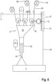
- FIG. 1 shows a simplified schematic diagram of a ship or floating crane 2 designed with a device according to the invention for heave compensation (HCS) 1, via which a load L is to be placed on another ship or on the seabed 4 or a platform anchored thereon.
- the device 1 motion compensation device, HCS
- a loading crane is mounted on the indicated floating crane 2, which has, in a manner known per se, a stationary roller or a plurality of stationary rollers 14 (discs) and a movable roller or a plurality of movable rollers (disks) 16, which together with a support cable 18 form a pulley 20.
- the movable rollers 16 (loose part) are mounted on a roller block 22.
- the support cable 18, which is fixed at one end to the deck, can be retrieved or lowered/lowered by means of a winch 21 of the loading crane 10 in order to raise or lower the load L.
- the power of the winch 21 is then translated accordingly via the pulley 20.
- a passive hydraulic cylinder 24 is attached to the roller block 22, which is designed as a synchronous cylinder.
- a piston 26 divides the hydraulic cylinder 24 into a pressure chamber 28 effective in the support direction and a pressure chamber 30 effective in the lowering direction.
- the pressure chamber 28 is connected to a hydropneumatic storage unit 32, which can be designed as usual as a hydropneumatic piston accumulator with one or more downstream gas bottles and through which the pressure chamber 28 is subjected to a preload pressure.
- the force resulting from this preload corresponds to approximately 110% of the load L to be moved. This load L is thus overcompensated, so that the load L is raised solely by the effect of the compensation device 6.
- the pressure chamber 28 and the hydropneumatic storage unit 32 form a type of gas spring.
- the hydraulic cylinder 24 is designed as a synchronous cylinder.
- a piston rod 34 on the load side in FIG. 1 carries the load L, which is attached to the piston rod 34, for example via a crane hook or the like.
- the other, in figure 1 upper piston rod 36 carries at its end section a console 38, on which a traction device, for example a winch cable 40 or a chain of the active compensation unit 8, engages. Since the piston rod 36 has the same diameter as the piston rod 34, no compensation is necessary due to the ambient pressure increasing with water depth.
- the winch cable 40 engages the console 38 in the lowering direction and is deflected by means of a deflection roller 42 in the direction of an active winch 44 of the active compensation unit 8 located on the deck of the floating crane 2.
- a deflection roller 42 In the area in which the winch cable 40 is in active engagement with the deflection roller 42, it can be designed as a chain, toothed belt or other tensile and wear-resistant traction device.
- the deflection roller 42 is in Figure 1 illustrated embodiment mounted on the hydraulic cylinder 24 or on the roller block 22.
- the active winch 44 in order to hold the piston 26 and the load in a fixed position relative to the roller block 22 or to lower the load L relative to the roller block 22 and thus to extend the piston rod 34, the active winch 44 must be controlled in such a way that the overcompensation via the Passive compensation device is compensated (when holding) or overdriven (when lowering). In the exemplary embodiment shown, the active compensation unit thus pushes the load L in the lowering direction.
- the hydraulic cylinder 24 of the passive compensation device 6 is designed as a differential cylinder and only has the piston rod 34.
- the pressure chamber 30 can, for example, be assigned a device for compensating for the water depth.
- the pressure chamber 30 can also be connected to a pressure medium compensation tank.
- the active compensation unit 8 has, as in the exemplary embodiment Figure 1 again a deflection roller 42, over which a winch cable 40 (or other traction device) is guided, which engages a console 38.
- the console 38 is not attached to the piston 26 but to a push rod 46. This push rod 46 engages parallel to the piston rod 28 on the crane hook on which the load hangs.
- the push rod 46 is axially displaceable in the vertical direction on a guide 48, which in turn is fixed to the hydraulic cylinder 24 or to the roller block 22.
- the push rod 46 is shown as shown Figure 2 actively applied downwards with a force.
- This force must be greater than the overcompensation via the passive compensation device 6 in order to be able to hold or lower the load L relative to the roller block 22.
- the active compensation unit 8 acts hydraulically/pneumatically on the hydraulic cylinder 24 of the passive compensation device 6.
- a push cylinder 50 is provided parallel to the hydraulic cylinder 24, which is connected to the hydraulic cylinder 24, for example via a bridge 52.
- the push cylinder 50 is designed as a differential cylinder and has an active piston 54 and an active piston rod 56, which is always subjected to tension and on which a winch cable 40 of the active winch 44 engages.
- the active piston 54 delimits an active pressure chamber 58 on the piston rod side, which is also connected to the pressure chamber 30 of the pressure chamber 30 via a connecting line 60 or a channel formed in the bridge 52 as a differential cylinder executed hydraulic cylinder 24 is connected.
- the active piston rod 56 When retrieving the winch cable 40, the active piston rod 56 is extended and corresponding pressure medium is pushed from the active pressure chamber 58 via the connecting line 60 into the pressure chamber 30, so that the load L against its preload/overcompensation in the pressure chamber 28 to compensate for swell or the like relative to the roller block 22 is lowered.
- an expansion tank (not shown) can be assigned to it.
- Figure 4 shows an exemplary embodiment with a compared to the exemplary embodiment Figure 1 somewhat more complex active compensation unit 8, via which the movements of the load L relative to the roller block 22 in the raising and lowering directions can be actively controlled.
- the passive compensation device 6 shown has a similar structure to that in the exemplary embodiment Figure 1 an active winch 44, the winch rope 40 of which is initially deflected via the deflection roller 42, which in this exemplary embodiment is mounted on the roller block 22, on which the loose rollers 16 are also arranged.
- the winch cable 40 does not end at a component located in the area of the roller block 22, as in the previously described exemplary embodiments, but extends away from the deflection roller 42 to a further active winch 64, which, like the active winch 44, can also be controlled via the control unit, not shown to pull in or lower the winch rope 40.
- An angled coupling rod 68 engages on the strand 66 extending between the further active winch 64 and the deflection roller 42. This is connected to the winch cable 40, for example via a clamp.
- This coupling rod 68 then engages with a horizontal leg 70 on the piston rod 36 of the piston 26.
- the hydraulic cylinder 24 is the same as in the exemplary embodiment Figure 1 designed as a synchronous cylinder.
- the load L can be lowered relative to the roller block 22 be that the winch rope 40 is unwound from one active winch 64 and wound onto the other active winch 44 or by the active winches 44, 64 being operated in the same direction with a speed difference.
- the latter is the case, for example, when the load L is lowered via the lifting device and the push rod 68 is nevertheless acted upon against the supporting force of the passive compensation device 6, with both active winches 44, 64 being controlled accordingly via the control unit, not shown.
- the push rod 68 can be acted upon in the lifting direction by reversing the active winches 44, 64, so that - as with conventional systems - it also acts in the supporting direction.
- the exemplary embodiment according to Figure 5 is a variant of the exemplary embodiment according to Figure 4 .
- the hydraulic cylinder 24 is as in the exemplary embodiment Figure 2 designed as a differential cylinder 24, with the load L acting on the piston rod 34.
- a push rod 46 is mounted so that it can move in the axial direction via a guide 48, which engages the crane hook on which the load L hangs, bypassing the hydraulic cylinder 24.
- the push rod 46 is actuated in accordance with the exemplary embodiment Figure 4 .
- two active winches 44, 64 are provided, between which a traction means, for example the winch cable 40, which is deflected over the deflection roller 42, extends.
- the coupling rod 68 which is connected to the strand 66 in a tension-proof manner, engages directly on the push rod 46, so that the overcompensation by appropriately controlling the active winches 44, 64 allows the push rod 46 to be extended against the preload acting on the load L in order to increase the load L relative to the roller block 22 to lower.
- FIG. 6 shows another exemplary embodiment based on the Figures 4 and 5 explained concept. Also with the in Figure 6
- the hydraulic cylinder 24 is designed as a differential cylinder.
- the active compensation unit 8 in turn has two active winches 44, 64 for retrieving or rewinding (unwinding, winding up) the winch rope 40 or other traction means.
- the winch cable 40 is deflected via a deflection roller 42 mounted on the roller block 22.
- This deflection roller 42 drives a pinion 72 via a chain, a toothed belt, a shaft or the like, which in turn meshes with a toothed rack 74, which also has a pressure-resistant rod 76 connected to the load L.
- the direction of rotation of the pinion 72 can be selected and the load L can either be lowered relative to the roller block 22 against the overcompensation or raised to support the passive compensation device 6 via the operative connection with the rack 74 and the rod 76 become.
- gear transmission with a pinion 72 and a rack 74
- another transmission can also be used.
- the actuators are designed as winches (winch 21, active winches 44, 64).
- other actuators such as linear drives or the like, can also be used instead of such winches.
- the winch cable 40 can be designed as a chain or other wear-resistant traction device in the area of the deflection.
- the section to be wound onto the winches can also be made of high-strength plastic, for example Dyneema ® .
- the maximum cable length wound on the active winches 44 and 64 corresponds approximately only to the maximum lift of the load, so that the active actuators can be designed to be relatively small.
- the active one Compensation unit can be retrofitted with little effort because the active and passive systems can essentially be operated independently of one another.
- the application of the device is not limited to compensating for movements caused by sea conditions but is generally applicable where relative movements of a load caused by external circumstances are to be compensated for.
- the active compensation unit can also be designed as a mobile solution.
- the pressure in the pressure chamber 28 is so great that the force generated by this pressure on the piston 26 overcompensates for the weight of the load L.
- the force is 10 percent greater than the weight.
- the piston rod 34 would therefore retract if the active compensation unit 8 on the crane hook did not exert a force in the direction of lowering the load, which is equal to the proportion of the force generated by the pressure in the pressure chamber 28 that goes beyond the weight force.
- the piston 26 is located approximately in the middle of the hydraulic cylinder 24, so that it can make the same stroke in the opposite direction.
- the winch 44 or the winches 44 and 64 are controlled so that the deflection roller 42 follows the movement.
- the force generated by the active compensation unit is increased, so that the sum of the weight of the load and the force generated by the active compensation device 8 outweighs the force generated by the pressure prevailing in the pressure chamber 28 and the piston rod 34 extends.
- the movement of the load is not affected by the movement of the ship's crane. If the ship's crane lowers due to a wave, the force generated by the active compensation unit is reduced, so that the sum of the weight of the load and the force generated by the active compensation device 8 becomes smaller than the force generated by the pressure prevailing in the pressure chamber 28 and the piston rod 34 retracts. Again, the movement of the load is not affected by the movement of the ship's crane.
Landscapes
- Engineering & Computer Science (AREA)
- Mechanical Engineering (AREA)
- Jib Cranes (AREA)
Description
- Die Erfindung betrifft eine Einrichtung zum Heben, Senken oder Halten einer Last gemäß dem Oberbegriff des Patentanspruches 1.
- Seegangs- oder Dünungskompensationseinrichtungen (Heave Compensation System) - im Folgenden auch HCS genannt - werden beispielsweise in der Offshore-/Marinetechnik eingesetzt, wenn eine Last von einem Schiff mittels eines Krans auf ein am Meeresboden abgestütztes Objekt, beispielsweise eine Plattform abgesetzt werden soll. Eine derartige Aufgabenstellung liegt bei der Montage von Bohrinseln oder Offshore-Windkraftanlagen vor oder wenn ein Bohrstrang von einer schwimmenden Plattform aus abgesenkt wird und diese durch den Seegang angehoben und abgesenkt wird. In der Forschung werden schwere Messgeräte oder Versorgungsstationen für Roboter oder dergleichen von einem Schiff über eine Winde in große Tiefen abgesenkt, wobei dann durch den Seegang verursacht das Halteseil erheblichen Zugbelastungen ausgesetzt ist.
- Zum Ausgleich derartiger durch Seegang oder Dünung verursachten Relativbewegungen der Last zur jeweils vorgegebenen Zielposition sind passive und aktive Systeme bekannt. Bei einem passiven System, wie es beispielsweise in der Beschreibungseinleitung der
US 4,121,806 beschrieben ist, wird eine linear verstellbare Einheit, beispielsweise ein Hydrozylinder oder eine rotatorisch betriebene Einheit, beispielsweise ein Hydromotor in Abstützrichtung über eine hydropneumatischen Speichereinheit beaufschlagt, dessen Druck so ausgelegt ist, dass die Last ohne Seegang in einer Mittelposition abgestützt ist - die hydropneumatische Speichereinheit wirkt somit als eine Art Gasfeder. - Derartige passive Einheiten sind konstruktiv auf den jeweiligen Anwendungszweck und die zugehörigen Lasten abgestimmt, so dass eine Anpassung an unterschiedliche Lasten nur mit größerem Aufwand möglich ist. Derartige Passivsysteme sind häufig zwischen dem eigentlichen Kranhaken und der Last angeordnet und befinden sich somit beim Absenken unterhalb des Meeresspiegels.
- Ein Problem bei derartigen passiven Systemen besteht darin, dass die Aufladung der hydropneumatischen Speichereinheit in Abhängigkeit von der Last und dem Seegang und auch von der Eintauchtiefe angepasst werden muss. In der
US 7,934,561 B1 ist ein passives System mit einer Wassertiefenkompensation gezeigt, über die sich die Einflüsse der Wassertiefe beim Absenken der Last etwas kompensieren lassen. - Bei Anwendungen, bei denen es auf eine sehr präzise Führung der Last beim Absenken ankommt, werden vorzugsweise aktive Systeme verwendet, bei denen ein Linearantrieb (Hydrozylinder) oder ein rotatorischer Antrieb (Hydromotor) mit einem Positionsregelsystem ausgeführt ist, durch das die Last durch Ansteuerung des Antriebs stets auf der vorbestimmten Position gehalten werden kann.
- Derartige aktive Systeme werden üblicher Weise auf dem Schiff angeordnet, so dass sie auch das Gewicht des Kranseils, der Kranblöcke (Flaschenzug) und des Kranhakens bewegen müssen, so dass die Nutzlast durch das zusätzliche Gewicht dieser Komponenten reduziert ist.
- Bei größeren Lasten wird üblicher Weise ein Kombination eines aktiven und passiven Systems eingesetzt, wie es beispielsweise in der
EP 1 869 282 B1 erläutert ist. - Dabei wird zum einen die Last über ein passives hydropneumatisches Speichersystem kompensiert und zum anderen die Sollposition der Last über ein aktives Regelsystem konstant gehalten. Ein derartiges System hat den Vorteil, dass über das aktive System lediglich die Ausgleichsbewegung der Last bewirkt werden muss, während das eigentliche Abstützen über das passive System erfolgt. Derartige Kombinationssysteme sind insbesondere dann erforderlich, wenn eine Last mit einer vorbestimmten Geschwindigkeit vom Meeresboden oder von einer auf diesem verankerten Plattform abgehoben oder auf diese abgesenkt werden soll. Ein ähnliches System ist auch in der eingangs genannten
US 4,121,806 erläutert. Bei dieser Anordnung sind passiv wirkende, über eine hydropneumatische Speichereinheit vorgespannte Hydrozylinder und aktive Hydrozylinder mit einer Positionsregelung parallel zueinander in einer Kompensationseinheit angeordnet, an der dann der eigentliche Kranhaken befestigt ist, die dann über das Kranseil mit der Last verbunden ist. - Die
US 4,021,019 zeigt ein System, bei dem ein aktiver Hydrozylinder in einen passiven Hydrozylinder integriert ist. - Derartige Systeme haben einen relativ komplexen Aufbau und werden seitens der Hersteller bei der Konzeption des Krans integriert. Eine Nachrüstung des aktiven Systems bei bestehenden Kränen, die lediglich mit einem passiven Kompensationssystem ausgeführt sind, ist nur mit äußerst großem Aufwand möglich, da ein Eingriff in die Kranstruktur des bestehenden Designs erforderlich ist und auch zusätzliche hydraulische Leistung bereitgestellt werden muss. Hinzu kommt, dass existierende Krandesigns aufgrund Restriktionen im Hinblick auf die maximale Seilgeschwindigkeit, das Gewicht und den Durchmesser der Seilscheiben/Blöcke und die Steifigkeit der Konstruktion unterliegen, so dass eine Nachrüstung mit einem aktiven System nahezu ausgeschlossen ist.
- In den Druckschriften
DE 10 2015 225 936 A1 undEP 2 896 589 A1 sind jeweils Systeme gezeigt, bei denen eine aktive Kompensationseinheit und eine mit einer passiven Kompensationseinrichtung versehene Hubeinrichtung getrennt an der Last angreifen. Aufgrund der getrennten Kraftflusslinien des aktiven und passiven Teils können bestehende Systeme mit einer aktiven Kompensationseinheit nachgerüstet werden. - Die
FR 2 383 876 US 3912227 offenbart den Oberbegriff des Anspruchs 1. - Demgegenüber liegt der Erfindung die Aufgabe zugrunde, eine Einrichtung zum Heben, Senken oder Halten einer Last zu schaffen, bei der die Betriebssicherheit erhöht ist. Diese Aufgabe wird durch eine Einrichtung mit der Merkmalskombination des Patentanspruches 1 gelöst.
- Vorteilhafte Weiterbildungen der Erfindung sind Gegenstand der Unteransprüche. Erfindungsgemäß hat die Einrichtung zum Heben, Senken oder Halten einer Last eine Kompensationseinrichtung, die zum Ausgleich von insbesondere durch Seegang verursachten Relativbewegungen der Last mit Bezug zu einer Zielposition ausgeführt ist. Die Last ist mittels einer Hubeinrichtung in Richtung der Zielposition oder von dieser weg bewegbar. Der Hubeinrichtung ist eine passive Kompensationseinrichtung zugeordnet. Des Weiteren ist eine aktive Kompensationseinheit vorgesehen, die über eine Regeleinheit in Abhängigkeit von einer Relativbewegung der Last oder einer wirksamen Kraft ansteuerbar ist. Die passive Kompensationseinrichtung ist so ausgelegt, dass sie das Gewicht der Last zumindest zu 100 Prozent stützt. Die aktive Kompensationseinheit ist erfindungsgemäß so ausgeführt, dass sie entgegengesetzt zur Stützrichtung an der Last angreift.
- Bei einer derartigen Konstellation wirkt somit die aktive Kompensationseinheit entgegengesetzt zur Stützrichtung, das heißt in Absenkrichtung. Dies ist ein wesentlicher Unterschied zu den eingangs beschriebenen herkömmlichen Lösungen gemäß der
EP 2 896 589 A1 und derDE 10 2015 225 931 A1 , bei denen die aktive Kompensationseinheit in Anheberichtung wirksam ist und die Last mit abstützt. - Beim Ausfall der aktiven Kompensationseinheit des erfindungsgemäßen Systems wird innerhalb der passiven Kompensationseinrichtung ein Bauteil gegebenenfalls bis zu einem Anschlag verstellt.
- Erfindungsgemäß überkompensiert die passive Kompensationseinrichtung die Last. Dies wird dadurch erreicht, dass deren Vorspannung so gewählt ist, dass die aus dieser Kompensation resultierende Stützkraft größer ist als die angreifende Last oder Kraft. Daher wird die Last bei einem Ausfall der aktiven Kompensationseinheit aufgrund der Überkompensation gemäß dem Hub der passiven Kompensationseinrichtung angehoben.
- Der Aufbau der erfindungsgemäßen Einrichtung ist besonders einfach, wenn die passive Kompensationseinrichtung einen Hydrozylinder mit einem Kolben hat, der einen in Stützrichtung wirksamen Druckraum begrenzt. Dieser Druckraum steht in Wirkverbindung mit einer hydropneumatischen Speichereinheit, dessen Druck vorzugsweise in Abhängigkeit von der Last gewählt ist und der in üblicher Weise als hydropneumatischer Kolbenspeicher mit einer oder mehreren nachgeschalteten Gasflaschen ausgebildet sein kann.
- Erfindungsgemäß hat die aktive Kompensationseinheit eine Aktivwinde, deren Windenseil über den Hydrozylinder oder unter Umgehung des Hydrozylinders an der Last mittelbar oder unmittelbar angreift.
- Bei einem Ausführungsbeispiel der Erfindung wird das Windenseil über eine Umlenkrolle umgelenkt.
- Eine derartige Umlenkrolle kann zylinderseitig oder an einem den Hydrozylinder tragenden Rollenblock gelagert sein.
- Bei einem Ausführungsbeispiel der Erfindung greift das Windenseil der Aktivwinde an einer Druckstange (pushrod) an, die verschiebbar am Hydrozylinder oder am Rollenblock geführt ist.
- Bei einem weiteren Ausführungsbeispiel greift das Windenseil nicht direkt am Hydrozylinder oder an der Last an sondern wird über den Umlenkblock zu einer weiteren Aktivwinde geführt.
- Dabei kann in einem Abschnitt des Windenseils zwischen der Umlenkrolle und einer der Aktivwinden an dem Windenseil eine Koppelstange angreifen.
- Eine derartige Koppelstange kann wiederum an der Last oder an einem Kolben des Hydrozylinders angreifen. Im letztgenannten Fall kann die Koppelstange an einer mit der Last verbundenen Druckstange angreifen, die am Hydrozylinder oder an dem Rollenblock geführt ist.
- Bei einer weiteren Ausführungsform treibt die Umlenkrolle ein Ritzel an, das mit einem an der Last mittelbar oder unmittelbar angreifenden Antriebselement, beispielsweise einer Zahnstange, kämmt.
- Bei einem mechanisch vereinfachten System greift das Windenseil an einem Aktivkolben eines Pushzylinders an, wobei dieser Aktivkolben einen Aktivdruckraum begrenzt, der in Druckmittelverbindung mit einer entgegen der Stützrichtung wirksamen Drucckammer des Hydrozylinders steht. D.h. über diesen Pushzylinder wird der Kolben des Hydrozylinders mit einem in Absenkrichtung, d.h. entgegen der Stützrichtung, wirksamen Druck beaufschlagt.
- Dabei wird es bevorzugt, wenn der Pushzylinder und der Hydrozylinder miteinander verbunden sind.
- Prinzipiell ist es vorteilhaft, wenn die aus der Überkompensation oder Vorspannung resultierende Kraft etwa 105% bis 150%, vorzugsweise etwa 110% der zu bewegenden Last oder Kraft entspricht.
- Bevorzugte Ausführungsbeispiele der Erfindung werden im Folgenden anhand schematischer Zeichnungen näher erläutert. Bei den konkreten Ausführungsbeispielen ist die Einrichtung mit Kompensationseinrichtungen zum Ausgleich von durch Seegang verursachten Relativbewegungen der Last mit Bezug zu einer Zielposition ausgeführt.
- Es zeigen
- Figur 1
- ein erstes Ausführungsbeispiel einer erfindungsgemäßen Seegangskompensationseinrichtung mit einer passiven Kompensationseinrichtung und einer aktiven Kompensationseinheit, wobei letztere über eine Umlenkrolle an einem Kolben eines Hydrozylinders der passiven Kompensationseinrichtung an einer Last angreift,
- Figur 2
- ein dem ersten Ausführungsbeispiel ähnliches, zweites Ausführungsbeispiel, wobei die aktive Kompensationsunabhängig von der passiven Kompensationseinrichtung an einer Last angreift,
- Figur 3
- ein drittes Ausführungsbeispiel, wobei die aktive Kompensationseinheit hydraulisch/pneumatisch auf den Hydrozylinder der passiven Kompensationseinrichtung 24 wirkt,
- Figur 4
- ein viertes Ausführungsbeispiel, bei dem an einem von einer ersten Aktivwinde über eine Umlenkrolle zu einer zweiten Aktivwinde führenden Windenseil der aktiven Kompensationseinheit eine Druckstange befestigt ist
- Figur 5
- ein fünftes Ausführungsbeispiel ähnlich demjenigen nach
Figur 4 mit einem anderen Angriff der Druckstange an der Last und - Figur 6
-
Figuren 2 bis 6 Varianten des Ausführungsbeispiels gemäßFigur 1 . -
Figur 1 zeigt ein vereinfachtes Prinzipschaubild eines mit einer erfindungsgemäßen Einrichtung zur Seegangskompensation (HCS) 1 ausgeführten Schiffes oder Schwimmkrans 2, über den eine Last L auf einem anderen Schiff oder auf dem Meeresboden 4 oder einer auf diesem verankerten Plattform abgesetzt werden soll. Die Einrichtung 1 (Bewegungskompensationseinrichtung, HCS) hat eine passive Kompensationseinrichtung 6 und eine aktive Kompensationseinheit 8, deren konkreter Aufbau im Folgenden erläutert ist. Auf dem angedeuteten Schwimmkran 2 ist ein Ladekran montiert, der in an sich bekannter Weise eine ortsfeste Rolle oder eine Vielzahl von ortsfesten Rollen 14 (Scheiben) und eine bewegliche Rolle oder eine Vielzahl von beweglichen Rollen (Scheiben) 16 aufweist, die gemeinsam mit einem Tragseil 18 einen Flaschenzug 20 bilden. Die beweglichen Rollen 16 (lose Part) sind an einem Rollenblock 22 gelagert. Das mit einem Ende an Deck festgelegte Tragseil 18 kann mittels einer Winde 21 des Ladekrans 10 eingeholt oder gefiert/ausgelassen werden, um die Last L anzuheben oder abzusenken. Die Kraft der Winde 21 wird dann entsprechend über den Flaschenzug 20 übersetzt. - Beim Ausführungsbeispiel gemäß
Figur 1 ist am Rollenblock 22 ein passiver Hydrozylinder 24 befestigt, der als Gleichgangzylinder ausgeführt ist. Ein Kolben 26 unterteilt den Hydrozylinder 24 in einen in Stützrichtung wirksamen Druckraum 28 und eine in Absenkrichtung wirksame Druckkammer 30. Der Druckraum 28 ist mit einer hydropneumatischen Speichereinheit 32 verbunden, die wie üblich als hydropneumatischer Kolbenspeicher mit einer oder mehreren nachgeschalteten Gasflaschen ausgebildet sein kann und durch den der Druckraum 28 mit einem Vorspanndruck beaufschlagt ist. Die aus dieser Vorspannung resultierende Kraft entspricht dabei beim dargestellten Ausführungsbeispiel etwa 110% der zu bewegenden Last L. Diese Last L wird somit überkompensiert, so dass die Last L alleine durch die Wirkung der Kompensationseinrichtung 6 angehoben wird. Der Druckraum 28 und die hydropneumatische Speichereinheit 32 bilden eine Art Gasfeder. - Wie erwähnt, ist der Hydrozylinder 24 als Gleichgangzylinder ausgeführt. Eine in Figur 1 lastseitige Kolbenstange 34 trägt die Last L, die beispielsweise über einen Kranhaken oder dergleichen an der Kolbenstange 34 befestigt ist. Die andere, in Figur 1 obere Kolbenstange 36 trägt an ihrem Endabschnitt eine Konsole 38, an der ein Zugmittel, beispielsweise ein Windenseil 40 oder eine Kette der aktiven Kompensationseinheit 8 angreift. Da die Kolbenstange 36 denselben Durchmesser wie die Kolbenstange 34 hat, ist kein Ausgleich aufgrund des mit der Wassertiefe zunehmenden Umgebungsdrucks notwendig.
- Das Windenseil 40 greift in Absenkrichtung an der Konsole 38 an und wird mittels einer Umlenkrolle 42 in Richtung zu einer an Deck des Schwimmkrans 2 befindlichen Aktivwinde 44 der aktiven Kompensationseinheit 8 umgelenkt. In dem Bereich, in dem das Windenseil 40 in Wirkeingriff mit der Umlenkrolle 42 steht, kann es als Kette, Zahnriemen oder sonstiges zug- und verschleißfestes Zugmittel ausgeführt sein. Die Umlenkrolle 42 ist bei dem in
Figur 1 dargestellten Ausführungsbeispiel am Hydrozylinder 24 oder am Rollenblock 22 gelagert. Durch die Umlenkung wird somit beim Einholen des Windenseils 40 mittels der Aktivwinde 44 die Last L entgegen der Stützkraft, die über die passive Kompensationseinrichtung 6 aufgebracht wird, in Absenkrichtung beaufschlagt. Mit anderen Worten gesagt, zum Halten des Kolbens 26 und der Last in einer festen Position zum Rollenblock 22 oder zum Absenken der Last L relativ zum Rollenblock 22 und damit zum Ausfahren der Kolbenstange 34 muss die Aktivwinde 44 so angesteuert werden, dass die Überkompensation über die passive Kompensationseinrichtung ausgeglichen (beim Halten)oder übersteuert (beim Absenken) wird. Beim dargestellten Ausführungsbeispiel drückt somit die aktive Kompensationseinheit die Last L in Absenkrichtung. - Anhand der weiteren
Figuren 2 bis 6 werden weitere Ausführungsbeispiele der erfindungsgemäßen Seegangskompensationseinrichtung erläutert. Dabei entspricht der Grundaufbau der passiven Kompensationseinrichtung 6 bis auf die Ausbildung des Hydrozylinders 24 jeweils demjenigen des Ausführungsbeispiels inFigur 1 , so dass im Hinblick auf den Aufbau der Kompensationseinrichtung 6 der Einfachheit halber auf die entsprechenden Ausführungen inFigur 1 verwiesen wird und lediglich auf die wesentlichen Unterschiede zu der beschriebenen aktiven Kompensationseinheit 8 eingegangen wird. - Bei dem Ausführungsbeispiel nach
Figur 2 ist der Hydrozylinder 24 der passiven Kompensationseinrichtung 6 als Differentialzylinder ausgebildet und weist nur die Kolbenstange 34 auf. Zum Ausgleich des zunehmenden Wasserdruckes mit zunehmender Wassertiefe, kann beispielsweise der Druckkammer 30 eine Einrichtung zur Kompensation der Wassertiefe zugeordnet sein. Die Druckkammer 30 kann auch mit einem Druckmittelausgleichsbehälter verbunden sein. - Die aktiven Kompensationseinheit 8 hat wie bei dem Ausführungsbeispiel nach
Figur 1 wieder eine Umlenkrolle 42, über die ein Windenseil 40 (oder sonstiges Zugmittel) geführt ist, das an einer Konsole 38 angreift. Im Unterschied zum Ausführungsbeispiel nachFigur 1 ist die Konsole 38 jedoch nicht an dem Kolben 26 sondern an einer Druckstange (Pushrod) 46 befestigt. Diese Druckstange 46 greift parallel zur Kolbenstange 28 an dem Kranhaken an, an dem die Last hängt. - Die Druckstange 46 ist in Vertikalrichtung axial verschiebbar an einer Führung 48 geführt, die ihrerseits am Hydrozylinder 24 oder am Rollenblock 22 festgelegt ist.
- Dementsprechend wird durch Einholen des Windenseils 40 die Druckstange 46 in der Darstellung gemäß
Figur 2 aktiv nach unten mit einer Kraft beaufschlagt. Diese Kraft muss größer sein als die Überkompensation über die passive Kompensationseinrichtung 6, um die Last L relativ zum Rollenblock 22 halten oder absenken zu können. - Bei dem Ausführungsbeispiel nach
Figur 3 wirkt die aktive Kompensationseinheit 8 hydraulisch/pneumatisch auf den Hydrozylinder 24 der passiven Kompensationseinrichtung 6. Dabei ist parallel zum Hydrozylinder 24 ein Pushzylinder 50 vorgesehen, der beispielsweise über eine Brücke 52 mit dem Hydrozylinder 24 verbunden ist. Der Pushzylinder 50 ist als Differentialzylinder ausgeführt und hat einen Aktivkolben 54 und eine Aktivkolbenstange 56, die immer auf Zug beansprucht wird und an der ein Windenseil 40 der Aktivwinde 44 angreift. Der Aktivkolben 54 begrenzt einen kolbenstangenseitigen Aktivdruckraum 58, der über eine Verbindungsleitung 60 oder einen in der Brücke 52 ausgebildeten Kanal mit der Druckkammer 30 des ebenfalls als Differentialzylinder ausgeführten Hydrozylinders 24 verbunden ist. Beim Einholen des Windenseils 40 wird die Aktivkolbenstange 56 ausgefahren und entsprechend Druckmittel aus dem Aktivdruckraum 58 über die Verbindungsleitung 60 in die Druckkammer 30 geschoben, so dass die Last L gegen ihre Vorspannung/Überkompensation im Druckraum 28 zur Kompensation von Seegang oder dergleichen relativ zum Rollenblock 22 abgesenkt wird. Zum Ausgleich der Volumenänderungen des Kolbenraumes 62 des Pushzylinders50 kann diesem ein nicht dargestellter Ausgleichsbehälter zugeordnet sein. -
Figur 4 zeigt ein Ausführungsbeispiel mit einer gegenüber dem Ausführungsbeispiel gemäßFigur 1 etwas komplexer aufgebauten aktiven Kompensationseinheit 8, über die die Bewegungen der Last L relativ zum Rollenblock 22 in Anhebe- und Absenkrichtung aktiv steuerbar sind. Die inFigur 4 dargestellte passive Kompensationseinrichtung 6 hat ähnlich wie beim Ausführungsbeispiel gemäßFigur 1 eine Aktivwinde 44, deren Windenseil 40 zunächst über die Umlenkrolle 42 umgelenkt ist, die bei diesem Ausführungsbeispiel am Rollenblock 22 gelagert ist, an dem auch die losen Rollen 16 angeordnet sind. - Das Windenseil 40 endet jedoch nicht wie bei den zuvor beschriebenen Ausführungsbeispielen an einem sich im Bereich des Rollenblocks 22 befindlichen Bauteil, sondern erstreckt sich von der Umlenkrolle 42 weg zu einer weiteren Aktivwinde 64, die wie die Aktivwinde 44 ebenfalls über die nicht dargestellte Regeleinheit ansteuerbar ist, um das Windenseil 40 einzuholen oder zu fieren. An der sich zwischen der weiteren Aktivwinde 64 und der Umlenkrolle 42 erstreckenden Trum 66 greift eine angewinkelte Koppelstange 68 an. Diese ist beispielsweise über eine Klemmung mit dem Windenseil 40 verbunden. Diese Koppelstange 68 greift dann mit einem Horizontalschenkel 70 an der Kolbenstange 36 des Kolbens 26 an. Der Hydrozylinder 24 ist also wie bei dem Ausführungsbeispiel nach
Figur 1 als Gleichgangzylinder ausgeführt. - Bei einer Überkompensation (110% der Last L) durch die passive Kompensationseinrichtung 6 kann das Absenken der Last L relativ zum Rollenblock 22 dadurch bewirkt werden, dass das Windenseil 40 von der einen Aktivwinde 64 abgewickelt und auf die andere Aktivwinde 44 aufgewickelt wird oder dadurch, dass die Aktivwinden 44, 64 in gleicher Richtung mit einer Drehzahldifferenz betrieben sind. Letzteres ist beispielsweise der Fall, wenn die Last L über die Hubeinrichtung abgesenkt wird und trotzdem die Druckstange 68 entgegen der Stützkraft der passivem Kompensationseinrichtung 6 beaufschlagt ist, wobei beide Aktivwinden 44, 64 über die nicht dargestellte Regeleinheit entsprechend angesteuert sind. Das heißt, dass durch eine derartige aktive Ansteuerung der beiden Aktivwinden 44, 64 die Druckstange 68 in Absenkrichtung gegen die Vorspannung der passiven Kompensationseinrichtung 6 bewegt wird und sich die Last relativ zum Rollenblock senkt.
- In entsprechender Weise kann durch Umsteuern der Aktivwinden 44, 64 die Druckstange 68 in Anheberichtung beaufschlagt werden, so dass diese - wie bei herkömmlichen Systemen - ebenfalls in Stützrichtung wirkt.
- Das Ausführungsbeispiel nach
Figur 5 ist eine Variante des Ausführungsbeispiels gemäßFigur 4 . Bei dem Ausführungsbeispiel nachFigur 5 ist der Hydrozylinder 24 so wie beim Ausführungsbeispiel gemäßFigur 2 als Differentialzylinder 24 ausgeführt, wobei die Last L an der Kolbenstange 34 angreift. Am Hydrozylinder 24 beziehungsweise am Rollenblock 22 ist über eine Führung 48 eine Druckstange 46 in Axialrichtung verschiebbar gelagert, die unter Umgehung des Hydrozylinders 24 an dem Kranhaken angreift, an dem die Last L hängt. Die Betätigung der Druckstange 46 erfolgt entsprechend dem Ausführungsbeispiel gemäßFigur 4 . Demgemäß sind zwei Aktivwinden 44, 64 vorgesehen, zwischen denen sich ein Zugmittel, beispielsweise das Windenseil 40 erstreckt, das über die Umlenkrolle 42 umgelenkt ist. Diese ist wiederum am Rollenblock 22 oder am Hydrozylinder 24 gelagert. Die mit dem Trum 66 zugfest verbundene Koppelstange 68 greift direkt an der Druckstange 46 an, so dass die Überkompensation durch entsprechende Ansteuerung der Aktivwinden 44, 64 die Druckstange 46 entgegen der auf die Last L wirkenden Vorspannung ausfahrbar ist, um die Last L relativ zum Rollenblock 22 abzusenken. - Auch mit diesem Konzept kann bei der Kompensation des Seegangs durch Umsteuerung der Aktivwinden 44, 64 das Aufholen der Last L unterstützt werden.
-
Figur 6 zeigt ein weiteres Ausführungsbeispiel des anhand derFiguren 4 und 5 erläuterten Konzeptes. Auch bei dem inFigur 6 dargestellten Ausführungsbeispiel einer erfindungsgemäßen Seegangskompensationseinrichtung ist der Hydrozylinder 24 als Differentialzylinder ausgeführt. Die aktive Kompensationseinheit 8 hat wiederum zwei Aktivwinden 44, 64 zum Einholen oder Fieren (Abwickeln, Aufwickeln) des Windenseils 40 oder sonstigen Zugmittels. Die Umlenkung des Windenseils 40 erfolgt über eine am Rollenblock 22 gelagerte Umlenkrolle 42. Diese Umlenkrolle 42 treibt über eine Kette, einen Zahnriemen, eine Welle oder dergleichen ein Ritzel 72 an, das seinerseits mit einer Zahnstange 74 kämmt, die über eine drucksteife Stange 76 mit der Last L verbunden ist. Je nach Ansteuerung der Aktivwinden 44, 64 kann somit die Drehrichtung des Ritzels 72 gewählt werden und entsprechend über die Wirkverbindung mit der Zahnstange 74 und der Stange 76 die Last L entweder entgegen der Überkompensation relativ zum Rollenblock 22 abgesenkt oder zur Unterstützung der passiven Kompensationseinrichtung 6 angehoben werden. - Selbstverständlich kann anstelle des Zahnradgetriebes mit einem Ritzel 72 und einer Zahnstange 74 auch ein sonstiges Getriebe verwendet werden.
- Bei den vorbeschriebenen Ausführungsbeispielen sind die Aktoren als Winden (Winde 21, Aktivwinden 44, 64) ausgeführt. Prinzipiell können anstelle derartiger Winden auch andere Aktoren, beispielsweise Linearantriebe oder dergleichen verwendet werden.
- Wie beschrieben, kann das Windenseil 40 im Bereich der Umlenkung als Kette oder sonstiges verschleißfestes Zugmittel ausgeführt sein. Der auf die Winden aufzuwickelnde Abschnitt kann auch aus hochfestem Kunststoff, bspw. Dyneema® ausgeführt sein. Die auf die Aktivwinden 44 und 64 maximal aufgewickelte Seillänge entspricht anders als bei der Winde eines Flaschenzuges etwa nur dem maximalen Hub der Last, so dass die Aktivaktoren relativ klein ausgelegt werden können. Die aktive Kompensationseinheit kann mit geringem Aufwand nachgerüstet werden, da die aktiven und passiven Systeme im Wesentlichen unabhängig voneinander betreibbar sind. Wie erläutert, ist die Anwendung der Einrichtung nicht auf die Kompensation von durch Seegang verursachten Bewegungen begrenzt sondern allgemein dort anwendbar, wo aufgrund äußerer Umstände verursachte Relativbewegungen einer Last kompensiert werden sollen. Die aktive Kompensationseinheit kann auch als mobile Lösung ausgeführt sein.
- Bei allen gezeigten Ausführungsbeispielen ist im Betrieb ist der Druck in dem Druckraum 28 so groß, dass die durch diesen Druck am Kolben 26 erzeugte Kraft das Gewicht der Last L überkompensiert. Zum Beispiel sei die Kraft 10 Prozent größer als die Gewichtskraft. Die Kolbenstange 34 würde also einfahren, wenn nicht durch die aktive Kompensationseinheit 8 am Kranhaken eine Kraft in Richtung Senken der Last ausgeübt werden würde, die gleich dem über die Gewichtskraft hinausgehenden Anteil der durch den Druck im Druckraum 28 erzeugten Kraft ist. Ohne Seegang befindet sich der Kolben 26 etwa mittig im Hydrozylinder 24, so dass er nach entgegengesetzten Richtung den gleichen Hub machen kann. Beim Heben oder Senken der Last ohne Seegang wird die Winde 44 beziehungsweis werden den Winden 44 und 64 so angesteuert, dass die Umlenkrolle 42 der Bewegung folgt. Hebt sich nun der Schiffskran aufgrund einer Welle, so wird die durch die aktive Kompensationseinheit erzeugte Kraft erhöht, so dass die Summe aus dem Gewicht der Last und der von der aktiven Kompensationseinrichtung 8 erzeugten Kraft die von dem im Druckraum 28 herrschenden Druck erzeugte Kraft überwiegt und die Kolbenstange 34 ausfährt. Die Bewegung der Last wird durch die Bewegung des Schiffskrans nicht beeinflusst. Senkt sich der Schiffskran aufgrund einer Welle, so wird die durch die aktive Kompensationseinheit erzeugte Kraft verringert, so dass die Summe aus dem Gewicht der Last und der von der aktiven Kompensationseinrichtung 8 erzeugten Kraft kleiner wird als die von dem im Druckraum 28 herrschenden Druck erzeugte Kraft und die Kolbenstange 34 einfährt. Wiederum wir die Bewegung der Last durch die Bewegung des Schiffskrans nicht beeinflusst.
-
- 1
- Einrichtung
- 2
- Schwimmkran
- 4
- Meeresboden
- 6
- passive Kompensationseinrichtung
- 8
- aktive Kompensationseinheit
- 10
- Ladekran
- 14
- feste Rolle
- 16
- lose Rolle
- 18
- Tragseil
- 20
- Flaschenzug
- 21
- Winde
- 22
- Rollenblock
- 24
- Hydrozylinder
- 26
- Kolben
- 28
- Druckraum
- 30
- Druckkammer
- 32
- hydropneumatische Speichereinheit
- 34
- Kolbenstange
- 36
- Kolbenstange
- 38
- Konsole
- 40
- Windenseil
- 42
- Umlenkblock
- 44
- Aktivwinde
- 46
- Druckstange
- 48
- Führung
- 50
- Pushzylinder
- 52
- Brücke
- 54
- Aktivkolben
- 56
- Aktivkolbenstange
- 58
- Aktivdruckraum
- 60
- Verbindungsleitung
- 62
- Kolbenraum
- 64
- weitere Aktivwinde
- 66
- Trum
- 68
- Koppelstange
- 70
- Horizontalschenkel
- 72
- Ritzel
- 74
- Zahnstange
- 76
- Stange
Claims (12)
- Einrichtung zum Heben, Senken oder Halten einer Last (L) mit einer Kompensationseinrichtung zum Ausgleich von insbesondere durch Seegang verursachten Relativbewegungen der Last (L) mit Bezug zu einer Zielposition, wobei die Last (L) von einer Hubeinrichtung in Richtung zur Zielposition oder von dieser weg bewegbar ist und der Hubeinrichtung eine passive Kompensationseinrichtung (6) zugeordnet ist, die das Gewicht der Last (L) stützt, wobei eine aktive Kompensationseinheit (8) vorgesehen ist, die in Abhängigkeit von einer Relativbewegung der Last (L) oder einer wirksamen Kraft ansteuerbar ist, wobei die passive Kompensationseinrichtung (6) das Gewicht der Last (L) zumindest zu 100 Prozent stützt und wobei die aktive Kompensationseinheit (8) entgegengesetzt zur Stützrichtung auf die Last (L) wirkt, wobei die passive Kompensationseinrichtung (6) mit einer Vorspannung derart beaufschlagt ist, dass die aus der Vorspannung resultierende Stützkraft größer ist als die Last (L) oder die wirksame Kraft, wobei die passive Kompensationseinrichtung (6) einen Hydrozylinder (24) mit einem Kolben (26) hat, der einen in Stützrichtung wirksamen Druckraum (28) begrenzt, der mit einer hydropneumatischen Speichereinheit (32) in Wirkverbindung steht, dadurch gekennzeichnet, dass die aktive Kompensationseinheit (8) eine Aktivwinde (44, 64) hat, deren Windenseil (40) über den Hydrozylinder (24) oder unter Umgehung des Hydrozylinders (24) an der Last (L) mittelbar oder unmittelbar angreift.
- Einrichtung nach Patentanspruch 1, wobei das Windenseil (40) über eine Umlenkrolle (42) umgelenkt ist.
- Einrichtung nach Patentanspruch 2, wobei die Umlenkrolle (42) am Hydrozylinder (24) oder an einem den Hydrozylinder (24) tragenden Rollenblock (22) gelagert ist.
- Einrichtung nach Patentanspruch 2 oder 3, wobei das Windenseil (40) an einer an der Last (L) angreifenden Druckstange (46) angreift, die verschiebbar am Hydrozylinder (24) oder am Rollenblock (22) geführt ist.
- Einrichtung nach Patentanspruch 3, wobei das Windenseil (40) vom Umlenkblock (42) zu einer weiteren Aktivwinde (64) geführt ist.
- Einrichtung nach Patentanspruch 5, wobei in einem Seilabschnitt zwischen der Umlenkrolle (42) und einer der Aktivwinden (44, 64) eine Koppelstange (68) an dem Windenseil (40) angreift.
- Einrichtung nach Patentanspruch 6, wobei die Koppelstange (68) mit dem Kolben (26) des Hydrozylinders (24) verbunden ist.
- Einrichtung nach Patentanspruch 6, wobei die Koppelstange (68) an einer mit der Last (L) verbundenen Druckstange (46) angreift, die am Hydrozylinder (24) oder einem Rollenblock (22) geführt ist.
- Einrichtung nach Patentanspruch 5, wobei die Umlenkrolle (42) ein Ritzel (72) antreibt, das mit einem mittelbar oder unmittelbar an der Last (L) angreifenden Antriebselement, vorzugsweise einer Zahnstange (74) kämmt.
- Einrichtung nach Patentanspruch 1, wobei das Windenseil (40) an einem Aktivkolben (54) eines Pushzylinders (50) angreift, wobei der Aktivkolben (54) einen Aktivdruckraum (58) begrenzt, der in Druckmittelverbindung mit einer entgegen der Stützrichtung wirksamen Druckkammer (30) des Hydrozylinders (24) steht.
- Einrichtung nach Patentanspruch 10, wobei der Aktivzylinder (50) und der Hydrozylinder (24) mit einander verbunden sind.
- Einrichtung nach einem der vorhergehenden Patentansprüche, wobei die aus der Vorspannung resultierende Stützkraft etwa 105% bis 150%, vorzugsweise etwa 110% der Last (L) oder der wirksamen Kraft beträgt.
Applications Claiming Priority (1)
| Application Number | Priority Date | Filing Date | Title |
|---|---|---|---|
| DE102016216260 | 2016-08-30 |
Publications (3)
| Publication Number | Publication Date |
|---|---|
| EP3290384A1 EP3290384A1 (de) | 2018-03-07 |
| EP3290384B1 true EP3290384B1 (de) | 2024-03-13 |
| EP3290384C0 EP3290384C0 (de) | 2024-03-13 |
Family
ID=58672326
Family Applications (1)
| Application Number | Title | Priority Date | Filing Date |
|---|---|---|---|
| EP17167050.8A Active EP3290384B1 (de) | 2016-08-30 | 2017-04-19 | Einrichtung zum heben, senken oder halten einer last |
Country Status (2)
| Country | Link |
|---|---|
| EP (1) | EP3290384B1 (de) |
| DE (1) | DE102017206595A1 (de) |
Cited By (1)
| Publication number | Priority date | Publication date | Assignee | Title |
|---|---|---|---|---|
| EP3420177A4 (de) * | 2016-02-22 | 2019-10-23 | Safelink AS | Aktiver mobiler hubkompensator für unterseeische umgebung |
Families Citing this family (2)
| Publication number | Priority date | Publication date | Assignee | Title |
|---|---|---|---|---|
| NL2035273B1 (en) * | 2023-07-05 | 2025-01-13 | Itrec Bv | Offshore crane with heave compensator |
| CN120697930B (zh) * | 2025-06-26 | 2026-02-24 | 中国船舶集团有限公司第七一九研究所 | 潜水用升沉补偿方法及电子设备 |
Citations (3)
| Publication number | Priority date | Publication date | Assignee | Title |
|---|---|---|---|---|
| US3912227A (en) * | 1973-10-17 | 1975-10-14 | Drilling Syst Int | Motion compensation and/or weight control system |
| WO2011034422A2 (en) * | 2009-09-18 | 2011-03-24 | Itrec B.V. | Hoisting device |
| WO2018151593A1 (en) * | 2017-02-14 | 2018-08-23 | Itrec B.V. | Heave motion compensation system |
Family Cites Families (8)
| Publication number | Priority date | Publication date | Assignee | Title |
|---|---|---|---|---|
| US4021019A (en) | 1975-03-24 | 1977-05-03 | British Columbia Research Council | Heave compensating cranes |
| FR2344490A1 (fr) | 1976-03-18 | 1977-10-14 | Elf Aquitaine | Dispositif de compensation des variations de distance entre un objet flottant sur l'eau et le fond de celle-ci |
| FR2383876A2 (fr) * | 1977-03-17 | 1978-10-13 | Elf Aquitaine | Dispositif de compensation des variations de distance entre un objet flottant sur l'eau et le fond de celle-ci |
| DE102005058952A1 (de) | 2005-04-04 | 2006-10-05 | Bosch Rexroth Ag | Hydraulische Seegangskompensationseinrichtung |
| US7934561B2 (en) | 2007-04-10 | 2011-05-03 | Intermoor, Inc. | Depth compensated subsea passive heave compensator |
| EP2896589B1 (de) | 2014-01-17 | 2016-10-19 | SAL Offshore B.V. | Verfahren und Vorrichtung |
| DE102015225936A1 (de) | 2015-01-14 | 2016-07-14 | Robert Bosch Gmbh | Einrichtung zum Heben, Senken oder Halten einer Last und Verfahren zur Ansteuerung einer derartigen Einrichtung |
| DE102015225931A1 (de) | 2015-12-18 | 2017-06-22 | Alexander Vogler | Leuchtvorrichtung für ein Fahrzeug |
-
2017
- 2017-04-19 DE DE102017206595.8A patent/DE102017206595A1/de active Pending
- 2017-04-19 EP EP17167050.8A patent/EP3290384B1/de active Active
Patent Citations (3)
| Publication number | Priority date | Publication date | Assignee | Title |
|---|---|---|---|---|
| US3912227A (en) * | 1973-10-17 | 1975-10-14 | Drilling Syst Int | Motion compensation and/or weight control system |
| WO2011034422A2 (en) * | 2009-09-18 | 2011-03-24 | Itrec B.V. | Hoisting device |
| WO2018151593A1 (en) * | 2017-02-14 | 2018-08-23 | Itrec B.V. | Heave motion compensation system |
Cited By (1)
| Publication number | Priority date | Publication date | Assignee | Title |
|---|---|---|---|---|
| EP3420177A4 (de) * | 2016-02-22 | 2019-10-23 | Safelink AS | Aktiver mobiler hubkompensator für unterseeische umgebung |
Also Published As
| Publication number | Publication date |
|---|---|
| DE102017206595A1 (de) | 2018-03-01 |
| EP3290384A1 (de) | 2018-03-07 |
| EP3290384C0 (de) | 2024-03-13 |
Similar Documents
| Publication | Publication Date | Title |
|---|---|---|
| AT520091B1 (de) | Transporteinrichtung für einen Kran | |
| EP3016901B1 (de) | Turmdrehkran und verfahren zur montage eines windturbinen-rotorblattes | |
| DE2143943A1 (de) | Ausgleichsvorrichtung zum Steuern und Aufrechterhalten einer vorbestimmten Spannung in einem Strang | |
| EP3045416A1 (de) | Einrichtung zum heben, senken oder halten einer last und verfahren zur ansteuerung einer derartigen einrichtung | |
| DE2448813A1 (de) | Verfahren und system zur bewegungskompensation und/oder gewichtssteuerung fuer eine lasttragende vorrichtung, insbesondere eine erdbohrvorrichtung | |
| DE102014215313B4 (de) | Seegangskompensationseinrichtung | |
| DE2143944A1 (de) | Ausgleichsvorrichtung | |
| WO2007115564A1 (de) | Scherenhubtisch | |
| DE102005058952A1 (de) | Hydraulische Seegangskompensationseinrichtung | |
| EP3290384A1 (de) | Einrichtung zum heben, senken oder halten einer last | |
| EP3243735B1 (de) | Seegangkompensationseinrichtung | |
| DE2120766A1 (de) | Stabilisierte Lastwindeneinrichtung | |
| DE2018926A1 (de) | Verfahren und Vorrichtung zum Verhindern des Ausknickens der Stößel mehrteiliger ausfahrbarer Ausleger | |
| DE3418026C2 (de) | Winde zum Aufnehmen von schwimmenden Lasten bei Seegang | |
| EP3290382B1 (de) | Einrichtung zum heben, senken oder halten einer last | |
| EP3590881A1 (de) | Transporteinrichtung | |
| EP3290383B1 (de) | Einrichtung zum heben, senken oder halten einer last | |
| DE3016156C2 (de) | Hubgerüst mit wenigstens einem ausfahrbaren Teil und einem Lastträger zur Handhabung der Last | |
| DE102020113081A1 (de) | Greifvorrichtung mit Schließantrieb durch übersetzte Kraftvervielfältigung | |
| DE2433015C3 (de) | Hebevorrichtung mit einem vertikal festlegbaren Mast | |
| DE102017207948A1 (de) | Windenvorrichtung | |
| DE602004005458T2 (de) | Hebemechanismus | |
| DE3443191C2 (de) | Stoßschutzeinrichtung für das Abbremsen von Schiffen in Schleusenanlagen | |
| DE2416968A1 (de) | Stosschutzeinrichtung fuer schleusentore | |
| DE20319073U1 (de) | Kran, insbesondere Mobilkran |
Legal Events
| Date | Code | Title | Description |
|---|---|---|---|
| PUAI | Public reference made under article 153(3) epc to a published international application that has entered the european phase |
Free format text: ORIGINAL CODE: 0009012 |
|
| STAA | Information on the status of an ep patent application or granted ep patent |
Free format text: STATUS: THE APPLICATION HAS BEEN PUBLISHED |
|
| AK | Designated contracting states |
Kind code of ref document: A1 Designated state(s): AL AT BE BG CH CY CZ DE DK EE ES FI FR GB GR HR HU IE IS IT LI LT LU LV MC MK MT NL NO PL PT RO RS SE SI SK SM TR |
|
| AX | Request for extension of the european patent |
Extension state: BA ME |
|
| STAA | Information on the status of an ep patent application or granted ep patent |
Free format text: STATUS: REQUEST FOR EXAMINATION WAS MADE |
|
| 17P | Request for examination filed |
Effective date: 20180907 |
|
| RBV | Designated contracting states (corrected) |
Designated state(s): AL AT BE BG CH CY CZ DE DK EE ES FI FR GB GR HR HU IE IS IT LI LT LU LV MC MK MT NL NO PL PT RO RS SE SI SK SM TR |
|
| RAP1 | Party data changed (applicant data changed or rights of an application transferred) |
Owner name: ROBERT BOSCH GMBH |
|
| STAA | Information on the status of an ep patent application or granted ep patent |
Free format text: STATUS: EXAMINATION IS IN PROGRESS |
|
| 17Q | First examination report despatched |
Effective date: 20200729 |
|
| TPAC | Observations filed by third parties |
Free format text: ORIGINAL CODE: EPIDOSNTIPA |
|
| RAP1 | Party data changed (applicant data changed or rights of an application transferred) |
Owner name: VAN HALTEREN TECHNOLOGIES BOXTEL B.V. |
|
| TPAC | Observations filed by third parties |
Free format text: ORIGINAL CODE: EPIDOSNTIPA |
|
| GRAP | Despatch of communication of intention to grant a patent |
Free format text: ORIGINAL CODE: EPIDOSNIGR1 |
|
| STAA | Information on the status of an ep patent application or granted ep patent |
Free format text: STATUS: GRANT OF PATENT IS INTENDED |
|
| INTG | Intention to grant announced |
Effective date: 20231019 |
|
| GRAS | Grant fee paid |
Free format text: ORIGINAL CODE: EPIDOSNIGR3 |
|
| GRAA | (expected) grant |
Free format text: ORIGINAL CODE: 0009210 |
|
| STAA | Information on the status of an ep patent application or granted ep patent |
Free format text: STATUS: THE PATENT HAS BEEN GRANTED |
|
| AK | Designated contracting states |
Kind code of ref document: B1 Designated state(s): AL AT BE BG CH CY CZ DE DK EE ES FI FR GB GR HR HU IE IS IT LI LT LU LV MC MK MT NL NO PL PT RO RS SE SI SK SM TR |
|
| REG | Reference to a national code |
Ref country code: GB Ref legal event code: FG4D Free format text: NOT ENGLISH |
|
| REG | Reference to a national code |
Ref country code: CH Ref legal event code: EP |
|
| REG | Reference to a national code |
Ref country code: DE Ref legal event code: R096 Ref document number: 502017015918 Country of ref document: DE |
|
| REG | Reference to a national code |
Ref country code: IE Ref legal event code: FG4D Free format text: LANGUAGE OF EP DOCUMENT: GERMAN |
|
| U01 | Request for unitary effect filed |
Effective date: 20240412 |
|
| U07 | Unitary effect registered |
Designated state(s): AT BE BG DE DK EE FI FR IT LT LU LV MT NL PT SE SI Effective date: 20240419 |
|
| PG25 | Lapsed in a contracting state [announced via postgrant information from national office to epo] |
Ref country code: GR Free format text: LAPSE BECAUSE OF FAILURE TO SUBMIT A TRANSLATION OF THE DESCRIPTION OR TO PAY THE FEE WITHIN THE PRESCRIBED TIME-LIMIT Effective date: 20240614 |
|
| PG25 | Lapsed in a contracting state [announced via postgrant information from national office to epo] |
Ref country code: RS Free format text: LAPSE BECAUSE OF FAILURE TO SUBMIT A TRANSLATION OF THE DESCRIPTION OR TO PAY THE FEE WITHIN THE PRESCRIBED TIME-LIMIT Effective date: 20240613 Ref country code: HR Free format text: LAPSE BECAUSE OF FAILURE TO SUBMIT A TRANSLATION OF THE DESCRIPTION OR TO PAY THE FEE WITHIN THE PRESCRIBED TIME-LIMIT Effective date: 20240313 |
|
| PG25 | Lapsed in a contracting state [announced via postgrant information from national office to epo] |
Ref country code: ES Free format text: LAPSE BECAUSE OF FAILURE TO SUBMIT A TRANSLATION OF THE DESCRIPTION OR TO PAY THE FEE WITHIN THE PRESCRIBED TIME-LIMIT Effective date: 20240313 |
|
| PG25 | Lapsed in a contracting state [announced via postgrant information from national office to epo] |
Ref country code: RS Free format text: LAPSE BECAUSE OF FAILURE TO SUBMIT A TRANSLATION OF THE DESCRIPTION OR TO PAY THE FEE WITHIN THE PRESCRIBED TIME-LIMIT Effective date: 20240613 Ref country code: HR Free format text: LAPSE BECAUSE OF FAILURE TO SUBMIT A TRANSLATION OF THE DESCRIPTION OR TO PAY THE FEE WITHIN THE PRESCRIBED TIME-LIMIT Effective date: 20240313 Ref country code: GR Free format text: LAPSE BECAUSE OF FAILURE TO SUBMIT A TRANSLATION OF THE DESCRIPTION OR TO PAY THE FEE WITHIN THE PRESCRIBED TIME-LIMIT Effective date: 20240614 Ref country code: ES Free format text: LAPSE BECAUSE OF FAILURE TO SUBMIT A TRANSLATION OF THE DESCRIPTION OR TO PAY THE FEE WITHIN THE PRESCRIBED TIME-LIMIT Effective date: 20240313 |
|
| PG25 | Lapsed in a contracting state [announced via postgrant information from national office to epo] |
Ref country code: IS Free format text: LAPSE BECAUSE OF FAILURE TO SUBMIT A TRANSLATION OF THE DESCRIPTION OR TO PAY THE FEE WITHIN THE PRESCRIBED TIME-LIMIT Effective date: 20240713 |
|
| PG25 | Lapsed in a contracting state [announced via postgrant information from national office to epo] |
Ref country code: SM Free format text: LAPSE BECAUSE OF FAILURE TO SUBMIT A TRANSLATION OF THE DESCRIPTION OR TO PAY THE FEE WITHIN THE PRESCRIBED TIME-LIMIT Effective date: 20240313 |
|
| PG25 | Lapsed in a contracting state [announced via postgrant information from national office to epo] |
Ref country code: CZ Free format text: LAPSE BECAUSE OF FAILURE TO SUBMIT A TRANSLATION OF THE DESCRIPTION OR TO PAY THE FEE WITHIN THE PRESCRIBED TIME-LIMIT Effective date: 20240313 |
|
| PG25 | Lapsed in a contracting state [announced via postgrant information from national office to epo] |
Ref country code: PL Free format text: LAPSE BECAUSE OF FAILURE TO SUBMIT A TRANSLATION OF THE DESCRIPTION OR TO PAY THE FEE WITHIN THE PRESCRIBED TIME-LIMIT Effective date: 20240313 |
|
| PG25 | Lapsed in a contracting state [announced via postgrant information from national office to epo] |
Ref country code: SK Free format text: LAPSE BECAUSE OF FAILURE TO SUBMIT A TRANSLATION OF THE DESCRIPTION OR TO PAY THE FEE WITHIN THE PRESCRIBED TIME-LIMIT Effective date: 20240313 |
|
| PG25 | Lapsed in a contracting state [announced via postgrant information from national office to epo] |
Ref country code: SM Free format text: LAPSE BECAUSE OF FAILURE TO SUBMIT A TRANSLATION OF THE DESCRIPTION OR TO PAY THE FEE WITHIN THE PRESCRIBED TIME-LIMIT Effective date: 20240313 Ref country code: SK Free format text: LAPSE BECAUSE OF FAILURE TO SUBMIT A TRANSLATION OF THE DESCRIPTION OR TO PAY THE FEE WITHIN THE PRESCRIBED TIME-LIMIT Effective date: 20240313 Ref country code: RO Free format text: LAPSE BECAUSE OF FAILURE TO SUBMIT A TRANSLATION OF THE DESCRIPTION OR TO PAY THE FEE WITHIN THE PRESCRIBED TIME-LIMIT Effective date: 20240313 Ref country code: PL Free format text: LAPSE BECAUSE OF FAILURE TO SUBMIT A TRANSLATION OF THE DESCRIPTION OR TO PAY THE FEE WITHIN THE PRESCRIBED TIME-LIMIT Effective date: 20240313 Ref country code: IS Free format text: LAPSE BECAUSE OF FAILURE TO SUBMIT A TRANSLATION OF THE DESCRIPTION OR TO PAY THE FEE WITHIN THE PRESCRIBED TIME-LIMIT Effective date: 20240713 Ref country code: CZ Free format text: LAPSE BECAUSE OF FAILURE TO SUBMIT A TRANSLATION OF THE DESCRIPTION OR TO PAY THE FEE WITHIN THE PRESCRIBED TIME-LIMIT Effective date: 20240313 |
|
| REG | Reference to a national code |
Ref country code: CH Ref legal event code: PL |
|
| REG | Reference to a national code |
Ref country code: DE Ref legal event code: R097 Ref document number: 502017015918 Country of ref document: DE |
|
| U90 | Renewal fees not paid: noting of loss of rights |
Free format text: RENEWAL FEE NOT PAID FOR YEAR 08 Effective date: 20241118 |
|
| PG25 | Lapsed in a contracting state [announced via postgrant information from national office to epo] |
Ref country code: MC Free format text: LAPSE BECAUSE OF FAILURE TO SUBMIT A TRANSLATION OF THE DESCRIPTION OR TO PAY THE FEE WITHIN THE PRESCRIBED TIME-LIMIT Effective date: 20240313 |
|
| PLBE | No opposition filed within time limit |
Free format text: ORIGINAL CODE: 0009261 |
|
| STAA | Information on the status of an ep patent application or granted ep patent |
Free format text: STATUS: NO OPPOSITION FILED WITHIN TIME LIMIT |
|
| PG25 | Lapsed in a contracting state [announced via postgrant information from national office to epo] |
Ref country code: MC Free format text: LAPSE BECAUSE OF FAILURE TO SUBMIT A TRANSLATION OF THE DESCRIPTION OR TO PAY THE FEE WITHIN THE PRESCRIBED TIME-LIMIT Effective date: 20240313 Ref country code: CH Free format text: LAPSE BECAUSE OF NON-PAYMENT OF DUE FEES Effective date: 20240430 |
|
| U50 | Request for re-establishment of rights filed [unitary effect] |
Free format text: RE-ESTABLISHMENT OF RIGHTS REQUESTED DUE TO A NOTIFICATION OF LAPSE Effective date: 20241226 |
|
| 26N | No opposition filed |
Effective date: 20241216 |
|
| GBPC | Gb: european patent ceased through non-payment of renewal fee |
Effective date: 20240613 |
|
| PG25 | Lapsed in a contracting state [announced via postgrant information from national office to epo] |
Ref country code: IE Free format text: LAPSE BECAUSE OF NON-PAYMENT OF DUE FEES Effective date: 20240419 |
|
| PG25 | Lapsed in a contracting state [announced via postgrant information from national office to epo] |
Ref country code: GB Free format text: LAPSE BECAUSE OF NON-PAYMENT OF DUE FEES Effective date: 20240613 |
|
| U20 | Renewal fee for the european patent with unitary effect paid |
Year of fee payment: 9 Effective date: 20250417 |
|
| U53 | Request for re-establishment of rights accepted [unitary effect] |
Effective date: 20250630 |
|
| PG25 | Lapsed in a contracting state [announced via postgrant information from national office to epo] |
Ref country code: CY Free format text: LAPSE BECAUSE OF FAILURE TO SUBMIT A TRANSLATION OF THE DESCRIPTION OR TO PAY THE FEE WITHIN THE PRESCRIBED TIME-LIMIT; INVALID AB INITIO Effective date: 20170419 |
|
| PG25 | Lapsed in a contracting state [announced via postgrant information from national office to epo] |
Ref country code: HU Free format text: LAPSE BECAUSE OF FAILURE TO SUBMIT A TRANSLATION OF THE DESCRIPTION OR TO PAY THE FEE WITHIN THE PRESCRIBED TIME-LIMIT; INVALID AB INITIO Effective date: 20170419 |
|
| U1N | Appointed representative for the unitary patent procedure changed after the registration of the unitary effect |
Representative=s name: NOVAGRAAF TECHNOLOGIES; FR |
|
| U20 | Renewal fee for the european patent with unitary effect paid |
Year of fee payment: 9 Effective date: 20250417 |
|
| PG25 | Lapsed in a contracting state [announced via postgrant information from national office to epo] |
Ref country code: TR Free format text: LAPSE BECAUSE OF FAILURE TO SUBMIT A TRANSLATION OF THE DESCRIPTION OR TO PAY THE FEE WITHIN THE PRESCRIBED TIME-LIMIT Effective date: 20240313 |
|
| U20 | Renewal fee for the european patent with unitary effect paid |
Year of fee payment: 10 Effective date: 20260427 |
|
| PGFP | Annual fee paid to national office [announced via postgrant information from national office to epo] |
Ref country code: NO Payment date: 20260421 Year of fee payment: 10 |