EP3290384B1 - Dispositif destiné à lever, abaisser ou maintenir une charge - Google Patents
Dispositif destiné à lever, abaisser ou maintenir une charge Download PDFInfo
- Publication number
- EP3290384B1 EP3290384B1 EP17167050.8A EP17167050A EP3290384B1 EP 3290384 B1 EP3290384 B1 EP 3290384B1 EP 17167050 A EP17167050 A EP 17167050A EP 3290384 B1 EP3290384 B1 EP 3290384B1
- Authority
- EP
- European Patent Office
- Prior art keywords
- load
- active
- hydraulic cylinder
- winch
- piston
- Prior art date
- Legal status (The legal status is an assumption and is not a legal conclusion. Google has not performed a legal analysis and makes no representation as to the accuracy of the status listed.)
- Active
Links
Images


Classifications
-
- B—PERFORMING OPERATIONS; TRANSPORTING
- B66—HOISTING; LIFTING; HAULING
- B66D—CAPSTANS; WINCHES; TACKLES, e.g. PULLEY BLOCKS; HOISTS
- B66D1/00—Rope, cable, or chain winding mechanisms; Capstans
- B66D1/28—Other constructional details
- B66D1/40—Control devices
- B66D1/48—Control devices automatic
- B66D1/52—Control devices automatic for varying rope or cable tension, e.g. when recovering craft from water
-
- B—PERFORMING OPERATIONS; TRANSPORTING
- B66—HOISTING; LIFTING; HAULING
- B66C—CRANES; LOAD-ENGAGING ELEMENTS OR DEVICES FOR CRANES, CAPSTANS, WINCHES, OR TACKLES
- B66C13/00—Other constructional features or details
- B66C13/02—Devices for facilitating retrieval of floating objects, e.g. for recovering crafts from water
Definitions
- the invention relates to a device for lifting, lowering or holding a load according to the preamble of patent claim 1.
- Sea state or swell compensation devices hereinafter also referred to as HCS - are used, for example, in offshore/marine technology when a load is to be placed from a ship using a crane onto an object supported on the seabed, for example a platform.
- HCS Sea state or swell compensation devices
- Such a task occurs when assembling drilling rigs or offshore wind turbines or when a drill string is lowered from a floating platform and this is raised and lowered by the sea.
- heavy measuring devices or supply stations for robots or the like are lowered from a ship to great depths using a winch, whereby the tether is then exposed to considerable tensile loads caused by the sea.
- a linearly adjustable unit for example a hydraulic cylinder or a rotationally operated unit, for example a hydraulic motor
- a hydropneumatic storage unit the pressure of which is designed so that the load is supported in a central position without sea conditions - the hydropneumatic storage unit acts thus as a kind of gas spring.
- Such passive units are structurally tailored to the respective application and the associated loads, so that adaptation to different loads is only possible with great effort.
- Such passive systems are often arranged between the actual crane hook and the load and are therefore below sea level when lowering.
- active systems are preferably used in which a linear drive (hydraulic cylinder) or a rotary drive (hydromotor) is designed with a position control system through which the load is controlled by controlling the Drive can always be kept in the predetermined position.
- Such active systems are usually arranged on the ship so that they also have to move the weight of the crane rope, the crane blocks (pulley) and the crane hook, so that the payload is reduced by the additional weight of these components.
- the load is compensated via a passive hydropneumatic storage system and, on the other hand, the target position of the load is kept constant via an active control system.
- a passive hydropneumatic storage system has the advantage that only the balancing movement of the load has to be effected via the active system the actual support takes place via the passive system.
- Such combination systems are particularly necessary when a load is to be lifted from or lowered onto the seabed or from a platform anchored thereon at a predetermined speed.
- a similar system is also in the one mentioned at the beginning US 4,121,806 explained.
- passively acting hydraulic cylinders preloaded via a hydropneumatic storage unit and active hydraulic cylinders with position control are arranged parallel to one another in a compensation unit, to which the actual crane hook is then attached, which is then connected to the load via the crane rope.
- the US 4,021,019 shows a system in which an active hydraulic cylinder is integrated into a passive hydraulic cylinder.
- the FR 2 383 876 discloses a combination of an active and a passive compensation device for an object floating on a water surface.
- a load is to be lowered from a ship onto a platform supported on the seabed or another ship using the lifting device, care must be taken to ensure that the load is not lowered too quickly and thus damaged when placed on the platform/ship becomes. This can happen, for example, if the active compensation unit fails due to an accident.
- US 3912227 discloses the preamble of claim 1.
- the invention is based on the object of creating a device for lifting, lowering or holding a load in which operational safety is increased. This task is achieved by a device with the combination of features of claim 1.
- the device for raising, lowering or holding a load has a compensation device which is designed to compensate for relative movements of the load with respect to a target position, particularly caused by sea conditions.
- the load can be moved towards or away from the target position by means of a lifting device.
- a passive compensation device is assigned to the lifting device.
- an active compensation unit is provided, which can be controlled via a control unit depending on a relative movement of the load or an effective force.
- the passive compensation device is designed to support at least 100 percent of the weight of the load.
- the active compensation unit is designed so that it acts on the load in the opposite direction to the support direction.
- the active compensation unit acts in the opposite direction to the supporting direction, i.e. in the lowering direction.
- a component within the passive compensation device may be adjusted up to a stop.
- the passive compensation device overcompensates the load. This is achieved by selecting their preload so that the supporting force resulting from this compensation is greater than the acting load or force. Therefore, if the active compensation unit fails due to overcompensation, the load is raised according to the stroke of the passive compensation device.
- the structure of the device according to the invention is particularly simple if the passive compensation device has a hydraulic cylinder with a piston which limits a pressure space effective in the support direction.
- This pressure chamber is in operative connection with a hydropneumatic storage unit, the pressure of which is preferably selected depending on the load and which can be designed in the usual way as a hydropneumatic piston storage unit with one or more downstream gas bottles.
- the active compensation unit has an active winch, the winch cable of which acts on the load directly or indirectly via the hydraulic cylinder or bypassing the hydraulic cylinder.
- the winch cable is deflected via a deflection roller.
- Such a deflection roller can be mounted on the cylinder side or on a roller block carrying the hydraulic cylinder.
- the winch cable of the active winch engages a pushrod, which is slidably guided on the hydraulic cylinder or on the roller block.
- the winch cable does not engage directly on the hydraulic cylinder or the load but is guided via the deflection block to another active winch.
- a coupling rod can engage the winch rope in a section of the winch rope between the deflection roller and one of the active winches.
- Such a coupling rod can in turn engage the load or a piston of the hydraulic cylinder.
- the coupling rod can engage a push rod connected to the load, which is guided on the hydraulic cylinder or on the roller block.
- the deflection roller drives a pinion which meshes with a drive element, for example a rack, which acts directly or indirectly on the load.
- the winch cable engages an active piston of a push cylinder, this active piston delimiting an active pressure chamber which is in pressure medium connection with a pressure chamber of the hydraulic cylinder which acts against the support direction.
- the force resulting from the overcompensation or prestress corresponds to approximately 105% to 150%, preferably approximately 110%, of the load or force to be moved.
- the device is designed with compensation devices to compensate for relative movements of the load caused by sea waves with respect to a target position.
- Figures 2 to 6 Variants of the exemplary embodiment according to Figure 1 .
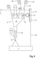
- FIG. 1 shows a simplified schematic diagram of a ship or floating crane 2 designed with a device according to the invention for heave compensation (HCS) 1, via which a load L is to be placed on another ship or on the seabed 4 or a platform anchored thereon.
- the device 1 motion compensation device, HCS
- a loading crane is mounted on the indicated floating crane 2, which has, in a manner known per se, a stationary roller or a plurality of stationary rollers 14 (discs) and a movable roller or a plurality of movable rollers (disks) 16, which together with a support cable 18 form a pulley 20.
- the movable rollers 16 (loose part) are mounted on a roller block 22.
- the support cable 18, which is fixed at one end to the deck, can be retrieved or lowered/lowered by means of a winch 21 of the loading crane 10 in order to raise or lower the load L.
- the power of the winch 21 is then translated accordingly via the pulley 20.
- a passive hydraulic cylinder 24 is attached to the roller block 22, which is designed as a synchronous cylinder.
- a piston 26 divides the hydraulic cylinder 24 into a pressure chamber 28 effective in the support direction and a pressure chamber 30 effective in the lowering direction.
- the pressure chamber 28 is connected to a hydropneumatic storage unit 32, which can be designed as usual as a hydropneumatic piston accumulator with one or more downstream gas bottles and through which the pressure chamber 28 is subjected to a preload pressure.
- the force resulting from this preload corresponds to approximately 110% of the load L to be moved. This load L is thus overcompensated, so that the load L is raised solely by the effect of the compensation device 6.
- the pressure chamber 28 and the hydropneumatic storage unit 32 form a type of gas spring.
- the hydraulic cylinder 24 is designed as a synchronous cylinder.
- a piston rod 34 on the load side in FIG. 1 carries the load L, which is attached to the piston rod 34, for example via a crane hook or the like.
- the other, in figure 1 upper piston rod 36 carries at its end section a console 38, on which a traction device, for example a winch cable 40 or a chain of the active compensation unit 8, engages. Since the piston rod 36 has the same diameter as the piston rod 34, no compensation is necessary due to the ambient pressure increasing with water depth.
- the winch cable 40 engages the console 38 in the lowering direction and is deflected by means of a deflection roller 42 in the direction of an active winch 44 of the active compensation unit 8 located on the deck of the floating crane 2.
- a deflection roller 42 In the area in which the winch cable 40 is in active engagement with the deflection roller 42, it can be designed as a chain, toothed belt or other tensile and wear-resistant traction device.
- the deflection roller 42 is in Figure 1 illustrated embodiment mounted on the hydraulic cylinder 24 or on the roller block 22.
- the active winch 44 in order to hold the piston 26 and the load in a fixed position relative to the roller block 22 or to lower the load L relative to the roller block 22 and thus to extend the piston rod 34, the active winch 44 must be controlled in such a way that the overcompensation via the Passive compensation device is compensated (when holding) or overdriven (when lowering). In the exemplary embodiment shown, the active compensation unit thus pushes the load L in the lowering direction.
- the hydraulic cylinder 24 of the passive compensation device 6 is designed as a differential cylinder and only has the piston rod 34.
- the pressure chamber 30 can, for example, be assigned a device for compensating for the water depth.
- the pressure chamber 30 can also be connected to a pressure medium compensation tank.
- the active compensation unit 8 has, as in the exemplary embodiment Figure 1 again a deflection roller 42, over which a winch cable 40 (or other traction device) is guided, which engages a console 38.
- the console 38 is not attached to the piston 26 but to a push rod 46. This push rod 46 engages parallel to the piston rod 28 on the crane hook on which the load hangs.
- the push rod 46 is axially displaceable in the vertical direction on a guide 48, which in turn is fixed to the hydraulic cylinder 24 or to the roller block 22.
- the push rod 46 is shown as shown Figure 2 actively applied downwards with a force.
- This force must be greater than the overcompensation via the passive compensation device 6 in order to be able to hold or lower the load L relative to the roller block 22.
- the active compensation unit 8 acts hydraulically/pneumatically on the hydraulic cylinder 24 of the passive compensation device 6.
- a push cylinder 50 is provided parallel to the hydraulic cylinder 24, which is connected to the hydraulic cylinder 24, for example via a bridge 52.
- the push cylinder 50 is designed as a differential cylinder and has an active piston 54 and an active piston rod 56, which is always subjected to tension and on which a winch cable 40 of the active winch 44 engages.
- the active piston 54 delimits an active pressure chamber 58 on the piston rod side, which is also connected to the pressure chamber 30 of the pressure chamber 30 via a connecting line 60 or a channel formed in the bridge 52 as a differential cylinder executed hydraulic cylinder 24 is connected.
- the active piston rod 56 When retrieving the winch cable 40, the active piston rod 56 is extended and corresponding pressure medium is pushed from the active pressure chamber 58 via the connecting line 60 into the pressure chamber 30, so that the load L against its preload/overcompensation in the pressure chamber 28 to compensate for swell or the like relative to the roller block 22 is lowered.
- an expansion tank (not shown) can be assigned to it.
- Figure 4 shows an exemplary embodiment with a compared to the exemplary embodiment Figure 1 somewhat more complex active compensation unit 8, via which the movements of the load L relative to the roller block 22 in the raising and lowering directions can be actively controlled.
- the passive compensation device 6 shown has a similar structure to that in the exemplary embodiment Figure 1 an active winch 44, the winch rope 40 of which is initially deflected via the deflection roller 42, which in this exemplary embodiment is mounted on the roller block 22, on which the loose rollers 16 are also arranged.
- the winch cable 40 does not end at a component located in the area of the roller block 22, as in the previously described exemplary embodiments, but extends away from the deflection roller 42 to a further active winch 64, which, like the active winch 44, can also be controlled via the control unit, not shown to pull in or lower the winch rope 40.
- An angled coupling rod 68 engages on the strand 66 extending between the further active winch 64 and the deflection roller 42. This is connected to the winch cable 40, for example via a clamp.
- This coupling rod 68 then engages with a horizontal leg 70 on the piston rod 36 of the piston 26.
- the hydraulic cylinder 24 is the same as in the exemplary embodiment Figure 1 designed as a synchronous cylinder.
- the load L can be lowered relative to the roller block 22 be that the winch rope 40 is unwound from one active winch 64 and wound onto the other active winch 44 or by the active winches 44, 64 being operated in the same direction with a speed difference.
- the latter is the case, for example, when the load L is lowered via the lifting device and the push rod 68 is nevertheless acted upon against the supporting force of the passive compensation device 6, with both active winches 44, 64 being controlled accordingly via the control unit, not shown.
- the push rod 68 can be acted upon in the lifting direction by reversing the active winches 44, 64, so that - as with conventional systems - it also acts in the supporting direction.
- the exemplary embodiment according to Figure 5 is a variant of the exemplary embodiment according to Figure 4 .
- the hydraulic cylinder 24 is as in the exemplary embodiment Figure 2 designed as a differential cylinder 24, with the load L acting on the piston rod 34.
- a push rod 46 is mounted so that it can move in the axial direction via a guide 48, which engages the crane hook on which the load L hangs, bypassing the hydraulic cylinder 24.
- the push rod 46 is actuated in accordance with the exemplary embodiment Figure 4 .
- two active winches 44, 64 are provided, between which a traction means, for example the winch cable 40, which is deflected over the deflection roller 42, extends.
- the coupling rod 68 which is connected to the strand 66 in a tension-proof manner, engages directly on the push rod 46, so that the overcompensation by appropriately controlling the active winches 44, 64 allows the push rod 46 to be extended against the preload acting on the load L in order to increase the load L relative to the roller block 22 to lower.
- FIG. 6 shows another exemplary embodiment based on the Figures 4 and 5 explained concept. Also with the in Figure 6
- the hydraulic cylinder 24 is designed as a differential cylinder.
- the active compensation unit 8 in turn has two active winches 44, 64 for retrieving or rewinding (unwinding, winding up) the winch rope 40 or other traction means.
- the winch cable 40 is deflected via a deflection roller 42 mounted on the roller block 22.
- This deflection roller 42 drives a pinion 72 via a chain, a toothed belt, a shaft or the like, which in turn meshes with a toothed rack 74, which also has a pressure-resistant rod 76 connected to the load L.
- the direction of rotation of the pinion 72 can be selected and the load L can either be lowered relative to the roller block 22 against the overcompensation or raised to support the passive compensation device 6 via the operative connection with the rack 74 and the rod 76 become.
- gear transmission with a pinion 72 and a rack 74
- another transmission can also be used.
- the actuators are designed as winches (winch 21, active winches 44, 64).
- other actuators such as linear drives or the like, can also be used instead of such winches.
- the winch cable 40 can be designed as a chain or other wear-resistant traction device in the area of the deflection.
- the section to be wound onto the winches can also be made of high-strength plastic, for example Dyneema ® .
- the maximum cable length wound on the active winches 44 and 64 corresponds approximately only to the maximum lift of the load, so that the active actuators can be designed to be relatively small.
- the active one Compensation unit can be retrofitted with little effort because the active and passive systems can essentially be operated independently of one another.
- the application of the device is not limited to compensating for movements caused by sea conditions but is generally applicable where relative movements of a load caused by external circumstances are to be compensated for.
- the active compensation unit can also be designed as a mobile solution.
- the pressure in the pressure chamber 28 is so great that the force generated by this pressure on the piston 26 overcompensates for the weight of the load L.
- the force is 10 percent greater than the weight.
- the piston rod 34 would therefore retract if the active compensation unit 8 on the crane hook did not exert a force in the direction of lowering the load, which is equal to the proportion of the force generated by the pressure in the pressure chamber 28 that goes beyond the weight force.
- the piston 26 is located approximately in the middle of the hydraulic cylinder 24, so that it can make the same stroke in the opposite direction.
- the winch 44 or the winches 44 and 64 are controlled so that the deflection roller 42 follows the movement.
- the force generated by the active compensation unit is increased, so that the sum of the weight of the load and the force generated by the active compensation device 8 outweighs the force generated by the pressure prevailing in the pressure chamber 28 and the piston rod 34 extends.
- the movement of the load is not affected by the movement of the ship's crane. If the ship's crane lowers due to a wave, the force generated by the active compensation unit is reduced, so that the sum of the weight of the load and the force generated by the active compensation device 8 becomes smaller than the force generated by the pressure prevailing in the pressure chamber 28 and the piston rod 34 retracts. Again, the movement of the load is not affected by the movement of the ship's crane.
Landscapes
- Engineering & Computer Science (AREA)
- Mechanical Engineering (AREA)
- Jib Cranes (AREA)
Claims (12)
- Appareil pour le levage, l'abaissement ou le maintien d'une charge (L) comportant un appareil de compensation pour l'équilibrage de mouvements relatifs de la charge (L) provoqués en particulier par la houle par rapport à une position cible, dans lequel la charge (L) peut être déplacée par un appareil de levage en direction de la position cible ou en s'éloignant de celle-ci et un appareil de compensation passive (6) est associé à l'appareil de levage, qui soutient le poids de la charge (L), dans lequel une unité de compensation active (8) est prévue, qui peut être commandée en fonction d'un mouvement relatif de la charge (L) ou d'une force active, dans lequel l'appareil de compensation passive (6) soutient le poids de la charge (L) au moins à 100 pour cent et dans lequel l'unité de compensation active (8) agit à l'opposé de la direction de soutien sur la charge (L), dans lequel l'appareil de compensation passive (6) est sollicité avec une précontrainte de telle sorte que la force de soutien résultant de la précontrainte est supérieure à la charge (L) ou à la force active, dans lequel l'appareil de compensation passive (6) dispose d'un vérin hydraulique (24) comportant un piston (26), qui délimite une chambre de pression (28) agissant dans la direction de soutien, qui est en liaison active avec une unité de stockage hydropneumatique (32), caractérisé en ce que l'unité de compensation active (8) dispose d'un treuil actif (44, 64), dont le câble de treuil (40) agit directement ou indirectement sur la charge (L) par l'intermédiaire du vérin hydraulique (24) ou en contournant le vérin hydraulique (24).
- Appareil selon la revendication 1, dans lequel le câble de treuil (40) est dévié par une poulie de renvoi (42).
- Appareil selon la revendication 2, dans lequel la poulie de renvoi (42) est montée sur le vérin hydraulique (24) ou sur un bloc à rouleaux (22) portant le vérin hydraulique (24).
- Appareil selon la revendication 2 ou 3, dans lequel le câble de treuil (40) agit sur une tige de pression (46) qui agit sur la charge (L), qui est guidée de manière coulissante sur le vérin hydraulique (24) ou sur le bloc de rouleaux (22).
- Appareil selon la revendication 3, dans lequel le câble de treuil (40) est guidé du bloc de renvoi (42) vers un autre treuil actif (64).
- Appareil selon la revendication 5, dans lequel dans une section de câble entre la poulie de renvoi (42) et un des treuils actifs (44, 64) une barre d'accouplement (68) agit sur le câble de treuil (40).
- Appareil selon la revendication 6, dans lequel la barre d'accouplement (68) est reliée au piston (26) du vérin hydraulique (24).
- Appareil selon la revendication 6, dans lequel la barre d'accouplement (68) agit sur une tige de pression (46) reliée à la charge (L), qui est guidée sur le vérin hydraulique (24) ou sur un bloc de rouleaux (22).
- Appareil selon la revendication 5, dans lequel la poulie de renvoi (42) entraîne un pignon (72), qui s'engrène avec un élément d'entraînement, de préférence une crémaillère (74), agissant directement ou indirectement sur la charge (L).
- Appareil selon la revendication 1, dans lequel le câble de treuil (40) agit sur un piston actif (54) d'un cylindre de poussée (50), dans lequel le piston actif (54) délimite une chambre de pression active (58), qui est en liaison de fluide sous pression avec une chambre de pression (30) du vérin hydraulique (24) agissant à l'opposé de la direction de soutien.
- Appareil selon la revendication 10, dans lequel le cylindre actif (50) et le vérin hydraulique (24) sont reliés l'un à l'autre.
- Appareil selon l'une des revendications précédentes, dans lequel la force de soutien résultant de la précontrainte est d'environ 105 % à 150 %, de préférence environ 110 % de la charge (L) ou de la force active.
Applications Claiming Priority (1)
| Application Number | Priority Date | Filing Date | Title |
|---|---|---|---|
| DE102016216260 | 2016-08-30 |
Publications (3)
| Publication Number | Publication Date |
|---|---|
| EP3290384A1 EP3290384A1 (fr) | 2018-03-07 |
| EP3290384C0 EP3290384C0 (fr) | 2024-03-13 |
| EP3290384B1 true EP3290384B1 (fr) | 2024-03-13 |
Family
ID=58672326
Family Applications (1)
| Application Number | Title | Priority Date | Filing Date |
|---|---|---|---|
| EP17167050.8A Active EP3290384B1 (fr) | 2016-08-30 | 2017-04-19 | Dispositif destiné à lever, abaisser ou maintenir une charge |
Country Status (2)
| Country | Link |
|---|---|
| EP (1) | EP3290384B1 (fr) |
| DE (1) | DE102017206595A1 (fr) |
Cited By (1)
| Publication number | Priority date | Publication date | Assignee | Title |
|---|---|---|---|---|
| EP3420177A4 (fr) * | 2016-02-22 | 2019-10-23 | Safelink AS | Compensateur de pilonnement actif mobile |
Families Citing this family (2)
| Publication number | Priority date | Publication date | Assignee | Title |
|---|---|---|---|---|
| NL2035273B1 (en) * | 2023-07-05 | 2025-01-13 | Itrec Bv | Offshore crane with heave compensator |
| CN120697930B (zh) * | 2025-06-26 | 2026-02-24 | 中国船舶集团有限公司第七一九研究所 | 潜水用升沉补偿方法及电子设备 |
Citations (3)
| Publication number | Priority date | Publication date | Assignee | Title |
|---|---|---|---|---|
| US3912227A (en) * | 1973-10-17 | 1975-10-14 | Drilling Syst Int | Motion compensation and/or weight control system |
| WO2011034422A2 (fr) * | 2009-09-18 | 2011-03-24 | Itrec B.V. | Dispositif de levage |
| WO2018151593A1 (fr) * | 2017-02-14 | 2018-08-23 | Itrec B.V. | Système de compensation de mouvement de pilonnement |
Family Cites Families (8)
| Publication number | Priority date | Publication date | Assignee | Title |
|---|---|---|---|---|
| US4021019A (en) | 1975-03-24 | 1977-05-03 | British Columbia Research Council | Heave compensating cranes |
| FR2344490A1 (fr) | 1976-03-18 | 1977-10-14 | Elf Aquitaine | Dispositif de compensation des variations de distance entre un objet flottant sur l'eau et le fond de celle-ci |
| FR2383876A2 (fr) * | 1977-03-17 | 1978-10-13 | Elf Aquitaine | Dispositif de compensation des variations de distance entre un objet flottant sur l'eau et le fond de celle-ci |
| DE102005058952A1 (de) | 2005-04-04 | 2006-10-05 | Bosch Rexroth Ag | Hydraulische Seegangskompensationseinrichtung |
| US7934561B2 (en) | 2007-04-10 | 2011-05-03 | Intermoor, Inc. | Depth compensated subsea passive heave compensator |
| DK2896589T3 (en) | 2014-01-17 | 2017-01-23 | Sal Heavy Lift Gmbh | Method and apparatus. |
| DE102015225936A1 (de) | 2015-01-14 | 2016-07-14 | Robert Bosch Gmbh | Einrichtung zum Heben, Senken oder Halten einer Last und Verfahren zur Ansteuerung einer derartigen Einrichtung |
| DE102015225931A1 (de) | 2015-12-18 | 2017-06-22 | Alexander Vogler | Leuchtvorrichtung für ein Fahrzeug |
-
2017
- 2017-04-19 EP EP17167050.8A patent/EP3290384B1/fr active Active
- 2017-04-19 DE DE102017206595.8A patent/DE102017206595A1/de active Pending
Patent Citations (3)
| Publication number | Priority date | Publication date | Assignee | Title |
|---|---|---|---|---|
| US3912227A (en) * | 1973-10-17 | 1975-10-14 | Drilling Syst Int | Motion compensation and/or weight control system |
| WO2011034422A2 (fr) * | 2009-09-18 | 2011-03-24 | Itrec B.V. | Dispositif de levage |
| WO2018151593A1 (fr) * | 2017-02-14 | 2018-08-23 | Itrec B.V. | Système de compensation de mouvement de pilonnement |
Cited By (1)
| Publication number | Priority date | Publication date | Assignee | Title |
|---|---|---|---|---|
| EP3420177A4 (fr) * | 2016-02-22 | 2019-10-23 | Safelink AS | Compensateur de pilonnement actif mobile |
Also Published As
| Publication number | Publication date |
|---|---|
| EP3290384C0 (fr) | 2024-03-13 |
| EP3290384A1 (fr) | 2018-03-07 |
| DE102017206595A1 (de) | 2018-03-01 |
Similar Documents
| Publication | Publication Date | Title |
|---|---|---|
| AT520091B1 (de) | Transporteinrichtung für einen Kran | |
| EP3016901B1 (fr) | Grue a tour et procédé de montage d'une pale de rotor d'eolienne | |
| DE2143943A1 (de) | Ausgleichsvorrichtung zum Steuern und Aufrechterhalten einer vorbestimmten Spannung in einem Strang | |
| EP3045416A1 (fr) | Dispositif de levage, d'abaissement ou de retenue d'une charge et procede de commande d'un tel dispositif | |
| DE2448813A1 (de) | Verfahren und system zur bewegungskompensation und/oder gewichtssteuerung fuer eine lasttragende vorrichtung, insbesondere eine erdbohrvorrichtung | |
| DE2143944A1 (de) | Ausgleichsvorrichtung | |
| EP3290384B1 (fr) | Dispositif destiné à lever, abaisser ou maintenir une charge | |
| DE102014215313B4 (de) | Seegangskompensationseinrichtung | |
| WO2007115564A1 (fr) | Table a parallelogramme articule | |
| DE102005058952A1 (de) | Hydraulische Seegangskompensationseinrichtung | |
| EP3243735B1 (fr) | Dispositif compensatoire d'état de la mer | |
| DE2120766A1 (de) | Stabilisierte Lastwindeneinrichtung | |
| DE2018926A1 (de) | Verfahren und Vorrichtung zum Verhindern des Ausknickens der Stößel mehrteiliger ausfahrbarer Ausleger | |
| EP3290382B1 (fr) | Dispositif destiné à lever, abaisser ou maintenir une charge | |
| EP3590881A1 (fr) | Dispositif de transport | |
| EP3290383B1 (fr) | Dispositif destiné à lever, abaisser ou maintenir une charge | |
| DE3016156C2 (de) | Hubgerüst mit wenigstens einem ausfahrbaren Teil und einem Lastträger zur Handhabung der Last | |
| DE102020113081A1 (de) | Greifvorrichtung mit Schließantrieb durch übersetzte Kraftvervielfältigung | |
| DE2433015C3 (de) | Hebevorrichtung mit einem vertikal festlegbaren Mast | |
| DE102017207948A1 (de) | Windenvorrichtung | |
| DE602004005458T2 (de) | Hebemechanismus | |
| DE3443191C2 (de) | Stoßschutzeinrichtung für das Abbremsen von Schiffen in Schleusenanlagen | |
| DE2416968A1 (de) | Stosschutzeinrichtung fuer schleusentore | |
| DE20319073U1 (de) | Kran, insbesondere Mobilkran | |
| EP3539917A1 (fr) | Machine de transport à tambour |
Legal Events
| Date | Code | Title | Description |
|---|---|---|---|
| PUAI | Public reference made under article 153(3) epc to a published international application that has entered the european phase |
Free format text: ORIGINAL CODE: 0009012 |
|
| STAA | Information on the status of an ep patent application or granted ep patent |
Free format text: STATUS: THE APPLICATION HAS BEEN PUBLISHED |
|
| AK | Designated contracting states |
Kind code of ref document: A1 Designated state(s): AL AT BE BG CH CY CZ DE DK EE ES FI FR GB GR HR HU IE IS IT LI LT LU LV MC MK MT NL NO PL PT RO RS SE SI SK SM TR |
|
| AX | Request for extension of the european patent |
Extension state: BA ME |
|
| STAA | Information on the status of an ep patent application or granted ep patent |
Free format text: STATUS: REQUEST FOR EXAMINATION WAS MADE |
|
| 17P | Request for examination filed |
Effective date: 20180907 |
|
| RBV | Designated contracting states (corrected) |
Designated state(s): AL AT BE BG CH CY CZ DE DK EE ES FI FR GB GR HR HU IE IS IT LI LT LU LV MC MK MT NL NO PL PT RO RS SE SI SK SM TR |
|
| RAP1 | Party data changed (applicant data changed or rights of an application transferred) |
Owner name: ROBERT BOSCH GMBH |
|
| STAA | Information on the status of an ep patent application or granted ep patent |
Free format text: STATUS: EXAMINATION IS IN PROGRESS |
|
| 17Q | First examination report despatched |
Effective date: 20200729 |
|
| TPAC | Observations filed by third parties |
Free format text: ORIGINAL CODE: EPIDOSNTIPA |
|
| RAP1 | Party data changed (applicant data changed or rights of an application transferred) |
Owner name: VAN HALTEREN TECHNOLOGIES BOXTEL B.V. |
|
| TPAC | Observations filed by third parties |
Free format text: ORIGINAL CODE: EPIDOSNTIPA |
|
| GRAP | Despatch of communication of intention to grant a patent |
Free format text: ORIGINAL CODE: EPIDOSNIGR1 |
|
| STAA | Information on the status of an ep patent application or granted ep patent |
Free format text: STATUS: GRANT OF PATENT IS INTENDED |
|
| INTG | Intention to grant announced |
Effective date: 20231019 |
|
| GRAS | Grant fee paid |
Free format text: ORIGINAL CODE: EPIDOSNIGR3 |
|
| GRAA | (expected) grant |
Free format text: ORIGINAL CODE: 0009210 |
|
| STAA | Information on the status of an ep patent application or granted ep patent |
Free format text: STATUS: THE PATENT HAS BEEN GRANTED |
|
| AK | Designated contracting states |
Kind code of ref document: B1 Designated state(s): AL AT BE BG CH CY CZ DE DK EE ES FI FR GB GR HR HU IE IS IT LI LT LU LV MC MK MT NL NO PL PT RO RS SE SI SK SM TR |
|
| REG | Reference to a national code |
Ref country code: GB Ref legal event code: FG4D Free format text: NOT ENGLISH |
|
| REG | Reference to a national code |
Ref country code: CH Ref legal event code: EP |
|
| REG | Reference to a national code |
Ref country code: DE Ref legal event code: R096 Ref document number: 502017015918 Country of ref document: DE |
|
| REG | Reference to a national code |
Ref country code: IE Ref legal event code: FG4D Free format text: LANGUAGE OF EP DOCUMENT: GERMAN |
|
| U01 | Request for unitary effect filed |
Effective date: 20240412 |
|
| U07 | Unitary effect registered |
Designated state(s): AT BE BG DE DK EE FI FR IT LT LU LV MT NL PT SE SI Effective date: 20240419 |
|
| PG25 | Lapsed in a contracting state [announced via postgrant information from national office to epo] |
Ref country code: GR Free format text: LAPSE BECAUSE OF FAILURE TO SUBMIT A TRANSLATION OF THE DESCRIPTION OR TO PAY THE FEE WITHIN THE PRESCRIBED TIME-LIMIT Effective date: 20240614 |
|
| PG25 | Lapsed in a contracting state [announced via postgrant information from national office to epo] |
Ref country code: RS Free format text: LAPSE BECAUSE OF FAILURE TO SUBMIT A TRANSLATION OF THE DESCRIPTION OR TO PAY THE FEE WITHIN THE PRESCRIBED TIME-LIMIT Effective date: 20240613 Ref country code: HR Free format text: LAPSE BECAUSE OF FAILURE TO SUBMIT A TRANSLATION OF THE DESCRIPTION OR TO PAY THE FEE WITHIN THE PRESCRIBED TIME-LIMIT Effective date: 20240313 |
|
| PG25 | Lapsed in a contracting state [announced via postgrant information from national office to epo] |
Ref country code: ES Free format text: LAPSE BECAUSE OF FAILURE TO SUBMIT A TRANSLATION OF THE DESCRIPTION OR TO PAY THE FEE WITHIN THE PRESCRIBED TIME-LIMIT Effective date: 20240313 |
|
| PG25 | Lapsed in a contracting state [announced via postgrant information from national office to epo] |
Ref country code: RS Free format text: LAPSE BECAUSE OF FAILURE TO SUBMIT A TRANSLATION OF THE DESCRIPTION OR TO PAY THE FEE WITHIN THE PRESCRIBED TIME-LIMIT Effective date: 20240613 Ref country code: HR Free format text: LAPSE BECAUSE OF FAILURE TO SUBMIT A TRANSLATION OF THE DESCRIPTION OR TO PAY THE FEE WITHIN THE PRESCRIBED TIME-LIMIT Effective date: 20240313 Ref country code: GR Free format text: LAPSE BECAUSE OF FAILURE TO SUBMIT A TRANSLATION OF THE DESCRIPTION OR TO PAY THE FEE WITHIN THE PRESCRIBED TIME-LIMIT Effective date: 20240614 Ref country code: ES Free format text: LAPSE BECAUSE OF FAILURE TO SUBMIT A TRANSLATION OF THE DESCRIPTION OR TO PAY THE FEE WITHIN THE PRESCRIBED TIME-LIMIT Effective date: 20240313 |
|
| PG25 | Lapsed in a contracting state [announced via postgrant information from national office to epo] |
Ref country code: IS Free format text: LAPSE BECAUSE OF FAILURE TO SUBMIT A TRANSLATION OF THE DESCRIPTION OR TO PAY THE FEE WITHIN THE PRESCRIBED TIME-LIMIT Effective date: 20240713 |
|
| PG25 | Lapsed in a contracting state [announced via postgrant information from national office to epo] |
Ref country code: SM Free format text: LAPSE BECAUSE OF FAILURE TO SUBMIT A TRANSLATION OF THE DESCRIPTION OR TO PAY THE FEE WITHIN THE PRESCRIBED TIME-LIMIT Effective date: 20240313 |
|
| PG25 | Lapsed in a contracting state [announced via postgrant information from national office to epo] |
Ref country code: CZ Free format text: LAPSE BECAUSE OF FAILURE TO SUBMIT A TRANSLATION OF THE DESCRIPTION OR TO PAY THE FEE WITHIN THE PRESCRIBED TIME-LIMIT Effective date: 20240313 |
|
| PG25 | Lapsed in a contracting state [announced via postgrant information from national office to epo] |
Ref country code: PL Free format text: LAPSE BECAUSE OF FAILURE TO SUBMIT A TRANSLATION OF THE DESCRIPTION OR TO PAY THE FEE WITHIN THE PRESCRIBED TIME-LIMIT Effective date: 20240313 |
|
| PG25 | Lapsed in a contracting state [announced via postgrant information from national office to epo] |
Ref country code: SK Free format text: LAPSE BECAUSE OF FAILURE TO SUBMIT A TRANSLATION OF THE DESCRIPTION OR TO PAY THE FEE WITHIN THE PRESCRIBED TIME-LIMIT Effective date: 20240313 |
|
| PG25 | Lapsed in a contracting state [announced via postgrant information from national office to epo] |
Ref country code: SM Free format text: LAPSE BECAUSE OF FAILURE TO SUBMIT A TRANSLATION OF THE DESCRIPTION OR TO PAY THE FEE WITHIN THE PRESCRIBED TIME-LIMIT Effective date: 20240313 Ref country code: SK Free format text: LAPSE BECAUSE OF FAILURE TO SUBMIT A TRANSLATION OF THE DESCRIPTION OR TO PAY THE FEE WITHIN THE PRESCRIBED TIME-LIMIT Effective date: 20240313 Ref country code: RO Free format text: LAPSE BECAUSE OF FAILURE TO SUBMIT A TRANSLATION OF THE DESCRIPTION OR TO PAY THE FEE WITHIN THE PRESCRIBED TIME-LIMIT Effective date: 20240313 Ref country code: PL Free format text: LAPSE BECAUSE OF FAILURE TO SUBMIT A TRANSLATION OF THE DESCRIPTION OR TO PAY THE FEE WITHIN THE PRESCRIBED TIME-LIMIT Effective date: 20240313 Ref country code: IS Free format text: LAPSE BECAUSE OF FAILURE TO SUBMIT A TRANSLATION OF THE DESCRIPTION OR TO PAY THE FEE WITHIN THE PRESCRIBED TIME-LIMIT Effective date: 20240713 Ref country code: CZ Free format text: LAPSE BECAUSE OF FAILURE TO SUBMIT A TRANSLATION OF THE DESCRIPTION OR TO PAY THE FEE WITHIN THE PRESCRIBED TIME-LIMIT Effective date: 20240313 |
|
| REG | Reference to a national code |
Ref country code: CH Ref legal event code: PL |
|
| REG | Reference to a national code |
Ref country code: DE Ref legal event code: R097 Ref document number: 502017015918 Country of ref document: DE |
|
| U90 | Renewal fees not paid: noting of loss of rights |
Free format text: RENEWAL FEE NOT PAID FOR YEAR 08 Effective date: 20241118 |
|
| PG25 | Lapsed in a contracting state [announced via postgrant information from national office to epo] |
Ref country code: MC Free format text: LAPSE BECAUSE OF FAILURE TO SUBMIT A TRANSLATION OF THE DESCRIPTION OR TO PAY THE FEE WITHIN THE PRESCRIBED TIME-LIMIT Effective date: 20240313 |
|
| PLBE | No opposition filed within time limit |
Free format text: ORIGINAL CODE: 0009261 |
|
| STAA | Information on the status of an ep patent application or granted ep patent |
Free format text: STATUS: NO OPPOSITION FILED WITHIN TIME LIMIT |
|
| PG25 | Lapsed in a contracting state [announced via postgrant information from national office to epo] |
Ref country code: MC Free format text: LAPSE BECAUSE OF FAILURE TO SUBMIT A TRANSLATION OF THE DESCRIPTION OR TO PAY THE FEE WITHIN THE PRESCRIBED TIME-LIMIT Effective date: 20240313 Ref country code: CH Free format text: LAPSE BECAUSE OF NON-PAYMENT OF DUE FEES Effective date: 20240430 |
|
| U50 | Request for re-establishment of rights filed [unitary effect] |
Free format text: RE-ESTABLISHMENT OF RIGHTS REQUESTED DUE TO A NOTIFICATION OF LAPSE Effective date: 20241226 |
|
| 26N | No opposition filed |
Effective date: 20241216 |
|
| GBPC | Gb: european patent ceased through non-payment of renewal fee |
Effective date: 20240613 |
|
| PG25 | Lapsed in a contracting state [announced via postgrant information from national office to epo] |
Ref country code: IE Free format text: LAPSE BECAUSE OF NON-PAYMENT OF DUE FEES Effective date: 20240419 |
|
| PG25 | Lapsed in a contracting state [announced via postgrant information from national office to epo] |
Ref country code: GB Free format text: LAPSE BECAUSE OF NON-PAYMENT OF DUE FEES Effective date: 20240613 |
|
| U20 | Renewal fee for the european patent with unitary effect paid |
Year of fee payment: 9 Effective date: 20250417 |
|
| PGFP | Annual fee paid to national office [announced via postgrant information from national office to epo] |
Ref country code: NO Payment date: 20250422 Year of fee payment: 9 |
|
| U53 | Request for re-establishment of rights accepted [unitary effect] |
Effective date: 20250630 |
|
| PG25 | Lapsed in a contracting state [announced via postgrant information from national office to epo] |
Ref country code: CY Free format text: LAPSE BECAUSE OF FAILURE TO SUBMIT A TRANSLATION OF THE DESCRIPTION OR TO PAY THE FEE WITHIN THE PRESCRIBED TIME-LIMIT; INVALID AB INITIO Effective date: 20170419 |
|
| PG25 | Lapsed in a contracting state [announced via postgrant information from national office to epo] |
Ref country code: HU Free format text: LAPSE BECAUSE OF FAILURE TO SUBMIT A TRANSLATION OF THE DESCRIPTION OR TO PAY THE FEE WITHIN THE PRESCRIBED TIME-LIMIT; INVALID AB INITIO Effective date: 20170419 |
|
| U1N | Appointed representative for the unitary patent procedure changed after the registration of the unitary effect |
Representative=s name: NOVAGRAAF TECHNOLOGIES; FR |
|
| U20 | Renewal fee for the european patent with unitary effect paid |
Year of fee payment: 9 Effective date: 20250417 |