EP3290618A1 - Ensemble de tête de nivellement pour un socle de nivellement d'élévation, ledit socle de nivellement d'élévation et procédé de fabrication d'un socle de nivellement d'élévation - Google Patents
Ensemble de tête de nivellement pour un socle de nivellement d'élévation, ledit socle de nivellement d'élévation et procédé de fabrication d'un socle de nivellement d'élévation Download PDFInfo
- Publication number
- EP3290618A1 EP3290618A1 EP17173311.6A EP17173311A EP3290618A1 EP 3290618 A1 EP3290618 A1 EP 3290618A1 EP 17173311 A EP17173311 A EP 17173311A EP 3290618 A1 EP3290618 A1 EP 3290618A1
- Authority
- EP
- European Patent Office
- Prior art keywords
- head
- support
- cap
- threaded
- leveling
- Prior art date
- Legal status (The legal status is an assumption and is not a legal conclusion. Google has not performed a legal analysis and makes no representation as to the accuracy of the status listed.)
- Granted
Links
Images





Classifications
-
- E—FIXED CONSTRUCTIONS
- E04—BUILDING
- E04F—FINISHING WORK ON BUILDINGS, e.g. STAIRS, FLOORS
- E04F15/00—Flooring
- E04F15/02—Flooring or floor layers composed of a number of similar elements
- E04F15/024—Sectional false floors, e.g. computer floors
- E04F15/02447—Supporting structures
- E04F15/02464—Height adjustable elements for supporting the panels or a panel-supporting framework
- E04F15/0247—Screw jacks
- E04F15/02482—Screw jacks with a variable angle between panel and support
-
- E—FIXED CONSTRUCTIONS
- E04—BUILDING
- E04D—ROOF COVERINGS; SKY-LIGHTS; GUTTERS; ROOF-WORKING TOOLS
- E04D11/00—Roof covering, as far as not restricted to features covered by only one of groups E04D1/00 - E04D9/00; Roof covering in ways not provided for by groups E04D1/00 - E04D9/00, e.g. built-up roofs, elevated load-supporting roof coverings
- E04D11/005—Supports for elevated load-supporting roof coverings
- E04D11/007—Height-adjustable spacers
-
- E—FIXED CONSTRUCTIONS
- E04—BUILDING
- E04F—FINISHING WORK ON BUILDINGS, e.g. STAIRS, FLOORS
- E04F15/00—Flooring
- E04F15/02—Flooring or floor layers composed of a number of similar elements
- E04F15/02177—Floor elements for use at a specific location
- E04F15/02183—Floor elements for use at a specific location for outdoor use, e.g. in decks, patios, terraces, verandas or the like
-
- E—FIXED CONSTRUCTIONS
- E04—BUILDING
- E04F—FINISHING WORK ON BUILDINGS, e.g. STAIRS, FLOORS
- E04F15/00—Flooring
- E04F15/02—Flooring or floor layers composed of a number of similar elements
- E04F15/024—Sectional false floors, e.g. computer floors
- E04F15/02447—Supporting structures
- E04F15/02452—Details of junctions between the supporting structures and the panels or a panel-supporting framework
-
- E—FIXED CONSTRUCTIONS
- E04—BUILDING
- E04F—FINISHING WORK ON BUILDINGS, e.g. STAIRS, FLOORS
- E04F15/00—Flooring
- E04F15/02—Flooring or floor layers composed of a number of similar elements
- E04F15/024—Sectional false floors, e.g. computer floors
- E04F15/02447—Supporting structures
- E04F15/02464—Height adjustable elements for supporting the panels or a panel-supporting framework
- E04F15/0247—Screw jacks
-
- E—FIXED CONSTRUCTIONS
- E04—BUILDING
- E04F—FINISHING WORK ON BUILDINGS, e.g. STAIRS, FLOORS
- E04F15/00—Flooring
- E04F15/18—Separately-laid insulating layers; Other additional insulating measures; Floating floors
- E04F15/20—Separately-laid insulating layers; Other additional insulating measures; Floating floors for sound insulation
- E04F15/203—Separately-laid layers for sound insulation
-
- E—FIXED CONSTRUCTIONS
- E04—BUILDING
- E04F—FINISHING WORK ON BUILDINGS, e.g. STAIRS, FLOORS
- E04F15/00—Flooring
- E04F15/02—Flooring or floor layers composed of a number of similar elements
- E04F15/02044—Separate elements for fastening to an underlayer
- E04F2015/0205—Separate elements for fastening to an underlayer with load-supporting elongated furring elements between the flooring elements and the underlayer
- E04F2015/02066—Separate elements for fastening to an underlayer with load-supporting elongated furring elements between the flooring elements and the underlayer with additional fastening elements between furring elements and flooring elements
- E04F2015/02077—Separate elements for fastening to an underlayer with load-supporting elongated furring elements between the flooring elements and the underlayer with additional fastening elements between furring elements and flooring elements the additional fastening elements located in-between two adjacent flooring elements
- E04F2015/02094—Engaging side grooves running along the whole length of the flooring elements
Definitions
- the present invention relates to a leveling head assembly for an elevating leveling pedestal according to the opening part of claim 1, and a method of making such pedestal.
- the present invention relates generally to a device and a method for supporting a structure above a fixed surface, and more particularly, to a slope adjustable leveling head assembly and to a height and slope adjustable pedestal device made using a single length of unthreaded piping, the rotatable device base having minimal surface threading, and the device head able to be locked in a zero or non-zero slope for supporting a structure above a fixed surface, and the method of using such a device.
- US 5 301 480 appears to discloses a two-part tiltable support head comprising a lower part connectable to a cap and an upper part height adjustable relative to the lower part and comprising the supporting surface of the tiltable support head.
- the cap and the lower part respectively comprises a concave and a convex mating surface to allow slidable tilting repositioning of the lower part relative to the cap.
- a bolt is from below passed through an aperture with a relatively tight fit in the cap, an aperture with an enlarged diameter in the lower part, and a locking washer, and the bolt is secured by a nut.
- Elevated deck construction is gaining in popularity. Elevated deck floors often are made of deck-tiles, supported and connected by an array of pedestals.
- a deck tile typically consists of a 24"x24" square assembly of deck boards that are used primarily for patios and rooftop lounge areas. It is these deck-tiles that must be installed over and elevated up from a non-level roof surface to create a new, level walking deck surface, or optionally a sloped ramped surface.
- the object of the present invention is to provide an improved slope adjustable leveling head assembly, and this is obtained by the features of claim 1. Accordingly, the present inventive concept is to provide a slope adjustable leveling head assembly and height and slope adjustable pedestals that are strong, can be securely locked in a sloped or non-sloped position to securely maintain their height and slope, are cost effect, readily available, and easy to install. To make his concept a reality, the present Inventor developed a set of inventive principles to provide devices to support and attach a level walking surface over a first level or non-level sub-surface.
- pedestal elevation system for the installation of decking tiles over level or non-level surfaces.
- deck-tiles are typically a 24"x24" square assembly of deck boards.
- the pedestal elevation system as taught herein, securely connects such deck-tiles to each other as well as to the surface over which the deck-tiles are being installed and ensures that the newly installed deck-tiles, regardless of being installed either on a flat or a sloping surface of a pitched roof, present a level floor surface.
- the leveling, elevating pedestals include a rotatable means that consists of a threaded pedestal base that is rotatably attached to a threaded first end of a coupling, whereas the combination provides for each pedestal to be independently height adjustable, that is, each pedestal is easily adjusted to a specified height and can be rapidly and easily raised or lowered relative to the sub-surface for fine adjustments.
- a non-threaded second end of the coupling supports and is non-rotatably fastened to a non-threaded first end of a midsection of a predetermined length.
- a non-threaded second end of the midsection is not-rotatably attached to and supports a lockable, leveling (tilting) support-head, thus creating a pedestal that is able to compensate for any sloping or uneven surfaces over which deck-tiles are being installed as it is connecting deck-tiles to each other at their corner sites.
- This design provides for each pedestal to independently support each deck tile, as required (described in more detail below).
- One pedestal can provide support for and attach the intersecting corners of up to four deck-tiles.
- Each pedestal once completely installed and tightened in place, using a tightening bolt, secures the surface it is supporting. However, the pedestal can be easily and rapidly accessed to make any required adjustments by simply loosening the tightening bolt. Additionally, if desired, one skilled in the art would be able to adapt the pedestal to be used in its reverse orientation.
- each elevating pedestal has a platy locking element as part of the pedestal that, as the tiles are laid, is positioned within grooves pre-cut into the side of the deck-tiles.
- An example of such a locking element is a plastic coated metal washer with a distinctive property.
- the washer according to the inventive concept, is caused to have a narrow elongate slot emanating from the center of the washer through to its perimeter, thus having its length that of a radius of the washer. This slot is unlike the slot of any other similar device.
- pac-man like that is, a large-angle cut-out on each washer that can be described as a notch intersecting the washer perimeter to its center point of from approximately 105° to 130° wide.
- a notch of this width necessarily greatly decreases the surface area of the washer that, in turn, both greatly decreases the strength of the washer's hold-down capacity and provides much less surface to support each deck tile.
- getting the washers with the large-area slot into aligned engagement with the corners of each of the deck-tiles the pedestal is supporting requires time consuming adjustment of the washer to assure that as much surface of the washer as possible is supporting a deck-tile.
- the width of the elongate slot of the washer of the present invention is limited to being only wide enough to have the slot fit about the stem of the center tightening bolt, but not so wide as to fit about the head of the bolt.
- This design makes it possible for the washer to offer maximum hold-down strength and maximum surface area to more fully engage with the corner cut-outs of all four deck-tiles.
- the narrow elongate slot provides for the washer to be simply slid into, and out of, engagement with the deck-tiles.
- the tightening bolt locks the tiltable, leveling head either in a level horizontal position or in a tilted position, which is a unique feature.
- a locking washer (as discussed in more detail below) that serves to secure the tiltable leveling pedestal head in place.
- the present invention provides locking means for the leveling head to be a lockable stationary head by, in the example as shown, the use of a zero compensator washer (zeroing plug) that can rapidly and easily lock the leveling head to zero degrees.
- Designing the leveling head as a stationary head accurately zeroed provides the additional advantage of decreasing the installation time on top of level surfaces and, also, securely locks the head in the zero degree position, where currently available adjustable heads may easily slip out of the zero degree position.
- the zero compensator washer is removed, the head tilted to the required slope, and then locked into that position using the locking washer.
- the head is locked into position from the top side by using the center tightening bolt that is tightened into double-ended, multi-purpose bushing bolt mechanism.
- the tightening bolt fastener secures the multi-purpose bushing in place at the desired slope and also further secures the deck-tiles to the head.
- the leveling head also includes four tabs, each positioned at right angles to its neighbor tab, for the correct spacing of the elevated surface pieces being installed or, alternatively, the upper surface of the head is fitted with a joist support for the installation of elevated joists.
- the example of the present invention illustrated herein uses predetermined lengths of unthreaded PVC pipe as its midsection (also referred to as its main pedestal support section) and, as explained above, in conjunction with the threaded coupling section and its receiving base provides for final, small scale adjustments.
- the threaded coupling section rotatably connects the main pedestal support section to the threaded base.
- the base is internally threaded to accept the externally threaded portion of the coupling section.
- Many of the devices presently available rely on all of their pipe sections being threaded in order to achieve a desired height.
- the present invention does include a threaded section that is employed for final, fine adjustments, but the main elevating and support section of the pedestal relies on lengths of custom cut unthreaded PVC pipe, for several reasons.
- Unthreaded PVC pipe provides added strength and rigidity over the currently available systems, as threaded elongate sections tend to have less strength, be less rigid, and thus, be wobbly.
- unthreaded PVC pipe is readily available because such pipe can be found in most home stores ready to be cut to the desired length.
- the use of unthreaded PVC pipe also reduces cost, while creating a more rigid, stronger pedestal.
- the use of the unthreaded PVC pipe also improves installation time since it greatly reduces the number of threaded components which other devices require you to "gang" together to achieve the height required.
- a self-leveling head with a joist support that includes a slide feature to permit joists of different widths to be securely fit therein.
- the present inventive concept provides the principles that are used to make a leveling support pedestal system that is height adjustable and has a locking/titling leveling head.
- the pedestal levels, supports, and holds-down. That is, besides supporting and leveling the elevated surface that is being installed, the system is designed to secure the elevated surface against up-lift, from wind, for example.
- the inventive concept requires that the pedestal employs a single piece of non-threaded piping of predetermined length to provide the required elevated height.
- the example described herein uses inexpensive, readily available, strong and rigid PVC piping, although any piping that fills this need is contemplated within the scope of the invention.
- the principles provide for a leveling pedestal that is also able to secure the leveled, elevated surface deck-tiles, and the like, to a sub-floor that is at either a zero or a non-zero slope.
- rotatable means provided by the interaction of the base of the pedestal and a coupling section, provide for the pedestal to be raised or lowered vertically, as needed.
- the pedestal has a tilting head.
- the pedestal includes a zero compensator washer (zeroing plug) which locks the head of the pedestal to zero degrees.
- the zero compensator washer is removed so that the head can be tilted to the required slope of from zero degrees up to approximately seven degrees and then locked.
- the head is locked in position from the top of the pedestal by using the center tightening bolt/bushing-bolt mechanism as, in the example illustrated, comprises a washer having a narrow elongate slot, a bolt or the like, a double-ended multi-purpose bushing, and one or two locking washers.
- This fastener mechanism both secures the tiltable head in place at the desired slope and also secures the deck-tiles to the leveling head.
- the pedestal When the pedestal is used in this orientation, it is the tiltable head that is securely attached to the sub-surface, and it follows then that what was the bottom side of the base would, in the reverse position, act to support the surface that is being installed. If desired, the pedestal could still be tightened from the top simple by have the bolt's position changed to the base instead of the head.
- the head assembly includes a support-head having a support surface overlying and attached to a cap having a centered cap aperture therethrough.
- Either the support-head or the cap have a convex mating surface while the other has a concave mating surface providing for said support-head and said cap to be slidably re-positionable along their mating surfaces.
- the support-head is, thus, tiltable with respect to the cap and it will be shown, is lockable between zero degrees and approximately seven degrees of tilt.
- the support-head further includes a centered recess, referred to as a recess aperture, in which is a bottomed-well having a centered-bottom-well aperture.
- Detachably attaching the support-head to the cap is an assembly comprising a double-ended bushing having a first end and a second end, that is inserted, from the support-head's support surface down into the bottomed-well of the support-head, while from the bottom surface of the cap, an attachment device, such as a headed bolt, is inserted through an aperture of a locking washer and then up through an aperture in the cap to continue up through the bottom-well aperture until it securely engages with said second end of said double-ended bushing.
- the support-head can be securely locked at the desired angle, for example, by inserting a hex-wrench into the hex-accepting first end of the bushing aperture and turning the wrench until the desired amount of locking tightness is achieved effectively locking said support-head in a tilted position from zero to approximately seven degrees.
- the degrees of tilt may extend pass seven degrees to an amount measured in degree minutes.
- FIG. 1 a perspective view, illustrates one example of pedestal device 20.
- Pedestal device 20 comprises flanged cylindrical threaded base section 5 that in this example is rotatably attached to a threaded first end of, and supports, coupling 1 that, in turn, is connected to and supports a first end of a pre-determined length, non-threaded, midsection 2, which is the major, load-bearing support of pedestal 20.
- Midsection 2 offers greater strength and rigidity than currently available systems by being manufactured from a single, non-threaded section of PVC piping that is low cost, standard, and readily available.
- the increased rigidity and strength of the midsection 2 of the present invention is due to the fact that it consists of a single unit of non-threaded PVC pipe that is precut to the length required. This means that the walls of the midsection are not thinned by the incisions required by a threaded surface or by any connecting divisions that would be required for a multi-piece supporting midsection. To provide for height adjustment, presently available devices rely on multiple threaded units to build up to the height required. Both the connection areas between the various units and the incised-threaded walls of the units contribute to reducing the rigidity and strength of these supports, while increasing the overall unit cost.
- tiltable support-surface head 10 is illustrated in a tilted position.
- Cap 4 and tiltable support-surface head 10 together form leveling head assembly 30.
- the inventive principles provided by assembly 30 include the ability of the pedestal to be tilted to accommodate the requirements of the elevated surface being installed on a non-level sub-surface along with the ability of the head to be locked into any angle between the horizontal up to an angle of approximately seven degrees.
- the upper surface of head 10 supports spacing tabs 12 for the correct spacing of the elevated surface pieces being installed or, alternatively, the upper surface of head 10 supports a joist support for the installation of elevated joists, as illustrated in FIG.
- assembly 30 is provided with uplift protection washers 13 (illustrated in FIG. 2 ) to protect the elevated surface from wind uplift.
- Assembly 30 can be a stand-alone feature of the present invention in that it can be used as described, or can be used with other, different pedestals, such as with pedestals that depend on threaded intersections and midsections to obtain the pedestal height required.
- FIG. 2 a perspective, oblique view of pedestal 20, more clearly illustrates the top surface of tiltable support-head 10 and the top surface of base 5.
- fasteners 3 On the surface of tiltable support-head 10 are shown fasteners 3, spacing tabs 12, the top end of multi-purpose bushing 11, washer 13 having a slot that is narrow and elongate, and tightening bolt 15 going through the center of double-ended bushing 11 and narrowly slotted washer 13.
- attachment apertures 21 through the plate-like part of base 5 for attachment of the pedestal to the subsurface.
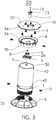
- FIG. 3 an exploded view of the pedestal
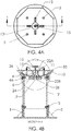
- FIG. 4B a cross-section view
- FIG. 4C illustrate the construction of pedestal 20.
- base 5 with its flanged base, is internally threaded to receive the threads on a first end of coupling 1.
- base 5 could have external threading, while the mating end of coupling 1 could be externally threaded.
- coupling 1 and base 5 each utilize six mating threads per inch to provide for fine-tuning the height of the unit. Even though the threading is kept to a minimum to enhance the strength of the base, in this example, base 5 is additionally strengthened by a series of spaced vertical flanges about the base.
- a second, not-threaded, end of coupling 1 is structured to couple with a first end of non-threaded midsection 2 of a predetermined length.
- the length of midsection 2 is determined by the specified height for each project.
- the first end (bottom end in this example) of midsection 2 serves as the male couple part and the second end (top end in this example) of coupling 1 serves as the female accepting couple part, but the inventive principles also contemplate the reverse coupling situation.
- fasteners 3 that in this case are Christmas tree or automotive type fasteners, but any fasteners that will work as intended are contemplated by the invention.
- the rotating, tiltable, support-head assembly 30 (better appreciated in FIG. 1 ) is designed to sit on, and to be attached to, the top rim 50 of midsection 2.
- the two basic components of adjustable leveling support-head assembly 30 comprise flanged cap 4 and tiltable support-head 10.
- Adjustable leveling support-head assembly 30 compensates for the difference in slope between the sub-surface and the surface being installed and supported by an array of pedestals 20.
- Downward facing surface 34 of tiltable support-head 10 in this example, is convex so as to be supported by and slidably re-positionable on the concave surface 36 of cap 4.
- the convex concave relationship could be reversed, that is cap 4 could have the convex surface and tiltable support-head 10 the concave shaped surface, to obtain the same result. Both of these relationships are contemplated by the inventive concept.
- the center area of tiltable support-head 10 is recessed forming bottomed-well 44 within recess aperture 22A. Through the bottom of well 44 there is centered well-bottom aperture 22B.
- Cap 4 has centered cap aperture 24 therethrough.
- tiltable support-head 10 To detachably, but securely, attach tiltable support-head 10 to cap 4, double-ended bushing 11 is placed inside bottomed-well 44 with headed-screw 7, or bolt, inserted up through aperture 26 of locking washer 6 to continue through washer 8 that is positioned within aperture 24 and to further continue through centered aperture 22B in the bottom of well 44 and into multi-use bushing 11.
- Adjustable leveling support-head assembly 30 is now ready to be placed about and secured to top-rim 50 of midsection 2. Adjustable leveling support-head 30 is secured to top-rim 50 of midsection 2 using fasteners 3 positioned through fastening apertures 43. Tiltable support-head 10 is now ready to be tilted to compensate for the angle of the sub-surface.
- Enlarged aperture diameters make possible the tilting of tiltable support-head 10 between 0 and approximately seven degrees.
- Tiltable support-head 10 is simply adjusted until it is set at the desired angle of between 0 and approximately seven degrees.
- Tiltable support-head 10 is then locked at the desired angle by inserting a hex-wrench into the, in this example, hex-accepting tightening bushing aperture and turning the wrench until the desired amount of locking tightness is achieved.
- the ability to both position and lock the tiltable head at any infinite position of between 0 and approximately seven degrees while having uplift protection is not, to the best of Applicant's knowledge, achievable by any other pedestal device.
- base 5 may be rotated to increase or decrease the height, as required.
- Tiltable support-head 10 can receive and support four spacer tabs 12 if desired for spacing of deck-tiles being installed.
- the means for receiving and supporting the spacer tabs are slots molded into tiltable support-head 10.
- head 10 is also available with the spacers molded as part of the head. In this case, when one or more such spacers are not required, a spacer may be removed by simply bending it about the scoring provided to easily and rapidly remove the spacer.
- FIG. 4A a plan view, illustrates how pedestal 20 of the present invention provides uplift protection to the surface being installed.
- Plastic-coated metal hold-down washer 13 having a narrow slot only as wide as tightening bolt 15 extending from the washer's center to its outer edge, provides a maximum amount of surface area that is to be inserted into the pre-cut notches of the surface material being installed. It is this surface area that provides the means to hold-down the surface being installed.
- washer 13 is a plastic-coated washer in the example illustrated, the washer can be of any material that provides the function required.
- the hold-down washer of the present invention does not need to be positionally rotated in order to have the washer engaging all four intersecting corners of the deck-tiles being installed, as is required by others who use a washer having a larger cut-out area.
- hold-down washer 13 is simply slid into place.
- Washer 13 is used in conjunction with headed tightening bolt 15 and double-ended bushing 11.
- First tightening bolt 15 is inserted into, in this example, a hex-accepting busing aperture and then the narrow elongate slot of washer 13 is positioned about bolt 15.
- a deck-tile panel is then placed on a pedestal that has been so equipped with washer 13 positioned about bolt 15, so that, as shown in FIGS.
- each deck-tile accepts approximately one-quarter of the of hold-down washer 13.
- a quick turn of a tightening tool about tightening bolt 15 assures that hold-down washer 13 is securely in place to hold down the deck-tiles, thus providing up-lift protection for the newly installed deck-tiles.
- tightening bolt 15 can be loosened and washer 13 can be slide out from the groove so that the deck-tiles can be removed and the work required performed beneath the raised floor. Once work is completed the deck-tiles can easily be reinstalled and the washer 13 slide back into place and tightened with tightening bolt 15. Illustrated in FIGS.
- fasteners 3 may be used for both positioning the elevated surface being installed and for providing added protection against up-lift of the elevated surface.
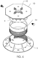
- FIG. 6 Clearly shown in FIG. 6 are four tabs 12 on tiltable support-head 10 that are used for spacing of the deck-tiles. These four tabs can be individually removed if not needed. Also illustrated in FIG. 6 is adapter 14. If a shorter stack height for the pedestal is required both midsection 2 and coupling 1 can be exchanged for adapter 14.
- raised deck floors are installed on an upper story, such as a roof top. This can happen often if entertainment space is needed but there is no land surface available, such as in a densely populated area. If the raised deck was installed over a living space where quiet was appreciated, the sound created by entertainment on the deck could be intrusive. In such an instance, it would be desirable to include sound insulation in the deck installation. With the present system this is easily accommodated by simply inserting a rubber sound-proofing pad between tiltable support-head 10 and the deck-tiles.
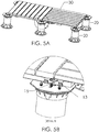
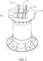
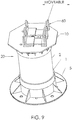
- tiltable support-head 10 to be designed with accessory joist support 60 as illustrated in FIGS. 7 - 10 .
- Tiltable support-head 10 is available with removable spacer tabs 12 or without spacer tabs. When molded with the spacer tabs scoring is placed on the spacers near the surface of head 10 for the purpose of removing any spacers not needed.
- tiltable support-head 10 can be used for additional purposes such as supporting joist support 60.
- Joist support 60 consists of the two part component as shown in the example illustrated in FIG. 7 .
- Stationary jaw 17 part of joist support 60 is attached to tiltable support-head 10 by securing bolt 19 through the attachment aperture of stationary jaw to double-ended, multi-purpose bushing 11.
- Moveable jaw 18 is slidably attached to stationary jaw 17 to accommodate joists of various widths.
- Stationary jaw 17 attachment part has multiple attachment apertures so it can be used with much wider or double joists in efforts to keep each joist centered over tiltable support-head 10 to evenly distribute weight over pedestal system.
- FIG. 8 illustrates the exploded parts of joist support 60.
- FIG. 7 illustrates accessory joist support 60 with moveable jaw 18 slid in toward stationary jaw 17, while
- FIG. 9 illustrates accessory joist support 60 with moveable jaw 18 slid a distance away from stationary jaw 17.
- FIG. 10 shows three pedestals 20 each being used in combination with joist support 60 according to the principles of the present invention to support
- a surface to be supported by pedestals according to the present invention is a raised flooring surface.
- said flooring surface further comprises are deck-tiles or deck-boards.
- a rubber sound-proofing pad is provided between said pedestal and the deck-tiles forming a sound barrier.
Landscapes
- Engineering & Computer Science (AREA)
- Architecture (AREA)
- Civil Engineering (AREA)
- Structural Engineering (AREA)
- General Engineering & Computer Science (AREA)
- Floor Finish (AREA)
- Soil Working Implements (AREA)
Applications Claiming Priority (3)
| Application Number | Priority Date | Filing Date | Title |
|---|---|---|---|
| US201361779085P | 2013-03-13 | 2013-03-13 | |
| EP14774538.4A EP2971402A4 (fr) | 2013-03-13 | 2014-03-13 | Système d'élévation à socle |
| PCT/US2014/025768 WO2014160076A1 (fr) | 2013-03-13 | 2014-03-13 | Système d'élévation à socle |
Related Parent Applications (1)
| Application Number | Title | Priority Date | Filing Date |
|---|---|---|---|
| EP14774538.4A Division EP2971402A4 (fr) | 2013-03-13 | 2014-03-13 | Système d'élévation à socle |
Publications (3)
| Publication Number | Publication Date |
|---|---|
| EP3290618A1 true EP3290618A1 (fr) | 2018-03-07 |
| EP3290618C0 EP3290618C0 (fr) | 2023-06-14 |
| EP3290618B1 EP3290618B1 (fr) | 2023-06-14 |
Family
ID=51625327
Family Applications (2)
| Application Number | Title | Priority Date | Filing Date |
|---|---|---|---|
| EP17173311.6A Active EP3290618B1 (fr) | 2013-03-13 | 2014-03-13 | Ensemble de tête de nivellement pour un socle de nivellement d'élévation, ledit socle de nivellement d'élévation et procédé de fabrication d'un socle de nivellement d'élévation |
| EP14774538.4A Withdrawn EP2971402A4 (fr) | 2013-03-13 | 2014-03-13 | Système d'élévation à socle |
Family Applications After (1)
| Application Number | Title | Priority Date | Filing Date |
|---|---|---|---|
| EP14774538.4A Withdrawn EP2971402A4 (fr) | 2013-03-13 | 2014-03-13 | Système d'élévation à socle |
Country Status (7)
| Country | Link |
|---|---|
| US (1) | US9556621B2 (fr) |
| EP (2) | EP3290618B1 (fr) |
| AU (1) | AU2014244151B2 (fr) |
| CA (1) | CA2902929C (fr) |
| ES (1) | ES2955618T3 (fr) |
| IL (1) | IL240981B (fr) |
| WO (1) | WO2014160076A1 (fr) |
Cited By (1)
| Publication number | Priority date | Publication date | Assignee | Title |
|---|---|---|---|---|
| DE102020125992A1 (de) | 2020-10-05 | 2022-04-07 | Burk Kunststofftechnik GmbH & Co. KG | Höhenverstellbares Stelzlager |
Families Citing this family (46)
| Publication number | Priority date | Publication date | Assignee | Title |
|---|---|---|---|---|
| US10947739B2 (en) * | 2013-06-14 | 2021-03-16 | Phillip Busby | Flooring support system |
| US10815678B2 (en) * | 2013-06-14 | 2020-10-27 | Phillip Busby | Flooring support system |
| US10829941B2 (en) * | 2013-06-14 | 2020-11-10 | Phillip Busby | Flooring support system |
| US10815673B2 (en) * | 2013-06-14 | 2020-10-27 | Phillip Busby | Flooring support system |
| FR3007052B1 (fr) * | 2013-06-18 | 2015-10-16 | Wilfried Andres | Dispositif support de type plot pour la construction de terrasses. |
| WO2015054750A1 (fr) * | 2013-10-18 | 2015-04-23 | Elmich Pte Ltd | Organes de fixation pour platelage ou carreaux portés sur un socle |
| FR3012692B1 (fr) * | 2013-10-29 | 2017-09-15 | Alstom Technology Ltd | Structure de support comportant un pilier amortisseur de vibrations |
| US10006584B2 (en) * | 2013-12-19 | 2018-06-26 | Qtran, Inc. | Adjustable retaining bracket |
| DE102014115272B4 (de) | 2014-10-20 | 2022-05-12 | Achim Stiehler | Lager, insbesondere Terrassenlager |
| NL2014465B1 (en) * | 2014-12-30 | 2016-09-30 | Casalini B V | Shim and tiled floor employing the shim. |
| US10106991B2 (en) * | 2015-06-01 | 2018-10-23 | Wausau Tile, Inc. | Paver pedestal and method of installing same |
| US10760602B2 (en) * | 2015-06-08 | 2020-09-01 | American Piledriving Equipment, Inc. | Systems and methods for connecting a structural member to a pile |
| US10385531B2 (en) | 2015-10-09 | 2019-08-20 | American Piledriving Equipment, Inc. | Split flight pile systems and methods |
| US9683375B2 (en) | 2015-11-13 | 2017-06-20 | United Construction Products, Inc. | Support plate system for elevated flooring tiles |
| US20170138066A1 (en) * | 2015-11-13 | 2017-05-18 | United Construction Products, Inc. | Support plate system for elevated flooring tiles |
| AU367851S (en) * | 2016-02-05 | 2016-03-23 | Elmich Pte Ltd | Pedestal adaptor |
| US10701764B2 (en) * | 2016-05-05 | 2020-06-30 | Heatwave Systems, LLC | Paver accompanying device and associated heating system |
| DE102016110212B4 (de) * | 2016-06-02 | 2018-02-22 | Achim Stiehler Gmbh & Co. Kg | Stützvorrichtung für die Errichtung von erhöhten begehbaren Flächen, beispielsweise von Terrassen oder sonstigen Böden |
| US10597871B2 (en) | 2016-07-21 | 2020-03-24 | Meadow Burke, Llc | Lifting and leveling insert for a precast concrete slab |
| IT201600107627A1 (it) * | 2016-10-25 | 2018-04-25 | Dakota Group S A S Di Zeno Cipriani & C | Sistema di supporto per pavimentazioni sopraelevate e pavimentazione ottenuta con tale sistema di supporto |
| BE1024825B1 (fr) * | 2016-12-15 | 2018-07-17 | Buzon Pedestal International S.A. | Elément porteur de pièces d'écartement |
| DE102016124988B4 (de) | 2016-12-20 | 2023-03-23 | Alfer-Aluminium Gesellschaft Mbh | Beschlag und Verfahren für das Verlegen von Terrassendielen |
| EP3369874B1 (fr) * | 2017-03-01 | 2023-09-06 | Matteo Casprini | Sol surelevé modulaire avec éléments chauffants incorporés |
| WO2018187837A1 (fr) * | 2017-04-12 | 2018-10-18 | Decktec Pty Ltd | Ensemble d'espacement de lame de parquet |
| US10648169B2 (en) | 2017-04-26 | 2020-05-12 | New House International Corp. | Packaged container housing structure and construction method |
| US10415263B2 (en) * | 2017-04-26 | 2019-09-17 | New House International Corp | Packaged container housing structure and construction method |
| CN107984186B (zh) * | 2017-12-01 | 2019-04-23 | 中国航发沈阳黎明航空发动机有限责任公司 | 一种应用于燃油总管装配的高度平台调整装置及使用方法 |
| IT201800001014A1 (it) * | 2018-01-16 | 2019-07-16 | Marazzi Group S R L | Elemento di copertura per sistemi di pavimentazione sopraelevati e sistema di pavimentazione sopraelevato |
| IT201800003805A1 (it) * | 2018-03-21 | 2019-09-21 | Ceram Faetano S P A | Sistema di vincolo tra piastrelle adiacenti per pavimenti sopraelevati. |
| US11085193B2 (en) * | 2018-04-09 | 2021-08-10 | United Construction Products, Inc. | Peripheral restraint system for elevated flooring surface |
| USD882905S1 (en) * | 2018-05-31 | 2020-04-28 | Meadow Burke, Llc | Lift level |
| IT201800006024A1 (it) * | 2018-06-05 | 2019-12-05 | Supporto per pavimenti sopraelevati | |
| US11299892B2 (en) * | 2018-06-15 | 2022-04-12 | Profilitec S.P.A. Socio Unico | Head for a support of raised floors |
| US11486148B2 (en) * | 2018-06-15 | 2022-11-01 | Profilitec S.P.A. Socio Unico | Support for raised floors |
| US20200039801A1 (en) * | 2018-08-06 | 2020-02-06 | Miro Industries, Inc. | Support |
| CN112277735B (zh) * | 2019-07-23 | 2022-03-15 | 比亚迪股份有限公司 | 导电轨的绝缘支撑装置以及导电轨组件 |
| IT201900015545A1 (it) * | 2019-09-04 | 2021-03-04 | Progress Profiles Spa | Sostegno/appoggio per pavimenti sopraelevati |
| CA3201113A1 (fr) * | 2020-12-04 | 2022-06-09 | Ramin Tabibnia | Systeme de gazon artificiel |
| BE1029157B1 (fr) * | 2021-03-02 | 2022-10-03 | Buzon Pedestal Int S A | Elément de support de pièces intercalaires et ensemble d'un élément de support de pièces intercalaires et d'un jeu de pièces intercalaires |
| US12258767B2 (en) | 2021-03-04 | 2025-03-25 | Ramin Tabibnia | Braced flooring tray support system and method |
| US20250314078A1 (en) * | 2022-05-11 | 2025-10-09 | Ryno Ltd | Floor member retention apparatus |
| US12492547B1 (en) | 2022-12-16 | 2025-12-09 | D. A. Collins Construction Co., Inc. | Support-to-structure interface devices and methods for supporting a structure |
| GB2627733A (en) * | 2023-02-23 | 2024-09-04 | Ryno Ltd | Fire resistant membrane for flooring system |
| IT202300007050A1 (it) | 2023-04-13 | 2024-10-13 | Mapei Spa | “Supporto universale per pavimentazioni sopraelevate, con anello aperto di blocco della funzione basculante” |
| WO2025211971A1 (fr) * | 2024-04-01 | 2025-10-09 | Ri Chemical Corporation | Procédé de construction d'unités de construction |
| GB2642316A (en) * | 2024-07-02 | 2026-01-07 | Ryno Ltd | Improvements in pedestal assemblies for elevated floors |
Citations (6)
| Publication number | Priority date | Publication date | Assignee | Title |
|---|---|---|---|---|
| EP0537799A1 (fr) * | 1989-05-17 | 1993-04-21 | Naka Corporation | Dispositif et structure de support pour panneaux de plancher |
| US5301480A (en) | 1990-11-19 | 1994-04-12 | Sumitomo Rubber Industries, Ltd. | Stanchion unit assembly for floor boards |
| EP1106842A1 (fr) * | 1999-12-03 | 2001-06-13 | Didier Fauré | Dispositif d'assemblage sans vis apparente pour des lames de bois |
| US20040261329A1 (en) * | 2000-05-19 | 2004-12-30 | Kugler William E. | Apparatus for adjusting the elevation of a planar surface with threaded and non-threaded components |
| US20110232208A1 (en) * | 2010-03-26 | 2011-09-29 | Ramin Tabibnia | Apparatus for Establishing a Paver over a Subsurface |
| AU2006308433B2 (en) * | 2005-10-28 | 2012-02-16 | Alan Sian Ghee Lee | Slope compensator for pedestal for elevated floors |
Family Cites Families (34)
| Publication number | Priority date | Publication date | Assignee | Title |
|---|---|---|---|---|
| US2836648A (en) * | 1953-11-20 | 1958-05-27 | Gen Bronze Corp | Antenna |
| US2867301A (en) * | 1956-07-26 | 1959-01-06 | Joseph H Benton | False flooring system |
| US2956653A (en) * | 1958-11-14 | 1960-10-18 | Liskey Aluminum | Elevated false floor |
| CA694328A (en) * | 1960-10-18 | 1964-09-15 | W. Spiselman Joseph | Adjustable pedestal for elevated sectional floors |
| US3222030A (en) * | 1964-06-22 | 1965-12-07 | Unistrut Corp | Floor structure elevating device |
| US3470663A (en) * | 1968-05-24 | 1969-10-07 | Tate Architectural Products | Pedestal unit for access floors |
| US3924370A (en) * | 1974-07-24 | 1975-12-09 | Bell Telephone Labor Inc | Raised floor with clamped panel support |
| US4319520A (en) * | 1980-01-07 | 1982-03-16 | Westinghouse Electric Corp. | Air flow floor panel |
| US4637181A (en) * | 1983-06-01 | 1987-01-20 | The United States Of America As Represented By The Administrator Of The National Aeronautics And Space Administration | Elevated waterproof access floor system and method of making the same |
| US5537790A (en) * | 1994-02-09 | 1996-07-23 | Jackson; Roger L. | Seismic bridge |
| US6101768A (en) * | 1995-09-11 | 2000-08-15 | Springstead; Gary | Center supported ventilated raised floor with grated core |
| US20040055232A1 (en) * | 1997-09-11 | 2004-03-25 | Roger Jette | Raised floor system and support apparatus |
| US6463704B1 (en) * | 1999-11-05 | 2002-10-15 | Roger Jette | Cable support apparatus for a raised floor system |
| US20040035064A1 (en) * | 2000-05-19 | 2004-02-26 | Kugler William E. | Non-threaded apparatus for selectively adjusting the elevation of a building surface |
| US6637161B1 (en) * | 2000-11-28 | 2003-10-28 | Steelcase Development Corporation | Floor system |
| US6519902B1 (en) * | 2001-10-05 | 2003-02-18 | Maxcess Technologies, Inc. | Heavy-duty floor panel for a raised access floor system |
| ITPD20010246A1 (it) * | 2001-10-17 | 2003-04-17 | Eterno Ivica Spa | Supporto per pavimentazioni sopraelevate regolabile in altezza con sistema basculante. |
| US7360343B1 (en) * | 2002-05-07 | 2008-04-22 | Daw Technologies, Inc. | Raised access floor |
| US20040163350A1 (en) * | 2003-02-20 | 2004-08-26 | Chien-Teh Huang | Support for a pressure-sensitive elevated floor |
| DE10318276B4 (de) * | 2003-04-22 | 2005-02-17 | Dorma Gmbh + Co. Kg | An einer Unterkonstruktion befestigte Halterung für Platten |
| US7165361B2 (en) * | 2003-04-24 | 2007-01-23 | Peter Vanagan | Building construction shores |
| DE102004012262B4 (de) * | 2004-03-12 | 2010-01-07 | Airbus Deutschland Gmbh | Galley-Halterung |
| ES2386260T3 (es) * | 2005-10-28 | 2012-08-14 | Lee, Alan Sian Ghee | Compensador de inclinación para pedestal para suelos elevados |
| US20080105172A1 (en) * | 2006-11-02 | 2008-05-08 | John Repasky | Pedestal for Ballast Block Decking |
| ITPD20070070A1 (it) * | 2007-03-01 | 2008-09-02 | Eterno Ivica Srl | Sistema di supporto per pavimentazioni sopraelevate |
| TW201002920A (en) * | 2008-07-01 | 2010-01-16 | Taiwan Nano Technology Applic Corp | A raised floor structure |
| US8302356B2 (en) * | 2009-07-21 | 2012-11-06 | United Construction Products, Inc. | Support pedestal having an anchoring washer for securing elevated surface tiles |
| US8156694B2 (en) * | 2009-07-31 | 2012-04-17 | United Construction Products, Inc. | Support pedestal for supporting an elevated building surface |
| JP5475357B2 (ja) * | 2009-08-03 | 2014-04-16 | 日本軽金属株式会社 | 二重床構造および二重床用支持脚 |
| DE102010032452A1 (de) * | 2010-07-28 | 2012-02-02 | Helmut Häusslein | Stützeinrichtung, insbesondere zum Abstützen von Fertigböden |
| EP2610416A1 (fr) * | 2011-12-27 | 2013-07-03 | Solidor Rubber & Products | Pied de support permettant de supporter un article à une distance de la surface sous-jacente |
| US8782976B2 (en) * | 2012-11-05 | 2014-07-22 | Gary Meyer | Bi-surfaced raised access floor panel and cold isle forming system in a data center |
| US9239126B2 (en) * | 2012-11-29 | 2016-01-19 | Bosch Automotive Service Solutions Inc. | Twist jack stand apparatus and method |
| US8898999B1 (en) * | 2013-11-27 | 2014-12-02 | United Construction Products, Inc. | Restraint system for elevated surface tiles |
-
2014
- 2014-03-13 ES ES17173311T patent/ES2955618T3/es active Active
- 2014-03-13 WO PCT/US2014/025768 patent/WO2014160076A1/fr not_active Ceased
- 2014-03-13 CA CA2902929A patent/CA2902929C/fr active Active
- 2014-03-13 EP EP17173311.6A patent/EP3290618B1/fr active Active
- 2014-03-13 EP EP14774538.4A patent/EP2971402A4/fr not_active Withdrawn
- 2014-03-13 US US14/775,680 patent/US9556621B2/en active Active
- 2014-03-13 AU AU2014244151A patent/AU2014244151B2/en active Active
-
2015
- 2015-09-01 IL IL240981A patent/IL240981B/en active IP Right Grant
Patent Citations (6)
| Publication number | Priority date | Publication date | Assignee | Title |
|---|---|---|---|---|
| EP0537799A1 (fr) * | 1989-05-17 | 1993-04-21 | Naka Corporation | Dispositif et structure de support pour panneaux de plancher |
| US5301480A (en) | 1990-11-19 | 1994-04-12 | Sumitomo Rubber Industries, Ltd. | Stanchion unit assembly for floor boards |
| EP1106842A1 (fr) * | 1999-12-03 | 2001-06-13 | Didier Fauré | Dispositif d'assemblage sans vis apparente pour des lames de bois |
| US20040261329A1 (en) * | 2000-05-19 | 2004-12-30 | Kugler William E. | Apparatus for adjusting the elevation of a planar surface with threaded and non-threaded components |
| AU2006308433B2 (en) * | 2005-10-28 | 2012-02-16 | Alan Sian Ghee Lee | Slope compensator for pedestal for elevated floors |
| US20110232208A1 (en) * | 2010-03-26 | 2011-09-29 | Ramin Tabibnia | Apparatus for Establishing a Paver over a Subsurface |
Cited By (2)
| Publication number | Priority date | Publication date | Assignee | Title |
|---|---|---|---|---|
| DE102020125992A1 (de) | 2020-10-05 | 2022-04-07 | Burk Kunststofftechnik GmbH & Co. KG | Höhenverstellbares Stelzlager |
| DE102020125992B4 (de) | 2020-10-05 | 2025-08-14 | Burk Kunststofftechnik GmbH & Co. KG | Höhenverstellbares Stelzlager |
Also Published As
| Publication number | Publication date |
|---|---|
| US20160040439A1 (en) | 2016-02-11 |
| AU2014244151A1 (en) | 2015-09-17 |
| AU2014244151B2 (en) | 2017-07-27 |
| EP3290618C0 (fr) | 2023-06-14 |
| EP2971402A1 (fr) | 2016-01-20 |
| WO2014160076A1 (fr) | 2014-10-02 |
| EP3290618B1 (fr) | 2023-06-14 |
| ES2955618T3 (es) | 2023-12-04 |
| US9556621B2 (en) | 2017-01-31 |
| EP2971402A4 (fr) | 2016-11-30 |
| IL240981A0 (en) | 2015-11-30 |
| CA2902929C (fr) | 2021-03-30 |
| IL240981B (en) | 2020-09-30 |
| CA2902929A1 (fr) | 2014-10-02 |
Similar Documents
| Publication | Publication Date | Title |
|---|---|---|
| EP3290618B1 (fr) | Ensemble de tête de nivellement pour un socle de nivellement d'élévation, ledit socle de nivellement d'élévation et procédé de fabrication d'un socle de nivellement d'élévation | |
| US9803377B2 (en) | Height and slope adjustable pedestal | |
| US10934714B1 (en) | Tile and support structure | |
| US8302356B2 (en) | Support pedestal having an anchoring washer for securing elevated surface tiles | |
| CA2838374C (fr) | Systeme de maintien pour tuiles de surface surelevee | |
| US8156694B2 (en) | Support pedestal for supporting an elevated building surface | |
| US8490342B2 (en) | Batten/joist support | |
| US8695288B2 (en) | Structural systems for restraining elevated surface tiles | |
| US9499992B2 (en) | Precision height adjustable flooring substrate support sytem | |
| US20150252574A1 (en) | Field paver connector and restraining system | |
| US11840851B2 (en) | Support system | |
| US11371245B2 (en) | Tile and support structure | |
| KR100772555B1 (ko) | 높낮이 조절 폭이 향상된 건축용 나사형 페데스탈 | |
| US20130186017A1 (en) | Solar panel support structure | |
| CA2958631A1 (fr) | Dispositif de stabilisation peripherique de surface de plancher surelevee | |
| US20240209634A1 (en) | Tile and support structure | |
| GB2582838A (en) | A decking assembly and decking support assembly | |
| US20190055733A1 (en) | Tile and support structure | |
| US11199007B2 (en) | Tile and support structure | |
| AU2024200610A1 (en) | Height and slope adjustable pedestal | |
| US10246884B2 (en) | Flooring substrate support system | |
| JPH1136566A (ja) | 高さ調節可能な溝配線二重床 | |
| AU2011200271A1 (en) | Paving support | |
| NZ577588A (en) | A support device for a floor panel |
Legal Events
| Date | Code | Title | Description |
|---|---|---|---|
| STAA | Information on the status of an ep patent application or granted ep patent |
Free format text: STATUS: UNKNOWN |
|
| PUAI | Public reference made under article 153(3) epc to a published international application that has entered the european phase |
Free format text: ORIGINAL CODE: 0009012 |
|
| STAA | Information on the status of an ep patent application or granted ep patent |
Free format text: STATUS: THE APPLICATION HAS BEEN PUBLISHED |
|
| AC | Divisional application: reference to earlier application |
Ref document number: 2971402 Country of ref document: EP Kind code of ref document: P |
|
| AK | Designated contracting states |
Kind code of ref document: A1 Designated state(s): AL AT BE BG CH CY CZ DE DK EE ES FI FR GB GR HR HU IE IS IT LI LT LU LV MC MK MT NL NO PL PT RO RS SE SI SK SM TR |
|
| STAA | Information on the status of an ep patent application or granted ep patent |
Free format text: STATUS: REQUEST FOR EXAMINATION WAS MADE |
|
| 17P | Request for examination filed |
Effective date: 20180905 |
|
| RBV | Designated contracting states (corrected) |
Designated state(s): AL AT BE BG CH CY CZ DE DK EE ES FI FR GB GR HR HU IE IS IT LI LT LU LV MC MK MT NL NO PL PT RO RS SE SI SK SM TR |
|
| STAA | Information on the status of an ep patent application or granted ep patent |
Free format text: STATUS: EXAMINATION IS IN PROGRESS |
|
| 17Q | First examination report despatched |
Effective date: 20190117 |
|
| RIN1 | Information on inventor provided before grant (corrected) |
Inventor name: PELC, ROBERT J. Inventor name: UPCHURCH, JAMES DEAN |
|
| GRAP | Despatch of communication of intention to grant a patent |
Free format text: ORIGINAL CODE: EPIDOSNIGR1 |
|
| STAA | Information on the status of an ep patent application or granted ep patent |
Free format text: STATUS: GRANT OF PATENT IS INTENDED |
|
| INTG | Intention to grant announced |
Effective date: 20210607 |
|
| GRAJ | Information related to disapproval of communication of intention to grant by the applicant or resumption of examination proceedings by the epo deleted |
Free format text: ORIGINAL CODE: EPIDOSDIGR1 |
|
| STAA | Information on the status of an ep patent application or granted ep patent |
Free format text: STATUS: EXAMINATION IS IN PROGRESS |
|
| GRAP | Despatch of communication of intention to grant a patent |
Free format text: ORIGINAL CODE: EPIDOSNIGR1 |
|
| STAA | Information on the status of an ep patent application or granted ep patent |
Free format text: STATUS: GRANT OF PATENT IS INTENDED |
|
| INTC | Intention to grant announced (deleted) | ||
| INTG | Intention to grant announced |
Effective date: 20211111 |
|
| GRAJ | Information related to disapproval of communication of intention to grant by the applicant or resumption of examination proceedings by the epo deleted |
Free format text: ORIGINAL CODE: EPIDOSDIGR1 |
|
| STAA | Information on the status of an ep patent application or granted ep patent |
Free format text: STATUS: EXAMINATION IS IN PROGRESS |
|
| INTC | Intention to grant announced (deleted) | ||
| GRAP | Despatch of communication of intention to grant a patent |
Free format text: ORIGINAL CODE: EPIDOSNIGR1 |
|
| STAA | Information on the status of an ep patent application or granted ep patent |
Free format text: STATUS: GRANT OF PATENT IS INTENDED |
|
| INTG | Intention to grant announced |
Effective date: 20220803 |
|
| GRAJ | Information related to disapproval of communication of intention to grant by the applicant or resumption of examination proceedings by the epo deleted |
Free format text: ORIGINAL CODE: EPIDOSDIGR1 |
|
| STAA | Information on the status of an ep patent application or granted ep patent |
Free format text: STATUS: EXAMINATION IS IN PROGRESS |
|
| GRAP | Despatch of communication of intention to grant a patent |
Free format text: ORIGINAL CODE: EPIDOSNIGR1 |
|
| STAA | Information on the status of an ep patent application or granted ep patent |
Free format text: STATUS: GRANT OF PATENT IS INTENDED |
|
| INTC | Intention to grant announced (deleted) | ||
| INTG | Intention to grant announced |
Effective date: 20230102 |
|
| GRAS | Grant fee paid |
Free format text: ORIGINAL CODE: EPIDOSNIGR3 |
|
| GRAA | (expected) grant |
Free format text: ORIGINAL CODE: 0009210 |
|
| STAA | Information on the status of an ep patent application or granted ep patent |
Free format text: STATUS: THE PATENT HAS BEEN GRANTED |
|
| AC | Divisional application: reference to earlier application |
Ref document number: 2971402 Country of ref document: EP Kind code of ref document: P |
|
| AK | Designated contracting states |
Kind code of ref document: B1 Designated state(s): AL AT BE BG CH CY CZ DE DK EE ES FI FR GB GR HR HU IE IS IT LI LT LU LV MC MK MT NL NO PL PT RO RS SE SI SK SM TR |
|
| REG | Reference to a national code |
Ref country code: CH Ref legal event code: EP |
|
| REG | Reference to a national code |
Ref country code: DE Ref legal event code: R096 Ref document number: 602014087390 Country of ref document: DE |
|
| REG | Reference to a national code |
Ref country code: AT Ref legal event code: REF Ref document number: 1579334 Country of ref document: AT Kind code of ref document: T Effective date: 20230715 |
|
| U01 | Request for unitary effect filed |
Effective date: 20230711 |
|
| U07 | Unitary effect registered |
Designated state(s): AT BE BG DE DK EE FI FR IT LT LU LV MT NL PT SE SI Effective date: 20230720 |
|
| REG | Reference to a national code |
Ref country code: LT Ref legal event code: MG9D |
|
| PG25 | Lapsed in a contracting state [announced via postgrant information from national office to epo] |
Ref country code: NO Free format text: LAPSE BECAUSE OF FAILURE TO SUBMIT A TRANSLATION OF THE DESCRIPTION OR TO PAY THE FEE WITHIN THE PRESCRIBED TIME-LIMIT Effective date: 20230914 |
|
| PG25 | Lapsed in a contracting state [announced via postgrant information from national office to epo] |
Ref country code: RS Free format text: LAPSE BECAUSE OF FAILURE TO SUBMIT A TRANSLATION OF THE DESCRIPTION OR TO PAY THE FEE WITHIN THE PRESCRIBED TIME-LIMIT Effective date: 20230614 Ref country code: HR Free format text: LAPSE BECAUSE OF FAILURE TO SUBMIT A TRANSLATION OF THE DESCRIPTION OR TO PAY THE FEE WITHIN THE PRESCRIBED TIME-LIMIT Effective date: 20230614 Ref country code: GR Free format text: LAPSE BECAUSE OF FAILURE TO SUBMIT A TRANSLATION OF THE DESCRIPTION OR TO PAY THE FEE WITHIN THE PRESCRIBED TIME-LIMIT Effective date: 20230915 |
|
| REG | Reference to a national code |
Ref country code: ES Ref legal event code: FG2A Ref document number: 2955618 Country of ref document: ES Kind code of ref document: T3 Effective date: 20231204 |
|
| PG25 | Lapsed in a contracting state [announced via postgrant information from national office to epo] |
Ref country code: SK Free format text: LAPSE BECAUSE OF FAILURE TO SUBMIT A TRANSLATION OF THE DESCRIPTION OR TO PAY THE FEE WITHIN THE PRESCRIBED TIME-LIMIT Effective date: 20230614 |
|
| PG25 | Lapsed in a contracting state [announced via postgrant information from national office to epo] |
Ref country code: IS Free format text: LAPSE BECAUSE OF FAILURE TO SUBMIT A TRANSLATION OF THE DESCRIPTION OR TO PAY THE FEE WITHIN THE PRESCRIBED TIME-LIMIT Effective date: 20231014 |
|
| PG25 | Lapsed in a contracting state [announced via postgrant information from national office to epo] |
Ref country code: SM Free format text: LAPSE BECAUSE OF FAILURE TO SUBMIT A TRANSLATION OF THE DESCRIPTION OR TO PAY THE FEE WITHIN THE PRESCRIBED TIME-LIMIT Effective date: 20230614 Ref country code: SK Free format text: LAPSE BECAUSE OF FAILURE TO SUBMIT A TRANSLATION OF THE DESCRIPTION OR TO PAY THE FEE WITHIN THE PRESCRIBED TIME-LIMIT Effective date: 20230614 Ref country code: RO Free format text: LAPSE BECAUSE OF FAILURE TO SUBMIT A TRANSLATION OF THE DESCRIPTION OR TO PAY THE FEE WITHIN THE PRESCRIBED TIME-LIMIT Effective date: 20230614 Ref country code: IS Free format text: LAPSE BECAUSE OF FAILURE TO SUBMIT A TRANSLATION OF THE DESCRIPTION OR TO PAY THE FEE WITHIN THE PRESCRIBED TIME-LIMIT Effective date: 20231014 Ref country code: CZ Free format text: LAPSE BECAUSE OF FAILURE TO SUBMIT A TRANSLATION OF THE DESCRIPTION OR TO PAY THE FEE WITHIN THE PRESCRIBED TIME-LIMIT Effective date: 20230614 |
|
| PG25 | Lapsed in a contracting state [announced via postgrant information from national office to epo] |
Ref country code: PL Free format text: LAPSE BECAUSE OF FAILURE TO SUBMIT A TRANSLATION OF THE DESCRIPTION OR TO PAY THE FEE WITHIN THE PRESCRIBED TIME-LIMIT Effective date: 20230614 |
|
| REG | Reference to a national code |
Ref country code: DE Ref legal event code: R097 Ref document number: 602014087390 Country of ref document: DE |
|
| PLBE | No opposition filed within time limit |
Free format text: ORIGINAL CODE: 0009261 |
|
| STAA | Information on the status of an ep patent application or granted ep patent |
Free format text: STATUS: NO OPPOSITION FILED WITHIN TIME LIMIT |
|
| 26N | No opposition filed |
Effective date: 20240315 |
|
| U21 | Renewal fee for the european patent with unitary effect paid with additional fee |
Year of fee payment: 11 Effective date: 20240923 |
|
| REG | Reference to a national code |
Ref country code: CH Ref legal event code: PL |
|
| PG25 | Lapsed in a contracting state [announced via postgrant information from national office to epo] |
Ref country code: MC Free format text: LAPSE BECAUSE OF FAILURE TO SUBMIT A TRANSLATION OF THE DESCRIPTION OR TO PAY THE FEE WITHIN THE PRESCRIBED TIME-LIMIT Effective date: 20230614 |
|
| PG25 | Lapsed in a contracting state [announced via postgrant information from national office to epo] |
Ref country code: MC Free format text: LAPSE BECAUSE OF FAILURE TO SUBMIT A TRANSLATION OF THE DESCRIPTION OR TO PAY THE FEE WITHIN THE PRESCRIBED TIME-LIMIT Effective date: 20230614 |
|
| PG25 | Lapsed in a contracting state [announced via postgrant information from national office to epo] |
Ref country code: IE Free format text: LAPSE BECAUSE OF NON-PAYMENT OF DUE FEES Effective date: 20240313 |
|
| PG25 | Lapsed in a contracting state [announced via postgrant information from national office to epo] |
Ref country code: IE Free format text: LAPSE BECAUSE OF NON-PAYMENT OF DUE FEES Effective date: 20240313 Ref country code: CH Free format text: LAPSE BECAUSE OF NON-PAYMENT OF DUE FEES Effective date: 20240331 |
|
| U20 | Renewal fee for the european patent with unitary effect paid |
Year of fee payment: 12 Effective date: 20250317 |
|
| PGFP | Annual fee paid to national office [announced via postgrant information from national office to epo] |
Ref country code: GB Payment date: 20250310 Year of fee payment: 12 |
|
| PGFP | Annual fee paid to national office [announced via postgrant information from national office to epo] |
Ref country code: ES Payment date: 20250402 Year of fee payment: 12 |
|
| PG25 | Lapsed in a contracting state [announced via postgrant information from national office to epo] |
Ref country code: CY Free format text: LAPSE BECAUSE OF FAILURE TO SUBMIT A TRANSLATION OF THE DESCRIPTION OR TO PAY THE FEE WITHIN THE PRESCRIBED TIME-LIMIT; INVALID AB INITIO Effective date: 20140313 |
|
| PG25 | Lapsed in a contracting state [announced via postgrant information from national office to epo] |
Ref country code: HU Free format text: LAPSE BECAUSE OF FAILURE TO SUBMIT A TRANSLATION OF THE DESCRIPTION OR TO PAY THE FEE WITHIN THE PRESCRIBED TIME-LIMIT; INVALID AB INITIO Effective date: 20140313 |
|
| PG25 | Lapsed in a contracting state [announced via postgrant information from national office to epo] |
Ref country code: TR Free format text: LAPSE BECAUSE OF FAILURE TO SUBMIT A TRANSLATION OF THE DESCRIPTION OR TO PAY THE FEE WITHIN THE PRESCRIBED TIME-LIMIT Effective date: 20230614 |